

Page 1

INSTRUCTIONS FOR USE
Page 2

Notice
About This Edition
Publication number
M4992-91150
Edition 1
Copyright
2004 Koninklijke Philips
Electronics N.V. All rights
are reserved.
All other product names
are the property of their
respective owners.
Permission is granted to
copy and distribute this
document for educational
purposes.
Warranty
Philips Medical Systems
makes no warranty of any
kind with regard to this
material, including, but not
limited to, the implied
warranties or merchantability and fitness for a
particular purpose.
Philips Medical Systems
shall not be liable for
errors contained herein or
for incidental or consequential damages in
connection with the
furnishing, performance,
or use of this material.
WARNING
As with electronic equipment, Radio Frequency
(RF) interference between
the cardiograph and any
existing RF transmitting or
receiving equipment at the
installation site, including
electrosurgical equipment, should be evaluated
carefully and any limitations noted before the
equipment is placed in
service.
Radio frequency generation from electrosurgical
equipment and close proximity transmitters may
seriously degrade performance.
WARNING
Like all electronic devices,
this cardiograph is susceptible to electrostatic
discharge (ESD). Electrostatic discharge typically
occurs when electrostatic
energy is transferred to the
patient, the electrodes, or
the cardiograph.
ESD may result in ECG
artifact that may appear as
narrow spikes on the
cardiograph display or on
the printed report. When
ESD occurs, the cardiograph ECG interpretation
may be inconsistent with
the physician interpretation.
Philips Medical Systems
assumes no liability for
failures resulting from RF
interference between
Philips Medical Systems
medical electronics and
any radio frequency generating equipment at levels
exceeding those established by applicable standards.
CAUTION
The use of parts or accessories other than those
approved by Philips
Medical Systems may
compromise product
performance.
United States federal law
restricts this device to use
by or on the order of a
physician.
THIS PRODUCT IS NOT
INTENDED FOR HOME
USE.
Medical Dev ice
Directive
The PageWriter Trim
Cardiograph complies
with the requirements of
the Medical Device Directive 93/42/EEC and carries
the
mark accord-
0123
ingly.
Authorized EU-representative:
Philips Medizinsysteme
Böblingen GmbH
Hewlett Packard Str. 2
71034 Böblingen
Germany
Page 3

Contents
Safety Summary
Safety Symbols Marked on the Cardiograph . . . . . . . . . . . . . . . . . . . . . . . . . . . . . . . . . . . . . . . i
Safety Symbols Marked on the Cardiograph Packaging . . . . . . . . . . . . . . . . . . . . . . . . . . . . . . . ii
Conventions Used in the Instructions for Use. . . . . . . . . . . . . . . . . . . . . . . . . . . . . . . . . . . . . iii
Important Patient and Safety Information . . . . . . . . . . . . . . . . . . . . . . . . . . . . . . . . . . . . . . . . iii
The PageWriter Trim Cardiograph . . . . . . . . . . . . . . . . . . . . . . . . . . . . . . . . . . . . . . . . . . . . . vi
Intended Use. . . . . . . . . . . . . . . . . . . . . . . . . . . . . . . . . . . . . . . . . . . . . . . . . . . . . . . . . . . . vi
Indications for Use . . . . . . . . . . . . . . . . . . . . . . . . . . . . . . . . . . . . . . . . . . . . . . . . . . . . . . . vii
The Philips 12-Lead Algorithm . . . . . . . . . . . . . . . . . . . . . . . . . . . . . . . . . . . . . . . . . . . . . . . . . vii
Intended Use. . . . . . . . . . . . . . . . . . . . . . . . . . . . . . . . . . . . . . . . . . . . . . . . . . . . . . . . . . . . vii
Indications for Use . . . . . . . . . . . . . . . . . . . . . . . . . . . . . . . . . . . . . . . . . . . . . . . . . . . . . . . vii
Getting Started
PageWriter Trim Cardiograph Learning Kit. . . . . . . . . . . . . . . . . . . . . . . . . . . . . . . . . . . . . . 1-2
About the PageWriter Trim Learning Kit . . . . . . . . . . . . . . . . . . . . . . . . . . . . . . . . . . . . 1-2
Attaching the Cardiograph to the Cart . . . . . . . . . . . . . . . . . . . . . . . . . . . . . . . . . . . . . . . . . 1-3
PageWriter Trim I Cardiograph Parts . . . . . . . . . . . . . . . . . . . . . . . . . . . . . . . . . . . . . . . . . . 1-5
PageWriter Trim II and III Cardiograph Parts . . . . . . . . . . . . . . . . . . . . . . . . . . . . . . . . . . . . 1-7
Installing the Battery . . . . . . . . . . . . . . . . . . . . . . . . . . . . . . . . . . . . . . . . . . . . . . . . . . . . . . . . 1-9
Battery Charging Indicator, PageWriter Trim II and III . . . . . . . . . . . . . . . . . . . . . 1-10
Battery Charging Indicator, PageWriter Trim I . . . . . . . . . . . . . . . . . . . . . . . . . . . 1-10
Loading the Printer Paper . . . . . . . . . . . . . . . . . . . . . . . . . . . . . . . . . . . . . . . . . . . . . . . . . . . 1-11
Tips for loading printer paper . . . . . . . . . . . . . . . . . . . . . . . . . . . . . . . . . . . . . . . . . . . . 1-11
Patient Interface Module (PIM) . . . . . . . . . . . . . . . . . . . . . . . . . . . . . . . . . . . . . . . . . . . . . . . 1-12
Inserting the Lead Wires into the PIM. . . . . . . . . . . . . . . . . . . . . . . . . . . . . . . . . . . . . . 1-13
Connecting the PIM to the Cardiograph . . . . . . . . . . . . . . . . . . . . . . . . . . . . . . . . . . . . 1-14
Placing the PIM in the Holder. . . . . . . . . . . . . . . . . . . . . . . . . . . . . . . . . . . . . . . . . . . . . 1-15
Using the PC Card Slot. . . . . . . . . . . . . . . . . . . . . . . . . . . . . . . . . . . . . . . . . . . . . . . . . . . . . 1-16
Using the PC Card . . . . . . . . . . . . . . . . . . . . . . . . . . . . . . . . . . . . . . . . . . . . . . . . . . . . . 1-16
Using the Modem Card . . . . . . . . . . . . . . . . . . . . . . . . . . . . . . . . . . . . . . . . . . . . . . . . . 1-17
Using the LAN Card . . . . . . . . . . . . . . . . . . . . . . . . . . . . . . . . . . . . . . . . . . . . . . . . . . . . 1-17
Inserting or Removing a PC Card . . . . . . . . . . . . . . . . . . . . . . . . . . . . . . . . . . . . . . . . . 1-18
Using the Barcode Reader . . . . . . . . . . . . . . . . . . . . . . . . . . . . . . . . . . . . . . . . . . . . . . . . . . 1-18
Using the Magnetic Card Reader . . . . . . . . . . . . . . . . . . . . . . . . . . . . . . . . . . . . . . . . . . . . . 1-19
Using the SmartCard Reader . . . . . . . . . . . . . . . . . . . . . . . . . . . . . . . . . . . . . . . . . . . . . . . . 1-19
Powering On the Cardiograph . . . . . . . . . . . . . . . . . . . . . . . . . . . . . . . . . . . . . . . . . . . . . . . 1-20
Using the On/Standby Button . . . . . . . . . . . . . . . . . . . . . . . . . . . . . . . . . . . . . . . . . . . . . . . . 1-21
Using the Trim Knob. . . . . . . . . . . . . . . . . . . . . . . . . . . . . . . . . . . . . . . . . . . . . . . . . . . . . . . 1-22
Contents-1
Page 4

PageWriter Trim I Features . . . . . . . . . . . . . . . . . . . . . . . . . . . . . . . . . . . . . . . . . . . . . . . . . .1-22
Control Panel . . . . . . . . . . . . . . . . . . . . . . . . . . . . . . . . . . . . . . . . . . . . . . . . . . . . . . . . . .1-23
LCD Display . . . . . . . . . . . . . . . . . . . . . . . . . . . . . . . . . . . . . . . . . . . . . . . . . . . . . . . . . . .1-24
Function Buttons . . . . . . . . . . . . . . . . . . . . . . . . . . . . . . . . . . . . . . . . . . . . . . . . . . . . . . .1-25
PageWriter Trim II and III Features . . . . . . . . . . . . . . . . . . . . . . . . . . . . . . . . . . . . . . . . . . . .1-26
PageWriter Trim II and III Status Bar. . . . . . . . . . . . . . . . . . . . . . . . . . . . . . . . . . . . . . . .1-27
PageWriter Trim II and III Command Toolbar . . . . . . . . . . . . . . . . . . . . . . . . . . . . . . . .1-28
The Patient Session
Introduction. . . . . . . . . . . . . . . . . . . . . . . . . . . . . . . . . . . . . . . . . . . . . . . . . . . . . . . . . . . . . . . .2-1
Patient Preparation . . . . . . . . . . . . . . . . . . . . . . . . . . . . . . . . . . . . . . . . . . . . . . . . . . . . . . . . . .2-2
Instructing the Patient . . . . . . . . . . . . . . . . . . . . . . . . . . . . . . . . . . . . . . . . . . . . . . . . . . . .2-2
Preparing the Skin. . . . . . . . . . . . . . . . . . . . . . . . . . . . . . . . . . . . . . . . . . . . . . . . . . . . . . . .2-3
Attaching the Electrodes . . . . . . . . . . . . . . . . . . . . . . . . . . . . . . . . . . . . . . . . . . . . . . . . . .2-3
Attaching the Lead Wires . . . . . . . . . . . . . . . . . . . . . . . . . . . . . . . . . . . . . . . . . . . . . . . . .2-7
Checking Signal Quality. . . . . . . . . . . . . . . . . . . . . . . . . . . . . . . . . . . . . . . . . . . . . . . . . . . . . . .2-7
Using the PageWriter Trim I Signal Quality Indicators . . . . . . . . . . . . . . . . . . . . . . . . . . .2-7
Heart Beat Detector . . . . . . . . . . . . . . . . . . . . . . . . . . . . . . . . . . . . . . . . . . . . . . . . . .2-8
Leads Off Indicator . . . . . . . . . . . . . . . . . . . . . . . . . . . . . . . . . . . . . . . . . . . . . . . . . . .2-8
Signal Quality Indicator . . . . . . . . . . . . . . . . . . . . . . . . . . . . . . . . . . . . . . . . . . . . . . . .2-8
Troubleshooting Signal Quality . . . . . . . . . . . . . . . . . . . . . . . . . . . . . . . . . . . . . . . . . .2-9
Using the PageWriter Trim II and III Signal Quality Indicators . . . . . . . . . . . . . . . . . . . . .2-9
Using the Leads off indicator . . . . . . . . . . . . . . . . . . . . . . . . . . . . . . . . . . . . . . . . . . . .2-9
Color-coded waveforms . . . . . . . . . . . . . . . . . . . . . . . . . . . . . . . . . . . . . . . . . . . . . .2-10
Troubleshooting Signal Quality . . . . . . . . . . . . . . . . . . . . . . . . . . . . . . . . . . . . . . . . .2-11
Using Filters. . . . . . . . . . . . . . . . . . . . . . . . . . . . . . . . . . . . . . . . . . . . . . . . . . . . . . . . . . . . . . .2-11
Artifact Filter . . . . . . . . . . . . . . . . . . . . . . . . . . . . . . . . . . . . . . . . . . . . . . . . . . . . . . . . . .2-12
Baseline Wander Filter . . . . . . . . . . . . . . . . . . . . . . . . . . . . . . . . . . . . . . . . . . . . . . . . . . .2-12
Frequency Response Filters . . . . . . . . . . . . . . . . . . . . . . . . . . . . . . . . . . . . . . . . . . . . . . .2-13
About High and Low Pass Frequency Filter Settings . . . . . . . . . . . . . . . . . . . . . . . .2-13
Changing Filter Settings on the PageWriter Trim I . . . . . . . . . . . . . . . . . . . . . . . . . . . . .2-13
Changing Filter Settings on the PageWriter Trim II and III . . . . . . . . . . . . . . . . . . . . . . .2-15
Artifact and Baseline Wander Filters . . . . . . . . . . . . . . . . . . . . . . . . . . . . . . . . . . . .2-16
Display Filter Settings. . . . . . . . . . . . . . . . . . . . . . . . . . . . . . . . . . . . . . . . . . . . . . . . .2-17
Entering Patient ID Information . . . . . . . . . . . . . . . . . . . . . . . . . . . . . . . . . . . . . . . . . . . . . . .2-17
Entering Patient ID Information on the PageWriter Trim I . . . . . . . . . . . . . . . . . . . . . .2-18
Entering Patient ID Information on the
PageWriter Trim II and III. . . . . . . . . . . . . . . . . . . . . . . . . . . . . . . . . . . . . . . . . . . . . . . . . . . .2-19
Entering Patient ID Information with the Keyboard . . . . . . . . . . . . . . . . . . . . . . . . . . . .2-19
Opening a Pending Order . . . . . . . . . . . . . . . . . . . . . . . . . . . . . . . . . . . . . . . . . . . . . . . .2-20
Entering Patient ID Information with the Barcode Reader . . . . . . . . . . . . . . . . . . . . . . .2-21
Entering Patient ID Information with the
Magnetic Card Reader . . . . . . . . . . . . . . . . . . . . . . . . . . . . . . . . . . . . . . . . . . . . . . . . . . .2-21
Entering Patient ID Information with the
SmartCard Reader . . . . . . . . . . . . . . . . . . . . . . . . . . . . . . . . . . . . . . . . . . . . . . . . . . . . . .2-22
Editing Patient ID Information . . . . . . . . . . . . . . . . . . . . . . . . . . . . . . . . . . . . . . . . . . . . .2-23
Emergency (STAT) ECGs . . . . . . . . . . . . . . . . . . . . . . . . . . . . . . . . . . . . . . . . . . . . . . . . . . . .2-23
Contents-2 PageWriter Trim Cardiograph Instructions for Use
Page 5

Taking an Auto ECG . . . . . . . . . . . . . . . . . . . . . . . . . . . . . . . . . . . . . . . . . . . . . . . . . . . . . . . 2-24
Taking an Auto ECG with the PageWriter Trim I. . . . . . . . . . . . . . . . . . . . . . . . . . . . . 2-24
Taking an Auto ECG with the PageWriter Trim II and III. . . . . . . . . . . . . . . . . . . . . . . 2-25
The Preview Screen . . . . . . . . . . . . . . . . . . . . . . . . . . . . . . . . . . . . . . . . . . . . . . . . . 2-25
Changing Auto Report Settings . . . . . . . . . . . . . . . . . . . . . . . . . . . . . . . . . . . . . . . . 2-25
Using the Metronome with Auto ECG . . . . . . . . . . . . . . . . . . . . . . . . . . . . . . . . . . 2-26
Rhythm ECG Acquisition . . . . . . . . . . . . . . . . . . . . . . . . . . . . . . . . . . . . . . . . . . . . . . . . . . . 2-27
Taking a Rhythm Report on the PageWriter Trim I . . . . . . . . . . . . . . . . . . . . . . . . . . . 2-27
Taking a Rhythm Report on the PageWriter Trim II and III . . . . . . . . . . . . . . . . . . . . . 2-28
Disclose ECG Acquisition . . . . . . . . . . . . . . . . . . . . . . . . . . . . . . . . . . . . . . . . . . . . . . . . . . . 2-29
Pacing Detection Settings . . . . . . . . . . . . . . . . . . . . . . . . . . . . . . . . . . . . . . . . . . . . . . . . . . . 2-30
Getting Help on the Cardiograph . . . . . . . . . . . . . . . . . . . . . . . . . . . . . . . . . . . . . . . . . . . . . 2-32
. . . . . . . . . . . . . . . . . . . . . . . . . . . . . . . . . . . . . . . . . . . . . . . . . . . . . . . . . . . . . . . . . . . . . . . . 2-32
Reading the Printed ECG Report
Interpretive, Reason, and Severity Statements. . . . . . . . . . . . . . . . . . . . . . . . . . . . . . . . . . . . 3-2
Severity Statement . . . . . . . . . . . . . . . . . . . . . . . . . . . . . . . . . . . . . . . . . . . . . . . . . . . 3-3
Basic Measurements . . . . . . . . . . . . . . . . . . . . . . . . . . . . . . . . . . . . . . . . . . . . . . . . . . . . . . . . 3-4
Patient ID Clinical Information . . . . . . . . . . . . . . . . . . . . . . . . . . . . . . . . . . . . . . . . . . . . . . . . 3-5
Patient ID Information . . . . . . . . . . . . . . . . . . . . . . . . . . . . . . . . . . . . . . . . . . . . . . . . . . . . . . 3-6
Additional Patient ID Information . . . . . . . . . . . . . . . . . . . . . . . . . . . . . . . . . . . . . . . . . . 3-7
Institution Information . . . . . . . . . . . . . . . . . . . . . . . . . . . . . . . . . . . . . . . . . . . . . . . . . . . . . . 3-7
Configurable Clinical Information . . . . . . . . . . . . . . . . . . . . . . . . . . . . . . . . . . . . . . . . . . . . . . 3-8
ECG Order Information . . . . . . . . . . . . . . . . . . . . . . . . . . . . . . . . . . . . . . . . . . . . . . . . . . . . . 3-9
Physician Information . . . . . . . . . . . . . . . . . . . . . . . . . . . . . . . . . . . . . . . . . . . . . . . . . . . . . . 3-10
Report Information . . . . . . . . . . . . . . . . . . . . . . . . . . . . . . . . . . . . . . . . . . . . . . . . . . . . . . . . 3-10
Calibration Information. . . . . . . . . . . . . . . . . . . . . . . . . . . . . . . . . . . . . . . . . . . . . . . . . . . . . 3-11
Time Separator . . . . . . . . . . . . . . . . . . . . . . . . . . . . . . . . . . . . . . . . . . . . . . . . . . . . . . . . . . . 3-13
Pacing Detection Settings . . . . . . . . . . . . . . . . . . . . . . . . . . . . . . . . . . . . . . . . . . . . . . . . . . . 3-13
Algorithm Version Number . . . . . . . . . . . . . . . . . . . . . . . . . . . . . . . . . . . . . . . . . . . . . . . . . 3-16
Speed and Sensitivity Settings . . . . . . . . . . . . . . . . . . . . . . . . . . . . . . . . . . . . . . . . . . . . . . . . 3-16
Device Identification Number. . . . . . . . . . . . . . . . . . . . . . . . . . . . . . . . . . . . . . . . . . . . . . . . 3-17
12-Lead ECG Report Examples . . . . . . . . . . . . . . . . . . . . . . . . . . . . . . . . . . . . . . . . . . . . . . 3-18
Extended Measurements Report . . . . . . . . . . . . . . . . . . . . . . . . . . . . . . . . . . . . . . . . . . . . . 3-25
PageWriter Trim III only . . . . . . . . . . . . . . . . . . . . . . . . . . . . . . . . . . . . . . . . . . . . . . . . 3-25
Rhythm Report . . . . . . . . . . . . . . . . . . . . . . . . . . . . . . . . . . . . . . . . . . . . . . . . . . . . . . . . . . . 3-25
Disclose Report. . . . . . . . . . . . . . . . . . . . . . . . . . . . . . . . . . . . . . . . . . . . . . . . . . . . . . . . . . . 3-28
PageWriter Trim II and III only . . . . . . . . . . . . . . . . . . . . . . . . . . . . . . . . . . . . . . . . . . . 3-28
PageWriter Trim II and III
Orders and Archive
About Orders . . . . . . . . . . . . . . . . . . . . . . . . . . . . . . . . . . . . . . . . . . . . . . . . . . . . . . . . . . . . . 4-1
About the Archive. . . . . . . . . . . . . . . . . . . . . . . . . . . . . . . . . . . . . . . . . . . . . . . . . . . . . . . . . . 4-1
PageWriter Trim Cardiograph Instructions for Use Contents-3
Page 6

Using the Order Screen . . . . . . . . . . . . . . . . . . . . . . . . . . . . . . . . . . . . . . . . . . . . . . . . . . . . . .4-2
Entering New Orders . . . . . . . . . . . . . . . . . . . . . . . . . . . . . . . . . . . . . . . . . . . . . . . . . . . . . . .4-4
Deleting an Order. . . . . . . . . . . . . . . . . . . . . . . . . . . . . . . . . . . . . . . . . . . . . . . . . . . . . . . . . . .4-4
Editing an Order . . . . . . . . . . . . . . . . . . . . . . . . . . . . . . . . . . . . . . . . . . . . . . . . . . . . . . . . . . . .4-5
Using the Archive . . . . . . . . . . . . . . . . . . . . . . . . . . . . . . . . . . . . . . . . . . . . . . . . . . . . . . . . . . .4-6
Saving Auto Reports to the Archive . . . . . . . . . . . . . . . . . . . . . . . . . . . . . . . . . . . . . . . . .4-6
Opening the Archive Screen. . . . . . . . . . . . . . . . . . . . . . . . . . . . . . . . . . . . . . . . . . . . . . . . . . .4-7
Transferring Auto Reports to a TraceMaster ECG Management System. . . . . . . . . . . . . . . .4-9
Viewing and Printing Auto Reports in the Archive . . . . . . . . . . . . . . . . . . . . . . . . . . . . . . . .4-11
Faxing Auto Reports in the Archive . . . . . . . . . . . . . . . . . . . . . . . . . . . . . . . . . . . . . . . . . . . .4-12
Editing Patient ID Information . . . . . . . . . . . . . . . . . . . . . . . . . . . . . . . . . . . . . . . . . . . . . . . .4-13
Exporting 12-lead Reports in XML Format . . . . . . . . . . . . . . . . . . . . . . . . . . . . . . . . . . . . . .4-14
Printing a List of Auto Reports in the Archive. . . . . . . . . . . . . . . . . . . . . . . . . . . . . . . . . . . .4-14
Searching a TraceMaster Remote Site . . . . . . . . . . . . . . . . . . . . . . . . . . . . . . . . . . . . . . . . . .4-15
Searching a Remote Site with the Wildcard Character . . . . . . . . . . . . . . . . . . . . . . . . .4-15
Deleting Auto Reports from the Archive. . . . . . . . . . . . . . . . . . . . . . . . . . . . . . . . . . . . . . . .4-16
PageWriter Trim II and III Configuration
Introduction. . . . . . . . . . . . . . . . . . . . . . . . . . . . . . . . . . . . . . . . . . . . . . . . . . . . . . . . . . . . . . . .5-1
Configuring Multiple Cardiographs . . . . . . . . . . . . . . . . . . . . . . . . . . . . . . . . . . . . . . . . . .5-1
Password Access . . . . . . . . . . . . . . . . . . . . . . . . . . . . . . . . . . . . . . . . . . . . . . . . . . . . . . . .5-1
Configuration with a Philips TraceMaster ECG Management System . . . . . . . . . . . . . . .5-1
Restoring Cardiograph Configured Settings . . . . . . . . . . . . . . . . . . . . . . . . . . . . . . . . . . .5-1
Opening the Configuration Screen . . . . . . . . . . . . . . . . . . . . . . . . . . . . . . . . . . . . . . . . . . . . . .5-2
Analysis Settings . . . . . . . . . . . . . . . . . . . . . . . . . . . . . . . . . . . . . . . . . . . . . . . . . . . . . . . . . . . .5-2
Patient ID Settings . . . . . . . . . . . . . . . . . . . . . . . . . . . . . . . . . . . . . . . . . . . . . . . . . . . . . . . . . . .5-4
Patient ID Configuration Options . . . . . . . . . . . . . . . . . . . . . . . . . . . . . . . . . . . . . . . . . . .5-4
Configuring Patient Information . . . . . . . . . . . . . . . . . . . . . . . . . . . . . . . . . . . . . . . . . . . . .5-5
User Defined Patient Information . . . . . . . . . . . . . . . . . . . . . . . . . . . . . . . . . . . . . . . .5-7
Configuring Clinical Information . . . . . . . . . . . . . . . . . . . . . . . . . . . . . . . . . . . . . . . . . . . .5-7
User Defined Clinical Information. . . . . . . . . . . . . . . . . . . . . . . . . . . . . . . . . . . . . . . .5-9
Configuring Order Information . . . . . . . . . . . . . . . . . . . . . . . . . . . . . . . . . . . . . . . . . . . .5-10
User Defined Order Information . . . . . . . . . . . . . . . . . . . . . . . . . . . . . . . . . . . . . . .5-12
Configuring Auto Report Profiles . . . . . . . . . . . . . . . . . . . . . . . . . . . . . . . . . . . . . . . . . . . . . .5-12
Editing the Profile Report Format . . . . . . . . . . . . . . . . . . . . . . . . . . . . . . . . . . . . . . . . . .5-15
Editing Profile Interpretation . . . . . . . . . . . . . . . . . . . . . . . . . . . . . . . . . . . . . . . . . . . . . .5-16
Editing Profile Scale Information . . . . . . . . . . . . . . . . . . . . . . . . . . . . . . . . . . . . . . . . . . .5-16
Editing Report Type Information . . . . . . . . . . . . . . . . . . . . . . . . . . . . . . . . . . . . . . . . . . .5-16
Saving the Report Profile . . . . . . . . . . . . . . . . . . . . . . . . . . . . . . . . . . . . . . . . . . . . . . . . .5-17
Setting the Default Auto Report and Copy Profile . . . . . . . . . . . . . . . . . . . . . . . . . . . . .5-17
Setting Other Print Options. . . . . . . . . . . . . . . . . . . . . . . . . . . . . . . . . . . . . . . . . . . . . . .5-18
System Settings . . . . . . . . . . . . . . . . . . . . . . . . . . . . . . . . . . . . . . . . . . . . . . . . . . . . . . . . . . . .5-18
Battery Power Saving Modes . . . . . . . . . . . . . . . . . . . . . . . . . . . . . . . . . . . . . . . . . . .5-19
Simulated Waveform Data . . . . . . . . . . . . . . . . . . . . . . . . . . . . . . . . . . . . . . . . . . . .5-20
Filter Settings. . . . . . . . . . . . . . . . . . . . . . . . . . . . . . . . . . . . . . . . . . . . . . . . . . . . . . . . . . . . . .5-21
Contents-4 PageWriter Trim Cardiograph Instructions for Use
Page 7

About High and Low Pass Frequency Filter Settings . . . . . . . . . . . . . . . . . . . . . . . 5-21
Setting Default Rhythm Filter Settings. . . . . . . . . . . . . . . . . . . . . . . . . . . . . . . . . . . 5-22
Remote Sites Settings . . . . . . . . . . . . . . . . . . . . . . . . . . . . . . . . . . . . . . . . . . . . . . . . . . . . . . 5-22
Remote Site Fax and Modem Connection
(USA and Canada only) . . . . . . . . . . . . . . . . . . . . . . . . . . . . . . . . . . . . . . . . . . . . . . . . . 5-24
Remote Sites Network Connection . . . . . . . . . . . . . . . . . . . . . . . . . . . . . . . . . . . . . . . 5-25
Network Settings . . . . . . . . . . . . . . . . . . . . . . . . . . . . . . . . . . . . . . . . . . . . . . . . . . . . . . . . . 5-27
Networking Overview . . . . . . . . . . . . . . . . . . . . . . . . . . . . . . . . . . . . . . . . . . . . . . . . . . 5-27
DHCP . . . . . . . . . . . . . . . . . . . . . . . . . . . . . . . . . . . . . . . . . . . . . . . . . . . . . . . . . . . . 5-27
Fixed IP Address . . . . . . . . . . . . . . . . . . . . . . . . . . . . . . . . . . . . . . . . . . . . . . . . . . . 5-28
Auto Negotiation . . . . . . . . . . . . . . . . . . . . . . . . . . . . . . . . . . . . . . . . . . . . . . . . . . . . . . 5-28
Password Settings . . . . . . . . . . . . . . . . . . . . . . . . . . . . . . . . . . . . . . . . . . . . . . . . . . . . . . . . . 5-30
Lost Passwords . . . . . . . . . . . . . . . . . . . . . . . . . . . . . . . . . . . . . . . . . . . . . . . . . . . . . . . . 5-30
Locale Settings . . . . . . . . . . . . . . . . . . . . . . . . . . . . . . . . . . . . . . . . . . . . . . . . . . . . . . . . . . . . 5-31
Cardiograph Settings . . . . . . . . . . . . . . . . . . . . . . . . . . . . . . . . . . . . . . . . . . . . . . . . . . . . . . . 5-31
Metronome Settings . . . . . . . . . . . . . . . . . . . . . . . . . . . . . . . . . . . . . . . . . . . . . . . . . . . . 5-34
Magnetic Card Reader Settings . . . . . . . . . . . . . . . . . . . . . . . . . . . . . . . . . . . . . . . . . . . 5-35
Saving Configured Settings . . . . . . . . . . . . . . . . . . . . . . . . . . . . . . . . . . . . . . . . . . . . . . . . . . 5-36
Loading the Configuration Settings File . . . . . . . . . . . . . . . . . . . . . . . . . . . . . . . . . . . . . . . . 5-36
Restoring Factory Default Configuration Settings . . . . . . . . . . . . . . . . . . . . . . . . . . . . . . . . 5-37
Troubleshooting
Introduction. . . . . . . . . . . . . . . . . . . . . . . . . . . . . . . . . . . . . . . . . . . . . . . . . . . . . . . . . . . . . . . 6-1
Troubleshooting Topics . . . . . . . . . . . . . . . . . . . . . . . . . . . . . . . . . . . . . . . . . . . . . . . . . . 6-1
Archive . . . . . . . . . . . . . . . . . . . . . . . . . . . . . . . . . . . . . . . . . . . . . . . . . . . . . . . . . . . . . . . . . . 6-2
Barcode Reader. . . . . . . . . . . . . . . . . . . . . . . . . . . . . . . . . . . . . . . . . . . . . . . . . . . . . . . . . . . . 6-6
Battery and AC Power . . . . . . . . . . . . . . . . . . . . . . . . . . . . . . . . . . . . . . . . . . . . . . . . . . . . . . 6-6
LAN and Modem Card . . . . . . . . . . . . . . . . . . . . . . . . . . . . . . . . . . . . . . . . . . . . . . . . . . . . . . 6-8
Leads Off . . . . . . . . . . . . . . . . . . . . . . . . . . . . . . . . . . . . . . . . . . . . . . . . . . . . . . . . . . . . . . . . . 6-9
Magnetic Card Reader . . . . . . . . . . . . . . . . . . . . . . . . . . . . . . . . . . . . . . . . . . . . . . . . . . . . . 6-10
Printer . . . . . . . . . . . . . . . . . . . . . . . . . . . . . . . . . . . . . . . . . . . . . . . . . . . . . . . . . . . . . . . . . . 6-10
Signal Quality . . . . . . . . . . . . . . . . . . . . . . . . . . . . . . . . . . . . . . . . . . . . . . . . . . . . . . . . . . . . . 6-14
System Freeze . . . . . . . . . . . . . . . . . . . . . . . . . . . . . . . . . . . . . . . . . . . . . . . . . . . . . . . . . . . . 6-16
Resetting the Cardiograph . . . . . . . . . . . . . . . . . . . . . . . . . . . . . . . . . . . . . . . . . . . . . . . 6-17
Cardiograph Care and Maintenance
Cardiograph Cleaning . . . . . . . . . . . . . . . . . . . . . . . . . . . . . . . . . . . . . . . . . . . . . . . . . . . . . . . 7-1
Approved Cleaning Solutions . . . . . . . . . . . . . . . . . . . . . . . . . . . . . . . . . . . . . . . . . . . . . . 7-1
PIM, Patient Data Cable and Lead Wire Cleaning . . . . . . . . . . . . . . . . . . . . . . . . . . . . . . . . . 7-2
Reusable Electrode Cleaning. . . . . . . . . . . . . . . . . . . . . . . . . . . . . . . . . . . . . . . . . . . . . . . . . . 7-2
Changing the Date and Time on the PageWriter Trim I . . . . . . . . . . . . . . . . . . . . . . . . . . . . 7-3
Changing the Date and Time on the PageWriter Trim II and III . . . . . . . . . . . . . . . . . . . . . . 7-3
Printer Paper . . . . . . . . . . . . . . . . . . . . . . . . . . . . . . . . . . . . . . . . . . . . . . . . . . . . . . . . . . . . . . 7-4
Tips for changing printer paper . . . . . . . . . . . . . . . . . . . . . . . . . . . . . . . . . . . . . . . . . . . . 7-4
PageWriter Trim Cardiograph Instructions for Use Contents-5
Page 8

Battery Maintenance and Care . . . . . . . . . . . . . . . . . . . . . . . . . . . . . . . . . . . . . . . . . . . . . . . . .7-5
Charging the Battery . . . . . . . . . . . . . . . . . . . . . . . . . . . . . . . . . . . . . . . . . . . . . . . . . . . . . . . . .7-6
Battery Storage . . . . . . . . . . . . . . . . . . . . . . . . . . . . . . . . . . . . . . . . . . . . . . . . . . . . . . . . . . . . .7-6
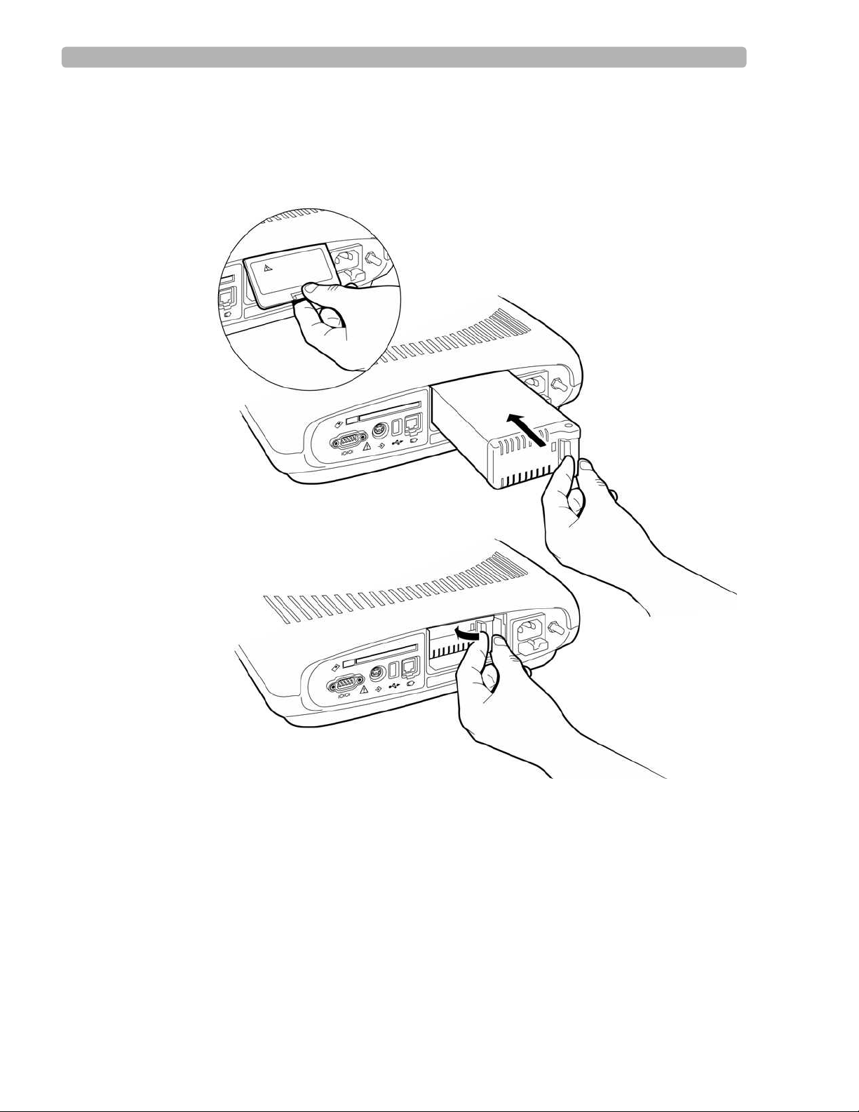
Replacing the Battery . . . . . . . . . . . . . . . . . . . . . . . . . . . . . . . . . . . . . . . . . . . . . . . . . . . . . . . .7-7
Replacing the AC Fuse . . . . . . . . . . . . . . . . . . . . . . . . . . . . . . . . . . . . . . . . . . . . . . . . . . . . . . .7-8
Replacing the Lead Wires on the PIM . . . . . . . . . . . . . . . . . . . . . . . . . . . . . . . . . . . . . . . . . . .7-9
Maintenance Tests. . . . . . . . . . . . . . . . . . . . . . . . . . . . . . . . . . . . . . . . . . . . . . . . . . . . . . . . . .7-10
PIM Test . . . . . . . . . . . . . . . . . . . . . . . . . . . . . . . . . . . . . . . . . . . . . . . . . . . . . . . . . . . . . .7-12
Barcode Reader Test . . . . . . . . . . . . . . . . . . . . . . . . . . . . . . . . . . . . . . . . . . . . . . . . . . . .7-12
Magnetic Card Reader Test . . . . . . . . . . . . . . . . . . . . . . . . . . . . . . . . . . . . . . . . . . . . . . .7-13
Printer Test. . . . . . . . . . . . . . . . . . . . . . . . . . . . . . . . . . . . . . . . . . . . . . . . . . . . . . . . . . . .7-13
Network Test . . . . . . . . . . . . . . . . . . . . . . . . . . . . . . . . . . . . . . . . . . . . . . . . . . . . . . . . . .7-16
Important Patient and Safety Information . . . . . . . . . . . . . . . . . . . . . . . . . . . . . . . . . . . . . . .7-16
Supplies and Ordering Information. . . . . . . . . . . . . . . . . . . . . . . . . . . . . . . . . . . . . . . . . . . . .7-20
Ordering Supplies . . . . . . . . . . . . . . . . . . . . . . . . . . . . . . . . . . . . . . . . . . . . . . . . . . . . . . .7-20
PageWriter Trim Cardiograph Supply Part Numbers. . . . . . . . . . . . . . . . . . . . . . . . . . .7-20
Patient Interface Module (PIM) . . . . . . . . . . . . . . . . . . . . . . . . . . . . . . . . . . . . . . . . .7-20
Replacement Fuse . . . . . . . . . . . . . . . . . . . . . . . . . . . . . . . . . . . . . . . . . . . . . . . . . . .7-20
Complete Lead Sets . . . . . . . . . . . . . . . . . . . . . . . . . . . . . . . . . . . . . . . . . . . . . . . . . .7-20
Replacement Lead Sets and Accessories . . . . . . . . . . . . . . . . . . . . . . . . . . . . . . . . .7-20
Electrodes. . . . . . . . . . . . . . . . . . . . . . . . . . . . . . . . . . . . . . . . . . . . . . . . . . . . . . . . . .7-21
Printer Paper . . . . . . . . . . . . . . . . . . . . . . . . . . . . . . . . . . . . . . . . . . . . . . . . . . . . . . .7-21
Optional Cardiograph Accessories . . . . . . . . . . . . . . . . . . . . . . . . . . . . . . . . . . . . . . . . .7-22
Optional Cardiograph Accessories . . . . . . . . . . . . . . . . . . . . . . . . . . . . . . . . . . . . . .7-22
Battery . . . . . . . . . . . . . . . . . . . . . . . . . . . . . . . . . . . . . . . . . . . . . . . . . . . . . . . . . . . .7-22
Contacting a Philips Response Center . . . . . . . . . . . . . . . . . . . . . . . . . . . . . . . . . . . . . . . . . .7-23
North America Response Centers . . . . . . . . . . . . . . . . . . . . . . . . . . . . . . . . . . . . . .7-23
South America Response Centers . . . . . . . . . . . . . . . . . . . . . . . . . . . . . . . . . . . . . .7-23
Europe Response Centers . . . . . . . . . . . . . . . . . . . . . . . . . . . . . . . . . . . . . . . . . . . . .7-23
Asia Response Centers . . . . . . . . . . . . . . . . . . . . . . . . . . . . . . . . . . . . . . . . . . . . . . .7-24
Specifications
Technical Specifications. . . . . . . . . . . . . . . . . . . . . . . . . . . . . . . . . . . . . . . . . . . . . . . . . . . . . . A-1
ECG Acquisition . . . . . . . . . . . . . . . . . . . . . . . . . . . . . . . . . . . . . . . . . . . . . . . . . . . . . . . . A-1
Keyboard . . . . . . . . . . . . . . . . . . . . . . . . . . . . . . . . . . . . . . . . . . . . . . . . . . . . . . . . . . . . . A-1
Screen Display . . . . . . . . . . . . . . . . . . . . . . . . . . . . . . . . . . . . . . . . . . . . . . . . . . . . . . . . . A-1
Patient Interface Module . . . . . . . . . . . . . . . . . . . . . . . . . . . . . . . . . . . . . . . . . . . . . . . . . A-1
Cardiograph Cart . . . . . . . . . . . . . . . . . . . . . . . . . . . . . . . . . . . . . . . . . . . . . . . . . . . . . . . A-1
Signal Processing/Acquisition . . . . . . . . . . . . . . . . . . . . . . . . . . . . . . . . . . . . . . . . . . . . . . A-2
Sampling Rate . . . . . . . . . . . . . . . . . . . . . . . . . . . . . . . . . . . . . . . . . . . . . . . . . . . . . . . A-2
Auto Frequency Response . . . . . . . . . . . . . . . . . . . . . . . . . . . . . . . . . . . . . . . . . . . . . . . . A-2
Rhythm Frequency Response . . . . . . . . . . . . . . . . . . . . . . . . . . . . . . . . . . . . . . . . . . . . . . A-2
Filters . . . . . . . . . . . . . . . . . . . . . . . . . . . . . . . . . . . . . . . . . . . . . . . . . . . . . . . . . . . . . . . . A-2
Printer . . . . . . . . . . . . . . . . . . . . . . . . . . . . . . . . . . . . . . . . . . . . . . . . . . . . . . . . . . . . . . . . A-2
Printer Resolution . . . . . . . . . . . . . . . . . . . . . . . . . . . . . . . . . . . . . . . . . . . . . . . . . . . A-2
Report Formats . . . . . . . . . . . . . . . . . . . . . . . . . . . . . . . . . . . . . . . . . . . . . . . . . . . . . . . . A-2
Contents-6 PageWriter Trim Cardiograph Instructions for Use
Page 9

Battery Operation . . . . . . . . . . . . . . . . . . . . . . . . . . . . . . . . . . . . . . . . . . . . . . . . . . . . . . A-3
Capacity . . . . . . . . . . . . . . . . . . . . . . . . . . . . . . . . . . . . . . . . . . . . . . . . . . . . . . . . . . . A-3
Recharge. . . . . . . . . . . . . . . . . . . . . . . . . . . . . . . . . . . . . . . . . . . . . . . . . . . . . . . . . . . A-3
Network Connection . . . . . . . . . . . . . . . . . . . . . . . . . . . . . . . . . . . . . . . . . . . . . . . . . . . . A-3
FAX Capability (optional). . . . . . . . . . . . . . . . . . . . . . . . . . . . . . . . . . . . . . . . . . . . . . . . . A-3
Modem (optional for USA and Canada) . . . . . . . . . . . . . . . . . . . . . . . . . . . . . . . . . . . . . A-3
Barcode Reader (optional) . . . . . . . . . . . . . . . . . . . . . . . . . . . . . . . . . . . . . . . . . . . . . . . . A-3
Magnetic Card Reader (optional) . . . . . . . . . . . . . . . . . . . . . . . . . . . . . . . . . . . . . . . . . . . A-3
ECG Storage . . . . . . . . . . . . . . . . . . . . . . . . . . . . . . . . . . . . . . . . . . . . . . . . . . . . . . . . . . . A-3
ECG File Formats . . . . . . . . . . . . . . . . . . . . . . . . . . . . . . . . . . . . . . . . . . . . . . . . . . . . . . . A-3
Power and Environment . . . . . . . . . . . . . . . . . . . . . . . . . . . . . . . . . . . . . . . . . . . . . . . . . . A-4
Line Power . . . . . . . . . . . . . . . . . . . . . . . . . . . . . . . . . . . . . . . . . . . . . . . . . . . . . . . . . A-4
Environmental Operating Conditions . . . . . . . . . . . . . . . . . . . . . . . . . . . . . . . . . . . . . . . A-4
Environmental Storage Conditions . . . . . . . . . . . . . . . . . . . . . . . . . . . . . . . . . . . . . . . . . A-4
Cardiograph Dimensions . . . . . . . . . . . . . . . . . . . . . . . . . . . . . . . . . . . . . . . . . . . . . . . . . A-4
Cardiograph Weight. . . . . . . . . . . . . . . . . . . . . . . . . . . . . . . . . . . . . . . . . . . . . . . . . . . . . A-4
Cardiograph Shipping Container Dimensions . . . . . . . . . . . . . . . . . . . . . . . . . . . . . . . . . A-4
Cardiograph Shipping Container Weight. . . . . . . . . . . . . . . . . . . . . . . . . . . . . . . . . . . . . A-4
Cardiograph Cart Dimensions . . . . . . . . . . . . . . . . . . . . . . . . . . . . . . . . . . . . . . . . . . . . . A-4
Cardiograph Cart Weight . . . . . . . . . . . . . . . . . . . . . . . . . . . . . . . . . . . . . . . . . . . . . . . . A-4
Cardiograph Cart Shipping Container Dimensions . . . . . . . . . . . . . . . . . . . . . . . . . . . . . A-5
Cardiograph Cart Container Weight. . . . . . . . . . . . . . . . . . . . . . . . . . . . . . . . . . . . . . . . A-5
Safety and Performance. . . . . . . . . . . . . . . . . . . . . . . . . . . . . . . . . . . . . . . . . . . . . . . . . . . . . . A-5
Electromagnetic Compatibility (EMC) . . . . . . . . . . . . . . . . . . . . . . . . . . . . . . . . . . . . . . . . . . A-5
Reducing Electromagnetic Interference . . . . . . . . . . . . . . . . . . . . . . . . . . . . . . . . . . . . . . A-5
Assembling the Patient Cable Arm
Overview . . . . . . . . . . . . . . . . . . . . . . . . . . . . . . . . . . . . . . . . . . . . . . . . . . . . . . . . . . . . . . . . . B-1
Assembly Instructions . . . . . . . . . . . . . . . . . . . . . . . . . . . . . . . . . . . . . . . . . . . . . . . . . . . . . . . B-2
PageWriter Trim Cardiograph Instructions for Use Contents-7
Page 10
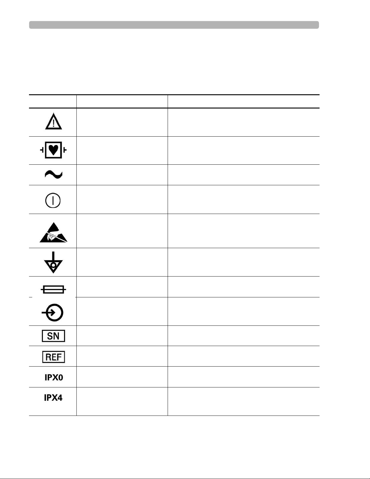
Safety Symbols Marked on the Cardiograph
1Safety Summary
Safety Symbols Marked on the Cardiograph
Symbol Name Description
Attention See PageWriter Trim Instructions for Use for
Type CF ECG physio isolation is type CF, defibrillator proof.
Alternating current Indicates that the cardiograph is receiving alternating
On/Standby Pressing the button with this symbol on it turns on the
information.
Electrical leakage current is suitable for all patient
applications including direct cardiac application.
currents.
cardiograph or puts the cardiograph into Standby
(power saving mode).
Do not touch exposed pins. Touching exposed pins can
Electrostatic Discharge
cause electrostatic discharge that can damage the
cardiograph.
Equipotential grounding post Equipotential grounding post used for establishing
common ground between instruments.
Fuse Cardiograph contains a 1.5 amp (250V) time-delay
fuse.
Input The connector near this symbol receives an incoming
signal.
Serial Number The number next to this symbol is the serial number of
the cardiograph.
Product model number The number next to this symbol is the product model
number of the cardiograph
Entry of liquids The cardiograph is not protected against splashing
water.
Entry of liquids The PIM (Patient Interface Module) is protected
against splashing water. Water splashed against the
PIM from any direction shall have no harmful effect.
PageWriter Trim Cardiograph Instructions for Use i
Page 11
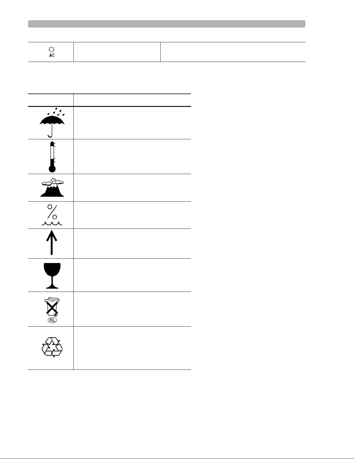
Safety Symbols Marked on the Cardiograph Packaging
AC power indicator light When lit, indicates that AC power is on. The battery is
charging when inserted into the cardiograph.
Safety Symbols Marked on the Cardiograph Packaging
Symbol Description
Keep dry.
o
Ambient temperature range of 0
o
to 50
C (122o F) (non-condensing) for
transport and storage.
Atmospheric pressure range of 466 hPa to
1014 hPa for transport and storage.
C (32o.F)
Relative humidity range of 25% to 80%
(non-condensing) for transport and storage.
Move and store packaging this end up.
Fragile.
Sealed lead acid battery. Do not dispose of
in trash. Follow local regulations for
disposing of as small chemical waste.
Recycle the packaging materials after use.
ii PageWriter Trim Cardiograph Instructions for Use
Page 12

Conventions Used in the Instructions for Use
Conventions Used in the Instructions for Use
WARNING Warning statements describe conditions or actions that may result in personal injury or
loss of life.
CAUTION Caution statements describe conditions or actions that may result in damage to equipment or
software.
NOTE Notes contain additional important information about a topic.
TIP A Tip contains suggested information on using a particular feature.
Menu item
Button name
Menu items and button names appear in a bold no-serif font.
Example: Highlight the
Config button.
Important Patient and Safety Information
The PageWriter Trim cardiograph isolates all connections to the patient from electrical ground
and all other conductive circuits in the cardiograph. This reduces the possibility of hazardous
currents passing from the cardiograph through the patient’s heart to ground, and from other
equipment connected to the patient passing through the leads into the cardiograph to ground.
WARNING Failure to follow these warnings could affect both patient and operator safety.
When operating the cardiograph on AC power, ensure that the cardiograph and all other
electrical equipment connected to or near the patient are effectively grounded.
Use only grounded power cords (three-wire power cords with grounded plugs) and
grounded electrical outlets. Never adapt a grounded plug to fit an ungrounded outlet by
removing the ground prong. Use the equipotential post when redundant earth ground is
necessary according to IEC 60601-1-1.
If a safe ground connection is not ensured, operate the cardiograph on battery power only.
The use of equipment that applies high frequency voltages to the patient (including
electrosurgical equipment and some respiration transducers) is not supported and may
produce undesired results. Disconnect the patient data cable from the cardiograph, or
detach the leads from the patient prior to performing any procedure that uses high
frequency surgical equipment.
Do not perform ST analysis on the R/T ECG screen display or on Rhythm reports when
the 0.5 Hz Baseline Wander filter is applied.
PageWriter Trim Cardiograph Instructions for Use iii
Page 13

Important Patient and Safety Information
If abnormal ECG data appears on the printed report, and the abnormal data does not have
a physiological origin, perform the printer diagnostic test to assess printer performance
(see page 7-13).
When printing a Rhythm report, there may be a slight delay before the Rhythm report
begins to print on the cardiograph. Rhythm printing is not completed in real-time.
Pace pulse tick marks will not print on an Auto report that uses simultaneous acquisition.
WARNING Do not touch accessible connector pins and the patient simultaneously.
Electrical shock hazard. Keep cardiograph, Patient Interface Module (PIM) and all
cardiograph accessories away from liquids. Do not immerse cardiograph, PIM, or other
accessories in any liquids.
Periodically inspect the patient data cable, lead wires, and AC power cord for any worn or
cracked insulation to ensure that no inner conductive material is exposed. Discard worn
accessories and replace them only with Philips Medical Systems accessories (see page 7-
20).
Keep the patient data cable away from power cords and any other electrical equipment.
Failure to do so can result in AC power line frequency interference on the ECG trace.
The Philips Medical Systems patient data cable (supplied with cardiograph) is an integral
part of the cardiograph safety features. Use of any other patient data cable may
compromise defibrillation protection, degrade cardiograph performance, and may result in
distorted ECG data.
Only qualified personnel may service the cardiograph or may open the cardiograph
housing to access internal cardiograph components. Do not open any covers on the
cardiograph. There are no internal cardiograph components that are serviced by the
operator.
Do not use this cardiograph near flammable anesthetics. It is not intended for use in
explosive environments or in operating rooms.
Do not touch the patient, the patient data cable, any unused patient leads, or the
cardiograph during defibrillation. Death or injury may occur from the electrical shock
delivered by the defibrillator.
The PageWriter Trim I is not recommended for diagnostic cardiograph use during
defibrillation. It does not provide less than 10 seconds of real-time data.
Always use electrode gel with reusable electrodes during defibrillation as ECG recovery
will be greater than 10 seconds. Philips Medical Systems recommends the use of
disposable electrodes at all times.
Ensure that the electrodes or lead wires do not come in contact with any other conductive
materials (including earth-grounded materials) especially when connecting or
disconnecting electrodes to or from a patient.
iv PageWriter Trim Cardiograph Instructions for Use
Page 14

Important Patient and Safety Information
Connecting multiple medical electrical equipment to the same patient may pose a safety
hazard due to the summation of leakage currents. Any combination of instruments should
be evaluated by local safety personnel before being put into service.
Portable medical equipment such as X-rays and MRI may produce electromagnetic
interference that produces noise in the ECG signal. Move the cardiograph away from these
potential sources of electromagnetic interference.
Do not pull on the paper while an ECG report is being printed. This can cause distortion of
the waveform and can lead to potential misdiagnosis.
Only use the Philips Medical Systems AC power cord supplied with the cardiograph.
Periodically inspect the AC power cord and AC power connector (rear of cardiograph, see
figure 1-2 on page 1-8) to ensure that both are in a safe and operable condition. If the AC
power cord or AC power connector is not in a safe or operable condition, operate the
cardiograph on battery power and contact Philips Medical Systems for service.
The cardiograph has been safety tested with the recommended accessories, peripherals,
and leads, and no hazard was found when the cardiograph is operated with cardiac
pacemakers or other stimulators.
Do not connect any equipment or accessories to the cardiograph that are not manufactured
or approved by Philips Medical Systems or that are not IEC 60601-1 approved. The
operation or use of non-approved equipment or accessories with the cardiograph is not
tested or supported, and cardiograph operation and safety are not guaranteed.
The list of cables and other accessories with which Philips claims compliance with the
emissions and immunity requirements of IEC standard 60601-1-2 are listed in “Supplies
and Ordering Information” on page 7-20.
WARNING When using additional peripheral equipment powered from an electrical source other
than the cardiograph, the combination is considered to be a medical system. It is the
responsibility of the operator to comply with IEC 60601-1-1 and test the medical system
according to the requirements. For additional information contact Philips Medical
Systems.
WARNING Do not use non-medical peripherals within 1.83 meters or 6 feet of a patient unless the
non-medical peripherals receive power from the cardiograph or from an isolation
transformer that meets medical safety standards.
Only install Philips Medical Systems software on the cardiograph. The installation or use
of software not approved by Philips Medical Systems is strictly prohibited and
cardiograph safety and performance are not guaranteed.
Only use Philips Medical Systems replacement parts and supplies with the cardiograph.
The use of non-approved replacement parts and supplies with the cardiograph is strictly
prohibited. Cardiograph safety and performance are not guaranteed when non-approved
replacement parts and supplies are used with the cardiograph.
PageWriter Trim Cardiograph Instructions for Use v
Page 15

The PageWriter Trim Cardiograph Intended Use
Manual measurements of ECG intervals and magnitudes should be performed on printed
ECG reports only. Do not make manual measurements of ECG intervals and magnitudes
on the R/T ECG display since these ECG representations are scaled.
Only use patient electrodes that are approved by Philips Medical Systems. The use of non-
approved patient electrodes may degrade cardiograph performance.
The Philips Medical Systems warranty is applicable only if you use Philips Medical
Systems approved accessories and replacement parts. See “Supplies and Ordering
Information” on page 7-20 for more information.
Before using the Patient Cable Arm with the cardiograph cart, properly install the counter
balance on the cardiograph base.
Only use the shielded LAN cable provided with the PageWriter Trim cardiograph, Philips
Part Number 989803138021. Do not use any other LAN cables with the PageWriter Trim
cardiograph. Use of unapproved LAN cables may result in radiated emissions that exceed
the limit specified by CISPR11 Class B.
The combined maximum weight that can be placed on the cardiograph cart shelf and the
top surface of the cart cannot exceed 20 kg (44 lbs). Do not place more than the specified
weight on the cardiograph top surface and shelf.
Do not connect any device to the RS-232 port on the rear of the cardiograph when the
patient data cable is connected to a patient.
There are no cardiograph parts that can be sterilized.
The cardiograph is not intended for direct, or invasive cardiac monitoring purposes.
Excessive, repetitive use of the cardiograph keyboard and the cardiograph Trim Knob may
result in a risk of developing carpal tunnel syndrome.
Ensure that the patient data cable is tucked away from the cardiograph cart wheels when
transporting the cardiograph. Ensure that the patient data cable does not present a hazard
when pushing the cardiograph cart.
The PageWriter Trim Cardiograph
Intended Use
The intended use of the cardiograph is to acquire multi-channel ECG signals from adult and
pediatric patients from body surface ECG electrodes and to record, display, analyze, and store
these ECG signals for review by the user. The cardiograph is to be used in healthcare facilities
by trained healthcare professionals. Analysis of the ECG signals is accomplished with
algorithms that provide measurements, data presentations, graphical presentations, and
interpretations for review by the user.
The interpreted ECG with measurements and interpretive statements is offered to the clinician
on an advisory basis only. It is to be used in conjunction with the clinician's knowledge of the
patient, the results of the physical examination, the ECG tracings, and other clinical findings.
vi PageWriter Trim Cardiograph Instructions for Use
Page 16

Indications for Use The Philips 12-Lead Algorithm
A qualified physician is asked to overread and validate (or change) the computer-generated
ECG interpretation.
Indications for Use
The cardiograph is to be used where the clinician decides to evaluate the electrocardiogram of
adult and pediatric patients as part of decisions regarding possible diagnosis, potential
treatment, effectiveness of treatment, or to rule out causes for symptoms.
The Philips 12-Lead Algorithm
The PageWriter Trim Cardiograph software uses the Philips 12-Lead Algorithm. The
algorithm in the software analyzes the morphology and rhythm on each of the 12 leads and
summarizes the results. The set of summarized measurements is then analyzed by the
clinically-proven ECG Analysis Program.
12-lead Reports may include or exclude ECG measurements, reasons, or analysis statements.
Intended Use
The intended use of the Philips 12-Lead Algorithm is to analyze multi-channel ECG signals
from adult and pediatric patients with algorithms that provide measurements, data
presentations, graphical presentations, and interpretations for review by the user.
The interpreted ECG with measurements and interpretive statements is offered to the clinician
on an advisory basis only. It is to be used in conjunction with the clinician's knowledge of the
patient, the results of the physical examination, the ECG tracings, and other clinical findings.
A qualified physician is asked to overread and validate (or change) the computer-generated
ECG interpretation.
Indications for Use
The Philips 12-Lead Algorithm is to be used where the clinician decides to evaluate the
electrocardiogram of adult and pediatric patients as part of decisions regarding possible
diagnosis, potential treatment, effectiveness of treatment, or to rule out causes for symptoms.
PageWriter Trim Cardiograph Instructions for Use vii
Page 17

1
1Getting Started
Welcome to the PageWriter Trim Cardiograph! With its intuitive operation, clearly labeled
PIM and lead wires, and convenient cart, it is the ideal cardiograph for processing large
volumes of ECGs quickly and easily.
The PageWriter Trim supports multiple ECG acquisition modes, display settings, and report
formats. Signal quality indicators provide instant feedback to the user to help ensure a quality
ECG each and every time.
This PageWriter Trim Cardiograph Instructions for Use provides comprehensive information
on the cardiograph and all of its components. It is intended to be used with the other materials
included in the PageWriter Trim Cardiograph Learning Kit.
NOTE Read and complete the materials included in the PageWriter Trim Cardiograph Learning Kit before
using the cardiograph. Read all Patient Safety information and pay close attention to all warnings and
cautions. For more information, see “Important Patient and Safety Information” on page -iii.
1-1
Page 18
Getting Started PageWriter Trim Cardiograph Learning Kit
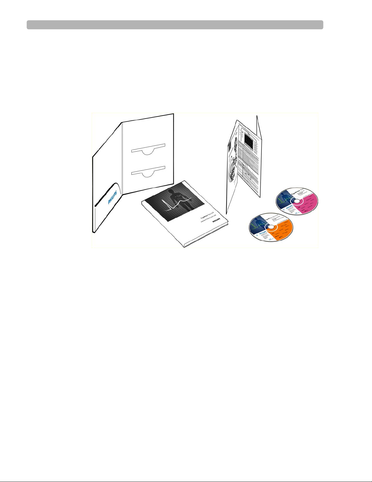
PageWriter Trim Cardiograph Learning Kit
Philips Medical Systems provides detailed instructional and reference materials in the
PageWriter Trim Learning Kit
The PageWriter Trim Learning Kit contains the Getting Started Guide, a Quick Help Card,
and the User Documentation and Interactive Training CDs.
Figure 1-1 The PageWriter Trim Cardiograph Learning Kit
A
B
C
About the PageWriter Trim Learning Kit
Getting Started Guide (A)
This guide includes important information that must be read before operating the
cardiograph. It includes an overview of cardiograph features and functions, assembly and
setup instructions, how to configure the cardiograph, and how to order supplies.
Quick Help Card (B) This card provides quick reference information about basic
cardiograph features, lead placement, and signal quality indicators. It is also provided as a
PDF file on the PageWriter Trim User Documentation CD.
D
PageWriter Trim Cardiograph Interactive Training Program CD (C)
The interactive training CD contains a computer-based training program about the proper
recording of ECGs and how to operate the cardiograph.
Use this program to train the entire ECG staff in the proper operation of the cardiograph.
To run the interactive training program:
X Insert the CD into a PC CD-ROM drive. The CD only works on PCs with a Windows
operating system.
The interactive training program starts automatically.
1-2 PageWriter Trim Cardiograph Instructions for Use
Page 19

Getting Started Attaching the Cardiograph to the Cart
PageWriter Trim User Documentation CD (D)
The User Documentation CD contains the following files:
– Philips 12-Lead Algorithm Physician’s Guide
This PDF file describes the Philips 12-Lead Algorithm, and lists all of the interpretive
statements included in the 0A criteria.
– PageWriter Trim Instructions for Use
This PDF file includes complete information on all aspects of using and maintaining
the cardiograph.
– PageWriter Trim Quick Help Card
A PDF version of the Quick Help Card provided in the Learning Kit.
– PageWriter Trim Cardiograph XML Schema (English only)
The schema for the XML ECG data exported from the PageWriter Trim cardiograph.
To view user documentation:
X Insert the CD into a PC CD-ROM drive. The CD only works on PCs with a Windows
operating system.
The user documentation CD main menu opens automatically. Click on a blue button or the
file name to open the file.
NOTE Adobe Acrobat Reader does not need to be installed on the PC to view the PDF files on the CD. If
PDF files from the CD are saved to a PC hard drive, Acrobat Reader will need to be installed on the
PC in order to view the files. For a free install go to: www.adobe.com.
1
If the menu does not automatically appear, open the CD in Windows Explorer.
2 Double-click the file menu.pdf on the CD. The PDF menu appears. Any of the files on the
CD may be printed or saved to a PC hard drive.
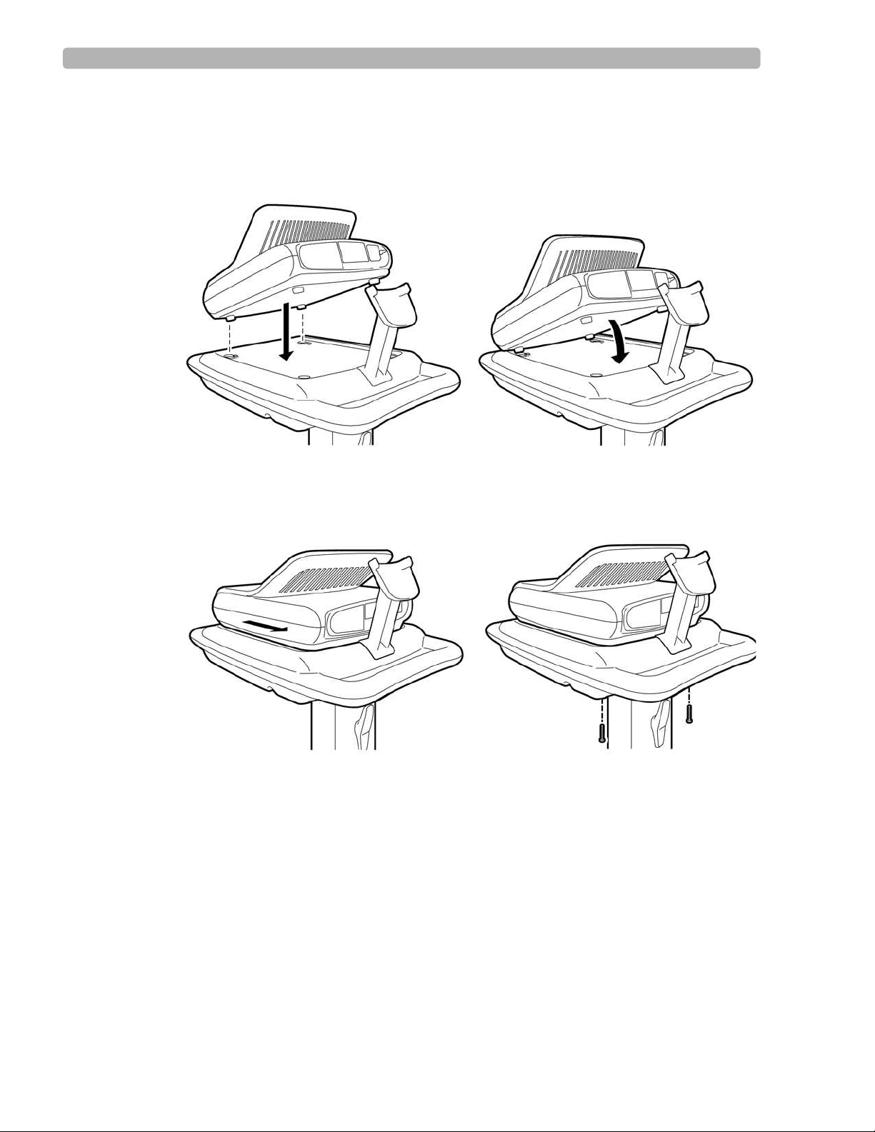
Attaching the Cardiograph to the Cart
The PageWriter Trim cardiograph is available with an optional cart that includes a storage
shelf and a holder for the PIM (Patient Interface Module).
CAUTION Follow the procedure below to ensure that the cardiograph is securely fastened to the cart before
use.
PageWriter Trim Cardiograph Instructions for Use 1-3
Page 20
Getting Started Attaching the Cardiograph to the Cart
To attach the cardiograph to the cart:
Align the front feet of the cardiograph with the front locking holes on the cart. Align the
1
rear feet of the cardiograph with the rear screw holes on the cart. Lower the cardiograph
onto the cart.
2 Slide the cardiograph back to lock the front and rear feet into place. Insert the screws
through the bottom of the cart and through the screw holes. Tighten the screws with a
Phillips head screwdriver.
1-4 PageWriter Trim Cardiograph Instructions for Use
Page 21
Getting Started PageWriter Trim I Cardiograph Parts
PageWriter Trim I Cardiograph Parts
The following sections show front, side, and rear views of the PageWriter Trim I cardiograph.
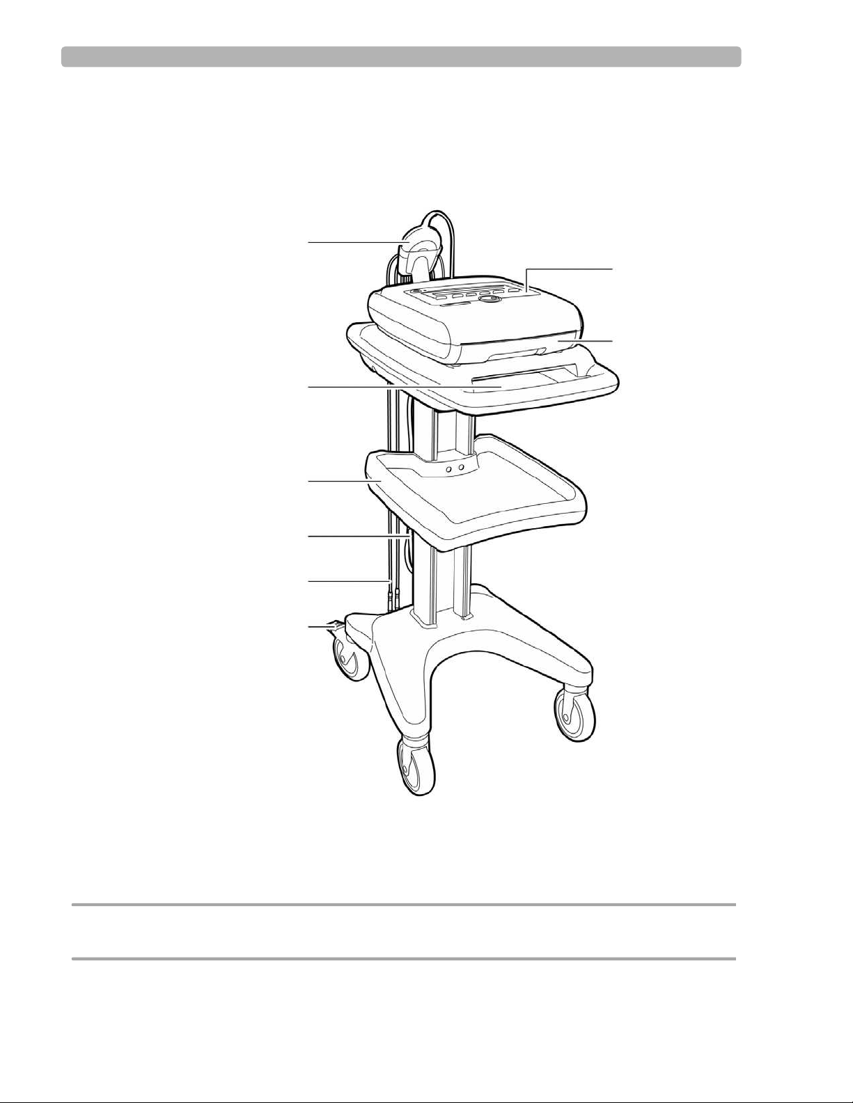
Figure 1-1 PageWriter Trim I Cardiograph and Cart (Front View)
A
G
H
B
C
D
E
F
A Patient Interface Module (PIM) E PIM Leads
B Printer paper/report storage slot F Wheel Brake
C Storage Shelf G Control Panel
D AC Power Cord H Printer Paper Drawer
CAUTION Always lock the wheel brake (F) when the cart is not in use. Press down on the wheel brake to set or
to release the wheel brake.
PageWriter Trim Cardiograph Instructions for Use 1-5
Page 22
Getting Started PageWriter Trim I Cardiograph Parts
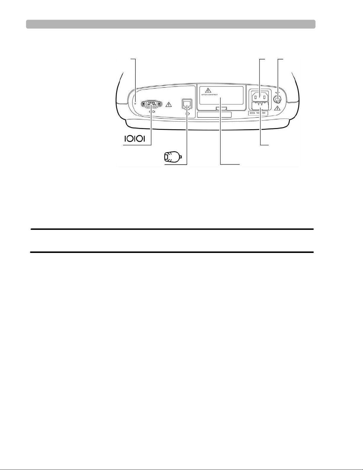
Figure 1-2 PageWriter Trim I Cardiograph (Rear View)
IK
NM
J
LO
I Reset Button M Battery Door
J AC Power Cord Connector N PIM Connector
K Equipotential Post O Serial Connector (not supported)
L Fuse Door
WARNING Do not connect a LAN cable connector to the PIM connector.
Do not plug a telephone connector into the PIM connector.
1-6 PageWriter Trim Cardiograph Instructions for Use
Page 23
Getting Started PageWriter Trim II and III Cardiograph Parts
PageWriter Trim II and III Cardiograph Parts
The following sections show front, side, and rear views of the PageWriter Trim II and III
cardiographs.
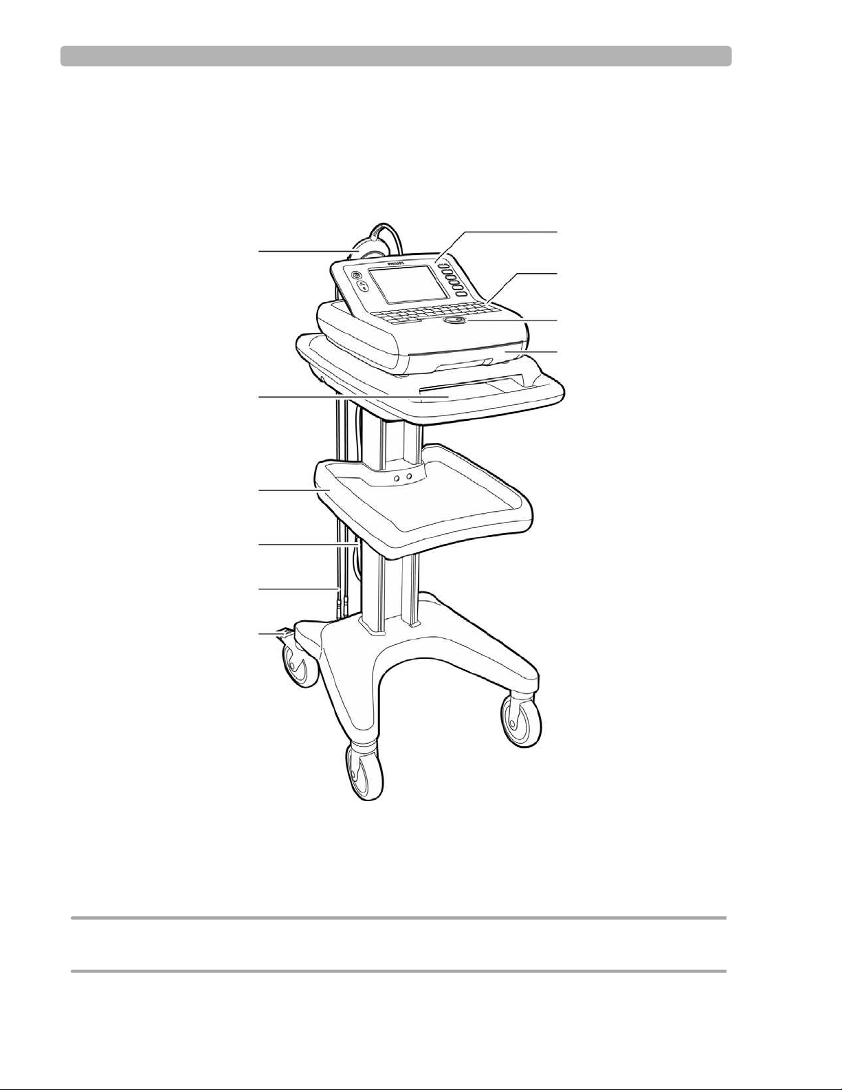
Figure 1-1 PageWriter Trim II and III Cardiograph and Cart
(Front View)
G
A
H
I
J
B
C
D
E
F
A Patient Interface Module (PIM) F Wheel Brake
B Printer paper/report storage slot G Control Panel
C Storage Shelf H Keyboard
D AC Power Cord I Trim Knob
E PIM Leads J Printer Paper Drawer
CAUTION Always lock the wheel brake (F) when the cart is not in use. Press down on the wheel brake to set or
to release the wheel brake.
PageWriter Trim Cardiograph Instructions for Use 1-7
Page 24
Getting Started PageWriter Trim II and III Cardiograph Parts
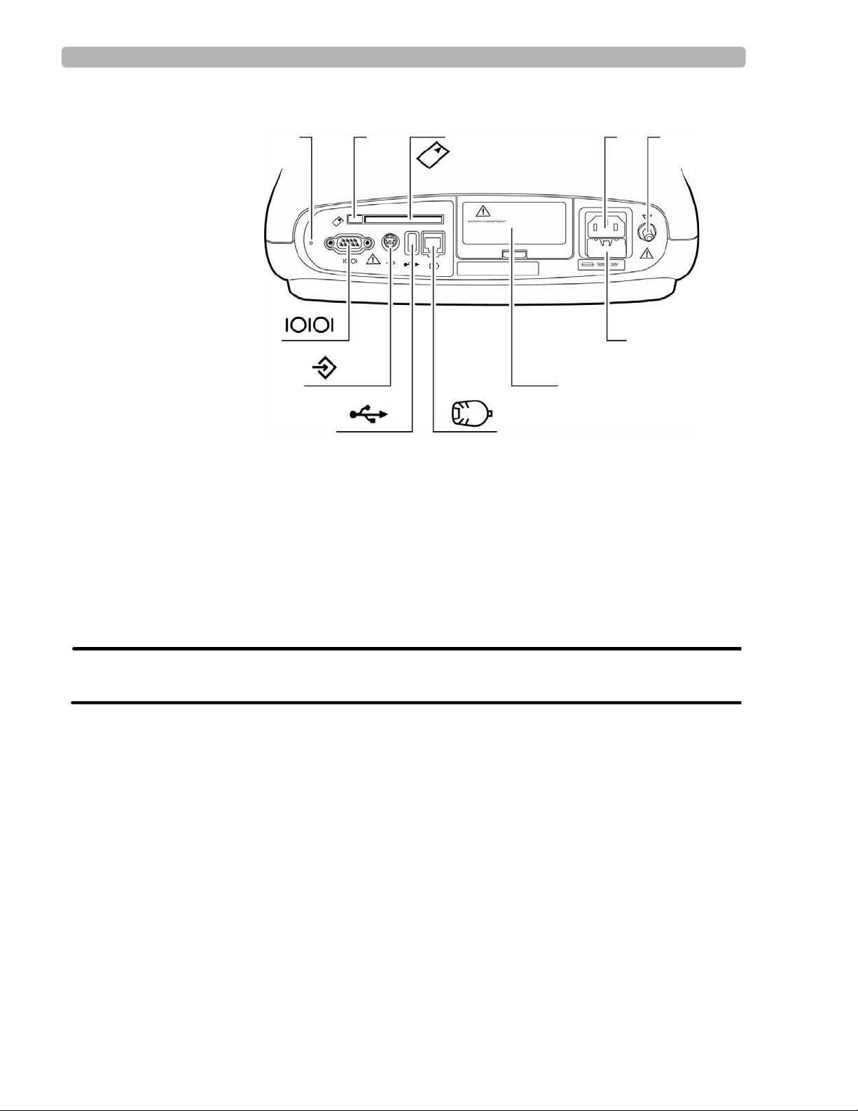
Figure 1-2 PageWriter Trim II and III Cardiograph (Rear View)
KL
U
T
M
Q
RS
NO
P
K Reset Button Q Battery Door
L PC Card Eject Button R PIM Connector
M PC Card Slot S SmartCard Reader (USB) Connector
N AC Power Connector T Barcode Reader or Magnetic Card
Reader Connector
O Equipotential Post U Serial Connector (not supported)
P Fuse Door
WARNING Do not connect the LAN cable connector into the PIM connector.
Do not plug a telephone connector into the PIM connector.
1-8 PageWriter Trim Cardiograph Instructions for Use
Page 25
Getting Started Installing the Battery
Installing the Battery
The cardiograph is shipped with one removable battery. Install the battery before plugging the
cardiograph into AC power.
Figure 1-3 Installing the Battery
To install the battery:
1
Open the battery door on the rear of the cardiograph. Push the recessed tab in and pull it
down to open the battery door.
2 Insert the battery into the compartment with the connector facing down and the pull tab
facing out.
3 Push in the pull tab to lock it.
4 Reattach and close the battery door.
5 Attach the AC power cord to the rear of the cardiograph.
PageWriter Trim Cardiograph Instructions for Use 1-9
Page 26

Getting Started Installing the Battery
6 Plug the AC power cord into a grounded electrical outlet. Check that the green AC power
indicator light is on (front of cardiograph).
7 Charge the battery for at least 24 hours before mobile use.
Battery Charging Indicator, PageWriter Trim II and III
On the PageWriter Trim II and III, a lightening bolt icon ( ) appears on the Battery
Level Indicator on the Status Bar when the cardiograph is plugged into AC power and the
battery is charging. Check the Battery Power Indicator on the Status Bar to ensure that the
battery is fully charged, see “PageWriter Trim II and III Status Bar” on page 1-27. The
cardiograph can operate on AC power while the battery is charging, but the battery will
charge at a slower rate.
Battery Charging Indicator, PageWriter Trim I
On the PageWriter Trim I, the following battery icon ( ) flashes on the LCD display
when the cardiograph is plugged into AC power and the battery is charging, see “LCD
Display” on page 1-24. The battery level indicator displays the following battery icon
( ) when the battery is fully charged. The cardiograph can operate on AC power while
the battery is charging, but the battery will charge at a slower rate.
1-10 PageWriter Trim Cardiograph Instructions for Use
Page 27
Getting Started Loading the Printer Paper
Loading the Printer Paper
Replace the printer paper when a red stripe appears on the printed ECG report. Only use
Philips Medical Systems replacement printer paper. For part number and ordering
information, see page 7-20.
Tips for loading printer paper
Always load less than 100 sheets of printer paper into the paper tray
Ensure that the entire first page of the new paper roll is fully draped over the roller before
closing the printer door
PageWriter Trim II and III:
Ensure that the paper size configured for the cardiograph is the same size paper being
loaded into the paper drawer (see page 5-18)
Figure 1-4 Loading Printer Paper
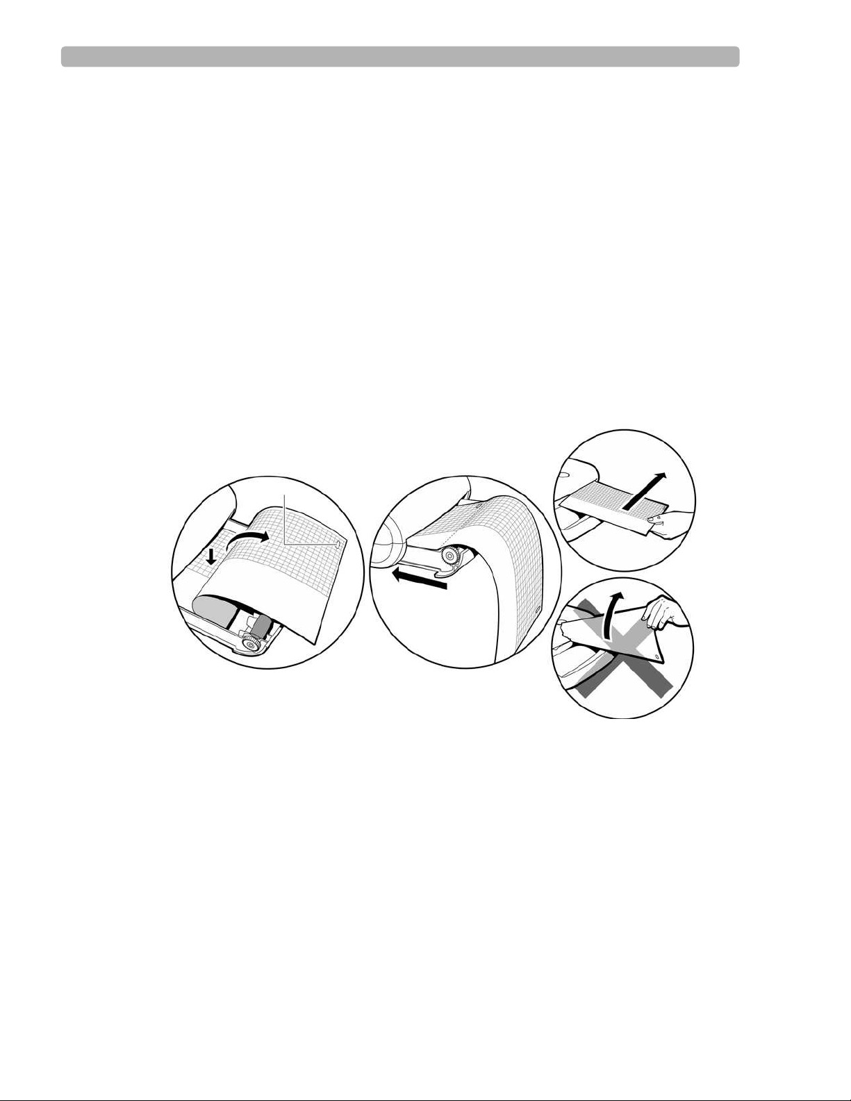
A
A Paper sensor hole
To change the printer paper:
Open the paper drawer on the front of the cardiograph.
1
2 Insert a new pack of printer paper with the printed side facing up. Ensure that no more
than 100 sheets are being inserted into the paper tray.
3 Ensure that the paper sensor hole (A) is positioned as shown in Figure 1-4.
4 Drape the entire first sheet over the roller. Ensure that the perforated edge of the paper
aligns with the edge of the paper drawer.
5 Close the paper drawer.
6 Tear off the first sheet as shown in Figure 1-4.
PageWriter Trim Cardiograph Instructions for Use 1-11
Page 28
Getting Started Patient Interface Module (PIM)
Patient Interface Module (PIM)
The Patient Interface Module (PIM) is a hand-held device that connects to the cardiograph.
The lead wires on the PIM attach to the electrodes placed on the patient. The exterior of the
PIM is labeled and color-coded for quick and easy lead identification.
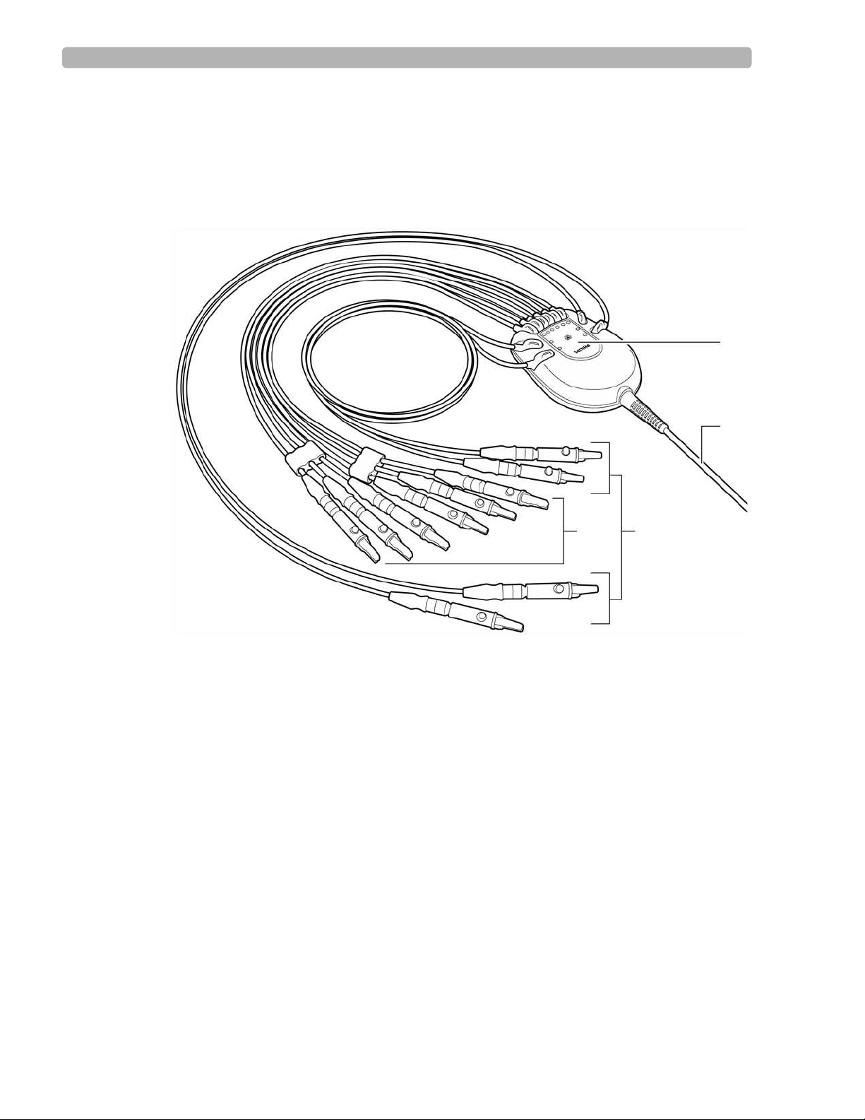
Figure 1-5 Patient Interface Module
A
B
CD
A Lead Wire Labeling C Limb Lead Wires
B Patient Data Cable D Precordial (Chest) Lead Wires
1-12 PageWriter Trim Cardiograph Instructions for Use
Page 29
Getting Started Patient Interface Module (PIM)
Inserting the Lead Wires into the PIM
The exterior of the PIM is color-coded for quick and easy lead identification. The lead wires
that are included with the cardiograph must be inserted into the correct lead wire connector on
the PIM.
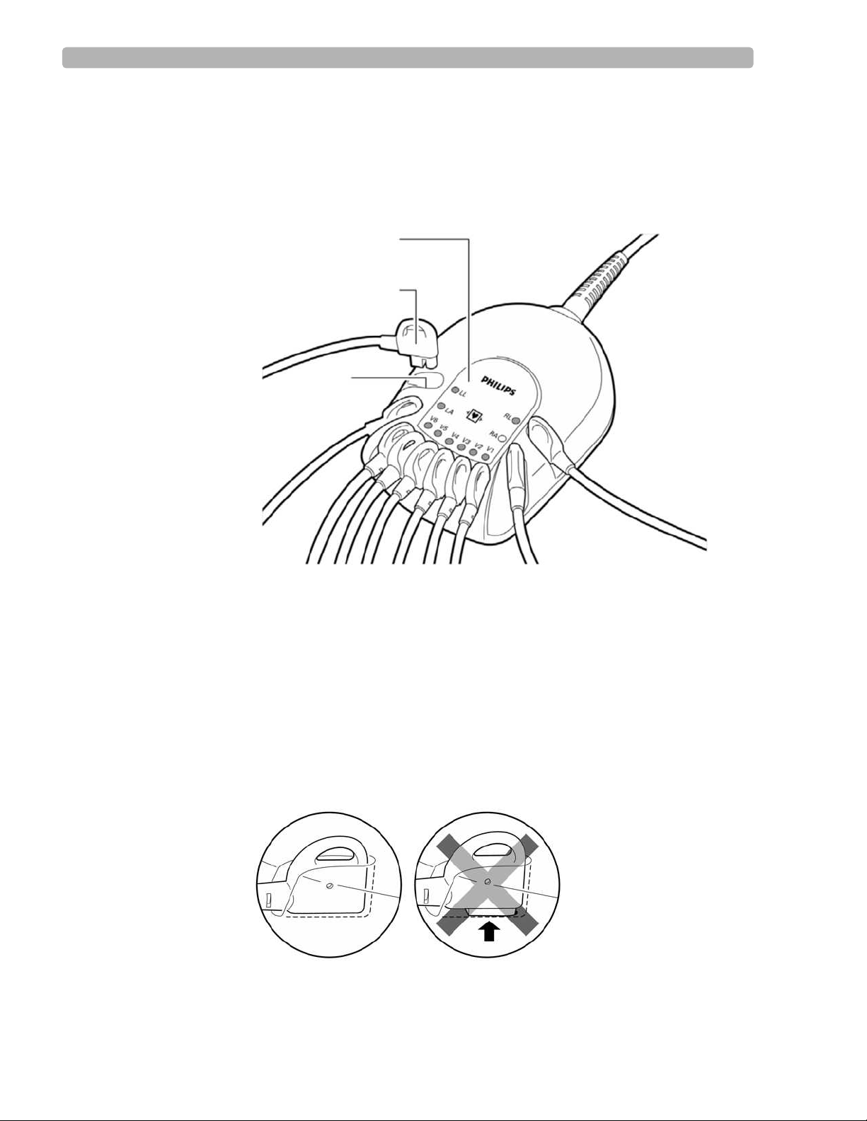
Figure 1-6 PIM connector and lead wire labeling
C
B
A
A Lead Wire Connector C Lead Wire Labeling
B Lead Wire
To insert the lead wires into the PIM:
Locate the lead wires in the cardiograph packaging.
1
2 Match the lead wire to the correct lead wire connector on the PIM.
3 Insert each lead wire into the correct lead wire connector on the PIM.
4 Push down on the lead wire to ensure that there is no gap between the lead wire and the
connector.
PageWriter Trim Cardiograph Instructions for Use 1-13
Page 30
Getting Started Patient Interface Module (PIM)
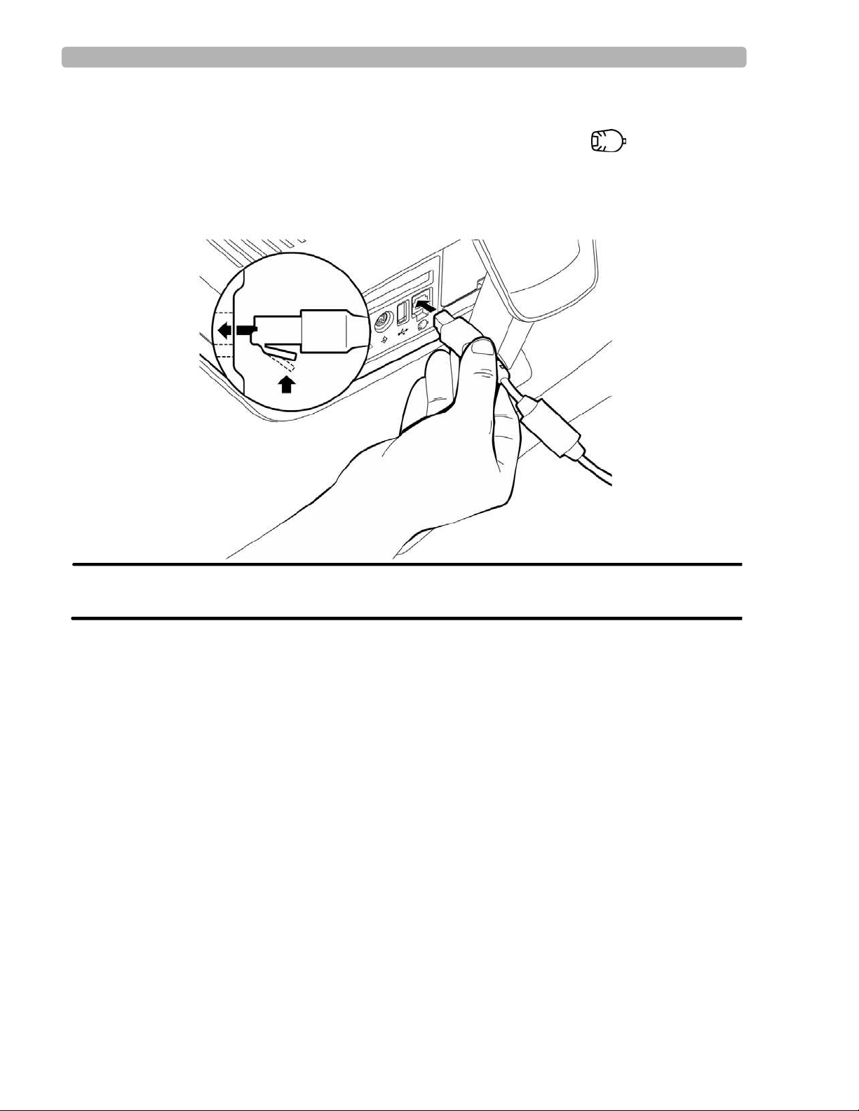
Connecting the PIM to the Cardiograph
Connect the patient data cable on the PIM to the PIM connector port ( ) on the rear panel
of the cardiograph.
To connect the PIM to the cardiograph:
X Connect the patient data cable to the PIM connector port on the rear of the cardiograph.
WARNING To ensure safety and prevent damage to the system, only connect the patient data cable
to the PIM connector port on the rear of the cardiograph.
1-14 PageWriter Trim Cardiograph Instructions for Use
Page 31

Getting Started Patient Interface Module (PIM)
Placing the PIM in the Holder
Place the PIM in the holder when not in use. The PIM holder is located on the rear of the
optional cardiograph cart. Ensure that the lead wires are facing down.
Figure 1-7 Inserting the PIM into the holder
CAUTION Ensure that the PIM patient data cable and lead wires do not drag on the ground or become tangled in
the cart wheels.
PageWriter Trim Cardiograph Instructions for Use 1-15
Page 32

Getting Started Using the PC Card Slot
Using the PC Card Slot
PageWriter Trim II and III only
The PC Card slot (rear of cardiograph) is used with the optional PC Card, LAN Card, or
Modem Card. All of these are optional accessories available with the cardiograph and are
inserted into the PC Card slot. For information on ordering any of these accessories, see
“Supplies and Ordering Information” on page 7-20.
Using the PC Card
The PC Card is an optional accessory available with the cardiograph. The PC Card contains a
128 MB removable memory card that can be used to transfer Auto reports to and from the
cardiograph. For information on transferring Auto reports, “Transferring Auto Reports to a
TraceMaster ECG Management System” on page 4-9.
Figure 1-8 The PC Card
AB
A PC Card Adapter B 128 MB Removable Memory Card
1-16 PageWriter Trim Cardiograph Instructions for Use
Page 33

Getting Started Using the PC Card Slot
Using the Modem Card
The modem card is an optional accessory used with the cardiograph to fax Auto reports, or to
transfer Auto reports by modem to a TraceMaster ECG Management System (version A.04.02
or higher) or to a TraceMasterVue ECG Management System (version A.01 or higher). For
information on ordering the modem card, “Supplies and Ordering Information” on page 7-20.
The modem card used either as a fax or as a modem must be configured before initial use with
the cardiograph, see page 5-24. For information on faxing reports or transferring reports by
modem, see page 4-9.
Figure 1-9 The Modem Card
Using the LAN Card
The LAN Card is used with the cardiograph to provide a network connection between the
cardiograph and a network. The LAN Card must be configured before using it with the
cardiograph, see page 5-27. For information on ordering the LAN card, see “Supplies and
Ordering Information” on page 7-20.
CAUTION Only use the shielded LAN cable provided with the PageWriter Trim cardiograph. Do not use LAN
cables with the cardiograph that have not been approved by Philips Medical Systems.
Figure 1-10 LAN Card
PageWriter Trim Cardiograph Instructions for Use 1-17
Page 34

Getting Started Using the Barcode Reader
Inserting or Removing a PC Card
The PC Card, modem card, and LAN card are all inserted into the PC Card slot.
Figure 1-11 Removing the PC Card from the cardiograph
A
A PC Card eject button
To insert or remove a card from the PC Card slot:
Insert the card into the PC Card slot (rear of cardiograph) and gently push it in.
1
2 Push the PC Card eject button to the left of the card slot to eject the card.
3 Pull out the card.
Using the Barcode Reader
PageWriter Trim II and III only
The barcode reader is an optional accessory available with the cardiograph. The barcode
reader is used to quickly enter Patient ID information by scanning a barcode.
The barcode reader attaches to the barcode reader connector ( ) on the rear panel of the
cardiograph. For information on ordering the barcode reader, see “Supplies and Ordering
Information” on page 7-20.
Figure 1-12 The Barcode Reader
1-18 PageWriter Trim Cardiograph Instructions for Use
Page 35

Getting Started Using the Magnetic Card Reader
Using the Magnetic Card Reader
PageWriter Trim II and III only
The magnetic card reader is an optional accessory available with the cardiograph. The
magnetic card reader is used to quickly enter Patient ID information. The Patient ID fields that
are entered when a magnetic card is scanned are configurable, see page 5-35.
The magnetic card reader attaches to the magnetic card reader connector ( ) on the rear
panel of the cardiograph. For information on ordering the magnetic card reader, see “Supplies
and Ordering Information” on page 7-20.
Figure 1-13 The Magnetic Card Reader
Using the SmartCard Reader
PageWriter Trim II and III only
The SmartCard Reader is an optional accessory available with the cardiograph. The
SmartCard Reader is used to quickly enter Patient ID information.
The SmartCard Reader attaches to the USB connector ( ) on the rear panel of the
cardiograph. For information on ordering the SmartCard Reader, see “Supplies and Ordering
Information” on page 7-20.
Figure 1-14 The SmartCard Reader
PageWriter Trim Cardiograph Instructions for Use 1-19
Page 36

Getting Started Powering On the Cardiograph
Powering On the Cardiograph
Ensure that the battery is inserted into the cardiograph before turning on AC power to the
cardiograph. See “Installing the Battery” on page 1-9. The cardiograph runs on battery or on
AC power. The battery must be inserted into the cardiograph at all times. The cardiograph
printer will not function without the battery installed.
With the battery fully charged, the cardiograph will print up to 30 Auto ECGs or provide 30
minutes of continuous Rhythm printing. The green AC indicator light shows that the battery is
charging when the cardiograph is plugged into AC power. Plug the cardiograph into AC power
whenever possible.
To disconnect the cardiograph from AC power, unplug the AC power cord from the grounded
electrical outlet.
Check the Battery Power Indicator on the Status Bar to ensure that the battery is fully charged
before operating the cardiograph on battery power only. On the PageWriter Trim I the
following icon ( ) displays on the LCD display to indicate that the battery is fully charged.
On the PageWriter Trim II and III the following icon ( ) displays on the Status Bar
to indicate that the battery is fully charged.
For information about PageWriter Trim II and III power management options, see “Using the
On/Standby Button” on page 1-21.
A
B
A
B
A On/Standby button B AC Power Indicator Light
To turn on the cardiograph:
Plug the AC power cord into the AC power connector on the rear of the cardiograph.
1
2 Plug the AC power cord into a grounded electrical outlet with appropriate electrical
ratings. The AC power indicator light on the front panel of the cardiograph is illuminated
when the cardiograph is plugged into AC power.
3 Press the On/Standby or On button on the front of the cardiograph.
1-20 PageWriter Trim Cardiograph Instructions for Use
Page 37

Getting Started Using the On/Standby Button
Using the On/Standby Button
PageWriter Trim II and III only
The On/Standby button is used to put the cardiograph into Standby and to shut off the
cardiograph.
Table 1-1 Standby and Shut Down Description
Mode Description
Standby
Shut Down
The cardiograph is in a “sleep” mode
The display screen is black
Patient ID information is not saved when the
cardiograph is put into Standby
Temporary report settings are saved when the
cardiograph is put into Standby
The battery charges when the cardiograph is
plugged into AC power
The green Standby indicator light (front of
cardiograph) is lit
The cardiograph returns to the previously viewed
screen when taken out of Standby
Use between brief periods of inactivity to save
battery power
The cardiograph is shut down
The display screen is black
The battery charges when the cardiograph is
plugged into AC power
The cardiograph starts up from the reboot screen
when turned on
Use for extended periods of cardiograph inactivity
TIP There are configurable features on the cardiograph that can be used to help prolong battery life (see
page 5-18). Proper battery care and maintenance will also help to prolong battery life (see page 7-5).
To put the cardiograph into Standby:
X Press the On/Standby button. A message appears that the cardiograph is entering Standby.
The green Standby indicator light (front of cardiograph) is lit. The battery is charging in
Standby when the cardiograph is plugged into AC power.
NOTE The cardiograph cannot be put into Standby if the Patient ID screen is open or if the cardiograph is
printing a report.
PageWriter Trim Cardiograph Instructions for Use 1-21
Page 38

Getting Started Using the Trim Knob
To exit Standby:
X Press the On/Standby button. The splash screen appears. The previously viewed screen
appears.
To shut down the cardiograph:
X Press and hold the On/Standby button for 3 seconds. Release the button. A message
appears that the cardiograph is shutting down.
To turn on the cardiograph:
X Press the On/Standby button. The cardiograph displays a series of startup screens and then
the R/T (real-time) ECG screen displays.
Using the Trim Knob
All models of the PageWriter Trim cardiograph have a Trim Knob that is used to scroll
through and select items on any display menu.
Figure 1-15 The Trim Knob
To use the Trim Knob:
Turn the Trim Knob left or right to scroll through the selections in a menu list.
1
2 Push the Trim Knob to select an item on the menu.
PageWriter Trim I Features
The PageWriter Trim I has an LCD display that shows all operating information. The buttons
on the main panel of the cardiograph are used for all cardiograph functions. Simply select the
buttons on the main panel to use the different functions on the cardiograph.
NOTE Complete the Interactive Training Program on CD before operating the cardiograph. The Interactive
Training program includes instructional information on what an ECG is, patient preparation
techniques, how to operate the cardiograph, and quality assessment techniques to ensure high-quality
ECGs. For information on using the training program, see page 1-2.
1-22 PageWriter Trim Cardiograph Instructions for Use
Page 39

Getting Started PageWriter Trim I Features
Control Panel
The control panel contains all of the main functions on the cardiograph. For more information
on any feature, see “The Patient Session" on page 2-1.
Figure 1-16 PageWriter Trim I Control Panel
A
B
C
D
E
A On/off button D Function Buttons
B AC power on indicator light E Trim Knob
C LCD Display
PageWriter Trim Cardiograph Instructions for Use 1-23
Page 40

Getting Started PageWriter Trim I Features
LCD Display
The LCD display shows the current settings on the cardiograph.
Figure 1-17 PageWriter Trim I LCD Display
AC
B
Table 1-2 PageWriter Trim I LCD Display
Label Description
A
B
C
D
Heart Beat Detector
For more information, see page 2-8.
Leads Off Indicator
For more information, see page 2-8.
Signal Quality Indicator
For more information, see page 2-8.
Battery Level Indicator
For more information, see page 1-9.
D
FGHI
E
E
F
G
H
I
Waveform Speed (mm/sec)
Waveform Size (mm/mV)
Filter Settings
For more information, see page 2-13.
Rhythm Lead
For more information, see page 2-27.
Report Format
For more information, see page 2-24.
1-24 PageWriter Trim Cardiograph Instructions for Use
Page 41

Getting Started PageWriter Trim I Features
Function Buttons
All of the functions on the PageWriter Trim I cardiograph are controlled by the function
buttons located on the main panel of the cardiograph.
Figure 1-18 Function Buttons on PageWriter Trim I cardiograph
AB DCEF
Table 1-3 Function Button description
Label Button Push button to...
A
B
C
D
ID Enter Patient ID information (age, gender).
For more information, see page 2-18.
Auto Take a 3x4, 1R Auto report.
For more information, see page 2-24.
Rhythm Print out a continuous Rhythm report (3 or 6 leads)
until the Stop button (
For more information, see page 2-27.
F) is pressed.
Copy Print out a copy of the last recorded Auto 12-lead
report.
E
Page Advance the printer paper to the beginning of the next
page.
F
Stop Stop the printing of a Rhythm report.
Return to the previous screen on the LCD display.
PageWriter Trim Cardiograph Instructions for Use 1-25
Page 42

Getting Started PageWriter Trim II and III Features
PageWriter Trim II and III Features
For more information on any feature, see “The Patient Session" on page 2-1.
Figure 1-19 PageWriter Trim II and III Control Panel
A
B
C
Table 1-4 PageWriter Trim II and III Control Panel
Label Feature Name Description
A On/Standby
button
Push to turn on the cardiograph or to put the
cardiograph into Standby (power save) when the
cardiograph is not in use.
Push and hold for 3 seconds, then release to shut down
the cardiograph for extended periods of inactivity.
B Standby
indicator
When lit, the cardiograph is in Standby (power save) mode
and the screen is black.
D
E
F
G
H
I
J
K
L
C AC Power
When lit, the cardiograph is plugged into AC power.
Indicator
D Status Bar
E Waveform
Displays current cardiograph settings including: Leads
For more information, see page 1-27.
Displays real-time waveforms (waveforms are color-
Display
For more information, see page 2-10.
F Command
Buttons contain the major functions of the
Toolbar
For more information, see page 1-28.
1-26 PageWriter Trim Cardiograph Instructions for Use
off, battery level indicator, filters, pacing detection
settings, and Patient name and ID.
coded by signal quality on the PageWriter Trim III).
cardiograph, with the current date and time at the
right.
Page 43

Getting Started PageWriter Trim II and III Features
Table 1-4 PageWriter Trim II and III Control Panel (continued)
Label Feature Name Description
G ID button
Press button to enter Patient ID information at the
beginning of a patient session.
For more information, see page 2-19.
H Auto button
I Rhythm button
Press button to print out an Auto 12-lead report.
For more information, see page 2-24.
Press button to print out a continuous Rhythm report
(up to 12 leads) until the Stop button (
For more information, see page 2-27.
J Copy button
Press button to print out a copy of the last recorded Auto
12-lead report.
K Page button
Press button to advance the printer paper to the beginning
of the next page.
L Stop button
Press button to stop the printing of a Rhythm report or any
other printing function.
PageWriter Trim II and III Status Bar
L) is touched.
The Status Bar includes all current operating information for the cardiograph.
Figure 1-20 Status Bar
ADCEB
RL
60~
0.15 - 150 Hz
P?
ID:
NAME
:
Table 1-5 Status Bar Description
Label Feature Name Description
A Leads Off
Indicator
B Battery Level
Indicator
C Filter Settings
Displays the name of any loose or
disconnected leads or electrodes.
For more information, see page 2-9.
Displays the current battery level and if the
batteries are charging ( ).
Displays the filter settings for the current
patient session.
For more information, see page 2-11.
PageWriter Trim Cardiograph Instructions for Use 1-27
Page 44

Getting Started PageWriter Trim II and III Features
Table 1-5 Status Bar Description (continued)
Label Feature Name Description
D Pacing Detection
Settings
E Patient Name
and ID
Displays the Pacing Detection Setting
used for the current patient session.
For more information, see page 2-30.
Displays the patient name and ID for the
current patient session.
PageWriter Trim II and III Command Toolbar
The Command Toolbar includes all of the main functions of the cardiograph. Turn the Trim
Knob to highlight a button. Press the Trim Knob to select the button.
Figure 1-21 Command Toolbar
REPORT FILTER DISCLOSE ORDER ARCHIVE HELPCONFIG
Table 1-6 Command Toolbar
Button Select this Button to...
Change Auto report settings.
Change pacing detection settings.
REPORT
Change the leads on a Rhythm report.
Change the lead on a Disclose report.
Turn on or turn off optional filters (Baseline Wander,
FILTER
DISCLOSE
ORDERS
ARCHIVE
1-28 PageWriter Trim Cardiograph Instructions for Use
For more information, see page 2-11.
Print a report of one minute of continuous waveform
For more information, see page 2-29.
Enter an Order, edit an Order, or to delete an Order
For more information, see page 4-1.
Review, edit, or print saved 12-lead reports
Transfer 12-lead reports to a TraceMaster ECG
For more information, see page 4-1.
Artifact).
data for one selected lead.
using the cardiograph keyboard.
Management System (version A.04.02 or higher) or a
TraceMasterVue ECG Management System (version
A.01 or higher)
Page 45

Getting Started PageWriter Trim II and III Features
Table 1-6 Command Toolbar (continued)
Button Select this Button to...
Configure the cardiograph or change configured
settings.
CONFIG
Change the access passwords for features on the
cardiograph.
Save all cardiograph configured settings to a PC Card
in case of system failure.
Save all cardiograph configured settings to a PC Card
in order to upload the settings to multiple cardiographs.
For more information, see page 5-1.
Get Help when using the cardiograph.
Help
For more information, see page 2-32.
PageWriter Trim Cardiograph Instructions for Use 1-29
Page 46

2
1The Patient Session
Introduction
A patient session is the period of time when waveform data is acquired and processed from a
single patient. A patient session begins by entering accurate Patient ID information. Patient ID
information is linked with all waveform data acquired during the patient session.
CAUTION Enter accurate and complete Patient ID information if using the Philips 12-Lead Algorithm to
generate ECG interpretation. For more information see the Philips 12-lead Algorithm
Physician’s Guide on the PageWriter Trim User Documentation CD or download the file from
www.medical.philips.com.
The steps in a typical patient session are described below.
Table 2-1 The Patient Session
The Patient Session
Prepare the Patient
Step Description More Information See...
1 Prepare the patient for the procedure. “Patient Preparation” on page 2-2.
2 Prepare the electrode sites and attach the
electrodes.
3 Attach the lead wires. “Attaching the Lead Wires” on page 2-7.
Enter Patient ID Information
Step Description More Information See...
1 Press the On/Standby button. “Using the On/Standby Button” on page 1-21.
2 Enter Patient ID information for the patient. “Entering Patient ID Information” on
Check the Signal Quality
Step Description More Information See...
1 Check the signal quality to ensure a quality
ECG.
“Preparing the Skin” on page 2-3.
page 2-17.
“Checking Signal Quality” on page 2-7.
2-1
Page 47

The Patient Session Patient Preparation
Table 2-1 The Patient Session (continued)
The Patient Session
Select an ECG Acquisition Mode
Step Description More Information See...
1 Do any of the following:
Print an Auto 12-lead Report “Taking an Auto ECG” on page 2-24.
Print a Rhythm report “Rhythm ECG Acquisition” on page 2-27.
PageWriter Trim II and III only:
Print a 1-minute continuous report of one
“Disclose ECG Acquisition” on page 2-29.
selected lead
End the Patient Session
Step Description More Information See...
1 Disconnect the patient and replace the PIM in its
holder with the lead wires facing down.
The patient session ends when:
The On/Standby button is pressed
New Patient ID information is entered
The patient is disconnected or leads are off for more than 10 seconds
“Inserting the PIM into the holder” on
page 1-15.
Patient Preparation
For complete information on patient preparation, proper electrode placement, and other patient
preparation issues see Lesson 2 of the PageWriter Trim Cardiograph Interactive Training
Program on CD.
TIP Good ECG technique is very important to achieve the best quality results.
Instructing the Patient
Before attaching the electrodes, greet the patient and explain the procedure. Explaining the
procedure decreases anxiety and informs the patient about what to expect.
Privacy is important to relaxation. When possible, take the ECG in a quiet room or area
where others can’t see the patient. Draw the curtains around the bed when taking the ECG
in a room with other people.
Reassure the patient that the procedure is painless.
2-2 PageWriter Trim Cardiograph Instructions for Use
Page 48

The Patient Session Patient Preparation
Make sure the patient is lying down and is comfortable. The patient’s arms and hands must
be relaxed. If the table is too narrow, place the patient’s hands under the buttocks to
prevent muscle tension in the arms.
Once the electrodes and lead wires are attached, instruct the patient to:
Remain still and do not talk
Breathe normally
Try not to shiver
Do not chew or clench teeth
The more relaxed the patient, the less the ECG will be affected by noise.
Preparing the Skin
Thorough skin preparation is very important. The skin is a poor conductor of electricity and
frequently creates artifact that distorts the ECG signal. There is a natural resistance on the skin
surface due to dry, dead epidermal cells, oils, and dirt.
To prepare the skin:
Shave hair from electrode sites if necessary (excessive hair prevents a good connection).
1
2 Wash thoroughly with soap and water.
3 Dry the skin vigorously to increase capillary blood flow to the tissues and to remove the
dead, dry skin cells and oil.
TIP Do not use alcohol to clean the skin because it dries the skin. If there is no time to follow the
procedure above, rub the site with gauze to remove dead, dry skin and to increase capillary flow.
Attaching the Electrodes
Review the male and female electrode placement diagrams in Figures 2-1 and 2-2 to ensure
proper electrode placement.
WARNING Do not use disposable electrodes on more than one patient. Using disposable electrodes on
multiple patients may cause infectious materials to be transferred between patients. Always discard
disposable electrodes after patient use.
WARNING Always clean and disinfect reusable electrodes before patient use. See “Reusable Electrode
Cleaning” on page 7-2 for information on cleaning and disinfecting reusable electrodes. Failure to
properly clean and disinfect reusable electrodes may cause infectious materials to be transferred
between patients.
PageWriter Trim Cardiograph Instructions for Use 2-3
Page 49

The Patient Session Patient Preparation
Review the following lead wire labeling and electrode placement information to ensure a
quality ECG.
Table 2-2 AAMI and IEC Lead Labeling and Electrode Placement
AAMI Lead IEC Lead Electrode Position
On the right leg (inside calf, midway between knee and
ankle)
On the left leg (inside calf, midway between knee and
ankle)
On the right arm (on the inside)
On the left arm (on the inside)
Right side of the sternum in the 4th intercostal space
Left side of the sternum in the 4th intercostal space
Midway between V2 and V4
Left midclavicular line in the 5th intercostal space
Anterior axillary line at the same level as V4, midway
between V4 and V6
Left midaxillary line at the same level as V4
2-4 PageWriter Trim Cardiograph Instructions for Use
Page 50

The Patient Session Patient Preparation
Figure 2-1 Male 12-Lead Electrode Placement (AAMI/IEC)
V2/C2
V1/C1
RA/R
V3/C3
V4/C4
V5/C5
V6/C6
LA/L
PageWriter Trim Cardiograph Instructions for Use 2-5
LL/FRL/N
Page 51

The Patient Session Patient Preparation
Figure 2-2 Female 12-Lead Electrode Placement (AAMI/IEC)
V2/C2
V1/C1
RA/R
V3/C3
V4/C4
V5/C5
V6/C6
LA/L
RL/N
To attach the electrodes:
Expose the arms and legs of the patient (to place the limb electrodes).
1
2 Place the electrodes on flat, fleshy parts of the arms and legs.
3 Place the electrodes on the inside of each arm (between the wrists and elbows).
4 Place the electrodes on the inside of each calf (between the knee and the ankle).
5 Place the limb electrodes equal distance from the heart. Position the electrodes at the same
place on each limb.
2-6 PageWriter Trim Cardiograph Instructions for Use
LL/F
Page 52

The Patient Session Checking Signal Quality
6 For female patients, place the precordial electrodes on top of the breast (not underneath
the breast tissue).
7 If a limb site is not available (amputation, injury) place the electrodes closer to the torso.
8 Attach the electrodes to the skin. A good test for firm electrode contact is to try to move it.
If it moves easily, the electrode connection is too loose. Do not allow the electrodes to
move in any way.
Attaching the Lead Wires
Each lead wire tip is labeled and color-coded for easy identification.
To attach the lead wires:
X Attach the lead wire to the corresponding electrode.
Checking Signal Quality
Review Lesson 4 “Quality Assessment” of the PageWriter Trim Interactive Training Program
on CD for complete information on signal quality assessment techniques to use with the
PageWriter Trim cardiograph. This information is essential for taking quality ECGs each and
every time.
Each PageWriter Trim cardiograph has built-in signal quality indicators that provide instant
signal quality feedback. Be sure to check the signal quality indicators before printing the ECG.
Using the PageWriter Trim I Signal Quality Indicators
The signal quality indicators on this cardiograph include:
Heart beat detector
Leads off indicator
Signal quality indicator
Figure 2-3 PageWriter Trim I Signal Quality Indicators
AB C
A Heart Beat Detector C Signal Quality Indicator
B Leads off Indicator
PageWriter Trim Cardiograph Instructions for Use 2-7
Page 53

The Patient Session Checking Signal Quality
Heart Beat Detector
The heart beat detector icon ( ) appears on the LCD display when a patient heart beat is
detected by the cardiograph. If the icon does not appear on the LCD display, check that the
patient data cable on the PIM is securely attached to the PIM connector on the cardiograph
(see page 1-14).
Leads Off Indicator
The leads off indicator displays the name of any loose or disconnected leads or electrodes.
Table 2-3 Leads Off Indicators
Leads Off Code Indicates...
RL or N
LL or F (left leg)
RA or R (right arm)
LA or L (left arm)
V1-6 or C1-6
The RL or N electrode or lead wire are loose or
disconnected
RL or N is the only lead wire or electrode
connected
All 12 leads or electrodes are loose or
disconnected
Two limb leads (I, II, III) are loose or
disconnected
LL or F electrode or lead wire are loose or
disconnected
RA or R electrode or lead wire are loose or
disconnected
LA or L electrode or lead wire are loose or
disconnected
One or more chest electrodes or lead wires are
loose or disconnected
V13 or C13 indicates that electrodes or lead
wires V1and V3 or C1and C3 are loose
Signal Quality Indicator
This feature displays the overall signal quality for all leads and electrodes. This indicator
provides information on the amount of overall noise in the patient signal.
Table 2-4 Signal Quality Indicator
Symbol Indicates...
No symbol
*
**
2-8 PageWriter Trim Cardiograph Instructions for Use
A good connection
Slight noise or interference in signal
Moderate noise or interference in signal
Page 54

The Patient Session Checking Signal Quality
Table 2-4 Signal Quality Indicator (continued)
Symbol Indicates...
****
Extreme noise or interference
Lead wires or electrodes are disconnected
Troubleshooting Signal Quality
For information on troubleshooting signal quality see:
“Using Filters” on page 2-11
Table 6-8 on page 6-10
Lesson 4 of the PageWriter Trim Interactive Training Program on CD
Using the PageWriter Trim II and III Signal Quality Indicators
The signal quality indicators on the PageWriter Trim II and III cardiographs include:
Leads off indicator
Color-coded waveforms (PageWriter Trim III only)
Preview screen
Using the Leads off indicator
The leads off indicator is located on the Status Bar.
Figure 2-4 Leads off Indicator on Status Bar
A
RL
A Leads off indicator
60~
0.15 - 150 Hz
P?
ID:
NAME:
PageWriter Trim Cardiograph Instructions for Use 2-9
Page 55

The Patient Session Checking Signal Quality
The leads off indicator displays the name of any loose or disconnected leads or electrodes.
Table 2-5 Leads Off Indicators
Leads Off Code Indicates...
RL or N
LL or F (left leg)
RA or R (right arm)
LA or L (left arm)
V1-6 or C1-6
The RL or N electrode or lead wire are loose or
disconnected
RL or N is the only lead wire or electrode
connected
All 12 leads or electrodes are loose or
disconnected
Two limb leads (I, II, III) are loose or
disconnected
LL or F electrode or lead wire are loose or
disconnected
RA or R electrode or lead wire are loose or
disconnected
LA or L electrode or lead wire are loose or
disconnected
One or more chest electrodes or lead wires are
loose or disconnected
V13 or C13 indicates that electrodes or lead
wires V1and V3 or C1and C3 are loose
Color-coded waveforms
PageWriter Trim III only
When the lead wires are attached to the patient, color-coded waveforms appear on the main
R/T (real-time) ECG screen. The color of the waveform indicates the ECG signal quality.
Table 2-6 Color-coded Waveform Quality Indicators
Waveform Color Indicates... Possible Causes
Green waveform
Yellow waveform
2-10 PageWriter Trim Cardiograph Instructions for Use
Good connection
Moderate noise level, artifact,
electrical interference, or a poor
electrode connection
12-lead report quality will be
affected
Inadequate patient
preparation
Electrical interference
from another device
Moderate patient
movement, tense patient
Improperly gelled
electrode (dried gel)
Page 56

The Patient Session Using Filters
Table 2-6 Color-coded Waveform Quality Indicators (continued)
Waveform Color Indicates... Possible Causes
Orange Waveform
Severe noise, artifact, electrical
interference, or a very poor
electrode connection
12-lead report quality will be
significantly affected
Red dotted line
Loose electrode connection
ECG waveform data that cannot
be analyzed
Troubleshooting Signal Quality
Inadequate patient
preparation
Significant electrical
interference from
another device
Severe patient
movement
Very poorly gelled
electrode (dried gel)
Inoperative electrode,
electrode that has fallen
off the patient
Defibrillation has been
performed too recently
to take ECG
measurements
Other cause that renders
waveform data useless
For information on troubleshooting signal quality see:
“Using Filters” on page 2-11
Table 6-8 on page 6-10
Lesson 4 of the PageWriter Trim Interactive Training Program on CD
Using Filters
Filters are configurable on all models of the PageWriter Trim cardiograph. Filters can be used
when all other troubleshooting methods to reduce signal quality problems fail. Before using
filters:
Check patient and skin preparation techniques
Ensure that the patient is comfortable, lying still, and breathing normally
Check that the electrodes are correctly placed on the patient and are adhering to the skin
Check if any surrounding devices are causing electrical interference. Switch any
surrounding devices to battery power.
Filters should be applied only after all other potential causes of interference do not resolve a
signal quality problem. The filter settings are displayed on the cardiograph and are also printed
on the bottom of the report inside the Filter Box.
PageWriter Trim Cardiograph Instructions for Use 2-11
Page 57

The Patient Session Using Filters
Figure 2-5 The Filter Box on the 12-lead Report
A
A Filter Box
Table 2-7 Filter Symbols
Filter symbol Description
F
60 ~
0.05
150
Artifact Filter
AC Filter
High Pass Frequency Filter
Low Pass Filter Setting
Artifact Filter
The Artifact filter removes skeletal muscle artifact. This noise source is the most difficult to
eliminate because it has the same frequencies as ECG signals. The Artifact filter eliminates
skeletal muscle artifact, but also reduces all high frequency components of the ECG.
Figure 2-6 Artifact Filter Symbol
Baseline Wander Filter
Baseline wander is the slow drifting of the ECG baseline up or down during ECG recording.
Baseline wander may result from patient respiration or from other sources.
NOTE With the Baseline Wander filter turned on, the High Pass Frequency Filter automatically sets to 0.5.
2-12 PageWriter Trim Cardiograph Instructions for Use
Page 58

The Patient Session Using Filters
Figure 2-7 Baseline Wander Filter Symbol on the 12-lead Report
Frequency Response Filters
These filters suppress frequencies at the high and low ends of the ECG signal spectrum. The
available low frequency response filter settings are 40, 100, and 150 Hz. Changing the low
frequency filter to 40 or 100 Hz results in a smoother-looking ECG waveform while
eliminating some fine detail in the signal. Small deflections, notches, and slurs may be
distorted or may disappear if one of these filters is applied.
About High and Low Pass Frequency Filter Settings
The 0.5 Hz High Pass frequency filter setting provides the highest level of baseline
wander suppression
The 0.15 Hz High Pass frequency filter setting provides a moderate amount of baseline
wander suppression (suitable for most ECGs) without distorting the ST segment
The 0.05 Hz High Pass frequency filter setting provides the highest fidelity signal with the
least amount of baseline wander suppression
The 40 Hz Low Pass frequency filter setting provides the maximum amount of noise
suppression at low fidelity
The 100 Hz Low Pass frequency filter setting provides a moderate amount of noise
suppression while providing accurate waveform representation
The 150 Hz Low Pass frequency filter setting provides the highest fidelity with a minimal
amount of high-frequency noise suppression
Changing Filter Settings on the PageWriter Trim I
The following filters are available on the PageWriter Trim I cardiograph:
AC
Artifact
High and Low Pass Frequency
All filter settings used in a patient session are shown on the LCD display.
PageWriter Trim Cardiograph Instructions for Use 2-13
Page 59

The Patient Session Using Filters
Figure 2-8 Filter settings on the LCD Display
A
A Filter settings
Table 2-8 Filter symbols on the LCD Display
Filter symbol Description
F
~
0.05
150
To change the AC filter setting:
Turn the Trim Knob until the ~ symbol is highlighted.
1
2 Press the Trim Knob. A new screen appears with the current AC filter setting (50Hz,
60Hz, 0) highlighted.
3 Push the Trim Knob to change the setting.
NOTE Press the Stop button on the Control Panel to exit the screen without changing the AC filter setting.
4 Turn the Trim Knob to scroll through the available settings.
NOTE Selecting 0 turns off the AC filter.
5 Press the Trim Knob to select the setting.
6 Turn the Trim Knob to highlight the arrow .
7 Press the Trim Knob to save the setting and to exit the screen. The new setting is applied.
Artifact Filter
AC Filter
High Pass Frequency Filter
Low Pass Filter Setting
To change other filter settings:
Turn the Trim Knob until the filter setting to be changed is highlighted.
1
2 Push the Trim Knob.
3 Turn the Trim Knob to scroll through the available filter settings.
4 Push the Trim Knob to select a setting.
5 Turn the Trim Knob to change additional filter settings.
NOTE The Artifact filter (F) may be turned on or turned off. No symbol appears on the LCD display when
the Artifact filter is turned off.
2-14 PageWriter Trim Cardiograph Instructions for Use
Page 60

The Patient Session Using Filters
NOTE When the High Pass Frequency Filter is set to 0.5 the Baseline Wander filter (W) is automatically
turned on.
Changing Filter Settings on the PageWriter Trim II and III
The following filters are available on the PageWriter Trim II and III cardiographs:
AC
Artifact
Baseline Wander
High and Low Pass Frequency
All filter settings used in a patient session are shown on the Status Bar.
Figure 2-9 Filter settings on the Status Bar
RL F W 60~
0.15 - 150 Hz
A
P?
ID:
NAME:
A Filter settings
Table 2-9 Filter symbols on the Status Bar
Filter symbol Description
F
W
60~
0.15
150
Artifact Filter
Baseline Wander Filter
AC Filter
High Pass Frequency Filter
Low Pass Filter Setting
There are two sets of configured filters available on the PageWriter Trim II and III
cardiographs:
Main Settings and Rhythm Settings. These filters are applied to both the
printed report and to the real-time waveforms that display on the R/T ECG screen. These filter
settings may only be changed in Configuration (see page 5-21).
PageWriter Trim Cardiograph Instructions for Use 2-15
Page 61

The Patient Session Using Filters
The table below describes these filter settings.
Table 2-10 Filter Settings
Filter Setting Description
Main Settings
Rhythm Settings
These filter settings are applied to all Auto and
Disclose Reports
These filter settings may only be changed in
Configuration
These filter settings include: High and Low
Pass Frequency, Artifact, and Baseline Wander
The Artifact and Baseline Wander filters may
be turned on or turned off for individual patient
sessions; the High and Low Pass Frequency
filters are turned on for all patient sessions
These filter settings can be applied to the real-
time waveform display on the R/T ECG screen
These filter settings are used for all Rhythm
reports
These filter settings may only be changed in
Configuration
These filter settings include Artifact, and High
and Low Pass Frequency
The Artifact filter may be turned on or turned
off for individual patient sessions
These filter settings may be applied to the real-
time waveform display on the R/T ECG screen
The AC filter may be configured to be turned on or turned off for all patient sessions. The AC
frequency Hertz is also set in Configuration (see page 5-21).
Artifact and Baseline Wander Filters
During a patient session, the Artifact and Baseline Wander filters (if configured) may be
turned on or turned off.
To turn on or to turn off the artifact or baseline wander filter:
FILTER
NOTE Press the Esc key on keyboard to exit the Filter window without changing filter settings.
Turn the Trim Knob to highlight the Filter button on the Command Toolbar.
1
2 Push the Trim Knob. The Filter window appears.
Turn the Trim Knob to highlight the Filter On text under Report Filter.
3
2-16 PageWriter Trim Cardiograph Instructions for Use
Page 62

The Patient Session Entering Patient ID Information
4 Push the Trim Knob to select the setting. When the check box is selected, the Artifact and
Baseline Wander filters are enabled. Clear the check box to turn off the Artifact and
Baseline Wander filters.
5 Press the Enter key on keyboard to save the filter settings and to exit the window.
The new filter settings are applied. The Artifact Filter (
F) or Baseline Wander (W) symbol
appear on the Status Bar.
NOTE When the High Pass Frequency Filter is set to 0.5 the Baseline Wander filter (W) is automatically
turned on.
Display Filter Settings
The Display Filter settings are applied to the real-time waveforms that appear on the R/T ECG
screen. The Main Settings or Rhythm Settings may be applied to the waveforms on the R/T
ECG screen.
The Display Filter settings do not affect printed reports. The configured Main Settings are
applied to printed Auto reports, and the configured Rhythm Settings are applied to printed
Rhythm reports.
To change the display filter settings:
Turn the Trim Knob to highlight the Filter button on the Command Toolbar.
1
FILTER
NOTE Press the Esc key on keyboard to exit the Filter window without changing filter settings.
2 Push the Trim Knob. The Filter window appears.
3 Turn the Trim Knob to highlight Main Settings or Rhythm Settings under Display Filter.
4 Push the Trim Knob to select the setting.
5 Press the Enter key on keyboard to save the filter settings and to exit the window.
The new filter settings are applied to the real-time waveforms on the R/T ECG screen and
appear on the Status Bar.
NOTE The Rhythm Settings Low Pass Frequency filter setting will not appear on the R/T ECG screen. The
Main Settings Low Pass Frequency setting will be applied.
NOTE When the High Pass Frequency Filter is set to 0.5 the Baseline Wander filter (W) is automatically
turned on.
Entering Patient ID Information
Patient ID information is very important and must be entered for each patient session.
CAUTION Enter accurate and complete Patient ID information if using the Philips 12-Lead Algorithm to
generate ECG interpretation. For more information see the Philips 12-lead Algorithm
Physician’s Guide on the PageWriter Trim User Documentation CD or download the file from
www.medical.philips.com.
PageWriter Trim Cardiograph Instructions for Use 2-17
Page 63

The Patient Session Entering Patient ID Information
Entering Patient ID Information on the PageWriter Trim I
The PageWriter Trim I requires that Patient ID information be entered before printing an Auto
report.
The following Patient ID information is entered on the PageWriter Trim I:
patient age
patient gender
Patient age may be entered in either adult and pediatric units.
To enter Patient ID information:
Press the ID button on the Control Panel. The Patient ID entry screen appears.
1
2 The default age of 50 (years) is highlighted. Push the Trim Knob to change the patient age.
3 Turn the Trim Knob to highlight an age.
4 Push the Trim Knob to select the age.
5 Turn the Trim Knob to highlight the age unit, if necessary. The following age units are
available.
Table 2-11 PageWriter Trim I Age Units
Age Unit Description
Y
M
W
D
H
6 Push the Trim Knob to select an age unit.
7 Turn the Trim Knob to highlight a patient gender icon ( female or male).
8 Push the Trim Knob to select the patient gender.
9 Turn the Trim Knob to highlight the arrow .
NOTE Push the Stop button on the Control Panel to exit the Patient ID screen without saving the settings.
Push the Trim Knob to save the Patient ID settings and to exit the screen.
10
Ye ar s
Months
Weeks
Days
Hours
2-18 PageWriter Trim Cardiograph Instructions for Use
Page 64

The Patient Session Entering Patient ID Information on the PageWriter Trim II and III
Entering Patient ID Information on the PageWriter Trim II and III
Patient ID information is very important and must be entered for each patient session.
CAUTION Enter accurate and complete Patient ID information if using the Philips 12-Lead Algorithm to
generate ECG interpretation on the PageWriter Trim III. For more information see the Philips
12-lead Algorithm Physician’s Guide on the PageWriter Trim User Documentation CD or
download the file from www.medical.philips.com.
The amount and type of Patient ID information that is entered on the cardiograph is
configurable (see page 5-4). There are three main types of Patient ID information: patient
information, clinical information, and order information. Patient ID information that is
required to be complete before an Auto report can be transferred to a TraceMaster or
TraceMasterVue ECG Management System is also configurable (see page 5-4).
Patient ID information is entered by:
Keyboard
Selecting a Pending Order
Barcode reader (optional)
Magnetic card reader (optional)
SmartCard reader (optional)
Entering Patient ID Information with the Keyboard
To enter Patient ID information with the keyboard:
Press the ID button on the right side of the cardiograph. The Patient ID screen appears
1
with the Patient Info. tab (top of screen) selected.
2 The ID field is selected. Enter the Patient ID number.
3 Turn the Trim Knob to select the next field on the screen. Enter the information.
4 For Gender, turn the Trim Knob to highlight the text. Push the Trim Knob to select the
patient gender.
5 If other tabs appear at the top of the screen (Clinical Info, Order Info), press and hold
down the Alt key on the keyboard.
6 Press the letter key in parenthesis on the tab. For example, to select the Clinical Info tab,
press and hold down the Alt key, and then press the C key on the keyboard.
7 Continue to enter information on the screen.
8 When all Patient ID information has been entered, press the Enter key on the keyboard to
save the information and to exit the screen. Press the Esc key on the keyboard to exit the
screen without saving the Patient ID information.
PageWriter Trim Cardiograph Instructions for Use 2-19
Page 65

The Patient Session Entering Patient ID Information on the PageWriter Trim II and III
NOTE A message appears if the Patient ID screen is exited before completing the required Patient ID
information.
Opening a Pending Order
Pending Orders consist of pre-loaded Patient ID information. This information is entered on
the Orders screen using the cardiograph keyboard. Once entered onto the cardiograph, these
ORDERS
NOTE The Orders button only appears on the Patient ID screen when there are Pending Orders loaded on
Pending Orders may be selected on the Patient ID screen.
For more information on using the Orders screen, see page 4-2.
To open a Pending Order:
Press the ID button on the right side of the cardiograph. The Patient ID screen appears.
1
2 Turn the Trim Knob to highlight the Orders button (top left of screen).
3 Push the Trim Knob to select the button. The Select Pending Order window appears.
the cardiograph.
4
The available Pending Orders appear on the screen as a list. Turn the Trim Knob to
highlight the
Left, Right, Up, or Down buttons at the bottom of the screen.
5 Push the Trim Knob to select one of these buttons in order to navigate left, right, up, or
down through the Pending Orders list. The highlighted Pending Order appears in gray.
6 Turn the Trim Knob to highlight the Select button.
7 Push the Trim Knob to select the highlighted Pending Order. A selected Pending Order is
deleted from the Pending Order list. The Pending Order window closes and the Patient ID
screen appears. The information from this Pending Order will be loaded on the Patient ID
screen.
8 Enter any missing Patient ID information with the keyboard. Turn the Trim Knob move
between the different fields.
9 If other tabs appear at the top of the screen (Clinical Info, Order Info), press and hold
down the Alt key on the keyboard.
10 Press the letter key in parenthesis on the tab. For example, to select the Clinical Info tab,
press and hold down the Alt key, and then press the C key on the keyboard.
11 When all Patient ID information has been entered, press the Enter key on the keyboard to
save the information and to exit the screen. Press the Esc key on the keyboard to exit the
screen without saving the Patient ID information.
NOTE A message appears if the Patient ID screen is exited before completing the required Patient ID
information.
2-20 PageWriter Trim Cardiograph Instructions for Use
Page 66

The Patient Session Entering Patient ID Information on the PageWriter Trim II and III
Entering Patient ID Information with the Barcode Reader
The barcode reader is an optional cardiograph feature available for purchase (see page 1-18).
The barcode reader is used to automatically enter Patient ID information on the Patient ID
screen by scanning a barcode. The barcode reader is shipped preconfigured for use with the
PageWriter Trim cardiograph.
Attach the barcode reader to the barcode connector port ( ) on the rear of the cardiograph
(see page 1-18).
To enter Patient ID information with the barcode reader:
Press the ID button on the right side of the cardiograph. The Patient ID screen appears.
1
The ID field is highlighted.
2 Hold the barcode reader at a 45
the information and it appears in the
press the button on the top of the scanner.
NOTE The barcode reader will only operate when held at a 45o angle.
3 Turn the Trim Knob to highlight the next Patient ID field.
4 Hold the barcode reader at a 45
The information appears in the field.
o
angle over the barcode. The barcode automatically scans
ID field. If the barcode does not automatically scan,
o
angle over the barcode. The barcode automatically scans.
5 Enter any missing information with the keyboard.
6 If other tabs appear at the top of the screen (Clinical Info, Order Info), press and hold
down the Alt key on the keyboard.
7 Press the letter key in parenthesis on the tab. For example, to select the Clinical Info tab,
press and hold down the Alt key and then press the C key on the keyboard.
8 When all Patient ID information has been entered, press the Enter key on the keyboard to
save the information and to exit the screen. Press the Esc key on the keyboard to exit the
screen without saving the Patient ID information.
NOTE A message appears if the Patient ID screen is exited before completing the required Patient ID
information.
Entering Patient ID Information with the Magnetic Card Reader
The magnetic card reader is an optional cardiograph feature that is available for purchase (see
page 1-19). The magnetic card reader is used to automatically enter up to four fields of Patient
ID information by scanning a magnetic card. The four fields that are entered onto the Patient
ID screen are configurable (see page 5-31).
Attach the magnetic card reader to the magnetic card reader port ( ) on the rear of the
cardiograph (see page 1-19).
To enter Patient ID information with the magnetic card reader:
Press the ID button on the right side of the cardiograph. The Patient ID screen appears.
1
2 Turn the Trim Knob to highlight the MagCard button (top left of screen).
PageWriter Trim Cardiograph Instructions for Use 2-21
Page 67

The Patient Session Entering Patient ID Information on the PageWriter Trim II and III
3 Push the Trim Knob to select the button. The Magnetic Card Reader window appears.
4 Insert the magnetic card all the way into the slot. Leave the card in the slot for five seconds
before removing it. The scanned information appears on the screen.
5 The OK button (bottom of window) is highlighted. Push the Trim Knob to save the
displayed Patient ID information and close the window. Turn the Trim Knob to highlight
the Cancel button if the Patient ID information did not scan correctly. Push the Trim Knob
to close the window. Repeat steps 2 through 5.
6 Enter any missing information with the keyboard.
7 If other tabs appear at the top of the screen (Clinical Info, Order Info), press and hold
down the Alt key on the keyboard.
8 Press the letter key in parenthesis on the tab. For example, to select the Clinical Info tab,
press and hold down the Alt key and then press the C key on the keyboard.
9 When all Patient ID information has been entered, press the Enter key on the keyboard to
save the information and to exit the screen. Press the Esc key on the keyboard to exit the
screen without saving the Patient ID information.
NOTE A message appears if the Patient ID screen is exited before completing the required Patient ID
information.
Entering Patient ID Information with the SmartCard Reader
The SmartCard reader is an optional cardiograph feature that is available for purchase (see
page 1-19). The SmartCard reader is used to automatically enter up to two fields of Patient ID
information (ID number and patient name) by scanning a SmartCard.
Attach the SmartCard reader to the USB connector ( ) on the rear of the cardiograph (see
page 1-19).
To enter Patient ID information with the SmartCard reader:
Press the ID button on the right side of the cardiograph. The Patient ID screen appears.
1
2 Turn the Trim Knob to highlight the Smart Card button (top left of screen).
3 Push the Trim Knob to select the button. The Smart Card Reader window appears.
4 Insert the SmartCard all the way into the slot. The scanned information appears on the
screen in the
5 The OK button (bottom of window) is highlighted. Push the Trim Knob to save the
displayed Patient ID information and to close the window. Turn the Trim Knob to
highlight the
Trim Knob to close the window. Repeat steps 2 through 5.
ID: and Name: fields.
Cancel button if the Patient ID information did not scan correctly. Push the
6 Enter any missing information with the keyboard.
7 If other tabs appear at the top of the screen (Clinical Info, Order Info), press and hold
down the Alt key on the keyboard.
2-22 PageWriter Trim Cardiograph Instructions for Use
Page 68

The Patient Session Emergency (STAT) ECGs
8 Press the letter key in parenthesis on the tab. For example, to select the Clinical Info tab,
press and hold down the Alt key and then press the C key on the keyboard.
9 When all Patient ID information has been entered, press the Enter key on the keyboard to
save the information and to exit the screen. Press the Esc key on the keyboard to exit the
screen without saving the Patient ID information.
NOTE A message appears if the Patient ID screen is exited before completing the required Patient ID
information.
Editing Patient ID Information
Patient ID information may be edited at any time during the patient session, or may be edited
after the patient session ends by editing the saved ECG in the Archive. The Archive provides
temporary storage for ECGs until they are transferred to an external ECG Management
System. For more information on editing Patient ID information in the Archive, see page 4-13.
On the PageWriter Trim III, a message appears if changes made to Patient ID information
could affect ECG interpretation.
Changes to Patient ID information are applied to all reports taken during the current patient
session.
NOTE The magnetic card reader or Pending Orders cannot be used to edit existing Patient ID
information.These buttons will not appear on the top of the Patient ID screen when editing existing
Patient ID information.
To edit Patient ID information during the patient session:
1
Press the ID button on the right side of the cardiograph.
2 The message Is this a New Patient? appears. Turn the Trim Knob to highlight the No
button.
3 Push the Trim Knob to select the button. The Patient ID screen appears.
4 Edit the Patient ID information.
5 Press the Enter key on keyboard to save the edits. Press the Esc key on keyboard to exit
the screen without saving the edits.
Emergency (STAT) ECGs
PageWriter Trim II and III only
Patient ID information does not have to be entered in an emergency situation in order to take
an Auto report. An emergency or STAT ECG can include a configurable STAT designation on
the printed report (see page 3-10). A STAT pull-down list may be configured to appear on the
Patient ID screen under the
Configuration (see page 5-10).
Order Info. tab. The STAT pull-down list is enabled in
Complete all Patient ID information after the emergency ECG is taken, but before the patient
session ends. All required Patient ID information must be complete in order to transfer an
Auto report to a TraceMaster or TraceMasterVue ECG Management System (see page 4-9).
PageWriter Trim Cardiograph Instructions for Use 2-23
Page 69

The Patient Session Taking an Auto ECG
To take an emergency ECG:
Press the Auto button on the right side of the cardiograph. A message appears that Patient
1
ID is missing required fields
2 Turn the Trim Knob to highlight the Cancel button.
3 Push the Trim Knob to select the button.
4 The Auto report prints (if configured) and appears on the Preview screen. Check the
.
quality of the Auto report. If the quality is good, press the Enter key (on keyboard) to print
the report. Press the Copy button to print out a copy of the Auto report. Press the Esc key
(on keyboard) to exit the Preview screen without printing the report.
5 Press the Auto button again at any time to take another ECG.
NOTE On the PageWriter Trim III, if no Patient ID information is entered a statement is included on the
Auto report that interpretation used a default age (50 years) and gender (male). The default age for
interpretation is configurable (see page 5-5).
NOTE Patient ID information is required to transmit an Auto report from the Archive to an ECG
Management System (see page 4-9).
Taking an Auto ECG
The Auto feature is used to quickly print a 12-lead Report. The Auto report captures the most
recent 10-seconds of waveform data. Follow the procedures below to take an Auto report.
Taking an Auto ECG with the PageWriter Trim I
The Auto 12-lead report format available on the PageWriter Trim I is the 3x4, 1R report. The
Rhythm lead may be changed.
To change the Rhythm lead:
Ensure that the 3x4 1R report is selected in the Format field. If the report is not selected,
1
turn the Trim Knob to highlight the displayed report format. Push the Trim Knob. Turn the
Trim Knob to highlight the 3x4 1R report. Push the Trim Knob to select the report format.
2 Turn the Trim Knob to highlight the Rhythm lead selected in the Leads field.
3 Push the Trim Knob.
4 Turn the Trim Knob to highlight the Rhythm lead to be selected for the report.
5 Push the Trim Knob to select the Rhythm lead.
To take an Auto report:
Press the Auto button on the Control Panel. The Patient ID entry screen appears.
1
2 Follow the procedure to enter Patient ID information, see page 2-18.
The Auto report progress bar appears ( ) on the LCD display under
Auto report prints.
2-24 PageWriter Trim Cardiograph Instructions for Use
Leads-off. The
Page 70

The Patient Session Taking an Auto ECG
Taking an Auto ECG with the PageWriter Trim II and III
The Auto report captures the most recent 10-seconds of waveform data. When the Auto
button is pressed, the Auto report appears on the Preview screen. Auto reports can be
configured to be automatically saved to the Archive (see page 5-18).
The Preview Screen
The Preview screen displays the waveforms of the Auto report exactly as they appear when
printed. The waveforms on the Preview screen can be checked for normal quality indicators to
ensure a quality ECG.
CAUTION Only the waveforms shown on the report preview are an accurate representation of what is printed
on the report. Interpretation, Patient ID, or other information may appear truncated or not appear at
all on the report preview, but will appear on the printed report.
For information on ECG quality indicators, see Lesson 4 of the PageWriter Trim Interactive
Training Program on CD.
TIP Reviewing Auto reports on the Preview screen before printing saves printer paper and ensures a
quality report.
REPORT
To take an Auto ECG:
On the R/T ECG screen, press the Auto button on the right side of the cardiograph. The
1
Auto report displays on the Preview screen and prints (if configured).
2 Review the quality of the Auto report on the Preview screen. If the report quality is good,
press the Enter key (on keyboard) to print the report. If the report quality is poor, press the
Esc key (on keyboard) to exit the Preview screen and not print the report.
3 Press the Copy button to print out a report copy.
Changing Auto Report Settings
The Auto report settings may be changed at any time during a patient session. To review
printed examples of the available Auto report formats, see page 3-18.
To change Auto report settings:
Turn the Trim Knob to highlight Report button on the Command Toolbar.
1
2 Push the Trim Knob to display the Report settings window.
Auto tab (top of screen) is selected and the current Auto report settings are displayed
The
on the screen.
3 The Format: drop-down list is highlighted.
4 Push the Trim Knob to display the drop-down list of available Auto report formats.
NOTE The Pan-12 report format prints with Cabrera lead sequence and Time-Sequential acquisition. For
more information, see page 3-24.
NOTE The 12x1 report format prints with Simultaneous acquisition. For more information, see page 3-22.
PageWriter Trim Cardiograph Instructions for Use 2-25
Page 71

The Patient Session Taking an Auto ECG
5 Turn the Trim Knob to highlight an Auto report format.
6 Push the Trim Knob to select an Auto report format.
7 Continue to select Auto report settings by following the same procedure.
NOTE The Size (VLeads) selection sets the precordial leads to full or half the scale of the limb and
augmented leads, see page 3-11.
For information on Pacer Detect settings, see page 2-30.
8 To save the new Auto report settings, press the Enter key on the keyboard. To exit the
Auto report settings screen without saving the new settings, press the Esc key on the
keyboard.
Using the Metronome with Auto ECG
PageWriter Trim II and III only
The cardiograph can be configured to automatically display the Metronome each time the
Auto button is pressed (see page 5-31). A typical use of the Metronome is during a Masters’
Two-Step stress test: the patient exercises at a rate indicated by the metronome chime, and the
cardiograph records an Auto report after the exercise session is complete.
The Metronome feature must be enabled in Configuration before using it with the Auto ECG
feature. The procedure below is a recommend example of how to use the Metronome.
To use the Metronome feature:
Prepare the patient for the procedure.
1
2 Press the ID button on the right side of the cardiograph and enter the Patient ID
information (see page 2-19).
3 Press the Auto button on the right side of the cardiograph. The Metronome window
appears.
The default Metronome settings appear on the screen. The displayed settings may be
changed.
4 The Number of Steps field is highlighted. Type in the number of steps (16-70) that the
patient will complete during the test.
5 Turn the Trim Knob to select a setting under Stress Test Protocol. Highlight the Master
Single
(90 seconds) or Master Double (180 seconds) test.
6 Push the Trim Knob to select a test setting.
7 Turn the Trim Knob to highlight the Start button.
8 When the patient is ready, press the Trim Knob to start the Metronome.
The Metronome “beeps” and the icon moves to indicate each time that the patient should
take a step. The Metronome window displays the number of steps completed.
A long “beep” indicates that the metronome cycle is complete. The message
Test Completed
appears at the top of the Metronome window.
Timed ECG
2-26 PageWriter Trim Cardiograph Instructions for Use
Page 72

The Patient Session Rhythm ECG Acquisition
9 To adjust the volume of the Metronome, turn the Trim Knob to highlight the << or >>
buttons. Push the Trim Knob to lower or to raise the volume.
10 Connect the electrodes on the patient to the lead wires. Ensure that the lead wires are
securely attached.
11 Turn the Trim Knob to highlight Cancel button.
12 Push the Trim Knob to close the Metronome window.
The R/T ECG screen appears. The Auto ECG is acquired and appears on the Preview
screen.
13 Review the quality of the Auto report on the Preview screen. If the report quality is good,
press the Enter key (on keyboard) to print the report. If the report quality is poor, press the
Esc key (on keyboard) to exit the Preview screen and not print the report. Press the Copy
button to print out a report copy.
Rhythm ECG Acquisition
Rhythm ECG acquisition is used to print continuous rhythm strips until the Stop button is
pressed. Rhythm reports are not saved and are not interpreted (see page 3-25).
Taking a Rhythm Report on the PageWriter Trim I
Rhythm reports may be printed with three or six preconfigured lead groups.
To select Rhythm report format and leads:
Turn the Trim Knob to highlight the displayed report format above Format (on the LCD
1
display).
2 Push the Trim Knob to display the available report formats.
3 Turn the Trim Knob to highlight 3 (three lead) or 6 (six lead) Rhythm report.
4 Push the Trim Knob to select the Rhythm report format.
5 Turn the Trim Knob to highlight the displayed Rhythm leads above Leads.
6 Push the Trim Knob to display the available preconfigured Rhythm lead groups.
Table 2-12 Preconfigured Rhythm Lead Selections
Rhythm report Lead selections
3 lead report II-aVF-V2 (C2)
I-II-III
aVR-L-F (aVR, aVL, aVF)
6 lead report
PageWriter Trim Cardiograph Instructions for Use 2-27
V1-V6 (C1-C6)
I-aVF (I, II, III, aVR, aVL, aVF)
Page 73

The Patient Session Rhythm ECG Acquisition
7 Turn the Trim Knob to highlight a Rhythm lead group.
8 Push the Trim Knob to select the Rhythm lead group.
To record a Rhythm ECG:
Press the Rhythm button on the Control Panel.
1
2 The Patient ID entry screen appears. Enter the Patient ID information for the patient (see
page 2-19).
The Rhythm report progress bar appears ( ) on the LCD display under
Leads-off.
The Rhythm report prints.
3 Press the Stop button on the Control Panel to stop printing the Rhythm report.
4 Press the Page button on the Control Panel to advance the paper to the top of the next
page.
Taking a Rhythm Report on the PageWriter Trim II and III
Rhythm reports may be printed with up to 12 selected leads. The leads that appear on the
Rhythm report may be individually selected, and the size and speed of waveforms appearing
on the report may also be selected.
REPORT
To select Rhythm report leads:
Turn the Trim Knob to highlight Report button on the Command Toolbar.
1
2 Push the Trim Knob to display the Report settings window. Three tabs appear at the top of
the screen.
3 To select the Rhythm tab, press and hold down the Alt key on the keyboard.
4 Press the R key. The Rhythm screen appears.
5 Turn the Trim Knob to highlight the Lead Groups button to select a preconfigured group
of three or six leads.
6 Push the Trim Knob to display the lead group list.
7 Turn the Trim Knob to scroll through the list.
8 Push the Trim Knob to select a lead group. The selected leads appear on the screen under
Lead Groups button.
the
9 To select leads individually, turn the Trim Knob until the I lead on the lead list is
highlighted.
10 Push the Trim Knob to select the individual lead. The check box for that lead is selected.
11 Continue to select leads individually, or turn the Trim Knob to highlight the Select All
check box. Push the Trim Knob to select all twelve leads.
To set the size and speed of waveforms:
On the Rhythm settings screen, turn the Trim Knob to highlight the drop-down list under
1
Speed.
2 Push the Trim Knob to display the drop-down list.
2-28 PageWriter Trim Cardiograph Instructions for Use
Page 74

The Patient Session Disclose ECG Acquisition
3 Turn the Trim Knob to highlight a speed setting.
4 Push the Trim Knob to select the speed setting.
5 Follow the same procedure to set the Size (mm/mV) and Size (V Leads) settings.
NOTE Size (V leads) sets the precordial leads to full or half the scale of the limb and augmented leads.
6 Press the Enter key on keyboard to save the Rhythm lead settings and exit the screen.
Press the Esc key to exit the screen without saving the settings.
To record a Rhythm ECG:
Press the ID button to enter the Patient ID information for the patient.
1
2 Press the Rhythm button on the right side of the cardiograph.
Printing Rhythm Report progress window appears. The Rhythm report prints.
The
3 Press the Stop button on the right side of the cardiograph to stop printing the Rhythm
report.
4 Press the Page button on the right side of the cardiograph to advance the paper to the top
of the next page.
Disclose ECG Acquisition
PageWriter Trim II and III only
Disclose ECG acquisition prints a continuous 1-minute report of one selected lead. Disclose
reports are not saved to the Archive and are not interpreted, see page 3-28.
To change the Disclose lead:
REPORT
DISCLOSE
Turn the Trim Knob to highlight Report button on the Command Toolbar.
1
2 Push the Trim Knob to select the button. The Report settings window appears.
Three tabs appear at the top of the screen.
3 To select the Disclose tab, press and hold down the Alt key on the keyboard.
4 Press the D key. The Disclose screen appears.
5 The Lead drop-down list is highlighted. Press the Trim Knob to display the drop-down
list.
6 Turn the Trim Knob to highlight a lead.
7 Press the Trim Knob to select the lead for the Disclose report.
To print a Disclose report:
Turn the Trim Knob to highlight the Disclose button on the Command Toolbar.
1
2 Push the Trim Knob to select the button.
3 The Printing Disclose Report progress window appears. The Disclose report prints.
PageWriter Trim Cardiograph Instructions for Use 2-29
Page 75

The Patient Session Pacing Detection Settings
Pacing Detection Settings
PageWriter Trim II and III only
The Pacing Detection Settings are found on the Status Bar and may be changed for an
individual patient session. The default Pacing Detection Setting is set in Configuration (see
page 5-2).
Figure 2-10 Pacing Detection Setting on the Status Bar
A
RL 60~
0.15 - 150 Hz
P? ID:
NAME:
A Pacing Detection Setting
Pacemaker pulses that are detected by the cardiograph are marked on the Auto report with
small vertical tick marks. These marks enable the overreader to identify false pacemaker pulse
detections, or if true pulses are not being detected.
Table 2-13 Pacing Detection Settings
Setting Description Symbol on Status Bar
Not known if
paced
This is the default setting and
normally is used for both paced
P?
and non-paced patients
Pacemaker pulse detection is on
and is at normal sensitivity
Occasional false pacemaker pulse
detections may occur in ECGs
with excessive noise
False detections may result in an
incorrect interpretive statement
appearing on the report
Small amplitude pacemaker pulses
may not be detected using this
setting
Non-paced
Pacemaker pulse detection is off
Use this setting if there are false
pacemaker pulse detections from
noise, or if incorrect interpretive
statements or inappropriate paced
ECG complexes appear on the
report
2-30 PageWriter Trim Cardiograph Instructions for Use
No code appears on the
Status Bar if the Non-paced
setting is selected
Page 76

The Patient Session Pacing Detection Settings
Table 2-13 Pacing Detection Settings (continued)
Setting Description Symbol on Status Bar
Paced
Paced (magnet)
Pacemaker pulse detection is on
and is set at a higher sensitivity
Use this setting if small amplitude
pacemaker pulses are not being
detected at the default (Not
Known if Paced) setting
False pacemaker pulse detections
may occur if the ECG is noisy
Use this setting if the ECG is
acquired with an active pacemaker
magnet or programmer in place
Pacemaker pulse detection is on
and is at a higher sensitivity
Magnets or programmers often put
the pacemaker into a fixed-rate,
non-sensing mode
The statement ECG ACQUIRED
WITH MAGNET IN PLACE is
printed on the 12-lead Report
notifying the overreader that a
magnet or programmer was used
and would explain the fixed rate
behavior of the pacer
P
PM
REPORT
To change the pacing detection setting:
Turn the Trim Knob to highlight Report button on the Command Toolbar.
1
2 Push the Trim Knob to select the button. The Report settings window appears. Three tabs
appear on the top of the screen. The
3 Turn the Trim Knob until the Not Known if Paced (recommended setting) is highlighted
Pacer Detect.
under
4 Turn the Trim Knob to highlight a setting.
5 Push the Trim Knob to select the setting.
6 Press the Enter key on keyboard to save the Pacing Detection Setting and to exit the
Auto tab is selected.
screen. Press the Esc key to exit the screen and without saving the new setting.
The new pacing detection setting is applied and appears on the Status Bar. After the
patient session ends, the default pacing detection setting (set in Configuration) is restored
and will appear on the Status Bar.
PageWriter Trim Cardiograph Instructions for Use 2-31
Page 77

The Patient Session Getting Help on the Cardiograph
Getting Help on the Cardiograph
PageWriter Trim II and III only
The Help button on the Command Toolbar may be selected at any time while using the
cardiograph. Help provides basic information on cardiograph operation and on signal quality
troubleshooting.
To open Help:
Turn the Trim Knob to highlight the Help button on the Command Toolbar.
1
HELP
2 Push the Trim Knob to select the button.
3 The Help screen appears. Turn the Trim Knob to go forward or back through the screens.
Press the Esc key on keyboard to exit the Help.
2-32 PageWriter Trim Cardiograph Instructions for Use
Page 78

3
Reading the Printed ECG Report
The following chapter describes the printed report formats available on the PageWriter Trim I,
II and III cardiographs. Figure 3-1 describes the 3x4 1R report format that is available on all
cardiograph models. For information on additional report formats, see page 3-18.
Figure 3-1 A 12-Lead 3x4, 1R Report (page one)
D
Q
C
A
E
F
B
G
H
I
J
K
OP
A Interpretive, Reason, and Severity Statements (see page 3-2) J Calibration Information (see page 3-11)
B Basic Measurements (see page 3-4) K Time Separator (see page 3-13)
C Patient ID Clinical Information (see page 3-5) L Pacing Detection Setting (see page 3-13)
D Patient ID Information (see page 3-6) M Algorithm Version (see page 3-16)
E Institution Information (see page 3-7) N Speed and Sensitivity Settings (see page 3-16)
F Configurable Clinical Information (see page 3-8) O Patient Name (see page 3-7)
G ECG Order Information (see page 3-9) P Patient ID Number (see page 3-7)
H Physician Information (see page 3-10) Q Device Identification Number (page 3-17)
I Report Information (see page 3-10)
(see page 2-11)
LNM
3-1
Page 79

Reading the Printed ECG Report Interpretive, Reason, and Severity Statements
Additional Patient ID Clinical Information may appear on the top of a second page of the ECG
report if more than two clinical fields (Rx, Dx, Sx, Hx) are entered with the Patient ID
information.
Additional Configurable Clinical Information may also appear on the top of a second page of
the ECG report if more than two fields are entered.
Figure 3-2 A 12-Lead 3x4, 1R Report (page two)
R
R Additional Patient ID Clinical Information (see page 3-5)
S Additional Configurable Clinical Information (see page 3-8)
S
Interpretive, Reason, and Severity Statements
This area of the report contains the interpretive, reason, and severity statements generated by
the Philips 12-Lead Algorithm. This feature is only available on the PageWriter Trim I and III.
Figure 3-3 Interpretive, Reason, and Severity Statements on the ECG Report
Interpretive
Statements
Severity
Statement
Reason
Statements
Interpretive statements may include a reason statement that summarizes the criteria that
generated the interpretive statement.
3-2 PageWriter Trim Cardiograph Instructions for Use
Page 80

Interpretive, Reason, and Severity Statements Reading the Printed ECG Report
NOTE The interpretive statements may include quality statements that describe a signal quality problem that
occurred during recording, such as
ARTIFACT IN LEAD(S) I, III, aVL.
For a complete listing (in alphabetical order and by diagnostic category) of all of the criteria
included in the Philips 12-lead Algorithm, see Appendices B and C of the Philips 12-lead
Algorithm Physician’s Guide on the User Documentation CD or download the file from
www.medical.philips.com.
Severity Statement
Each interpretive statement included on the ECG report has an associated severity. Severities
that are more abnormal override lesser severities. The severities of all selected interpretive
statements are combined to determine the overall severity of the ECG. This severity code is
printed on the front page of the ECG report.
Table 3-1 Overall ECG Severity with Code
Severity Code
No Severity NS
Normal ECG NO
Otherwise Normal ECG ON
Borderline ECG BO
Abnormal ECG AB
Defective ECG DE
PageWriter Trim Cardiograph Instructions for Use 3-3
Page 81

Reading the Printed ECG Report Basic Measurements
Basic Measurements
These measurements provide standard interval and duration measurements in milliseconds,
and limb lead axis measurements in degrees. These are the values measured from the
representative beat pattern in the ECG. This feature is only available on the PageWriter Trim
II and III.
Figure 3-4 Basic Measurements on the ECG Report
.
Table 3-1 Basic Measurements
Label Description Units
RATE Heart rate beats per minute
PR PR interval milliseconds
QRSD QRS duration milliseconds
QT QT interval milliseconds
QTc QT interval corrected for rate milliseconds
P Frontal P axis degrees
QRS Frontal QRS axis degrees
T Frontal T axis degrees
3-4 PageWriter Trim Cardiograph Instructions for Use
Page 82

Patient ID Clinical Information Reading the Printed ECG Report
Patient ID Clinical Information
This area of page one or page two of the report contains clinical patient information that is
entered with the Patient ID. This includes information about the patient’s Medications (Rx),
Diagnoses (Dx), Symptoms (Sx), History (Hx), and a Diagnosis Related Group (DRG) code.
This information is optional and configurable (see page 5-7). The example below is for
informational purposes only. This feature is only available on the PageWriter Trim II and III.
Figure 3-5 Patient ID Clinical Information on the ECG Report (page one)
If more than two Patient ID Clinical Information fields are entered, the third and subsequent
fields appear at the top of a second page of the report.
Figure 3-6 Patient ID Clinical Information on the ECG Report (page two)
PageWriter Trim Cardiograph Instructions for Use 3-5
Page 83

Reading the Printed ECG Report Patient ID Information
Patient ID Information
This section contains patient identification information. This block of information is
configurable (see page 5-4). The example below is for informational purposes only.
Figure 3-7 Patient ID Information on the ECG Report
Table 3-2 Patient ID Information
Label Description
125-43-3247 Patient identification number
03/15/2003; 12:27:11 PM
Doe, John T.
Born 1936
Date and time of ECG acquisition
Cannot be edited
Patient name
Patient date of birth (may be configured to
display patient age)
Male
Race
247 lbs, 70 in.
BP: 133/90
Patient gender
Patient ethnicity (see table below for codes)
Patient weight and height
Patient blood pressure (mm/Hg)
3-6 PageWriter Trim Cardiograph Instructions for Use
Page 84

Institution Information Reading the Printed ECG Report
Additional Patient ID Information
Additional Patient ID information can be configured to appear at the bottom of the report (see
page 5-18). This may be helpful if the patient name and ID is being cut off in the printed report
format. This feature is only available on the PageWriter Trim II and III.
Figure 3-8 Patient Name and ID information on the bottom of report
Institution Information
This block of identification information is optional and is fully configurable (see page 5-31).
The example below is for informational purposes only. This feature is only available on the
PageWriter Trim II and III.
Figure 3-9 Institution Information on the ECG Report
Table 3-3 Institution Information
Label Description
Community Hospital (21) Name and ID number of institution
Dept: ICU (13)
Name and ID number of department
PageWriter Trim Cardiograph Instructions for Use 3-7
Page 85

Reading the Printed ECG Report Configurable Clinical Information
Table 3-3 Institution Information (continued)
Label Description
Room: 228 Room number of patient or room number where
ECG was acquired
Oper: Williams
Fac: West Campus (5)
Operator identification
Name and ID number of facility or other unit
within an institution
Configurable Clinical Information
This information is configurable to fit specific clinical needs (see page 5-7). Up to six
configurable drop-down fields are available. This feature is only available on the PageWriter
Trim II and III.
The first four text fields appear on page one of the ECG report. The fifth and subsequent text
fields appear on page two of the ECG report. The examples below are for informational
purposes only.
Figure 3-10 Configurable Clinical Information on the ECG Report (page one)
3-8 PageWriter Trim Cardiograph Instructions for Use
Page 86

ECG Order Information Reading the Printed ECG Report
Figure 3-11 Configurable Clinical Information on the ECG Report (page two)
ECG Order Information
This area of the report is configurable to meet the requirements of an order management
system (see page 5-10). This feature is only available on the PageWriter Trim II and III.
Figure 3-12 ECG Order Information on the ECG Report
Table 3-4 ECG Order Information
Label Description
Order: 0-123 Institution-defined order number, part of order
management system
Enc: E-123
Institution-defined encounter number, part of
order management system
Reason: Annual Physical
The reason for acquiring the ECG, may be part
of an order management system
PageWriter Trim Cardiograph Instructions for Use 3-9
Page 87

Reading the Printed ECG Report Physician Information
Physician Information
This information block is configurable (see page 5-10) and contains physician identification
information, including the name of the ordering physician and UPIN (Universal Physician
Identification Number). This feature is only available on the PageWriter Trim II and III.
Figure 3-13 Physician Information on the ECG report
Report Information
Information about the status of the ECG report is included in this section. The statement
indicating that the ECG report has not been overread by a physician is configurable (see page
5-2). This feature is only available on the PageWriter Trim II and III.
Figure 3-14 Report Information on the ECG Report
Table 3-5 Report Information
Label Description
Unconfirmed Diagnosis Indicates that the ECG report has not been
COPY The ECG report is a printed copy of an original
STAT The ECG report is designated as STAT
3-10 PageWriter Trim Cardiograph Instructions for Use
overread by a qualified physician
Page 88

Calibration Information Reading the Printed ECG Report
Table 3-5 Report Information (continued)
Label Description
Non-standard lead gains
Calibration Information
The calibration pulse is the rectangular waveform shown in each line of ECG trace. It shows
the hypothetical deflection of the trace in response to a 1 mV calibration pulse applied to the
acquisition circuitry.
Figure 3-15 Calibration Pulse on the ECG Report
The limb leads or precordial leads were
recorded at a gain other than the standard
10mm/mV
See "Calibration Information" on page 3-11
Calibration
Pulse
The shape of the calibration pulse reflects the scaling of the trace.
If the calibration pulse is square the precordial leads and limb leads were recorded at
the same scale.
If the calibration pulse is stepped the precordial leads were recorded at half the scale
of the limb leads.
Table 3-6 Calibration Pulse Shapes
Calibration Pulse Shape Limb
(mm/mV)
Precordial
(mm/mV)
55
52.5
10 10
PageWriter Trim Cardiograph Instructions for Use 3-11
Page 89

Reading the Printed ECG Report Calibration Information
Table 3-6 Calibration Pulse Shapes (continued)
Calibration Pulse Shape Limb
(mm/mV)
10 5
20 20
20 10
Precordial
(mm/mV)
NOTE For ECG recordings where the precordial leads or limb leads were recorded at a gain other than
10mm/mV, the statement
section on the printed report.
Figure 3-16 Calibration information on the ECG report
Non-standard lead gains appears in the Report Information
3-12 PageWriter Trim Cardiograph Instructions for Use
Page 90

Time Separator Reading the Printed ECG Report
Time Separator
The time separator marks indicate whether the ECG data is displayed simultaneously or
time-sequentially. These settings are configured as part of a report or copy profile (see page 5-
12). The data for each lead is always acquired simultaneously.
Figure 3-17 Simultaneous time separator on ECG report
Simultaneous
Time Separator
The double line indicates that the ECG data for each lead is displayed simultaneously. The
starting point of each lead is the same time even though they may appear to start at different
times on the printed report.
Figure 3-18 Time sequential separator on ECG report
The single line indicates that the ECG data for each lead is displayed over a continuous period
of time. For example, on a 3x4 grid all signals start at 0 in the first column, 2.5 seconds in the
second column, 5.0 seconds in the third column, and 7.5 seconds in the fourth column.
Pacing Detection Settings
This area of the report contains information about the pacing detection settings that were
selected when the ECG report was printed.
Pacemaker pulses that are detected by the cardiograph are marked on the ECG report with
small vertical tick marks. These marks enable the overreader to identify false pacemaker pulse
detections, or if true pulses are not being detected.
Time Sequential
Separator
PageWriter Trim Cardiograph Instructions for Use 3-13
Page 91

Reading the Printed ECG Report Pacing Detection Settings
WARNING Pace pulse tick marks do not appear on any PageWriter Trim II and III report that
include simultaneous (not time-sequential) acquisition settings. For information on
simultaneous acquisition, see page 3-13. For information on report settings, see page 2-
25.
Figure 3-19 Pacing Detection Setting on the ECG report
The table below describes the available Pacing Detection Settings with the pacing detection
code that appears on the printed ECG report.
Table 3-7 Pacing Detection Settings
Setting Description ECG Report Code
Not known if paced This is the default setting and
normally is used for both paced
and non-paced patients.
Pacemaker pulse detection is on
and is at normal sensitivity.
Occasional false pacemaker pulse
detections may occur in ECGs
with excessive noise.
False detections may result in an
incorrect interpretive statement
appearing on the report.
Small amplitude pacemaker
pulses may not be detected using
this setting.
Non-paced
Pacemaker pulse detection is off.
Use this setting if there are false
pacemaker pulse detections from
noise, or if incorrect interpretive
statements or inappropriate paced
ECG complexes appear on the
report.
P?
No code appears on the
ECG report if the Nonpaced setting is selected.
3-14 PageWriter Trim Cardiograph Instructions for Use
Page 92

Pacing Detection Settings Reading the Printed ECG Report
Table 3-7 Pacing Detection Settings (continued)
Setting Description ECG Report Code
Paced Pacemaker pulse detection is on
and is set at a higher sensitivity.
Use this setting if small amplitude
pacemaker pulses are not being
detected at the default (Not
Known if Paced) setting.
False pacemaker pulse detections
may occur if the ECG is noisy.
Paced (magnet)
Use this setting if the ECG is
acquired with an active
pacemaker magnet or
programmer in place.
Pacemaker pulse detection is on
and is at a higher sensitivity.
Magnets or programmers often
put the pacemaker in a fixed-rate,
non-sensing mode.
On the PageWriter Trim I and III,
the statement ECG ACQUIRED
WITH MAGNET IN PLACE is
printed on the ECG report. This
statement notifies the overreader
that a magnet or programmer was
used and would explain the fixed
rate behavior of the pacer.
P
PM
PageWriter Trim Cardiograph Instructions for Use 3-15
Page 93

Reading the Printed ECG Report Algorithm Version Number
Algorithm Version Number
The version number of the Philips 12-Lead Algorithm is printed at the bottom of the
ECG Report. This feature is only available on the PageWriter Trim I and III.
Figure 3-20 Algorithm Version Number on the ECG Report
Table 3-8 Algorithm Version Number
Label Description
PH080A PH refers to Philips
08 refers to the version of the measurement
program
0A refers to the criteria version installed on the
cardiograph
Speed and Sensitivity Settings
This area contains information about the speed and sensitivity settings that were used for the
ECG recording.
Figure 3-21 Speed and Sensitivity Settings on the ECG Report
Table 3-9 Speed and Sensitivity Settings
Label Description
Speed The speed at which the ECG was printed
Available settings:
– 25mm/sec
–50 mm/sec
3-16 PageWriter Trim Cardiograph Instructions for Use
Page 94

Device Identification Number Reading the Printed ECG Report
Table 3-9 Speed and Sensitivity Settings (continued)
Label Description
Limb The limb lead sensitivity setting
Available settings:
– 5, 10, or 20 mm/mV
Chest
Precordial lead sensitivity setting
Available settings:
– 2.5, 5, 10, or 20 mm/mV
NOTE For ECG recordings where the precordial leads or limb leads were recorded at a gain other than
10mm/mV, the statement
section on the printed report.
Non-standard lead gains appears in the Report Information
Device Identification Number
This number is entered in Configuration (see page 5-31). This number is used to identify the
individual cardiograph that was used to acquire the ECG. This feature is only available on the
PageWriter Trim II and III.
Figure 3-22 Device ID on the ECG Report
PageWriter Trim Cardiograph Instructions for Use 3-17
Page 95

Reading the Printed ECG Report 12-Lead ECG Report Examples
12-Lead ECG Report Examples
The following section includes examples of other 12-Lead report formats available on the
PageWriter Trim II and III cardiographs.
3x4, 3R report with Standard Leads
3x4, 1R report with Cabrera Leads
6x2 report (5-second waveform segments) with Cabrera Leads
12x1 report with Cabrera Leads. The 12x1 report shows 10 seconds of continuous
waveform data for 12 leads and includes a second page with interpretive, reason, and
severity statements (if configured).
Panoramic (Pan-12) report with Cabrera Leads. The Pan-12 report shows a one-second
representative complex for each Cabrera Lead with three pre-selected rhythm strips at the
bottom (aVF, V2, V5).
NOTE The available PageWriter Trim I report formats are 3x4 1R with Standard lead sequence and 3 and 6
lead Rhythm reports.
3-18 PageWriter Trim Cardiograph Instructions for Use
Page 96

12-Lead ECG Report Examples Reading the Printed ECG Report
Figure 3-23 3x4, 3R Report with Standard Leads
PageWriter Trim Cardiograph Instructions for Use 3-19
Page 97

Reading the Printed ECG Report 12-Lead ECG Report Examples
Figure 3-24 3x4, 1R Report with Cabrera Leads and Simultaneous Acquisition
3-20 PageWriter Trim Cardiograph Instructions for Use
Page 98

12-Lead ECG Report Examples Reading the Printed ECG Report
Figure 3-25 6x2 Report with Cabrera Leads
PageWriter Trim Cardiograph Instructions for Use 3-21
Page 99

Reading the Printed ECG Report 12-Lead ECG Report Examples
Figure 3-26 12x1 Report with Cabrera Leads (page one)
3-22 PageWriter Trim Cardiograph Instructions for Use
Page 100

12-Lead ECG Report Examples Reading the Printed ECG Report
Figure 3-27 12x1 Report with Cabrera Leads (page two)
PageWriter Trim Cardiograph Instructions for Use 3-23
 Loading...