

Page 1
PageWriter Trim I/II/III/Rx
Cardiograph Service Manual
Page 2

Notice
About This Edition
Publication # 453564007071
Edition 1
May 2004
Copyright
© 2004 Koninklijke Philips
Electronics N.V. All rights are
reserved.
All other product names are the
property of their resp ective owners.
Permission is granted to copy and
distribute this document for
educational purposes.
Warranty
Philips Medical Systems makes no
warranty of any kind with regard to
this material, including, but not
limited to, the implied warranties or
merchantability and fitness for a
particular purpose.
Philips Medical Systems shall not
be liable for errors contained herein
or for incidental or consequential
damages in connection with the
furnishing, performance, or use of
this material.
WARNING
As with electronic equipment,
Radio Frequency (RF) interference
between the cardiograph and any
existing RF transmitting or
receiving equipment at the
installation site, including
electrosurgical equipment, should
be evaluated carefully and any
limitations noted before the
equipment is placed in service.
Radio frequency generation from
electrosurgical equipment and close
proximity transmitters may
seriously degrade performance.
WARNING
Like all electronic devices, this
cardiograph is susceptible to
electrostatic discharge (ESD).
Electrostatic discharge typically
occurs when electrostatic energy is
transferred to the patient, the
electrodes, or the cardiograph.
ESD may result in ECG artifact that
may appear as narrow spikes on the
cardiograph display or on the
printed report. When ESD occurs,
the cardiograph ECG interpretation
may be inconsistent with the
physician interpretation.
Philips Medical Systems assumes
no liability for failures resulting
from RF interference between
Philips Medical Systems medical
electronics and any radio frequency
generating equipment at levels
exceeding those established by
applicable standards.
CAUTION
The use of parts or accessories other
than those approved by Philips
Medical Systems may compromise
product performance.
United States federal law restricts
this device to use by or on the order
of a physician.
THIS PRODUCT IS NOT
INTENDED FOR HOME USE.
Medical Device
Directive
The PageWriter Trim cardiograph
complies with the requirements of
the Medical Device Directive
93/42/EEC and carries the
0123
mark accordingly.
Authorized EU-representative:
Philips Medizinsysteme Böblingen
GmbH
Hewlett Packard Str. 2
71034 Böblingen
Germany
Page 3

Contents
Chapter 1. Introduction
Who Should Use this Manual . . . . . . . . . . . . . . . . . . . . . . . . . . . . . . . . . . . . . . . . . . . . . . . . . . . 1-2
Conventions Used in this Guide . . . . . . . . . . . . . . . . . . . . . . . . . . . . . . . . . . . . . . . . . . . . . 1-2
Important Patient and Safety Information . . . . . . . . . . . . . . . . . . . . . . . . . . . . . . . . . . . . . . . . . 1-3
Features and Capabilities . . . . . . . . . . . . . . . . . . . . . . . . . . . . . . . . . . . . . . . . . . . . . . . . . . . . . . 1-5
Features . . . . . . . . . . . . . . . . . . . . . . . . . . . . . . . . . . . . . . . . . . . . . . . . . . . . . . . . . . . . . . . . 1-5
Capabilities . . . . . . . . . . . . . . . . . . . . . . . . . . . . . . . . . . . . . . . . . . . . . . . . . . . . . . . . . . . . . . 1-5
Tour of PageWriter Trim Cardiographs . . . . . . . . . . . . . . . . . . . . . . . . . . . . . . . . . . . . . . . . . . 1-6
PageWriter Trim I Cardiograph. . . . . . . . . . . . . . . . . . . . . . . . . . . . . . . . . . . . . . . . . . . . . . 1-6
PageWriter Trim II, III, and Rx Cardiograph . . . . . . . . . . . . . . . . . . . . . . . . . . . . . . . . . . . .1-8
Patient Interface Module (PIM) . . . . . . . . . . . . . . . . . . . . . . . . . . . . . . . . . . . . . . . . . . . . . .1-9
General Service Information. . . . . . . . . . . . . . . . . . . . . . . . . . . . . . . . . . . . . . . . . . . . . . . . . . .1-10
Installation. . . . . . . . . . . . . . . . . . . . . . . . . . . . . . . . . . . . . . . . . . . . . . . . . . . . . . . . . . . . . . 1-10
Upgrades . . . . . . . . . . . . . . . . . . . . . . . . . . . . . . . . . . . . . . . . . . . . . . . . . . . . . . . . . . . . . . . 1-10
Preventive Maintenance . . . . . . . . . . . . . . . . . . . . . . . . . . . . . . . . . . . . . . . . . . . . . . . . . . . 1-11
Repair Philosophy . . . . . . . . . . . . . . . . . . . . . . . . . . . . . . . . . . . . . . . . . . . . . . . . . . . . . . . .1-11
Ordering Supplies, Options and Accessories. . . . . . . . . . . . . . . . . . . . . . . . . . . . . . . . . . . . . . 1-12
Country/Region Options . . . . . . . . . . . . . . . . . . . . . . . . . . . . . . . . . . . . . . . . . . . . . . . . . . 1-12
Standard Accessories . . . . . . . . . . . . . . . . . . . . . . . . . . . . . . . . . . . . . . . . . . . . . . . . . . . . . 1-14
Supplies and Ordering Information . . . . . . . . . . . . . . . . . . . . . . . . . . . . . . . . . . . . . . . . . . 1-15
Contacting a Philips Response Center . . . . . . . . . . . . . . . . . . . . . . . . . . . . . . . . . . . . . . . . . . . 1-17
North America Response Centers . . . . . . . . . . . . . . . . . . . . . . . . . . . . . . . . . . . . . . . 1-17
Europe Response Centers . . . . . . . . . . . . . . . . . . . . . . . . . . . . . . . . . . . . . . . . . . . . . . 1-17
Asia Pacific Response Centers. . . . . . . . . . . . . . . . . . . . . . . . . . . . . . . . . . . . . . . . . . . 1-18
Other Resources. . . . . . . . . . . . . . . . . . . . . . . . . . . . . . . . . . . . . . . . . . . . . . . . . . . . . . . . . . . . 1-18
Chapter 2. Theory of Operation
System Overview . . . . . . . . . . . . . . . . . . . . . . . . . . . . . . . . . . . . . . . . . . . . . . . . . . . . . . . . . . . . 2-1
Hardware Logical View . . . . . . . . . . . . . . . . . . . . . . . . . . . . . . . . . . . . . . . . . . . . . . . . . . . . . . . . 2-2
Main Control Board . . . . . . . . . . . . . . . . . . . . . . . . . . . . . . . . . . . . . . . . . . . . . . . . . . . . . . . 2-2
Display. . . . . . . . . . . . . . . . . . . . . . . . . . . . . . . . . . . . . . . . . . . . . . . . . . . . . . . . . . . . . . . . . . 2-3
Patient Interface Module (PIM) . . . . . . . . . . . . . . . . . . . . . . . . . . . . . . . . . . . . . . . . . . . . . .2-3
Printer Control (USB) . . . . . . . . . . . . . . . . . . . . . . . . . . . . . . . . . . . . . . . . . . . . . . . . . . . . . 2-3
Battery (Lead-Acid) . . . . . . . . . . . . . . . . . . . . . . . . . . . . . . . . . . . . . . . . . . . . . . . . . . . . . . .2-3
Keyboard/Trim Knob (PS/2). . . . . . . . . . . . . . . . . . . . . . . . . . . . . . . . . . . . . . . . . . . . . . . . . 2-3
Magnetic Card Reader (PS/2) . . . . . . . . . . . . . . . . . . . . . . . . . . . . . . . . . . . . . . . . . . . . . . . . 2-4
Barcode Reader (PS/2) . . . . . . . . . . . . . . . . . . . . . . . . . . . . . . . . . . . . . . . . . . . . . . . . . . . . .2-4
Smart Card Reader. . . . . . . . . . . . . . . . . . . . . . . . . . . . . . . . . . . . . . . . . . . . . . . . . . . . . . . .2-4
PCMCIA LAN Card . . . . . . . . . . . . . . . . . . . . . . . . . . . . . . . . . . . . . . . . . . . . . . . . . . . . . . . 2-4
PageWriter Trim Cardiograph Service Manual i
Page 4

Table of Contents
PCMCIA Modem Card. . . . . . . . . . . . . . . . . . . . . . . . . . . . . . . . . . . . . . . . . . . . . . . . . . . . . 2-4
High Level ECG Data Flow and Storage. . . . . . . . . . . . . . . . . . . . . . . . . . . . . . . . . . . . . . . . . . . 2-4
Internal Main Archive . . . . . . . . . . . . . . . . . . . . . . . . . . . . . . . . . . . . . . . . . . . . . . . . . . . . . .2-6
Internal Remote Archive . . . . . . . . . . . . . . . . . . . . . . . . . . . . . . . . . . . . . . . . . . . . . . . . . . . 2-6
External PC Card Archives . . . . . . . . . . . . . . . . . . . . . . . . . . . . . . . . . . . . . . . . . . . . . . . . . 2-6
Rendered ECG Report Prints . . . . . . . . . . . . . . . . . . . . . . . . . . . . . . . . . . . . . . . . . . . . . . . 2-7
Fax-Rendered ECG Report Print. . . . . . . . . . . . . . . . . . . . . . . . . . . . . . . . . . . . . . . . . . . . . 2-7
Power System Overview . . . . . . . . . . . . . . . . . . . . . . . . . . . . . . . . . . . . . . . . . . . . . . . . . . . . . .2-8
Battery . . . . . . . . . . . . . . . . . . . . . . . . . . . . . . . . . . . . . . . . . . . . . . . . . . . . . . . . . . . . . . . . . 2-8
Power Labels. . . . . . . . . . . . . . . . . . . . . . . . . . . . . . . . . . . . . . . . . . . . . . . . . . . . . . . . . . . . . 2-9
+3.3V. . . . . . . . . . . . . . . . . . . . . . . . . . . . . . . . . . . . . . . . . . . . . . . . . . . . . . . . . . . . . . . . . . 2-10
Power Management. . . . . . . . . . . . . . . . . . . . . . . . . . . . . . . . . . . . . . . . . . . . . . . . . . . . . . . . . . 2-10
Battery Charging Logic . . . . . . . . . . . . . . . . . . . . . . . . . . . . . . . . . . . . . . . . . . . . . . . . . . . . 2-10
Battery Gauge. . . . . . . . . . . . . . . . . . . . . . . . . . . . . . . . . . . . . . . . . . . . . . . . . . . . . . . . . . . 2-11
Battery Discharging . . . . . . . . . . . . . . . . . . . . . . . . . . . . . . . . . . . . . . . . . . . . . . . . . . . . . . 2-11
Battery Charging. . . . . . . . . . . . . . . . . . . . . . . . . . . . . . . . . . . . . . . . . . . . . . . . . . . . . . . . .2-12
Charge Current . . . . . . . . . . . . . . . . . . . . . . . . . . . . . . . . . . . . . . . . . . . . . . . . . . . . . . . . .2-12
Battery Information . . . . . . . . . . . . . . . . . . . . . . . . . . . . . . . . . . . . . . . . . . . . . . . . . . . . . . 2-12
Vin . . . . . . . . . . . . . . . . . . . . . . . . . . . . . . . . . . . . . . . . . . . . . . . . . . . . . . . . . . . . . . . . . 2-9
VB+_T (Battery information). . . . . . . . . . . . . . . . . . . . . . . . . . . . . . . . . . . . . . . . . . . . . 2-9
VO . . . . . . . . . . . . . . . . . . . . . . . . . . . . . . . . . . . . . . . . . . . . . . . . . . . . . . . . . . . . . . . . . 2-9
+3.3VB_P . . . . . . . . . . . . . . . . . . . . . . . . . . . . . . . . . . . . . . . . . . . . . . . . . . . . . . . . . . . 2-10
VDDX . . . . . . . . . . . . . . . . . . . . . . . . . . . . . . . . . . . . . . . . . . . . . . . . . . . . . . . . . . . . . 2-10
Vcore (+1.86V) . . . . . . . . . . . . . . . . . . . . . . . . . . . . . . . . . . . . . . . . . . . . . . . . . . . . . . 2-10
+5VP. . . . . . . . . . . . . . . . . . . . . . . . . . . . . . . . . . . . . . . . . . . . . . . . . . . . . . . . . . . . . . .2-10
USB_VCC. . . . . . . . . . . . . . . . . . . . . . . . . . . . . . . . . . . . . . . . . . . . . . . . . . . . . . . . . . . 2-10
VPH . . . . . . . . . . . . . . . . . . . . . . . . . . . . . . . . . . . . . . . . . . . . . . . . . . . . . . . . . . . . . . .2-10
Chapter 3. Cardiograph Care and Maintenance
Cleaning the Cardiograph . . . . . . . . . . . . . . . . . . . . . . . . . . . . . . . . . . . . . . . . . . . . . . . . . . . . . . 3-1
Approved Cleaning Solutions. . . . . . . . . . . . . . . . . . . . . . . . . . . . . . . . . . . . . . . . . . . . . . . . 3-1
Cleaning the PIM, Patient Data Cable, and Lead Wires . . . . . . . . . . . . . . . . . . . . . . . . . . . 3-2
Cleaning the Print Head . . . . . . . . . . . . . . . . . . . . . . . . . . . . . . . . . . . . . . . . . . . . . . . . . . . . . . . 3-3
Replacing Printer Paper. . . . . . . . . . . . . . . . . . . . . . . . . . . . . . . . . . . . . . . . . . . . . . . . . . . . . . . . 3-3
Battery Maintenance and Care . . . . . . . . . . . . . . . . . . . . . . . . . . . . . . . . . . . . . . . . . . . . . . . . . . 3-4
Caring for the Battery . . . . . . . . . . . . . . . . . . . . . . . . . . . . . . . . . . . . . . . . . . . . . . . . . . . . .3-4
Storing the Battery . . . . . . . . . . . . . . . . . . . . . . . . . . . . . . . . . . . . . . . . . . . . . . . . . . . . . . . . 3-5
Replacing the Lead Wires in the PIM . . . . . . . . . . . . . . . . . . . . . . . . . . . . . . . . . . . . . . . . . . . . . 3-6
Cardiograph and Accessory Disposal. . . . . . . . . . . . . . . . . . . . . . . . . . . . . . . . . . . . . . . . . . . . . 3-7
Setting the Date and Time . . . . . . . . . . . . . . . . . . . . . . . . . . . . . . . . . . . . . . . . . . . . . . . . . . . . . 3-7
PageWriter Trim II/III/Rx . . . . . . . . . . . . . . . . . . . . . . . . . . . . . . . . . . . . . . . . . . . . . . . . . . . 3-7
PageWriter Trim I . . . . . . . . . . . . . . . . . . . . . . . . . . . . . . . . . . . . . . . . . . . . . . . . . . . . . . . .3-8
Maintenance Tests (Trim II/III/Rx) . . . . . . . . . . . . . . . . . . . . . . . . . . . . . . . . . . . . . . . . . . . . . . .3-9
ii PageWriter Trim Cardiograph Service Manual
Page 5

Table of Contents
Chapter 4. Troubleshooting
Power On and Power Off Sequence . . . . . . . . . . . . . . . . . . . . . . . . . . . . . . . . . . . . . . . . . . . . . 4-2
Troubleshooting Cardiograph Issues . . . . . . . . . . . . . . . . . . . . . . . . . . . . . . . . . . . . . . . . . . . . . 4-4
Display Issues . . . . . . . . . . . . . . . . . . . . . . . . . . . . . . . . . . . . . . . . . . . . . . . . . . . . . . . . . . . . 4-4
Keyboard/Trim Knob/Dedicated Key Issues . . . . . . . . . . . . . . . . . . . . . . . . . . . . . . . . . . . 4-6
Signal Acquisition Issues . . . . . . . . . . . . . . . . . . . . . . . . . . . . . . . . . . . . . . . . . . . . . . . . . . . .4-7
Real Time Screen Issues . . . . . . . . . . . . . . . . . . . . . . . . . . . . . . . . . . . . . . . . . . . . . . . . . . . . 4-8
Archive Screen Issues. . . . . . . . . . . . . . . . . . . . . . . . . . . . . . . . . . . . . . . . . . . . . . . . . . . . . .4-8
Printer Issues . . . . . . . . . . . . . . . . . . . . . . . . . . . . . . . . . . . . . . . . . . . . . . . . . . . . . . . . . . . 4-11
PC Card Issues . . . . . . . . . . . . . . . . . . . . . . . . . . . . . . . . . . . . . . . . . . . . . . . . . . . . . . . . . .4-13
Chapter 5. Performance Verification and Safety Tests
Required Testing Levels . . . . . . . . . . . . . . . . . . . . . . . . . . . . . . . . . . . . . . . . . . . . . . . . . . . . . . . 5-1
External Repairs . . . . . . . . . . . . . . . . . . . . . . . . . . . . . . . . . . . . . . . . . . . . . . . . . . . . . . . . . . . . . 5-1
Internal Repairs . . . . . . . . . . . . . . . . . . . . . . . . . . . . . . . . . . . . . . . . . . . . . . . . . . . . . . . . . . . . . . 5-2
Upgrades . . . . . . . . . . . . . . . . . . . . . . . . . . . . . . . . . . . . . . . . . . . . . . . . . . . . . . . . . . . . . . . . . . . 5-2
Test and Inspection Matrix . . . . . . . . . . . . . . . . . . . . . . . . . . . . . . . . . . . . . . . . . . . . . . . . . . . . . 5-3
Test Equipment . . . . . . . . . . . . . . . . . . . . . . . . . . . . . . . . . . . . . . . . . . . . . . . . . . . . . . . . . . . . . .5-4
Performance Verification Tests . . . . . . . . . . . . . . . . . . . . . . . . . . . . . . . . . . . . . . . . . . . . . . . . .5-4
Visual Inspection (V) . . . . . . . . . . . . . . . . . . . . . . . . . . . . . . . . . . . . . . . . . . . . . . . . . . . . . . . 5-4
Power On Test . . . . . . . . . . . . . . . . . . . . . . . . . . . . . . . . . . . . . . . . . . . . . . . . . . . . . . . . . . . 5-5
ECG Simulation (ECG) . . . . . . . . . . . . . . . . . . . . . . . . . . . . . . . . . . . . . . . . . . . . . . . . . . . . . 5-6
Safety Tests. . . . . . . . . . . . . . . . . . . . . . . . . . . . . . . . . . . . . . . . . . . . . . . . . . . . . . . . . . . . . . 5-7
Safety Test S1 - Earth Leakage. . . . . . . . . . . . . . . . . . . . . . . . . . . . . . . . . . . . . . . . . . . . 5-7
Safety Test S2 - Protective Earth Resistance. . . . . . . . . . . . . . . . . . . . . . . . . . . . . . . . . 5-7
Safety Test S3 - Leads Leakage Current . . . . . . . . . . . . . . . . . . . . . . . . . . . . . . . . . . . . 5-8
Chapter 6. Removing and Replacing Cardiograph Components
About the Cardiograph Components. . . . . . . . . . . . . . . . . . . . . . . . . . . . . . . . . . . . . . . . . . . . . 6-1
Removing and Replacing the Battery . . . . . . . . . . . . . . . . . . . . . . . . . . . . . . . . . . . . . . . . . . . . . 6-2
Removing the Battery. . . . . . . . . . . . . . . . . . . . . . . . . . . . . . . . . . . . . . . . . . . . . . . . . . . . . . 6-2
Replacing the Battery . . . . . . . . . . . . . . . . . . . . . . . . . . . . . . . . . . . . . . . . . . . . . . . . . . . . . .6-3
Removing and Replacing the AC Fuses. . . . . . . . . . . . . . . . . . . . . . . . . . . . . . . . . . . . . . . . . . . . 6-3
Removing and Replacing the Paper Tray . . . . . . . . . . . . . . . . . . . . . . . . . . . . . . . . . . . . . . . . . . 6-4
Removing the Paper Tray . . . . . . . . . . . . . . . . . . . . . . . . . . . . . . . . . . . . . . . . . . . . . . . . . . . 6-4
Replacing the Paper Tray . . . . . . . . . . . . . . . . . . . . . . . . . . . . . . . . . . . . . . . . . . . . . . . . . . . 6-4
Chapter 7. Parts and Accessories
Ordering Replacement Parts . . . . . . . . . . . . . . . . . . . . . . . . . . . . . . . . . . . . . . . . . . . . . . . . . . .7-1
Ordering Supplies and Accessories . . . . . . . . . . . . . . . . . . . . . . . . . . . . . . . . . . . . . . . . . . . . . . 7-1
PIM Assembly and Parts . . . . . . . . . . . . . . . . . . . . . . . . . . . . . . . . . . . . . . . . . . . . . . . . . . . . . . . 7-2
Cart Assembly and Parts. . . . . . . . . . . . . . . . . . . . . . . . . . . . . . . . . . . . . . . . . . . . . . . . . . . . . . . 7-3
PageWriter Trim Cardiograph Service Manual iii
Page 6

Table of Contents
Appendix A. Specifications
Technical Specifications. . . . . . . . . . . . . . . . . . . . . . . . . . . . . . . . . . . . . . . . . . . . . . . . . . . . . . . .A-1
ECG Acquisition . . . . . . . . . . . . . . . . . . . . . . . . . . . . . . . . . . . . . . . . . . . . . . . . . . . . . . . . . .A-1
Keyboard . . . . . . . . . . . . . . . . . . . . . . . . . . . . . . . . . . . . . . . . . . . . . . . . . . . . . . . . . . . . . . .A-1
Screen Display . . . . . . . . . . . . . . . . . . . . . . . . . . . . . . . . . . . . . . . . . . . . . . . . . . . . . . . . . . .A-1
Patient Interface Module . . . . . . . . . . . . . . . . . . . . . . . . . . . . . . . . . . . . . . . . . . . . . . . . . . .A-1
Cardiograph Cart . . . . . . . . . . . . . . . . . . . . . . . . . . . . . . . . . . . . . . . . . . . . . . . . . . . . . . . . .A-1
Signal Processing/Acquisition . . . . . . . . . . . . . . . . . . . . . . . . . . . . . . . . . . . . . . . . . . . . . . . .A-2
Sampling Rate . . . . . . . . . . . . . . . . . . . . . . . . . . . . . . . . . . . . . . . . . . . . . . . . . . . . . . . . .A-2
Auto Frequency Response . . . . . . . . . . . . . . . . . . . . . . . . . . . . . . . . . . . . . . . . . . . . . . . . . .A-2
Rhythm Frequency Response. . . . . . . . . . . . . . . . . . . . . . . . . . . . . . . . . . . . . . . . . . . . . . . .A-2
Filters . . . . . . . . . . . . . . . . . . . . . . . . . . . . . . . . . . . . . . . . . . . . . . . . . . . . . . . . . . . . . . . . . .A-2
Printer . . . . . . . . . . . . . . . . . . . . . . . . . . . . . . . . . . . . . . . . . . . . . . . . . . . . . . . . . . . . . . . . . .A-2
Printer Resolution . . . . . . . . . . . . . . . . . . . . . . . . . . . . . . . . . . . . . . . . . . . . . . . . . . . . .A-2
Report Formats . . . . . . . . . . . . . . . . . . . . . . . . . . . . . . . . . . . . . . . . . . . . . . . . . . . . . . . . . .A-2
Battery Operation . . . . . . . . . . . . . . . . . . . . . . . . . . . . . . . . . . . . . . . . . . . . . . . . . . . . . . . .A-3
Capacity . . . . . . . . . . . . . . . . . . . . . . . . . . . . . . . . . . . . . . . . . . . . . . . . . . . . . . . . . . . . .A-3
Recharge. . . . . . . . . . . . . . . . . . . . . . . . . . . . . . . . . . . . . . . . . . . . . . . . . . . . . . . . . . . . .A-3
Network Connection. . . . . . . . . . . . . . . . . . . . . . . . . . . . . . . . . . . . . . . . . . . . . . . . . . . . . .A-3
FAX Capability (optional). . . . . . . . . . . . . . . . . . . . . . . . . . . . . . . . . . . . . . . . . . . . . . . . . . .A-3
Modem (optional for USA and Canada) . . . . . . . . . . . . . . . . . . . . . . . . . . . . . . . . . . . . . . .A-3
Barcode Reader (optional) . . . . . . . . . . . . . . . . . . . . . . . . . . . . . . . . . . . . . . . . . . . . . . . . . .A-3
Magnetic Card Reader (optional). . . . . . . . . . . . . . . . . . . . . . . . . . . . . . . . . . . . . . . . . . . . .A-3
ECG Storage . . . . . . . . . . . . . . . . . . . . . . . . . . . . . . . . . . . . . . . . . . . . . . . . . . . . . . . . . . . . .A-3
ECG File Formats . . . . . . . . . . . . . . . . . . . . . . . . . . . . . . . . . . . . . . . . . . . . . . . . . . . . . . . . .A-3
Power and Environment. . . . . . . . . . . . . . . . . . . . . . . . . . . . . . . . . . . . . . . . . . . . . . . . . . . .A-4
Line Power . . . . . . . . . . . . . . . . . . . . . . . . . . . . . . . . . . . . . . . . . . . . . . . . . . . . . . . . . . .A-4
Environmental Operating Conditions . . . . . . . . . . . . . . . . . . . . . . . . . . . . . . . . . . . . . . . . .A-4
Environmental Storage Conditions . . . . . . . . . . . . . . . . . . . . . . . . . . . . . . . . . . . . . . . . . . .A-4
Cardiograph Dimensions . . . . . . . . . . . . . . . . . . . . . . . . . . . . . . . . . . . . . . . . . . . . . . . . . . .A-4
Trim I . . . . . . . . . . . . . . . . . . . . . . . . . . . . . . . . . . . . . . . . . . . . . . . . . . . . . . . . . . . . . . .A-4
Trim II/III . . . . . . . . . . . . . . . . . . . . . . . . . . . . . . . . . . . . . . . . . . . . . . . . . . . . . . . . . . . .A-4
Cardiograph Weight. . . . . . . . . . . . . . . . . . . . . . . . . . . . . . . . . . . . . . . . . . . . . . . . . . . . . . .A-4
Trim I . . . . . . . . . . . . . . . . . . . . . . . . . . . . . . . . . . . . . . . . . . . . . . . . . . . . . . . . . . . . . . .A-4
Trim II/III . . . . . . . . . . . . . . . . . . . . . . . . . . . . . . . . . . . . . . . . . . . . . . . . . . . . . . . . . . . .A-4
Cardiograph Shipping Container Dimensions . . . . . . . . . . . . . . . . . . . . . . . . . . . . . . . . . . .A-4
Cardiograph Shipping Container Weight. . . . . . . . . . . . . . . . . . . . . . . . . . . . . . . . . . . . . . .A-5
Cardiograph Cart Dimensions . . . . . . . . . . . . . . . . . . . . . . . . . . . . . . . . . . . . . . . . . . . . . . .A-5
Cardiograph Cart Weight . . . . . . . . . . . . . . . . . . . . . . . . . . . . . . . . . . . . . . . . . . . . . . . . . .A-5
Cardiograph Cart Shipping Container Dimensions. . . . . . . . . . . . . . . . . . . . . . . . . . . . . . .A-5
Cardiograph Cart Container Weight. . . . . . . . . . . . . . . . . . . . . . . . . . . . . . . . . . . . . . . . . .A-5
Safety and Performance . . . . . . . . . . . . . . . . . . . . . . . . . . . . . . . . . . . . . . . . . . . . . . . . . . . . . . .A-5
Electromagnetic Compatibility (EMC) . . . . . . . . . . . . . . . . . . . . . . . . . . . . . . . . . . . . . . . . . . . .A-5
Reducing Electromagnetic Interference . . . . . . . . . . . . . . . . . . . . . . . . . . . . . . . . . . . . . . . .A-6
iv PageWriter Trim Cardiograph Service Manual
Page 7

Table of Contents
Appendix B. Maintenance Tests
Maintenance Tests (Trim II/III/Rx only) . . . . . . . . . . . . . . . . . . . . . . . . . . . . . . . . . . . . . . . . . . . B-1
Patient Interface Module (PIM) Test . . . . . . . . . . . . . . . . . . . . . . . . . . . . . . . . . . . . . . . . . .B-2
Barcode Reader Test . . . . . . . . . . . . . . . . . . . . . . . . . . . . . . . . . . . . . . . . . . . . . . . . . . . . . . B-2
Magnetic Card Reader Test . . . . . . . . . . . . . . . . . . . . . . . . . . . . . . . . . . . . . . . . . . . . . . . . .B-3
Printer Test. . . . . . . . . . . . . . . . . . . . . . . . . . . . . . . . . . . . . . . . . . . . . . . . . . . . . . . . . . . . . . B-3
Network Test . . . . . . . . . . . . . . . . . . . . . . . . . . . . . . . . . . . . . . . . . . . . . . . . . . . . . . . . . . . .B-5
PageWriter Trim Cardiograph Service Manual v
Page 8

Table of Contents
vi PageWriter Trim Cardiograph Service Manual
Page 9

1
Chapter 1Introduction
This Service Manual provides the information you need to successfully service the PageWriter
Trim cardiographs and cart system. PageWriter Trim includes the following four models.
PageWriter Trim model Philips Part Number
PageWriter Trim III
860286
PageWriter Trim II 860288
PageWriter Trim I
PageWriter Trim Rx
860290
860287
This manual includes information on:
Theory of operation
Maintenance procedures
Performance verification and safety testing
Repairs
Ordering parts and supplies
Specifications
Maintenance tests
Before servicing the PageWriter Trim cardiographs, review the PageWriter Trim Instructions
for Use and PageWriter Trim Cardiograph Getting Started Guide shipped with the product.
This manual assumes you are familiar with the controls, basic cardiograph operations, and
capabilities of the device as described in these documents.
This chapter provides general technical information that you should know before servicing the
PageWriter Trim cardiographs. It is organized into the following sections:
Who Should Use this Manual . . . . . . . . . . . . . . . . . . . . . . . . . . . . . 1-2
Important Patient and Safety Information. . . . . . . . . . . . . . . . . . . . 1-3
Features and Capabilities. . . . . . . . . . . . . . . . . . . . . . . . . . . . . . . . . 1-5
Tour of the Device. . . . . . . . . . . . . . . . . . . . . . . . . . . . . . . . . . . . . . 1-6
General Service Information. . . . . . . . . . . . . . . . . . . . . . . . . . . . . 1-10
Ordering Supplies, Options and Accessories . . . . . . . . . . . . . . . . 1-15
Contacting a Response Center. . . . . . . . . . . . . . . . . . . . . . . . . . . . 1-17
Other Resources. . . . . . . . . . . . . . . . . . . . . . . . . . . . . . . . . . . . . . . 1-18
1-1
Page 10

Introduction Who Should Use this Manual
Who Should Use this Manual
This manual is for users who handle preventive maintenance, periodic operational checks, and
basic troubleshooting for PageWriter Trim cardiographs.
Before attempting to service the cardiographs, you must review the following documentation
and training materials:
PageWriter Trim Instructions for Use
PageWriter Trim Cardiograph Getting Started Guide
PageWriter Trim Cardiograph Interactive Training Program
This Service Manual
Conventions Used in this Guide
The documentation and training materials use the following typographic conventions.
Item How Displayed
Menu item
Button name
Menu items and button names appear in a bold font.
Example: Select
Config.
Keyboard keys Keyboa rd keys appear in italic font.
Example: Press Enter after typing the name.
WARNING Warning statements describe conditions or actions that may result in personal injury or
loss life.
CAUTION Caution statements describe conditions or actions that may result in damage to equipment or
software.
NOTE Notes provide additional important information about a topic.
TIP Tips provide suggestions for alternative ways of performing tasks.
1-2 PageWriter Trim Cardiograph Service Manual
Page 11

Introduction Important Patient and Safety Information
Important Patient and Safety Information
The PageWriter Trim cardiograph isolates all connections to the patient from electrical ground
and all other conductive circuits in the cardiograph. This reduces the possibility of hazardous
currents passing from the cardiograph through the patient’s heart to ground .
WARNING Failure to follow these warnings could affect both patient and operator safety.
When operating the cardiograph on AC power, ensure that the cardiograph and all other
electrical equipment connected to or near the patient are effectively grounded.
Use only grounded power cords (three-wire power cords with grounded plugs) and
grounded electrical outlets. Never adapt a grounded plug to fit an ungrounded outlet by
removing the ground prong or ground clip. If an ungrounded plug adapter is requ ired , use
a ground strap to connect the equipotential port (rear of the cardiograph) to the power
source ground. Use the equipotential port when redundant earth ground is necessary
according to IEC 60601-1.
If a safe ground connection is not ensured, operate the cardiograph on battery power only.
The use of equipment that applies high frequency voltages to the patient (including
electrosurgical equipment and some respiration transducers) is not supported and may
produce undesired results.
WARNING Do not touch accessible connector pins and the patient simultaneously.
Electrical shock hazard. Keep cardiograph, Patient Interface Module (PIM) and all
cardiograph accessories away from liquids. Do not immerse cardiograph, PIM, or
other accessories in any liquids.
Periodically inspect the patient data cable, lead wires, and AC power cord for any worn or
cracked insulation.
Keep the patient data cable away from power cords and any other electrical equipment.
Failure to do so can result in AC power line frequency interference on the ECG trace.
The Philips Medical Systems patient data cable (supplied with the cardiograph) is an
integral part of the cardiograph safety features. Use of any other patient data cable may
compromise defibrillation protection and degrade cardiograph performance.
Only qualified personnel may service the cardiograph or may open the cardiograph
housing to access internal cardiograph components. Do not open any covers on the
cardiograph. All internal components must be serviced by qualified personnel.
Do not use this cardiograph near flammable anesthetics. It is not intended for use in
explosive environments or in operating rooms.
The use of the analog ECG output signal port (not supported on cardiograph) should not
be used when critical synchronization timing is required.
PageWriter Trim Cardiograph Service Manual 1-3
Page 12

Introduction Important Patient and Safety Information
Do not touch the patient, patient data cable, or cardiograph during defibrillation. Death or
injury may occur from the electrical shock delivered by the defibrillator.
Ensure that the electrodes or lead wires do not come in contact with any other conductive
materials (including earth-grounded materials) especially when connecting or
disconnecting electrodes to or from a patient.
Connecting multiple cardiographs to the same patient may pose a safety hazard due to the
summation of leakage currents. Any combination of instruments should be evaluated by
local safety personnel before being put into service.
Do not pull on the paper while an ECG report is being printed. This can cause distortion of
the waveform and can lead to potential misdiagnosis.
Do not connect any equipment to the cardiograph RS-232 port that does not meet medical
safety requirements and that has not been evaluated by local safety personnel.
Equipment connected to the cardiograph RS-232 port can cause ground leakage currents
exceeding the maximum specified in IEC 60601-1 safety standards.
Do not connect any equipment to the cardiograph RS-232 port if a patient is connected to
the cardiograph.
Only use the Philips Medical Systems AC power cord supplied with the cardiograph.
Periodically inspect the AC power cord and AC power connector to ensure that both are in
a safe and operable condition. If the AC power cord or AC power connector is not in a safe
or operable condition, operate the cardiograph on battery power and contact Philips
Medical Systems for service.
The cardiograph has been safety tested with the recommended accessories, peripherals,
and leads, and no hazard was found when the cardiograph is operated with cardiac
pacemakers or other stimulators.
Do not connect any equipment or accessories to the cardiograph that are not approved by
Philips Medical Systems or that are not IEC 60601-1 approved. The operation or use of
non-approved equipment or accessories with the cardiograph is not tested or supported,
and cardiograph operation and safety are not guaranteed.
WARNING When using additional peripheral equipment powered from an electrical source
other than the cardiograph, the combination is considered to be a medical system. It
is the responsibility of the operator to comply with IEC 60601-1-1 and test the
medical system according to the requirements. For additional information contact
Philips Medical Systems.
Do not use non-medical peripherals within 6 feet of a patient unless the non-medical
peripherals receive power from the cardiograph or from an isolation transformer
that meets medical safety standards.
Only install Philips Medical Systems software on the cardiograph. The installation or use
of software not approved by Philips Medical Systems is strictly prohibited and
cardiograph safety and performance are not guaranteed.
1-4 PageWriter Trim Cardiograph Service Manual
Page 13

Introduction Features and Capabilities
Only use Philips Medical Systems replacement parts and supplies with the cardiograph.
The use of non-approved replacement parts and supplies with the cardiograph is strictly
prohibited. Cardiograph safety and performance are not guaranteed when non-approved
replacement parts and supplies are used with the cardiograph.
Manual measurements of ECG intervals and magnitudes should be performed on printed
ECG reports only. Do not make manual measurements of ECG intervals and magnitudes
on the touch screen display since these ECG representations are scaled.
Only use patient electrodes that are approved by Philips Medical Systems. The use of non-
approved patient electrodes may degrade cardiograph perfo rmance.
The Philips Medical Systems warranty is applicable only if you use Philips Medical
Systems approved accessories and replacement parts.
Features and Capabilities
The Philips PageWriter Trim cardiograph has four models: PageWriter Trim III, PageWriter
Trim II, PageWriter Trim Rx, and PageWriter Trim I. The PageWriter Trim family of
cardiographs are economical, interpretive, lightweight cardiographs with a remote digital
patient module. The cardiograph contains the controls, the printer, and all the processing
circuitry.
Features
The features of the PageWriter Trim cardiographs include:
Battery or AC operated
Remote digital acquisition module with replaceable patient leads. Capability for up to 12
leads
640 x 480 Color and Mono LCD for PageWriter Trim III/II/Rx, 40 x 2 Character LCD for
PageWriter Trim I
Data to ECG Management system in XML format via modem or LAN for PageWriter III/
II/Rx
Optional cart with convenient storage areas for supplies
Capabilities
Downloads patient data from HIS with a barcode, magnetic card swipe, or smart card
swipe
Stores ECGs via PC Card
Transmits ECGs by FAX, PCMCIA-modem, or LAN
PageWriter Trim Cardiograph Service Manual 1-5
Page 14
Introduction Tour of PageWriter Trim Cardiographs
Tour of PageWriter Trim Cardiographs
This section gives an overview of the outside of the cardiographs, as well as the Patient
Interface Module (PIM). For additional details, see the PageWriter Trim Instructions for Use.
PageWriter Trim I Cardiograph
The following section shows front and rear views of the PageWriter Trim I cardiograph. For
additional details, see the PageWriter Trim Instructions for Use.
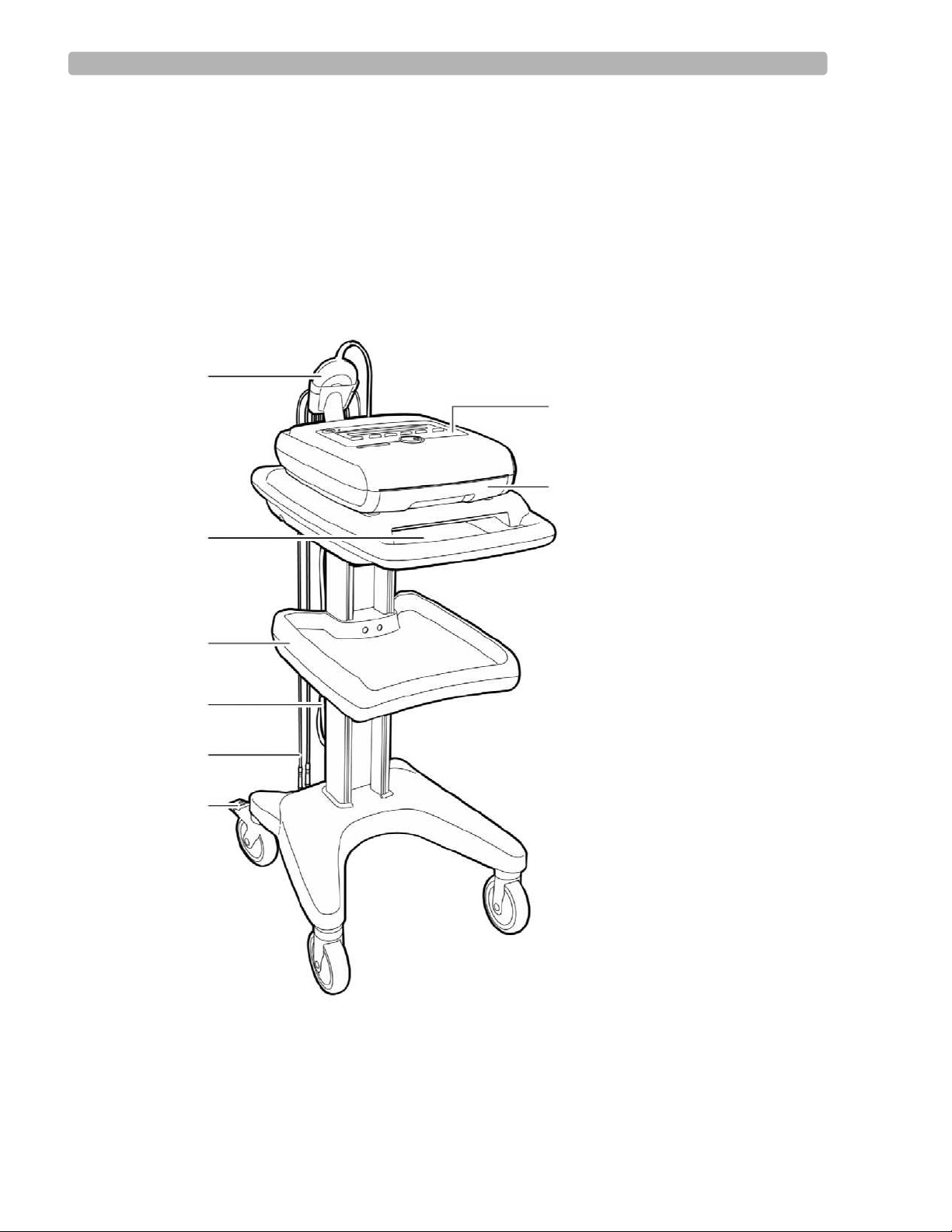
Figure 1-1 PageWriter Trim I Cardiograph and Cart (Front View)
A
G
H
B
C
D
E
F
A Patient Interface Module (PIM) E PIM Leads
B Printer paper/report storage slot F Wheel Brake
C S torage Shelf G Control Panel
D AC Power Cord H Printer Paper Drawer
1-6 PageWriter Trim Cardiograph Service Manual
Page 15
Introduction Tour of PageWriter Trim Cardiographs
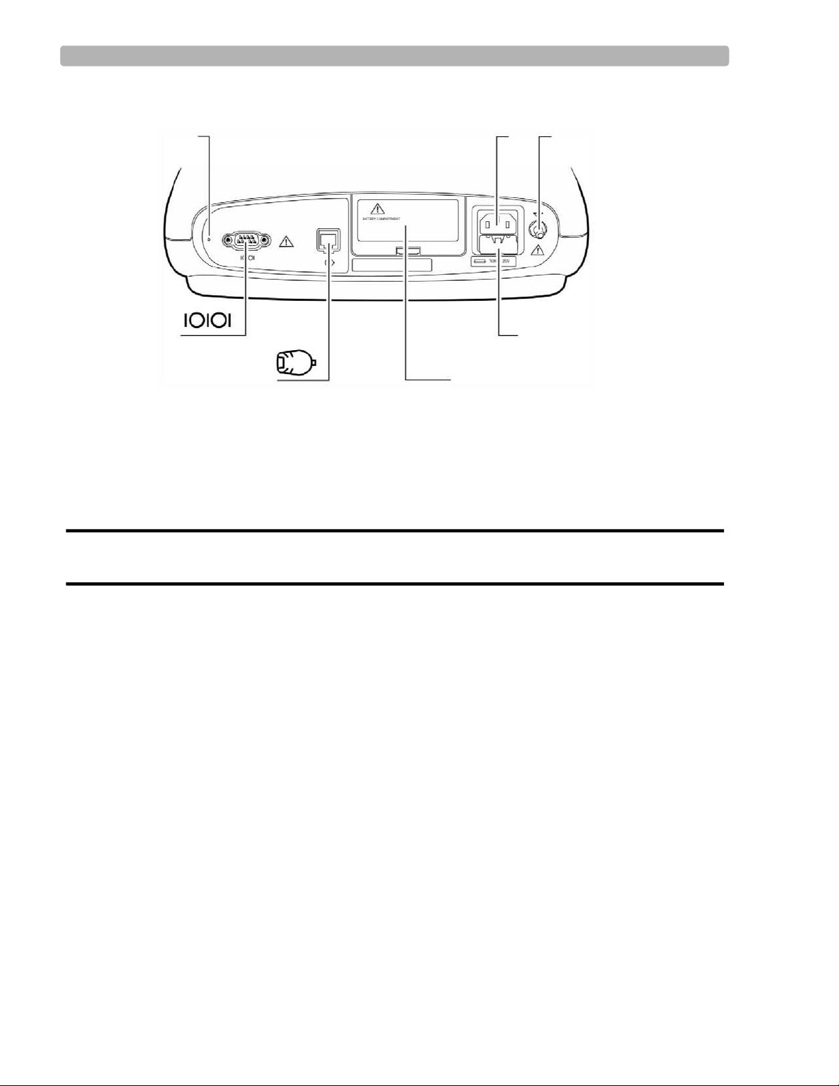
Figure 1-2 PageWriter Trim I Cardiograph (Rear View)
I
ML
J
KN
I AC Power Cord Connector L Battery Door
J Equipotential Post M PIM Connector
K Fuse Door N Serial Connector (not supported)
WARNING Do not connect a LAN cable connector to the PIM connector.
Do not plug a telephone connector into the PIM connector.
PageWriter Trim Cardiograph Service Manual 1-7
Page 16
Introduction Tour of PageWriter Trim Cardiographs
PageWriter Trim II, III, and Rx Cardiograph
The following section shows front and rear views of the PageWriter Trim II, III and Rx
cardiographs. For additional details, see the PageWriter Trim Instructions for Use.
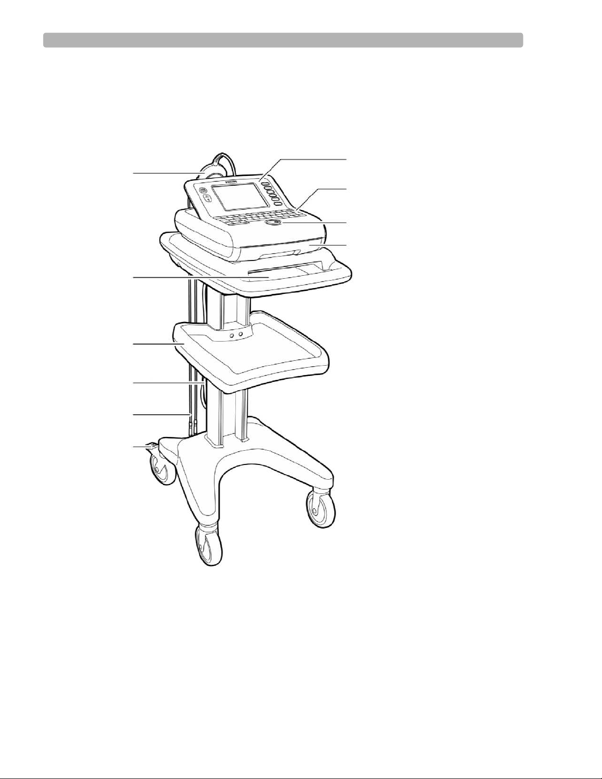
Figure 1-3 PageWriter Trim II, III, and Rx Cardiograph and Cart (Front View)
G
A
H
I
J
B
C
D
E
F
A Patient Interface Module (PIM) F Wheel Brake
B Printer paper/report storage slot G Control Panel
C Storage Shelf H Keyboard
D AC Power Cord I Trim Knob
E PIM Leads J Printer Paper Drawer
1-8 PageWriter Trim Cardiograph Service Manual
Page 17
Introduction Tour of PageWriter Trim Cardiographs
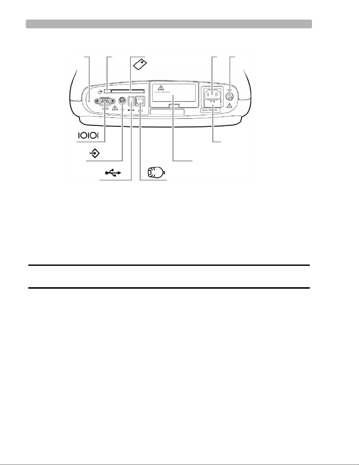
Figure 1-4 PageWriter Trim II, III, and Rx Cardiograph (Rear View)
KL
T
S
R
Q
P
M
N
O
K PC Card Eject Button P Battery Door
L PC Card Slot Q PIM Connector
M AC Power Connector R SmartCard Reader (USB) Connector
N Equipotential Post S Barcode Reader or Magnetic Card Reader Connector
O Fuse Door T Serial Connector (not supported)
WARNING Do not connect the LAN cable connector into the PIM connector.
Do not plug a telephone connector into the PIM connector.
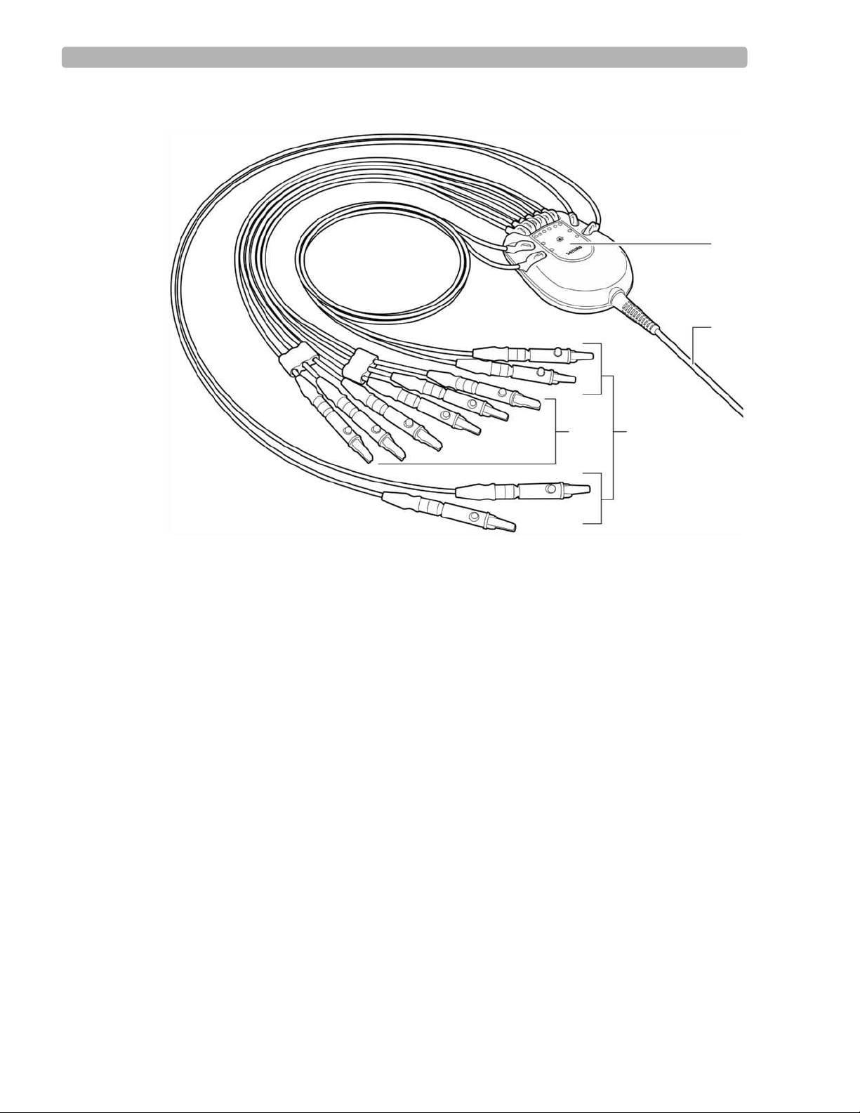
Patient Interface Module (PIM)
The Patient Interface Module (PIM) is a hand-held device that connects to the cardiograph.
The lead wires on the PIM attach to the electrodes placed on the patient. The exterior of the
PIM is labeled for quick and easy lead identification.
The PIM connects to the patient data cable and to the lead wires attached to the patient. See
Figure 1-5 on the following page.
For details about connecting the lead wires to the PIM, see the PageWriter Trim Instructions
for Use.
PageWriter Trim Cardiograph Service Manual 1-9
Page 18
Introduction General Service Information
Figure 1-5 Patient Interface Module
A
B
CD
A Lead Wire Labeling C Limb Lead Wires
B Patient Data Cable D Precordial (chest) Lead Wires
General Service Information
Keep the following points in mind when servicing this product.
Installation
The PageWriter Trim does not require installation by Philips field personnel. The cardiograph
can be installed by the customer. The PageWriter Trim Instructions for Use describes the
proper setup and configuration of the cardiograph and cart system.
Upgrades
Upgrades are available to add specific functionality to the device after purchase. These
upgrades are:
989803129931 Add Bar Code Reader
989803129941 Add Magnetic Card Reader
1-10 PageWriter Trim Cardiograph Service Manual
Page 19

Introduction General Service Information
989803129951 Add PCMCIA Network LAN card
989803129961 Add 'Smart' IC Card Reader
989803130061 PageWriter Trim Training CD
989803130081 PageWriter Trim Documentation CD
989803130091 Patient Module - AAMI
989803130101 Patient Module - IEC
989803130111 Cardiograph Cart - Basic
989803138021 Shielded LAN cable
Consult your sales representative, dealer, or distributor for the latest details.
Preventive Maintenance
The PageWriter Trim does not require scheduled preventive maintenance.
Preventive maintenance and periodic operational checks are intended to be performed by the
user. Both topics are covered in the Cardiograph Care and Maintenance chapter of the
PageWriter Trim Instructions for Use and this service manual. If further technical assistance is
required, contact the nearest Philips Response Center. See "Contacting a Philips Response
Center" on page 1-17.
Repair Philosophy
The repair philosophy of the PageWriter Trim Cardiograph is subassembly replacement.
Examples of subassemblies are the print-head assembly, LCD, the main Processor Circuit
Assembly (PCA), the power supply board, the power module, the printer drawer, etc.
Replaceable subassemblies are identified in Chapter 7, “Parts and Accessories”. Only Philips
authorized personnel can repair this product. Repairs by users that involve replacing
subassemblies and components are not supported.
PageWriter Trim Cardiograph Service Manual 1-11
Page 20

Introduction Ordering Supplies, Options and Accessories
Ordering Supplies, Options and Accessories
These tables list the options and accessories available for the PageWriter Trim family of
cardiographs, as well as ordering information for the supplies and accessories.
Country/Region Options
Country and region options includes the appropriate keyboard, power cord, printer paper,
patient leads, and language. The following table shows the configuration for the country and
region.
Table 1-1 Country/Region Option Configuration
Option
Country/
Region
Labels &
User Doc.
AB0 Taiwan Traditional
Chinese
AB2 China Simplified
Chinese
AB4 Singapore
English English US
& Hong
Kong
AB9 Portugal Portu-
guese
ABA USA/
English English US
Canada
(English)
ABB European
English English US
English
ABC Canada
French French European AAMI 8120(French)
Interp.
Rpt
Keyboard
English US
English
Chinese US
English
English
Portu-
European IEC 8120-
guese
English
English
PIM/
Lead
Version
Power
Cord
Opt.
AAMI 8120-
5429
IEC 8120-
8376
AAMI 8120-
1351
1689
AAMI 8120-
5429
IEC 8120-
1689
5429
Default
Paper
A
A4
A4
A4
A
A4
A
ABD Germany German German European IEC 8120-
ABE Spain Spanish Spanish European IEC 8120-
ABF France French French French IEC 8120-
ABG Australia English English US
1-12 PageWriter Trim Cardiograph Service Manual
English
1689
1689
1689
AAMI 8120-
4475
A4
A4
A4
A4
Page 21

Introduction Ordering Supplies, Options and Accessories
Table 1-1 Country/Region Option Configuration (continued)
ABH Nether-
lands
ABM Latin
American
ABU UK English English US
Dutch Dutch US
English
IEC 8120-
1689
Spanish Spanish European AAMI 8120-
5429
IEC
English
81201351
ABZ Italy Italian Italian European IEC 8120-
6978
AC4 Brazil Portu-
guese
Portuguese
European AAMI 8120-
5429
AC8 Argentina Spanish Spanish European AAMI 8120-
6869
ACJ India English English US
English
AKJ Israel &
Gaza
English English US
English
IEC 8120-
4211
IEC 8120-
5182
Strip
A4
A
A4
A4
A
A
A4
A4
AKV Chile &
others
Spanish Spanish European AAMI 8120-
6978
AR0 Japan Japanese Japanese Japanese IEC 8120-
4753
A
A4
PageWriter Trim Cardiograph Service Manual 1-13
Page 22
Introduction Ordering Supplies, Options and Accessories
Table 1-2 Options
Option Description
A01 PageWriter Trim Cardiograph and Cart System
A02 PageWriter Trim Cardiograph only
C11 Lan Card
C12 Bar Code Reader
C13 Magnetic Card Reader
C14 ‘Smart’ IC card reader
C15 Modem Card - U.S. and Canada only
C20 Interpretation (For Trim I only)
C30 PCMCIA Card ECG storage
Table 1-3 Documentation Part Numbers
Part Number Description
Quick Reference Card
Getting Started Guide
Instructions for Use
M4992-91905
Learning Products Folder
Standard Accessories
The standard accessories are based on model number and country/region options. See
"Country/Region Options" on page 1-12. Accessories include:
100 sheets of z-fold paper
– English paper p/n M3707A
– Metric paper p/n M3708A
Tab electrodes p/n 13943D
Alligator clips
– 989803129231 (AAMI)
– 989803129241 (IEC)
Quick Reference Card
Getting Started Guide
PageWriter Trim Learning Products Folder
1-14 PageWriter Trim Cardiograph Service Manual
Page 23

Introduction Ordering Supplies, Options and Accessories
Supplies and Ordering Information
The part numbers for all supplies for the PageWriter Trim cardiograph are listed in this
section.
NOTE This section describes supply part numbers only. For repair part numbers, see Chapter 7, “Parts and
Accessories”.
You can order all supplies on the World Wide Web at
http://shop.medical.philips.com
Use the part numbers listed in this section for reference to ensure that the correct supplies are
ordered.
Table 1-4 Complete Lead Sets
Part Number Description
989803129161 Complete Lead Set (AAMI)
989803129191 Complete Lead Set (IEC)
Table 1-5 Replacement Lead Sets and Accessories
Part Number Description
989803129141 Limb Lead Set, 99 cm/39 in (AAMI)
989803129151 Chest Lead Set, 61 cm/24 in (AAMI)
989803129171 Limb Lead Set, 99 cm/39 in (IEC)
989803129181 Chest Lead Set, 61 cm/24 in (IEC)
989803129201 Long Limb Lead Set, 137 cm/54 in (IEC)
989803129211 Long Chest Lead Set, 99 cm/39 in (IEC)
989803129221 Long Complete Lead Set (IEC)
989803129231 Alligator Clips for Disposable Tab Electrodes (AAMI)
989803129241 Alligator Clips for Disposable Tab Electrodes (IEC)
PageWriter Trim Cardiograph Service Manual 1-15
Page 24

Introduction Ordering Supplies, Options and Accessories
Table 1-6 Electrodes
Part Number Description
13943B Disposable cardiography electrode, resting diagnostic ECG
M2253A Disposable electrode, adult, resting ECG (not available in
Japan)
M2254A Tab electrode adapter
40431B Alligator Clip Adapter for 1/8 post
40498E Snap Lead Electrode (IEC)
40475A Snap Lead Electrode Adapter
40490E 15mm Suction Electrode
40421A Push-in Connect Welsh Electrode
40494E Limb Clamp Electrode C400 (4 per box)
40491E Limb Plate Electrode C400 (4 per bag)
40424A Limb Plate Electrode (4 pack)
14030A Strap Electrode, 14 inch limb (4 per pack)
40420A Disposable electrode, diagnostic, pre-gelled
13944B Wet Gel Foal Electrode, resting ECG
Table 1-7 Printer Paper
Part Number Description
M3707A Thermal Paper (100 sheets), A size (8.5 x 11 in/21.6 x 28 cm)
M3708A Thermal Paper (100 sheets), A4 size (8.27 x 11.69 in/21 x 29.69
cm)
Table 1-8 Battery
Part Number Description
989803130151 Battery
1-16 PageWriter Trim Cardiograph Service Manual
Page 25

Introduction Contacting a Philips Response Center
Contacting a Philips Response Center
The Philips Response Center can assist with product troubleshooting and provide technical
expertise to help with any issue with the PageWriter Trim cardiograph or any of its
accessories.
For more information on the Philips Response Center go to
www.medical.philips.com/main/services/response_center
North America Response Centers
Country Telephone Number
Canada (800) 323 2280
United States (800) 548-8833
Europe Response Centers
Country Telephone Number
United Kingdom 07 002 432 58 472 or
07 002 HEALTHRC
Austria 01 25125 333
Belgium 32 2 525 7102 (French)
32 2 525 7103 (Flemish)
Finland 010 855 2455
France 0803 35 34 33
Germany 01850 475000
Italy 0800 8256087
Netherlands 31 4 027 876 30
Spain 34 90 2 304 050
Sweden 08 5064 8830
Switzerland 0800 80 10 23
PageWriter Trim Cardiograph Service Manual 1-17
Page 26

Introduction Other Resources
Asia Pacific Response Centers
Country Telephone Number
Australia 1800 251 400
China 800 810 0038
Hong Kong 852 2876 7578
Macau 0800 923
India
New Delhi
Mumbai
Calcutta
Chennai
Bangalore
Hyderabad
011 2695 9734
022 5691 2643/2431
2485 3718
044 555 01000
080 5091 911
040 5578 7974
Japan 0120 381 557
Korea
Seoul
080 372 7777 (toll free)
02 3445 9010
Singapore 1800 Philips
New Zealand 0800 251 400
Philippines 02 845 7875
Malaysia 1800 886 188
Thailand 02 614 3569
Indonesia 021 794 7542
Taiwan 0800 005 616
Other Resources
For additional information on the PageWriter Trim cardiograph, see:
PageWriter Trim Cardiograph Getting Started Guide
PageWriter Trim Instructions for Use
PageWriter Trim Cardiograph Interactive Training Program
1-18 PageWriter Trim Cardiograph Service Manual
Page 27

2
Chapter 2Theory of Operation
This chapter provides functional descriptions of the components of the PageWriter Trim
Cardiograph. These descriptions are at the functional-block level. This chapter also provides a
system-level interconnection schematic, a data flow schematic, and a power-system block
diagram.
This chapter is organized into the following sections:
System Overview. . . . . . . . . . . . . . . . . . . . . . . . . . . . . . . . . . . . . . . 2-1
Hardware Logical View. . . . . . . . . . . . . . . . . . . . . . . . . . . . . . . . . . 2-2
High Level ECG Data Flow and Storage . . . . . . . . . . . . . . . . . . . . 2-4
Power System Overview. . . . . . . . . . . . . . . . . . . . . . . . . . . . . . . . . 2-8
Power Management. . . . . . . . . . . . . . . . . . . . . . . . . . . . . . . . . . . . 2-10
Except as noted, the information in this chapter applies to the PageWriter II/III/Rx and the
PageWriter I.
System Overview
The PageWriter Trim system performs acquisition, analysis, printing, storage, and transfer of
ECG waveforms and other patient clinical data.
The PageWriter Trim Consists of three major subsystems:
Main controller
An Intel StrongArm-base single-board computer (SBC) with extensive I/O facilities,
running Windows CE 4.1. The PageWriter Trim application software runs on the main
controller, which includes the display and user-input subsystems.
Print controller
A Motorola Coldfire-based control circuit, embedded in the main controller board that
provides all the real-time management of the printer. The print controller communicates
with the main controller through USB.
Patient Interface Module (PIM)
An Intel StrongArm-based controller running Windows CE 4.1, coupled with a signal
acquisition board employing Philips proprietary mixed-signal ASIC technology for ECG
acquisition. The PIM communicates with the main controller through USB.
2-1
Page 28
Theory of Operation Hardware Logical View
Hardware Logical View
Control of the PageWriter Trim is provided by application software running on the main
control board, interacting with numerous hardware and software subsystems. The following
are high-level descriptions of these various subsystems.
Main Control Board
The main control SBC contains loader software and the Windows CE kernel image in its
internal flash memory (32 MB for PageWriter Trim II/III/Rx, 16MB for PageWriter Trim I).
At system boot, a system RAM test is performed by the loader (onboard RAM is 64MB), and
then the Windows CE kernel loads. When Win CE loads, the application launcher runs,
verifying system and executable images before loading the Ruby application. For PageWriter
Trim II/III/Rx, all interaction with the operator is through the Ruby300_APP application. For
PageWriter Trim I, all interaction with the operator is through the Ruby100_APP application.
The application software is stored in internal Flash memory. For PageWriter Trim II/III/Rx,
ECG archives are stored on a separate 128MB CompactFlash (CF) card installed in the main
control board.
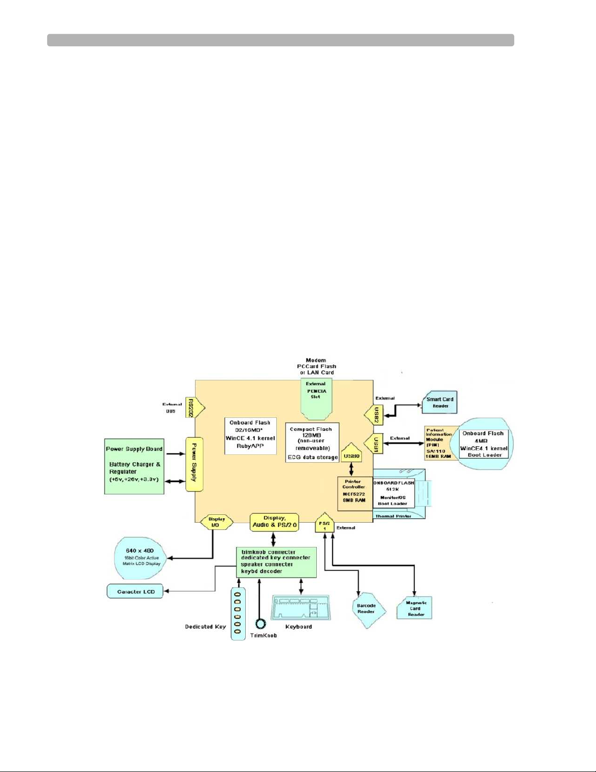
The following shows devices and interfaces provided by the main control board.
Figure 2-1 Devices and Interfaces for Main Control Board
2-2 PageWriter Trim Cardiograph Service Manual
Page 29

Hardware Logical View Theory of Operation
The board presents a backplane through the back of the PageWriter Trim case, allowing the
user to access interfaces labeled as external above, along with the PCMCIA slot, and the PS/2
connection for a barcode reader device.
Display
The PageWriter Trim II/III/Rx display is 640 x 480 pixels, up to 64 color TFT LCD with
backlight. All display functions are handled by the main control board using the S1D13506
(EPSON) graphics accelerator chip.
The PageWriter Trim I display is a 40 x 2 Line Character LCD with cursor. Its function is
driven directly by SA1110.
Patient Interface Module (PIM)
The PIM is a SA1110-based WinCE subsystem, which is connected by USB to the main
control board. It provides real-time data acquisition of ECG signal from an electrode
connected patient.
Printer Control (USB)
All data printing is handled by the Main Board. The printer control is a Motorola Coldfire
processor-based control circuit. It provides ECG waveform rendering and basic bitmap
imaging operations, and uses a PCL-like control language API for page description and feed
control.
Battery (Lead-Acid)
The battery is a lead-acid 12 volt unit, providing 2.9 Amp-Hours of current when fully
charged.
Keyboard/Trim Knob (PS/2)
The PageWriter Trim II/III/Rx cardiograph includes a laptop-format, PS/2, sealed, full key
action keyboard, a Trim Knob as a pointing device for easy navigation, and six dedicated keys.
It includes a keyboard matrix, Trim Knob decoder, and daughter board, which provides
language-specific keyboard support and decoding via PS/2 and standard WinCE device
drivers for key and Trim Knob input into PageWriter Trim. Powered by PS/2 connection.
The PageWriter Trim I cardiograph includes six dedicated keys and a Trim Knob. The
dedicated keys and the Trim Knob interface to the Main Board via the PS/2 port.
PageWriter Trim Cardiograph Service Manual 2-3
Page 30

Theory of Operation High Level ECG Data Flow and Storage
Magnetic Card Reader (PS/2)
A magnetic card reader is available as an option. It connects through an external PS/2
connector and provides ISO and standard encoded magnetic strip support. Manual removal
and insertion is required.
NOTE The PS/2 port is not a plug-and-play port. You must attach the barcode reader to the port before
powering on the unit.
Barcode Reader (PS/2)
A barcode scanner is available as an option. It connects through an external PS/2 connector
and provides standard barcode scanning capability. It emulates a keyboard, allowing scanned
codes to be presented to the PageWriter Trim cardiograph as if they had been typed on the
standard keyboard, powered by PS/2 connection. The barcode reader can be configured using
special barcodes.
NOTE The PS/2 port is not a plug-and-play port. You must attach the barcode reader to the port before
powering on the unit.
Smart Card Reader
A smart card reader is available as an option. It connects through an external USB connector
and provides standard smart card reading capability. PageWriter Trim cardiograph uses the
smart card reader to get patient information.
PCMCIA LAN Card
A PCMCIA LAN Card is available as an option. It connects through the PCMCIA slot and
provides standard LAN capability. The PageWriter Trim cardiograph communicates with the
TraceMaster ECG Management System through the PCMCIA LAN Card.
PCMCIA Modem Card
A PCMCIA modem card is available as an option. It connects through the PCMCIA slot and
provides standard modem capability. PageWriter Trim faxes ECG data to remote receivers or
communicates with TraceMaster ECG Management System through the PCMCIA modem
card.
High Level ECG Data Flow and Storage
General ECG flow begins with acquisition by the Patient Interface Module (PIM) from
electrodes placed on a patient. Data is streamed real-time to the main control board, where it is
received into the application buffers in RAM. These buffers are used to present the signal data
on the real-time screen. When the user initiates an auto report print, corresponding 10-second
segments of the signal data are then copied to the temporary ECG storage memory in RAM.
2-4 PageWriter Trim Cardiograph Service Manual
Page 31

High Level ECG Data Flow and Storage Theory of Operation
These 10-second segments are named ECG reports that can be previewed and printed. In the
case of Auto mode, the ECG report is automatically printed. An ECG report contains signal
data, analysis information, patient demographics, and acquisition information, along with
operator and device information. See the PageWriter Trim XML documentation for a
complete description of the contents of the ECG data record.
If automatic save after print is set, the ECG report is saved in XML format to the internal main
archive. This archive is non-volatile and resides on the internal CompactFlash (CF) card.
Index files with a CDB extension are also maintained in this archive.
From the internal main archive, the ECG XML data format files can be copied, deleted,
previewed, printed, and transferred to other devices. The internal main archive cannot receive
ECG XML files from external devices. Retrieved ECG file storage is limited to the internal
remote archive.
NOTE PageWriter Trim-generated ECG XML files comply with the Philips Medical Systems ECG XML
Schema version. They incorporate an embedded CRC32 value, which is used to ensure the data
integrity of the file.
Figure 2-2 ECG Flow and Storage
PageWriter Trim Cardiograph Service Manual 2-5
Page 32

Theory of Operation High Level ECG Data Flow and Storage
Internal Main Archive
The internal main archive resides on the internal CompactFlash (CF) card, and is used as the
primary ECG data repository. ECG XML files and related index files are stored here in the
RubyArchiveInternal directory. All stored ECG files transition through this archive prior to
transfer or copying to other devices, such as the PC card.
Currently, the internal main archive is limited to storing the following maximum number of
ECGs.
Table 2-1 Maximum Number of ECGs Stored (Internal Main Archive)
Model
Maximum Number of ECGs
Stored
Trim Rx 200
Trim III 150
Trim II 50
Internal Remote Archive
The internal remote archive resides on the internal CompactFlash (CF) card much like the
internal main archive. All XML files retrieved from remote sites, such as the TraceMaster
ECG Management system, reside in this archive until deleted. ECG XML files and related
index files are stored in the RubyArchiveRemote directory.
Currently, the internal remote archive is limited to a maximum of 100 ECGs.
External PC Card Archives
The external PC card archives reside on a compatible PC card inserted into the PC card slot.
Files may then be transferred to inserted cards using the Archive mode features of the
PageWriter Trim, and are stored as an XML format. An index file is created and maintained on
each PC card when CDB files are transferred or copied from the card. Currently, an external
PC card archive is limited to storing the following maximum number of ECGs.
Table 2-2 Maximum Number of ECGs Stored (External PC Card)
Model
Maximum Number of ECGs
Stored
Trim Rx 200
Trim II/III 150
NOTE When you add or delete compatible ECG XML files from a PC card (not using the PageWriter Trim),
it is recommended that you delete all CDB files prior to reinserting the PC card into the PageWriter
Trim. In the absence of an index file, the PageWriter Trim automatically regenerates the index based
on the XML files on the PC card.
2-6 PageWriter Trim Cardiograph Service Manual
Page 33

High Level ECG Data Flow and Storage Theory of Operation
Rendered ECG Report Prints
A rendered ECG report print is a representation of the ECG data. This includes a highresolution print of the signal data, and may include configured patient demographics,
acquisition information, and other non-signal data elements.
The PageWriter Trim allows the user to customize the fields on an ECG report print. The
report print may consist of one or more continuous pages on perforated thermal media from
the printer.
Figure 2-3 Rendered ECG Report Print Sample
Fax-Rendered ECG Report Print
A fax-rendered ECG report print is equivalent to the rendered ECG report print, as described
in the previous section, except it has been adjusted to comply with fax transmission and
resolution device requirements. When the user starts a fax transfer, the ECG report is rendered
and transmitted to a remote fax site pre-configured into the unit, using the optional fax and
modem PC card. The fax-rendered ECG report print may be stored on the received system end
as an electronic file, and not actually used to produce a printed copy.
PageWriter Trim Cardiograph Service Manual 2-7
Page 34

Theory of Operation Power System Overview
Power System Overview
The PageWriter Trim power system consists of:
A 65-watt AC/DC medical grade power module
One 12 volt, 2.9 amp-hour lead-acid rechargeable battery
A power supply board which includes battery charging circuitry, various voltage
regulators, and logic circuitry to provide for battery operation
The PageWriter Trim is designed to run primarily on battery power, using the AC power for
recharging. The power board has a battery charging chip to control the battery charging. The
main board has an A/D converter to monitor voltage of every power supply and a Board Status
Register (BSR) to monitor the battery charging status.
The major power draws within the PageWriter Trim are the LCD display backlights, which
can draw up to 4 watts, and the thermal printer, which can draw about 48 watts. Provisions
have been incorporated into the PageWriter Trim to allow the user to modify the display
brightness. To extend battery life, set the display brightness to low or medium level. Also,
activate the power save mode (dims the screen) to further extend battery life. The printer
control board is current limited for normal printing. However, if print demand is too high, the
current limiter will not print the output, resulting in a faded page.
Battery
The 12V recharged sealed lead-acid battery provides the power to the PageWriter Trim. The
battery provides a high-current discharge as needed for thermal printing. Built-in protection
circuitry in each pack prevents damage to the battery by overcharging, over discharging, over
current, and over temperature.
2-8 PageWriter Trim Cardiograph Service Manual
Page 35

Power System Overview Theory of Operation
Figure 2-4 Power System Block Diagram
AC Input
AC
DC
DC Output
Charger
Power Labels
Battery Pack
Battery
Voltage
Power Board
Charger
Status
On/OFF
Contol
+5VP
+3.3V
+3.3
VB_P
Vcore
(+1.86v)
VPH
(+26V)
Main Board
A/D
monitor
Power Supply Con
d
r
a
o
B
n
i
a
M
o
t
r
e
w
o
P
e
d
i
v
o
r
P
The following represent the various power labels used in the PageWriter Trim.
Vin
The DC voltage direct from the AC power. The voltage level is between 17.10V and 1 8.9 0V,
with a maximum power output of 65 watts. This voltage is monitored.
VB+_T (Battery information)
The battery voltage range is between 10.0V and 14.8V. Discharge current is limited to a
continuous 2.9 amps, with a 4.0 amp limit for short periods. This voltage is monitored.
VO
The voltage will be supplied by Vin and battery. Its range is between 10.0V to 18.90V. The
voltage is monitored.
PageWriter Trim Cardiograph Service Manual 2-9
Page 36

Theory of Operation Power Management
+3.3V
Output from the U113 (power board) regulator. This switching regulator will supply 3.3V at
up to 4.25A of current. This voltage is monitored.
+3.3VB_P
Output from U111 (power board) regulator, an MIC5233, for the real timer and power
sequence circuit. The voltage level is 3.3V, and can provide up to 100mA of current. This
voltage is not monitored.
VDDX
Output from +3.3V through a filter, which is the primary power for the main system
processors and memory. The voltage level is 3.3V. This voltage is monitored.
π
Vcore (+1.86V)
Output from the U105 (power board) circuit, an LTC1627, which is 1.86V core power for the
main system processor. The input to this regulator is from the 3.3V supply, and can supply up
to 500mA of current. This voltage is monitored.
+5VP
Output from the U101(power board) circuit, an LTC1374, which supplies all the 5.00V power
to the system. Input is from V0, and output is 5.00V with a maximum current of 4A. This
voltage is monitored.
USB_VCC
Output from the U303 (main board) circuit, an MIC2503, which supplies the barcode scanner
and other external USB device. Input is from +5V, and output is +5V with maximum current
of 500mA. This voltage is monitored.
VPH
Output from the U108 (power board) circuit, an LM2588, which supplies +26V power to the
printhead. It is controlled by printer MCU, MCF5272, which is located on main board. VPH
provides power only when a print session starts. Otherwise, VPH does not provide power. This
voltage is monitored by MCF5272.
Power Management
Battery Charging Logic
The system host processor controls several functions of the power system. These include:
Activating sleep mode if no activity is detected for a preset period of time.
Restricting the user from printing when the charge capacity reaches preset levels.
2-10 PageWriter Trim Cardiograph Service Manual
Page 37

Power Management Theory of Operation
Alerting the user when maintenance is needed for the battery.
Battery Gauge
The battery gauge on the PageWriter Trim II/III/Rx LCD display consists of four segments.
When the battery is fully charged, all four segments are displayed.
The battery gauge on the PageWriter Trim I LCD display consists of two icons. It shows in the
upper right corner of the LCD.
The following table shows the different battery status readings.
Table 2-1 Battery Status Readings
Battery Level
Full Charge battery
75%
50%
Low Battery
Flashing Lo w Batt er y
No or Dead Battery
Battery is charging
Bars (Trim II/III/Rx) Icons (Trim I)
Flashing
Flashing
&
Moving bar
&
Flashing
&
Battery Discharging
When the battery is discharged to the 30% level, the PageWriter Trim disables high-demand
printing, and continues to allow the battery to be discharged to a 20% level. When the 20%
level is reached, the PageWriter Trim disables printing, and warns the user to plug in the AC
power cord. If the AC power cord is not plugged in within three minutes, the PageWriter Trim
automatically shuts down.
PageWriter Trim Cardiograph Service Manual 2-11
Page 38

Theory of Operation Power Management
Battery Charging
When the AC power cord is plugged in, the battery begins to charge. Check the charging
status on the Board Status Register (BSR).
Charge Current
When the unit is in operating mode, the charge current is 580mA. When the unit is in sleep
mode, the charge current depends on the battery. The initial charge is approximately 580mA in
bulk charger status. When the voltage is up to approximately 14.6V, the current is slowly
reduced to approximately 100mA over time as it enters floating charging.
Battery Information
Battery information is sent from the battery charger, UC3909. This information is then sent up
to the host processor via BSR, and can be viewed from the Service Utility screen.
2-12 PageWriter Trim Cardiograph Service Manual
Page 39

3
Chapter 3Cardiograph Care and Maintenance
This chapter contains information on basic cardiograph care and periodic maintenance. If
further technical assistance is required, contact the nearest Philips Response Center
(see page 1-17). The PageWriter Trim does not require scheduled preventive maintenance.
Basic cleaning and maintenance guidelines are also included in the Maintenance chapter of the
PageWriter Trim Cardiograph Instructions for Use.
This chapter is organized as follows:
Cleaning the Cardiograph . . . . . . . . . . . . . . . . . . . . . . . . . . . . . . . . 3-1
Cleaning the Print Head . . . . . . . . . . . . . . . . . . . . . . . . . . . . . . . . . 3-3
Replacing the Printer Paper. . . . . . . . . . . . . . . . . . . . . . . . . . . . . . . 3-3
Battery Maintenance and Care . . . . . . . . . . . . . . . . . . . . . . . . . . . . 3-4
Replacing the Lead Wires in the PIM. . . . . . . . . . . . . . . . . . . . . . . 3-6
Cardiograph and Accessory Disposal . . . . . . . . . . . . . . . . . . . . . . . 3-7
Setting the Date and Time. . . . . . . . . . . . . . . . . . . . . . . . . . . . . . . . 3-7
Maintenance Tests . . . . . . . . . . . . . . . . . . . . . . . . . . . . . . . . . . . . . . 3-9
Cleaning the Cardiograph
To clean the cardiograph
Unplug the AC power cord.
1
2 Wipe the external surfaces of the cardiograph with a soft cloth dampened in any of the
approved cleaning solutions listed below.
CAUTION When cleaning, avoid the lead wire connectors and patient data cable connectors.
Approved Cleaning Solutions
Mild soap and water
Isopropyl alcohol
3-1
Page 40

Cardiograph Care and Maintenance Cleaning the Cardiograph
CAUTION D o n o t use strong solvents or abrasive cleaning materials.
Do not spill liquids on the surface of the cardiograph.
Do not use any of the following to clean the cardiograph:
Acetone
Iodine-based cleaners
Phenol-based cleaners
Ethylene oxide sterilization
Chlorine bleach
Ammonia-based cleaners
The cardiograph or PIM should not be autoclaved, ultrasonically cleaned, or immersed,
Cleaning the PIM, Patient Data Cable, and Lead Wires
CAUTION Do n o t :
Use isopropyl alcohol
Autoclave the patient data cable or lead wires or use ultrasonic cleaners
Immerse
Use abrasive materials
Wet the connectors
To clean the PIM, patient data cable, and lead wires
1
Dampen a soft cloth with soapy water or with one of the disinfectants or cleaning agents
listed below. Clean patient data cable and lead wires with any of the following:
– Cidex Ortho Phthaladehyde
– Cetylcide
– Vesphene 2 Aqueous Phenolic Germicidal Agent
2 Wring excess moisture from the cloth before cleaning.
3-2 PageWriter Trim Cardiograph Service Manual
Page 41

Cardiograph Care and Maintenance Cleaning the Print Head
Cleaning the Print Head
A dirty print head may cause poor or uneven print quality.
TIP Clean the print head more frequently when printing large volumes of ECGs.
Figure 3-1 Paper Drawer and Print Head
To clean the print head
1
Pull the paper drawer completely out from the front of the cardiograph.
2 Turn the unit over.
3 Wipe the print head lightly with a foam swab dipped in 90% alcohol.
4 Allow the print head to dry.
Replacing Printer Paper
Replace the printer paper when a red stripe appears on the printed ECG report. Only use
Philips Medical Systems replacement printer paper. For part number and ordering
information, see page 1-16.
Always load less than 100 sheets of printer paper into the paper tray
Ensure that the entire first page of the new paper roll is fully draped over the roller before
closing the printer door
PageWriter Trim Cardiograph Service Manual 3-3
Page 42

Cardiograph Care and Maintenance Battery Maintenance and Care
PageWriter Trim II and III:
Ensure that the paper size configured for the cardiograph is the same size paper being
loaded into the paper drawer.
Figure 3-2 Changing Printer Paper
A
A Paper sensor hole
To change the printer paper:
Open the paper drawer on the front of the cardiograph and remove any remaining sheets.
1
2 Insert a new pack of printer paper with the printed side facing up. Ensure that no more
than 100 sheets are being inserted into the paper tray.
3 Ensure that the paper sensor hole (A) is positioned as shown in Figure 3-2.
4 Drape the entire first sheet over the roller. Ensure that the perforated edge of the paper
aligns with the edge of the paper drawer.
5 Close the paper drawer.
6 Tear off the first sheet as shown in Figure 3-2.
Battery Maintenance and Care
Caring for the Battery
The battery must be installed for proper operation of the cardiograph. The cardiograph cannot
print an ECG report without the battery, even if it is plugged into AC power. For information
about removing or replacing the battery, see Chapter 6, “Removing and Replacing
Cardiograph Components”.
3-4 PageWriter Trim Cardiograph Service Manual
Page 43

Cardiograph Care and Maintenance Battery Maintenance and Care
The sealed lead-acid battery used in the PageWriter Trim family of cardiographs will provide
optimum life when the unit is continuously connected to AC power and fully charged after
each use. A depleted battery requires 16 hours of continuous charge time to fully charge.
Because it is not always possible to allow a full charge cycle between uses, the cardiograph
was designed to charge a depleted battery to 90% of its capacity in approximately eight hours.
CAUTION Repeated undercharging of the battery will damage the battery and reduce battery life.
NOTE Philips recommends that the cardiograph be plugged into AC power whenever possible to maximize
battery life.
Battery life varies depending on frequency of use and maintenance. For improved battery life,
keep the cardiograph plugged in when not in use. If the battery has been fully charged and
requires recharging after a few ECGs, consider replacing it.
For optimal battery performance:
Only use Philips Medical Systems lead-acid battery (Philips part number 989803130151
with the cardiograph.
Keep the cardiograph plugged in when not in use.
If the battery has been fully charged and requires recharging after a few ECGs, consider
replacing it.
The use of cardiograph accessories (bar code reader, magnetic card reader, PC card,
modem) will deplete battery power at a faster rate. The battery will require more frequent
charging if these accessories are used with the cardiograph.
NOTE The battery should be removed from the unit and placed in storage if the cardiograph will not be used
for more than one month.
Storing the Battery
Remove the battery from the cardiograph if it will be stored for more than 30 days without use.
While in storage, the battery will require a full recharge every 6 months. Charge the battery for
at least 16 hours. This will ensure that the battery does not completely discharge while in
storage. The battery life will be prolonged when stored in cooler temperatures, but will be
damaged if stored below freezing (0
o
40
C (104o F) or lower.
To store the battery:
Charge the battery for 16 hours before removing it from the cardiograph. Ensure that the
1
AC power cord is connected to the cardiograph and is plugged into a grounded AC power
outlet. Check that the green AC power indicator light on the front of the cardiograph is lit.
o
C/32oF). Store the battery at a temperature of
2 Remove the battery from the cardiograph and store it in a cool, dry location. For
information about removing or replacing the battery, see Chapter 6, “Removing and
Replacing Cardiograph Components”.
3 Recharge the battery for 16 hours for every 6 months that the battery is in storage.
PageWriter Trim Cardiograph Service Manual 3-5
Page 44

Cardiograph Care and Maintenance Replacing the Lead Wires in the PIM
Replacing the Lead Wires in the PIM
To replace the lead wires
Disconnect the PIM from the RJ-11 receptacle (rear of cardiograph).
1
2 Remove the lead wire(s) by pulling the connector up.
3 Match the lead wire labeling (on lead) with the same lead wire connector on the PIM.
Replace the lead wire by snapping it into the connector.
3-6 PageWriter Trim Cardiograph Service Manual
Page 45

Cardiograph Care and Maintenance Cardiograph and Accessory Disposal
4 Reattach the patient data cable to the RJ-11 receptacle (rear of cardiograph).
WARNING To ensure safety and prevent damage to the system, only connect the patient data cable
to the correct PIM connector on the rear of the cardiograph.
Cardiograph and Accessory Disposal
When the cardiograph has reached the end of its product life, dispose of it according to local
ordinance. When any of the cardiograph accessories reach the end of their product life, dispose
of these items in accordance with manufacturer instructions and local ordinances.
Setting the Date and Time
PageWriter Trim II/III/Rx
To change the date and time
1
Turn the Trim Knob and select the Config button on the Comman d Toolbar.
2 Push the Trim Knob. The Configuration screens appear.
3 Hold down the Alt key on the keyboard.
4 Press the L key. The Locale screen appears.
5 The Year: drop-down list is highlighted. Push the Trim Knob to display the drop-down
list.
6 Turn the Trim Knob to highlight the current year.
7 Repeat the procedure to set the current Month, Day, Hour, Minute, and Second.
PageWriter Trim Cardiograph Service Manual 3-7
Page 46

Cardiograph Care and Maintenance Setting the Date and Time
NOTE The Hour: is set on a 24-hour clock. If the Regional Settings are set to display a 12-hour clock, the
cardiograph will display the time based on the 12-hour clock setting.
8
Turn the Trim Knob to highlight the Apply Changes button.
9 Push the Trim Knob to apply the new date and time settings.
To change regional settings
1
Turn the Trim Knob until the Region drop-down list under Regional Settings is
highlighted.
2 Push the Trim Knob to display the drop-down list of available regional settings.
NOTE The Regional Settings only change the displayed time, date, and decimal formats.
3
Push the Trim Knob to select a regional setting. The regional settings appear on the screen.
To change the units system
Turn the Trim Knob to highlight a setting under Units System.
1
2 Turn the Trim Knob to highlight Metric or English.
3 Push the Trim Knob to select the setting.
Press Enter (on the keyboard) to save the changes and exit the Configuration screen. The new
changes are applied.
PageWriter Trim I
To change the date and time
1
Turn the Trim Knob until the date is highlighted.
2 Press the Trim Knob. A new screen appears showing the current date and time settings.
3 Turn the Trim Knob until the field you want to change is highlighted.
4 Press the Trim Knob to select the field.
5 Turn the Trim Knob to scroll through the options for that field.
6 Push the Trim Knob to select a setting.
7 Repeat the procedure to set the current Month, Day, Year, Hour, Minute, and Second.
8 When all settings are complete, turn the Trim Knob to highlight the arrow icon (»).
9 Push the Trim Knob to save the settings and to exit the screen.
3-8 PageWriter Trim Cardiograph Service Manual
Page 47

Cardiograph Care and Maintenance Maintenance Tests (Trim II/III/Rx)
Maintenance Tests (Trim II/III/Rx)
To verify or optimize cardiograph performance, use the diagnostic utilities and maintenance
tests. From the operation mode, you can use the tests listed below as a first step in identifying
a technical problem.
.
To open the Diagnostics/Maintenance Test screen
1
Turn the Trim Knob to highlight the Config button on the Command Toolbar.
2 Push the Trim Knob to select the button. The Configuration screen appears.
3 Select System by holding down the ALT key and selecting S on the Configuration Screen.
The
Diagnostics section of the screen lists the five maintenance tests.
Appendix B, “Maintenance Tests” provides instructions for each test. Refer to the page
numbers in the list below to locate the tests you need to perform.
Test Page
PIM Test
Barcode Test B-2
Magcard Test
Printer Test
Network Test
B-2
B-3
B-3
B-5
PageWriter Trim Cardiograph Service Manual 3-9
Page 48

Cardiograph Care and Maintenance Maintenance Tests (Trim II/III/Rx)
3-10 PageWriter Trim Cardiograph Service Manual
Page 49

4
Chapter 4 Troubleshooting
This chapter provides information for localizing cardiograph problems to the subassembly
level. This information is designed for use with the cardiograph’s diagnostic se lf-te s ts to help
you efficiently repair the cardiograph with a minimum of equipment.
This chapter provides the following information:
Power On and Power Off Sequence . . . . . . . . . . . . . . . . . . . . . . . . 4-2
Troubleshooting Cardiograph Issues. . . . . . . . . . . . . . . . . . . . . . . . 4-4
Display Issues . . . . . . . . . . . . . . . . . . . . . . . . . . . . . . . . . . . . . . . . . 4-4
Keyboard/Trim Knob/Dedicated Key Issues . . . . . . . . . . . . . . . . . 4-6
Signal Acquisition Issues . . . . . . . . . . . . . . . . . . . . . . . . . . . . . . . . 4-7
Real Time Screen Issues . . . . . . . . . . . . . . . . . . . . . . . . . . . . . . . . . 4-8
Archive Screen Issues . . . . . . . . . . . . . . . . . . . . . . . . . . . . . . . . . . . 4-8
Printer Issues . . . . . . . . . . . . . . . . . . . . . . . . . . . . . . . . . . . . . . . . . 4-11
PC Card Issues. . . . . . . . . . . . . . . . . . . . . . . . . . . . . . . . . . . . . . . . 4-13
4-1
Page 50

Troubleshooting Power On and Power Off Sequence
Power On and Power Off Sequence
The following sequence of events occur during a normal warm or cold cardiograph boot.
Figure 4-3 Power On Sequence
4-2 PageWriter Trim Cardiograph Service Manual
Page 51

Troubleshooting Power On and Power Off Sequence
Figure 4-4 Power Off Sequence
PageWriter Trim Cardiograph Service Manual 4-3
Page 52

Troubleshooting Troubleshooting Cardiograph Issues
Troubleshooting Cardiograph Issues
The troubleshooting tables in this section help you to localize a fault and correct it.
The following charts list symptoms and the steps to follow to investigate and solve the
problem. Most steps can be performed without opening the unit. Several failure mode
symptoms may actually be hardware induced or triggered, and may require board replacement
or opening of the unit for inspection
Display Issues
Table 4-1 Display Issues
.
Symptom
Screen is dark and
shows no image
Possible Cause &
Investigation Step
Unit is in standby
Action: Press the On/
Standby
button on the
front display.
Contrast has been
adjusted to the lowest
degree
Power issue: AC cord
Action: Inspect AC
power connections.
Power issue: Battery
Action: Open battery
compartment door and
inspect battery condition.
Confirmation Solution
Confirm the unit wakes
up.
User training on proper
use of unit’s standby
mode.
Confirm there is faint
image in the LCD.
Push “Ctrl” and “Down
arrow” key simultaneously to adjust
contrast high enough.
AC is applied but AC
Power On indicator LED
is dark.
Ensure AC cord is not
damaged and is plugged
into appropriate live AC
power socket.
AC is not attached and the
Replace battery.
battery is plugged into the
cardiograph. Push the
on/standby button. The
screen remains dark.
Power issue: Supply AC is applied but AC
Power off mode failure With battery plugged in,
LCD panel failure Replace with a good LCD
4-4 PageWriter Trim Cardiograph Service Manual
Power On indicator LED
is dark.
AC cord and connection
are verified and are good.
the printer is making a
clicking sound every 6
seconds.
panel to see if it can light.
Unit must be serviced to
replace power supply.
Press rear reset button to
reboot unit.
Send to Philips for
repair.
Page 53

Troubleshooting Troubleshooting Cardiograph Issues
Table 4-1 Display Issues (continued)
Symptom
Screen shows CRC
check failure
A dialog shows software version information with black
ground
Possible Cause &
Investigation Step
LCD backlight board
failure.
Confirmation Solution
Replace with a good
backlight board to see if
the LCD can light.
Main controller board
failure
With the battery plugged
in, the printer is making a
clicking sound every 6
seconds. Reset button
does not reboot unit.
Application software is
damaged
Unit stops at the
‘COPYRIGHT’ screen
and a warning dialog pops
up with the message
‘CRC failed’.
File system is destroyed Unit stays on the black
screen. A dialog shows
software version
information, including the
loader & kernel version
and the PCMCIA storage
card status.
Send to Philips for
repair.
Send to Philips for
repair.
Send to Philips for
repair.
Send to Philips for
repair.
PageWriter Trim Cardiograph Service Manual 4-5
Page 54

Troubleshooting Troubleshooting Cardiograph Issues
Keyboard/Trim Knob/Dedicated Key Issues
Table 4-2 Keyboard/Trim Knob/Dedicated Key Issues
Symptom
Keyboard is
unresponsive
Keyboard is typing
incorrect characters
Possible Cause &
Investigation Step
Keyboard controller
subsystem has failed.
Keyboard controller
subsystem has failed.
Keyboard has Caps Lock
enabled.
Action: Inspect the
incorrect typed characters
on the display. If only the
case of the characters is
incorrect, press the Caps
Lock key .
Keyboard controller
subsystem has failed.
Confirmation Solution
Keyboard is still unresponsive.
Keyboard is now
functional.
Send to Philips for
repair.
Occasional recoverable
keyboard failures have
been observed. If failures persist, send to
Philips for repair.
Do the characters now
appear correctly?
Keyboard is now
functional.
Training on Caps Lock
use.
Occasional recoverable
keyboard failures have
been observed. If failures persist, send to
Philips for repair.
During upgrading, user
selects wrong keyboard
version for current locale.
Registry is lost.
4-6 PageWriter Trim Cardiograph Service Manual
Send to Philips for
repair.
Page 55

Troubleshooting Troubleshooting Cardiograph Issues
Signal Acquisition Issues
Table 4-3 Signal Acquisition Issues
Symptom
All leads show
leads off (red
dashed line)
continuously
One or more leads
show leads off
(red dashed line)
periodically
Possible Cause &
Investigation Step
PIM communications
have been lost for USB
connection failure.
PIM failure.
Action: Reset unit using
rear button.
Defib or high noise
event
Action: Observe
frequency and recovery
behavior.
Confirmation Solution
Unplug PIM from cardiograph, then plug it back
in. Wait about 10 seconds
Unplug PIM from cardiograph, then plug it back in.
Reset cardiograph.
to check the wave is
normal.
If the wave isn’t normal
yet, reset cardiograph and
see if the wave is normal.
Plug in a good PIM to
Replace with a good PIM.
confirm the waveform is
normal.
Leads off coincides with
electrode movement or
placement or defib event.
The PIM performs an
automatic ranging action
when input signals vary
significantly. If this behavior
persists, send to Philips for
repair.
One or more leads
show leads off
(red dashed line)
continuously
Electrode lead failure
Action: Attach ground
plate to leads and
observe lead status.
Confirm that the
physical connections
between the lead cables
and PIM are good and
the cables are
undamaged.
Electrode lead failure
Action: Attach ground
plate to leads and
observe lead status.
Confirm that the
physical connections
between the lead cables
and PIM are good and
the cables are
undamaged.
Lead(s) still showing
leads off periodically.
Lead(s) still showing
leads off.
Send to Philips for repair.
Send to Philips for repair.
PageWriter Trim Cardiograph Service Manual 4-7
Page 56

Troubleshooting Troubleshooting Cardiograph Issues
Real Time Screen Issues
Table 4-4 Real Time Screen Issues
Symptom
Waveform display
is no longer
updating, system is
unresponsive
System seems to
be running slowly
after boot-up
Possible Cause &
Investigation Step
Main controller board
failure
Action: Wait for 2 min-
utes or longer. The unit
will restart automatically ,
or you can restart it by
pushing the reset button.
If the automatic reset
message does not appear,
press the rear reset
button.
Duplicate static IP
configured for network
Action: Confirm that the
static IP assigned is not
already in use on LAN.
Confirmation Solution
Reset the unit to see if the
Send to Philips for repair.
unit can work normally.
IP was already in use. It has been observed that
bootup and operation can
initially be slower when the
PageWrier Trim is
configured for an IP
address that is already in
use on the network.
Archive Screen Issues
Table 4-5 Archive Screen Issues
Symptom
After attempting
an Archive screen
operation, an error
message appears:
Command
timed-out
After attempting
an Archive screen
operation, an error
message appears:
Requested
Function Failed.
Possible Cause &
Investigation Step
TraceMaster system is
busy.
Action: Retry Trace-
Master operation.
Network or modem
phone line was interrupted during operation.
Action: Ret ry operation.
Inspect cabling to
network or analog phone
line.
Confirmation Solution
Operation succeeds on
subsequent try.
Transfer operations use
network and server
resource, which may occasionally be unable to
service the requests.
Operation succeeds on
subsequent try or
damaged cabling or inter-
Transfer or query operations require reliable access
to the network transport.
mittent connection found.
4-8 PageWriter Trim Cardiograph Service Manual
Page 57

Troubleshooting Troubleshooting Cardiograph Issues
Table 4-5 Archive Screen Issues (continued)
Symptom
After attempting
an Archive screen
operation, an error
message appears:
Requested
Function Failed.
When an error
occurs during
transfer of multiple
ECGs to a TraceMaster system, the
transfer process
does not continue
and transferred
files are not
deleted.
Possible Cause &
Investigation Step
Selected external archive
media was not available.
Action: Verify that
selected archive media is
inserted correctly (PC
card).
An attempt to transfer an
unsupported ECG report
type was made to TraceMaster
Action: Inspect ECG
that failed the requested
operation for selected
format (report type).
Application limitation
Action: None.
Confirmation Solution
Media is not present or
media is not operational.
Attempting operations on
invalid or missing external
media archives will fail and
display this message. Retry
with correct and operational
media inserted.
Format is Pan 12 or 12x1. Certain new report types are
not supported by and will
be rejected by the TraceMaster management
system.
Current system
limitation.
The current PageWriter
Trim operations fail in a
known safe manner when
multiple ECG transfer operations are interrupted.
Retry the transfer for the
remaining ECGs.
After pressing the
Archive button, it
takes longer than
40 seconds before
the Archive list is
displayed when the
main archive has
more than 130
ECGs stored.
The message
Requested Func-
tion Failure
appears after fax
ECG transmission
has completed.
System slow-down from
full ECG database
Action: Save or delete
ECGs from the main
archive.
Fax application timeout.
Action: Dismiss the Fax
dialog box after transmission completes by
touching OK.
Entry into the Archive
Screen is faster.
Message no longer
appears after FAX ECG
transmission.
PageWriter Trim Cardiograph Service Manual 4-9
There is a known system
performance impact when
the near maximum (200)
number of ECGs has been
stored in the main archive
area.
The FAX application
requires the user to close
the dialog box after success
is reported. Otherwise, the
operation times out and
indicates a failure.
Page 58

Troubleshooting Troubleshooting Cardiograph Issues
Table 4-5 Archive Screen Issues (continued)
Symptom
Transfer of an
ECG to a PC card
flash archive fails
and there are still
less than 200
ECGs on the flash
card.
Some ECGs
retrieved from
TraceMaster and
printed on the
cardiograph look
different from
TraceMaster prints
or XLi printouts.
Possible Cause &
Investigation Step
PC card flash file system
limitation
Action: Delete extra
non-ECG files from
flash card.
Older or non-PageW riter
Trim source ECG files
were retrieved.l
Action: Inspect the
printed report date and
information
Confirmation Solution
ECGs can now be
transferred.
ECG was not created by a
PageWriter Trim
cardiograph.
Delete unwanted files from
flash card.
Retrieving and printing
older ECG files that were
not sourced by the PageWriter Trim cardiograph
can have the following
differences when printed:
Algorithm version
appears as
TraceMaster and
PageWriter Trim.
Pacer tick marks are not
present on PageWriter
Trim printout.
HPxxx on
PH on
Frank lead system
generates 3 rhythm
traces with flat line and
no lead label on
PageWriter Trim
printout.
Custom lead names do
not appear on
PageWriter Trim
printout.
PageWriter Trim prints
full interpretations
regardless of original
Xli ECG settings.
4-10 PageWriter Trim Cardiograph Service Manual
Page 59

Troubleshooting Troubleshooting Cardiograph Issues
Printer Issues
Table 4-6 Printer Issues
Symptom
After the paper
drawer was opened
during printing, the
print image was
corrupted or
incorrect.
After the paper
drawer was opened
during printing, the
print image was
corrupted or incorrect and the paper
does not stop
feeding.
The message
Door is Open
Printer
appears, and the unit
is not responding.
(Ruby 100 Error
Code: 0203)
Possible Cause &
Investigation Step
Printer controller error
Action: None
Printer controller error
Action: Press the rear
reset button.
Application error
Action: Press the rear
reset button.
Confirmation Solution
Printing continued on
second page when only
one page was
expected.
Unit resets and boots
correctly. Paper stops
feeding.
Occasional printer controller
status errors can occur when
opening the paper drawing
during printing.
Occasional printer controller
status errors can occur when
opening the paper drawing
during printing.
Unit resets and boots
correctly.
It has been observed that on
rare occasions a
Open
message cannot be
dismissed because of overlapping simultaneous error status
reporting.
Printer Door
The message
Printer
Check
appears with
no apparent printer
problem present.
Printed report looks
too small or
compressed.
After opening and
closing the paper
drawer rapidly many
times, the unit was
unresponsive.
Printer controller error
Action: Open and
close printer paper
drawer.
Printer controller error
Action: Press the rear
reset button.
Printer controller error
Action: Press the rear
reset button.
Message does not
reoccur.
Unit resets and boots
correctly . Reports print
correctly.
Unit resets and boots
correctly . Reports print
correctly.
Infrequently, the printer
controller may indicate a
printer mechanism status error
when no error exists. This has
been noted specifically when
A4 paper is in use.
On very rare occasions,
reports with A4 paper show a
compressed image. Reset the
unit to resolve the issue.
A rapid and sustained
repeating open-and-close
action on the paper drawer
can cause an application error
related to printer status
handling.
PageWriter Trim Cardiograph Service Manual 4-11
Page 60

Troubleshooting Troubleshooting Cardiograph Issues
Table 4-6 Printer Issues (continued)
Symptom
Printer Error: Out of
Paper/Paper Jam/
Door Open
(PageWriter Trim I
Error Code 0204/
0203)
Printer not detected
message
Paper does not
advance
Possible Cause &
Investigation Step
Paper drawer is not
fully closed
Out of paper, or
paper loaded
incorrectly
Defective TOF
sensor assembly
Defective paper
tray assembly
Application error
Unseated or
defective main
harness assembly
Defective printer
control board
Application error
Defective TOF
sensor assembly
Confirmation Solution
Error does not occur
again.
Open and firmly close the
paper drawer.
Open paper drawer and
check to make sure paper
is aligned correctly.
Replace TOF sensor
assembly.
Replace paper tray
assembly.
Message no longer
appears.
Press the rear reset button.
Check seating of main
harness assembly.
Replace if necessary.
Replace the printer
control board.
Paper advances
correctly.
Press the rear reset button.
Replace the TOF sensor
assembly.
Paper does not tear
off cleanly, or paper
stops at the wrong
spot
Blank pages printed
after report
On Chinese unit, test
report is missing
Chinese characters
Defective printer
gearbox assembly
Wrong paper size
setting
Wrong method is
being used to tear
off paper
Wrong paper size
setting
Only the Chinese
application is updated
on an English unit.
Paper tears cleanly and
advances correctly.
No blank pages print
after changing paper
size.
Report prints correctly
after being reinstalled.
Replace the printer
gearbox assembly.
Check that paper size is
correctly set in the
cardiograph
configuration.
See page 3-4 in this
manual or refer to the
PageWr iter Trim
Instructions for Use for
the proper method for
tearing paper.
Check that paper size is
correctly set in the
cardiograph configuration.
Send to Philips for repair.
4-12 PageWriter Trim Cardiograph Service Manual
Page 61

Troubleshooting Troubleshooting Cardiograph Issues
PC Card Issues
Table 4-7 PC Card Issues
Symptom
Occasionally,
copying ECGs from
archive to Flash card
fails.
Modem is unavailable after removing
and reinserting the
PC card into the
cardiograph.
Possible Cause &
Investigation Step
PC card subsystem
time-out failure
Action: Retry the
transfer operation.
Main controller error
Action: Put the unit
into standby, and then
press the rear reset
button.
Confirmation Solution
Operation succeeds
without error.
Write operations occasionally
fail for Flash cards.
If this condition reoccurs
persistently, replace the flash
card.
Modem is now
available.
Hot-swapping the modem
after boot of the system is not
supported. You must reset the
system when reinserting the
modem PC card.
PageWriter Trim Cardiograph Service Manual 4-13
Page 62

Troubleshooting Troubleshooting Cardiograph Issues
4-14 PageWriter Trim Cardiograph Service Manual
Page 63

Chapter 5Performance Verification
and Safety Tests
This chapter describes the tests and inspections required to verify performance of the
PageWriter Trim cardiograph following a service event.
This chapter provides the following information:
Required Testing Levels . . . . . . . . . . . . . . . . . . . . . . . . . . . . . . . . . 5-1
External Repairs . . . . . . . . . . . . . . . . . . . . . . . . . . . . . . . . . . . . . . . 5-1
Internal Repairs . . . . . . . . . . . . . . . . . . . . . . . . . . . . . . . . . . . . . . . . 5-2
Upgrades . . . . . . . . . . . . . . . . . . . . . . . . . . . . . . . . . . . . . . . . . . . . . 5-2
Test and Inspection Matrix . . . . . . . . . . . . . . . . . . . . . . . . . . . . . . . 5-3
Test Equipment . . . . . . . . . . . . . . . . . . . . . . . . . . . . . . . . . . . . . . . . 5-4
Performance Verification Tests . . . . . . . . . . . . . . . . . . . . . . . . . . . . 5-4
5
Required Testing Levels
The Performance Verification Tests verify proper operation of the PageWriter Trim following
a service event. The level of testing required corresponds to the type of service performed.
NOTE Installation and Preventive Maintenance are not considered service events since the cardiograph is
designed to be installed and maintained by the user. Service Events are divided into two categories:
repairs and upgrades. Repairs are then further divided into external repairs and internal repairs.
External Repairs
External repairs consist of the repair or replacement of one or more items when the repair or
replacement does not require you to open the cardiograph case. Therefore, only a limited
number of tests are necessary to verify performance after a repair. External repairs that
involve the PIM and PIM lead set require an ECG simulation test to verify proper ECG signal
path.
The typical external repairs include:
PIM
Patient Leads
Labels
Battery
5-1
Page 64

Performance Verification and Safety Tests Internal Repairs
Paper Tray
AC Power Cord
Fuses
PCMCIA card (For Trim II/III/Rx only)
PCMCIA network Lan Card (For Trim II/III/Rx only)
Bar Code reader (For Trim II/III/Rx only)
‘Smart’ IC Card Reader (For Trim II/III/Rx only)
Magnetic Card Reader (For Trim II/III/Rx only)
Modem card (For Trim II/III/Rx only)
Shielded Lan Cable
Cart (Trolley)
External cables
Refer to Table 5-1 for the required test blocks that must be performed after any external repair
occurs.
Internal Repairs
Philips does not support internal repairs performed by users. Only authorized Philips
personnel can perform internal repairs.
If the case was opened, regardless of the repair, you must perform additional Performance
Verification Tests. Refer to Table 5-1 for the required test blocks that must be performed after
any internal repair.
Upgrades
Most PageWriter Trim upgrades are installed by the user, and are not considered service
events. The only exceptions are upgrades for the software and the Magnetic Card Reader.
Refer to Table 5-1 for the required test blocks that must performed after these upgrades.
Table 5-1 Tests Required
Service Event Test Blocks Required
Repairs External repairs not involving the
patient module, such as battery,
fuses, labels, cart, etc.
Perform Visual Inspection, Power
On test, and functional tests
specific to the components
repaired.
External repairs where the
cardiograph case is not opened,
but involving the patient module
or patient lead set.
5-2 PageWriter Trim Cardiograph Service Manual
Perform Visual Inspection, Power
On test, ECG simulation test, and
functional tests specific to the
components repaired.
Page 65

Performance Verification and Safety Tests Test and Inspection Matrix
Table 5-1 Tests Required (continued)
Service Event Test Blocks Required
Internal repairs where the
cardiograph case is opened.
Perform V isual Inspection, Power
On test, ECG simulation test,
safety tests S1, S2, and S3, plus
functional tests specific to the
components repaired.
Upgrades Software upgrades (via external
Perform Power On test.
PCMCIA slot)
Hardware upgrades Perform Power On test, and
functional tests specific to the
components repaired.
Test and Inspection Matrix
The following Test and Inspection Matrix describes the various test blocks, expected test
results, and what you need to document on the service record.
Table 5-2 Test and Inspection Matrix
Test Block Name Test or Inspection to Perform Expected (Passing)
Test Results
What to Record
on a Service
Record
Visual Inspection (V) Perform visual inspection. If there is no apparent
wear, damage, or
corrosion, the visual
inspection passes.
Power On (PO) Power on the unit. Watch display for
error codes. See Chapter 4,
“Troubleshooting” for a list of codes.
If the display shows
the PageWriter Trim
splash screen
followed by the R/T
ECG screen, the
Power On test passes.
ECG Simulation
(ECG)
Connect a 12 Lead Patient Simulator
to the lead set and print a 12 lead
ECG. Visually analyze the printout.
See page 5-6.
If there is trace
activity in all 12 leads
with no notable
distortion or noise,
and cal pulses of
proper duration and
amplitude, then the
ECG Simulation
passes.
V:P (pass)
V:F (fail)
PO:P (pass)
PO:F (fail)
ECG:P (pass)
ECG:F (fail)
PageWriter Trim Cardiograph Service Manual 5-3
Page 66

Performance Verification and Safety Tests Test Equipment
Table 5-2 Test and Inspection Matrix (continued)
Test Block Name Test or Inspection to Perform Expected (Passing)
Test Results
Safety (S1)
Earth leakage current NC
(normal condition)
Earth leakage current SF
(Single Fault)
See page 5-7.
NC Maximum
leakage current
<
300 uA (UL)
500 uA (IEC) x1
<
SF Maximum leakage
current
<
1000 uA x2
Safety (S2) Protective earth resistance
See page 5-7.
Maximum impedance
<
200 milli
Ω x1
Safety (S3) Leads leakage current
<
Source (Normal condition)
Source (Single Fault condition)
With Mains on applied part
(Single Fault Condition)
10 uA x1
<
50 uA x2
<
50 uA x3
What to Record
on a Service
Record
Example:
S1:P/100/200
Example:
S2:P/100
Example:
S3:P/5/20/20
See page 5-8.
Test Equipment
The following test equipment is required to perform the complete set of Performance
Verification tests:
ECG Simulator
Electrical Safety Tester
Software Support Kit (CF Card with PCMCIA Adapter). Order part number
453563479701 through your Philips authorized service parts supplier.
Performance Verification Tests
Visual Inspection (V)
1 Before beginning the inspection, press the On/Standby but ton to put the cardiograph in Off
mode, and unplug the power cord from the wall outlet.
2 Inspect the cardiograph external surfaces for the following:
– Worn or damaged power cord
5-4 PageWriter Trim Cardiograph Service Manual
Page 67

Performance Verification and Safety Tests Performance Verification Tests
– Loose or missing hardware
– Mechanical damage
– Evidence of liquid spill
– Worn printer drive gear
– Worn printer roller
– Corroded or damaged reusable electrodes, if present
– Damaged patient leads
– Dirt/paper residue on the thermal print head
– Frayed or damaged wiring
– Visible LCD display damage
3 Replace any damaged or missing items.
4 Clean the patient leads as necessary . See Chapter 3, “Cardiograph Care and Maintenance”
for cleaning instructions.
Power On Test
To process a completed Power On test, you must completely reboot the cardiograph.
To reboot the cardiograph
Press the On/Standby button for 2-3 seconds to put the cardiograph in off mode.
1
2 Power on the cardiograph by pressing the On/Standby button.
3 If steps 1 and 2 do not work, press the reset button. To perform a soft reset, gently press
the
Reset button located next to the serial port on the back of the cardiograph. See Figure
5-1 and Figure 5-2.
After approximately 20 seconds, the PageWriter Trim II/III/Rx Splash screen appears,
followed by an audible beep. For the PageWriter Trim I, the screen with five triangles
appears.
Figure 5-1 Rebooting the Cardiograph (Trim II/III/Rx)
Reset button
(Gentle pressure only.)
PageWriter Trim Cardiograph Service Manual 5-5
Page 68

Performance Verification and Safety Tests Performance Verification Tests
Figure 5-2 Rebooting the Cardiograph (Trim I)
Reset button
(Gentle pressure only.)
The following self-tests are automatically performed during reboot:
RAM
Software CRC Test
Flash Memory: onboard CompactFlash (CF)
PIM Status
Battery Voltage Test
Printer Status
ECG Simulation (ECG)
Taking an ECG using a 12-lead ECG simulator allows you to verify areas of operation th at the
extended self-test cannot check:
Integrity of the patient leads
Accuracy of the paper speed (not available on all simulators)
Accuracy of the gain settings (not available on all simulators)
Trace differences may result from difference in simulators, simulators settings, and from
differences in configuration and control settings on the cardiograph.
To perform the ECG Simulation Test
1
Connect the PIM lead wires to the simulator.
2 Verify that all lead wires are connected by observing the display for:
– Flat lines or leads off information (for Trim II/III/Rx)
– Leads off indicator (for Trim I)
3 Firmly pull each lead wire tight, and then look for excessive noise on the display (may be
indicated by yellow or orange waveforms).
4 Select Auto to start an AUTO 12-Lead recording.
Depending on the cardiograph’s configuration, the ECG may be printed automatically at
this point, or it may only be previewed on the display.
5-6 PageWriter Trim Cardiograph Service Manual
Page 69

Performance Verification and Safety Tests Performance Verification Tests
5 If the ECG is not printed automatically, select Enter to start printing.
Verify the following when printing is complete:
– Trace activity for all 12 leads. Confirms integrity for all patient electrodes and
leadwires. Noise should measure less than one (1) mm, with no baseline wander.
– No gross distortion of complexes or calibration pulses (no overshoot and so forth).
– Duration for calibration pulses for correct paper speed. W ith cardiograph set to record
at 25 mm/sec, the calibration pulse should measure 5mm (calibration pulse duration is
200 ms).
– Calibration pulse amplitude is correct.
NOTES An arrhythmia simulator is not an acceptable tool for verifying computerized ECG analysis. The
analysis software is biased to process human ECG data.
Noise may be an artifact of poor connections to the simulator or position of the cables. If noise
appears, check the connectors or adjust the cable drape.
Safety Tests
This section explains tests of the cardiograph’s electrical safety.
Use the procedures called out by the manufacturer of the safety analyzer in use.
Test both Normal and Reverse polarity line connections for each test, and record the
worst-case value.
If a ground reference point is needed for the testing, use the metal grounding stud on the
back of the cardiograph.
Safety Test S1 - Earth Leakage
To check for leaks in the ground wire for the AC power cord.
Normal Condition with both AC line connections intact:
–<
300 µA (UL, 120 VAC)
–<
500 µA (IEC, 240 VAC)
Single Fault Condition with one AC line connection open:
<
1000 µ Α
Safety Test S2 - Protective Earth Resistance
Impedance of protective earth ground:
<
200 mΩ
PageWriter Trim Cardiograph Service Manual 5-7
Page 70

Performance Verification and Safety Tests Performance Verification Tests
Safety Test S3 - Leads Leakage Current
Leakage from Source or into Sink patient leads (Applied Parts)
Source
– Normal Condition with both AC line connections and earth ground intact:
10 µA
<
– Single Fault Condition with separate open neutral and open earth, each in turn:
<
50 µA
Sink
Single Fault Condition with AC Mains voltage on Applied Parts (both AC line
connections and earth ground intact).
<
50 µA
5-8 PageWriter Trim Cardiograph Service Manual
Page 71

6
Chapter 6Removing and Replacing
Cardiograph Components
This chapter contains information on removing and replacing the PageWriter Trim battery,
fuses, and paper tray. If you require further technical assistance, contact the nearest Philips
Response Center. See “Contacting a Philips Response Center” on page 1-17.
NOTE The way the wires and cables are routed and dressed inside the main housing plays an important part
in reducing electromagnetic and radio frequency interference emitted by the cardiograph. When you
reassemble any part of the cardiograph, make sure to route and dress all cables and wires as they
were originally placed.
This chapter provides the following information:
About the Cardiograph Components. . . . . . . . . . . . . . . . . . . . . . . . 6-1
Removing and Replacing the Battery . . . . . . . . . . . . . . . . . . . . . . . 6-2
Removing and Replacing the AC Fuses . . . . . . . . . . . . . . . . . . . . . 6-3
Removing and Replacing the Paper Tray . . . . . . . . . . . . . . . . . . . . 6-4
About the Cardiograph Components
The cardiograph includes the following customer-installable components. For detailed
illustrations and exploded views, see Chapter 7, “Parts and Accessories”.
Battery compartment
AC fuses
Paper tray
6-1
Page 72

Removing and Replacing Cardiograph Components Removing and Replacing the Battery
Removing and Replacing the Battery
All of the PageWriter Trim models use the same single battery (part number 989803130051).
Removal and replacement procedures are the same for all models.
Removing the Battery
To remove the battery
Unplug the AC power cord.
1
Make sure the green AC power indicator light is not illuminated.
Figure 6-1 AC power light
AC power
light
For an overview of cardiograph components, see Chapter 7, “Parts and Accessories”.
2 Pull up on the battery door tab and remove the door.
Figure 6-2 Removing the battery door
Battery door tab
Pull open the battery tab and pull out the battery.
3
Figure 6-3 Removing the battery
WARNING Properly dispose or recycle any depleted batteries according to local regulations.
Do not disassemble, puncture, or incinerate the batteries.
6-2 PageWriter Trim Cardiograph Service Manual
Page 73

Removing and Replacing Cardiograph Components Removing and Replacing the AC Fuses
Replacing the Battery
To replace the battery
Insert the new battery into the battery slot, and push it in until it clicks into place.
1
2 Re-attach the battery door.
Removing and Replacing the AC Fuses
The AC fuse needs to be replaced when the cardiograph is plugged into AC power, but the
green AC power indicator light on the front of the cardiograph does not illuminate.
Only use replacement AC fuses with Philips part number 453564000371 or use a 1.5 amp
(250V) time-delay fuse the same size and configuration as the original fuse.
Figure 6-4 Replacing the AC Fuse
To replace the AC fuse:
Unplug the cardiograph from AC power. Pull out the AC power cord from the AC power
1
connector on the rear of the cardiograph.
2 Locate the AC fuse, which is directly below the AC power connector.
3 Push down on the center tab on the fuse and pull out the fuse from the fuse holder slot.
4 Insert the new fuse using the same orientation, with the center tab facing up.
5 Push the fuse all the way into the fuse holder slot. The fuse snaps into place.
PageWriter Trim Cardiograph Service Manual 6-3
Page 74

Removing and Replacing Cardiograph Components Removing and Replacing the Paper Tray
Removing and Replacing the Paper Tray
The paper tray is the same for all PageWriter Trim models.
Removing the Paper Tray
To remove the paper tray
1
Pull out the paper tray until it stops.
2 Remove any unused paper.
3 Carefully lift tray, and pull it out completely.
Replacing the Paper Tray
To replace the paper tray
Insert the paper tray into the opening.
1
2 Replace the paper.
3 Close the paper tray.
6-4 PageWriter Trim Cardiograph Service Manual
Page 75

Chapter 1Parts and Accessories
This chapter provides information on ordering customer-installable replacement parts,
supplies, and accessories for the PageWriter Trim cardiographs. It shows illustrated, detailed
views of each of the PageWriter Trim subassemblies, together with each element’s part
number to facilitate part ordering.
This chapter provides the following information:
Ordering Replacement Parts . . . . . . . . . . . . . . . . . . . . . . . . . . . . . . 7-1
Ordering Supplies and Accessories. . . . . . . . . . . . . . . . . . . . . . . . . 7-1
PIM Assembly and Parts. . . . . . . . . . . . . . . . . . . . . . . . . . . . . . . . . 7-2
Cart Assembly and Parts . . . . . . . . . . . . . . . . . . . . . . . . . . . . . . . . . 7-3
Ordering Replacement Parts
To order replacement parts, use prefix number prefix 45.
7
In the US, call 877-447-7278
Outside the US, contact your local Philips Medical Systems Response Center. See
“Contacting a Philips Response Center” on page 1-17.
Ordering Supplies and Accessories
To order medical supplies for the cardiograph, refer to “Ordering Supplies, Options and
Accessories” on page 1-12 or to the PageWriter Trim Cardiograph Getting Started Guide.
In the US, call 1-800-225-0230.
Outside the US, contact your local Philips Medical Systems Sales Office, or your authorized
Philips Medical Systems Dealer or Distributor.
You can also visit our web site at: http://shop.medical.philips.com.
7-1
Page 76

Parts and Accessories PIM Assembly and Parts
PIM Assembly and Parts
Figure 7-1 PIM Assembly
Table 7-1 PIM Assembly and Parts
Reference
Number
Description Part Number
1 Patient Module AHA PW-FS - New 453564000221
2 Patient Module IEC PW-FS - New 453564000231
3 Patient Module AHA PW-FS - Exchange 453564000151
4 Patient Module IEC PW-FS - Exchange 453564000161
7-2 PageWriter Trim Cardiograph Service Manual
Page 77

Parts and Accessories Cart Assembly and Parts
Cart Assembly and Parts
Figure 7-2 Cart Assembly
Table 7-2 Cart Assembly Parts List
Reference
Number
Description Part Number
1 Replacement Table Kit 453564007471
2 Replacement Shelf Kit 453564007481
3 Front Caster Kit (2 required) 453564006531
4 Rear Caster Kit (2 required) 453564007501
PageWriter Trim Cardiograph Service Manual 7-3
Page 78

Parts and Accessories Cart Assembly and Parts
7-4 PageWriter Trim Cardiograph Service Manual
Page 79

Technical Specifications
ECG Acquisition
Auto (12 leads)
Rhythm (up to 12 leads)
Disclose (1 lead)
Keyboard
Full alphanumeric capability
A
Appendix ASpecifications
Screen Display
640 x 480 pixel resolution
Color TFT display
Patient Interface Module
Remote, microprocessor-controlled module
Cardiograph Cart
The cardiograph cart (optional accessory) has been tested for stability using the IEC
60601-1 test protocol.
The IEC 60601-1 protocol calls for the cardiograph cart to not tip over using a 10 degree
angle of incline in any direction. It is possible to exceed this amount of incline when the
cardiograph and cart are moved over a roadside curb or some other small but steep incline.
Use care when moving the cardiograph cart.
Always remove the patient cable arm before transporting. Install the cart counterbalance
prior to the installation of the Patient Cable Arm.
A-1
Page 80

Specifications Technical Specifications
Signal Processing/Acquisition
Sampling Rate
2,000 samples per second per electrode/lead
24 bit A/D conversion provides 5µV resolution
Auto Frequency Response
0.05-150 Hz, 0.15-150 Hz, 0.5-100 Hz
0.05-100 Hz, 0.15-100 Hz, 0.5-100 Hz
0.05-40 Hz, 0.15-40, 0.5-40 Hz
Rhythm Frequency Response
0.05-150 Hz, 0.15-150 Hz, 0.05-150 Hz
0.15-100 Hz, 0.05-40 Hz, 0.15-40 Hz
Filters
AC noise
Baseline Wander
Artifact
High and Low Pass Frequency
Printer
Printer Resolution
High-resolution, digital-array printer using thermal-sensitive paper
200 dpi at 25 mm/sec (voltage axis) by 500 dpi (time axis)
Report Formats
3x4 1R, 3R (Standard, Cabrera)
6x2 (Standard, Cabrera)
Panoramic 12 (Cabrera)
12x1(Standard, Cabrera)
Rhythm (up to 12 selected leads)
12-Lead Extended Measurements
Disclose (1 minute of continuous waveform data for 1 selected lead)
A-2 PageWriter Trim Cardiograph Service Manual
Page 81

Technical Specifications Specifications
Battery Operation
Capacity
Typically 30 ECGs on a single charge or 30 minutes of continuous rhythm recording
No fail operation during ECG printing
Recharge
Eight hours to full capacity
Network Connection
10 Base-T IEEE 802.3 Ethernet LAN
FAX Capability (optional)
Group 3, Class 1 or 2 fax modem protocol
Support for PCMCIA fax modem
Modem (optional for USA and Canada)
V.90, K56flex, enhanced V.34, V.32bis, V.32, V.22 bis and below
Barcode Reader (optional)
Reads Code 39 (standard and full ASCII) Symbology
Magnetic Card Reader (optional)
Reads cards adhering to ISO 7810, 7811-1, -2, -3, -4, -5, and JIS X 6301 and X6302
ECG Storage
150 ECGs typical for the optional 128 MB PC Card
PageWriter Trim II:
50 ECGs
PageWriter Trim III:
150 ECGs
ECG File Formats
XML and XML SVG
PageWriter Trim Cardiograph Service Manual A-3
Page 82

Specifications Technical Specifications
Power and Environment
Class I, continuous operation
Line Power
100-240 Vac, 50/60 Hz, 65 VA max
Environmental Operating Conditions
10° to 40°C (50° to 104°F)
15% to 80% relative humidity (non-condensing)
Up to 4,550 m (15,000 ft.) altitude
Environmental Storage Conditions
0° to 50 °C (32° to 122°F)
15% to 90% relative humidity (non-condensing)
Up to 4,550 m (15,000 ft.) altitude
Cardiograph Dimensions
Trim I
310 mm width x 388 mm depth x 106 mm height (12.2 x 15.3 x 4.2 inches)
Trim II/III
310 mm width x 388 mm depth x 176 mm height (12.2 x 15.3 x 6.9 inches)
Cardiograph Weight
Trim I
6.95 Kilograms (15.3 pounds)
Trim II/III
7.38 Kilograms (16.3 pounds)
Cardiograph Shipping Container Dimensions
603.2 mm (width) x 1016 mm (depth) x 742.95 mm (height) (23.74 x 40 x 29.25 inches)
A-4 PageWriter Trim Cardiograph Service Manual
Page 83

Safety and Performance Specifications
Cardiograph Shipping Container Weight
6.325 Kilograms (14 pounds)
Cardiograph Cart Dimensions
416 mm (width) x 600 mm (depth) x 930 mm (height) (16.37 x 23.6 x 36.6 inches)
Cardiograph Cart Weight
21 Kilograms (46.29 pounds) without patient cable arm and counter weight installed on
cart
Cardiograph Cart Shipping Container Dimensions
609.6 mm (width) x 736.6 mm (depth) x 1016 mm (height) (24 x 29 x 40 inches)
Cardiograph Cart Container Weight
6.57 Kilograms (14.48 pounds)
Safety and Performance
Meets or exceeds the following requirements for safety and performance:
IEC 60601-1: 1988 +A1:1991 +A2:1995 General Requirements for Safety including all
National Deviations
IEC 60601-1-2: 2001 General Requirements for Safety Electromagnetic Compatibility
IEC 60601-2-25 1993 +A1:1999 Safety Of Electrocardiographs
CISPR 11:1997 Radio Frequency disturbance, Limits and Methods of Test
AAMI EC11: 1991 Diagnostic Electro cardi ograp hic Devices
JIST 1202: 1998 Japanese Industrial Standard for Electrocardiographs
Electromagnetic Compatibility (EMC)
Electromagnetic compatibility with surrounding devices should be assessed when using the
PageWriter Trim cardiograph.
An electronic device can either generate or receive electromagnetic interference. Testing for
electromagnetic compatibility (EMC) has been performed on the PageWriter Trim
cardiograph according to the international standard for EMC for medical devices (IEC 606011-2). This IEC standard has been adopted in Europe as the European Norm (EN 60601-1-2).
The PageWriter Trim cardiograph should not be used adjacent to, or stacked on top of other
equipment. If the PageWriter Trim cardiograph must be used adjacent to or stacked on top of
PageWriter Trim Cardiograph Service Manual A-5
Page 84

Specifications Electromagnetic Compatibility (EMC)
other equipment, verify that the cardiograph operates in an acceptable manner in the
configuration in which it will be used.
The cardiograph will not malfunction when used with electrosurgical equipment.
Fixed, portable, and mobile radio frequency communications equipment can affect the
performance of medical equipment. See Table A-4 on page A-9.
Reducing Electromagnetic Interference
The PageWriter Trim cardiograph and accessories may become sensitive to interference from
other RF energy sources including power lines. RF energy sources include other medical
devices, wireless devices, information technology equipment, and radio/television
transmission. Should interference be encountered, as demonstrated by artifact on the ECG
trace, attempt to locate the source by assessing:
if the interference is intermittent or constant?
does the interference occur only in certain locations?
does the interference occur only when in close proximity to certain medical devices?
does the ECG signal quality change dramatically when the AC power cord is unplugged?
Once the source of the interference is located, attempt to attenuate the EMC coupling path by
distancing the cardiograph from the source of the interference as much as possible. If further
assistance is needed, contact the Philips Response Center nearest you.
Table A-1 Guidance and Manufacturer’s Declaration: Electromagentic Emissions
The PageWriter Trim cardiograph is intended for use in the electromagnetic environment
specified in the table below. The customer or the user of the PageWriter Trim cardiograph
should assure that it is used in such an environment.
Emissions Test Compliance Electromagnetic Environment: guidance
RF Emissions
CISPR 11
Group 1 The PageWriter Trim cardiograph uses RF energy
only for its internal function. Therefore, its RF
emissions are very low are not likely to cause any
interference in nearby electronic equipment.
RF Emissions
CISPR 11
Class B The PageWriter Trim cardiograph is suitable for
use in all establishments, including domestic
establishments and those directly connected to the
Harmonic Emissions
IEC 61000-3-2
Voltage fluctuations/
Class A
Complies
public low-voltage power supply network that
supplies buildings used for domestic purposes.
flicker emissions
IEC 61000-3-3
A-6 PageWriter Trim Cardiograph Service Manual
Page 85

Electromagnetic Compatibility (EMC) Specifications
Table A-2 Guidance and Manufacturer’s Declaration: Electromagnetic Immunity
The PageWriter Trim cardiograph is intended for use in the electromagnetic environment specified below.
The customer or the user of the PageWriter Trim cardiograph should assure that it is used in such an
environment.
Emissions Test Compliance Compliance
Level
Electrostatic
Discharge (ESD)
+/- 6 kV contact
+/- 8 kV air
Complies Floors should be wood, concrete, or ceramic
IEC 61000-4-2
Electrical Fast
transient/burst
IEC 61000-4-4
+/- 2 kV for
power supply line
+/- 1 kV for
Complies Mains power quality should be that of a typical
input/output lines
Surge
IEC 61000-4-5
+/- 1 kV
differential mode
Complies Mains power quality should be that of a typical
+/- 2 kV common
mode
Voltage dips, short
interruptions and
voltage variations on
power supply input
<5% U
T
(>95% dip in U
for 0.5 cycle
Complies Mains power quality should be that of a typical
T)
lines
IEC 61000-4-11
40% U
(60% dip in U
T
T)
for 5 cycles
Electromagnetic Environment: guidance
tile. If floors are covered with synthetic
material, the relative humidity should be at
least 30%.
commercial or hospital environment.
commercial or hospital environment.
commercial or hospital environment. If the
user of the PageWriter Trim cardiograph
required continued operation during power
mains interruptions, it is recommended that the
PageWriter Trim be powered from an
uninterruptable power supply or a battery.
Power frequency
(50./60 Hz)
magnetic field
Note: U
is the a.c. mains voltage prior to application of the test level.
T
70% U
(>30% dip in U
T
T)
for 25 cycles
<5% U
(>95% dip in U
T
T)
for 5 seconds
3 A/m Complies Power frequency magnetic fields should be at
levels characteristic of a typical location in a
typical commercial or hospital environment.
PageWriter Trim Cardiograph Service Manual A-7
Page 86

Specifications Electromagnetic Compatibility (EMC)
Table A-3 Guidance and Manufacturer’s Declaration: Electromagentic Immunity
The PageWriter Trim cardiograph is intended for use in the electromagnetic environment
specified below . The customer or the user of the PageW riter Trim cardiograph should assure that
it is used in such an environment.
Emissions Test IEC 60601
Test Level
Conducted RF
IEC 61000-4-6
3 Vrms
150 kHz to
80 MHz
Radiated RF
IEC 61000-4-3
3 Vrms
80 MHz to
2.5 GHz
Compliance
Level
Complies
Complies
Electromagnetic Environment: guidance
Portable and mobile RF communications
equipment should be used no closer to any part
of the PageWriter Trim, including cables, than
the recommended separation distance
calculated from the equation applicable to the
frequency of the transmitter.
Recommended separation distance
d
35,
P=
3Vrms
d
35,
80 MHz to 800 MHz
P=
3V/m
d
7
800 MHz to 2.5 GHz
P=
3V/m
Note 1: At 80 MHz and 800 MHz, the higher frequency range applies.
Note 2: These guidelines may not apply in all situations. Electromagnetic propagation is affected by
absorption and reflection from surfaces, objects, and people.
A-8 PageWriter Trim Cardiograph Service Manual
Where P is the maximum output power rating
of the transmitter in watts (W) according to the
transmitter manufacturer and d is the
recommended separation distance in metres
(m).
Field strengths from fixed RF transmitters, as
determined by an electromagnetic site survey
a
should be less than the compliance level in
b
each frequency range
.
Interference may occur in the vicinity of
equipment marked with the following symbol:
,
Page 87

Electromagnetic Compatibility (EMC) Specifications
a. Field strengths from fixed transmitters, such as base stations for radio (cellular/cordless) tele-
phones and land mobile radios, amateur radios, AM and FM radio broadcast and TV broadcast cannot be predicted theoretically with accuracy. To assess the electromagnetic environment due to
fixed RF transmitters, an electromagnetic site survey should be considered. If the measured field
strength in the location in which the PageWriter Trim cardiograph is used exceeds the applicable
RF compliance level above, the PageWriter Trim cardiograph should be observed to verify normal
operation. If abnormal performance is observed, additional measures may be necessary, such as
reorienting or relocating the PageWriter Trim cardiograph.
b. Over the frequency range 150 kHz to 80 MHz, field strengths should be less than [3] V/m.
Table A-4 Recommended Separation Distances Between Portable and Mobile RF
Communications Equipment and the PageWriter Trim Cardiograph: for
equipment and systems that are not life-supporting
The PageWriter Trim cardiograph is intended for use in the electromagnetic
environment in which radiated RF disturbances are controlled. The customer or the
user of the PageWriter Trim cardiograph can help to prevent electromagnetic
interference by maintaining a minimum distance between portable and mobile RF
communications equipment (transmitters) and the PageWriter Trim cardiograph as
recommended below , according to the maximum output power of the communications
equipment.
Rated Maximum
Output Power of
Transmitter W
Separation Distance According to Frequency of
Transmitter (m)
150 KHz to 800 KHz 800 MHz to 2.5 GHz
P P
0.01
d = 1.2 d = 2.3
0.1 m 0.2 m
0.1 0.4 m 0.7 m
1 1.2 m 2.3 m
10 4.0 m 7.0 m
100 12.0 m 23.0 m
For transmitters rated at a maximum output power not listed above, the recommended
separation distance d in meters (m) can be estimated using the equation applicable to
the frequency of the transmitter, where P is the maximum output power rating of the
transmitter in watts (W) according to the transmitter manufacturer.
Note 1: At 80 MHz and 800 MHz, the separation distance for the higher frequency
range applies.
Note 2: These guidelines may not apply in all situations. Electromagnetic propagation
is affected by the absorption and reflection from structures, objects, and people.
PageWriter Trim Cardiograph Service Manual A-9
Page 88

Specifications Electromagnetic Compatibility (EMC)
A-10 PageWriter Trim Cardiograph Service Manual
Page 89

Appendix BMaintenance Tests
This appendix provides instructions for performing maintenance tests on the PageWriter Trim
II/III/RX from operating mode. These tests help you localize cardiograph problems to the
subassembly level so you can efficiently repair the cardiograph with a minimum of
equipment.
Maintenance Tests (Trim II/III/Rx only)
You can use the maintenance tests and diagnostic utilities in the operating mode to verify or
optimize cardiograph performance. The can be used as the first step in identifying a technical
problem with the cardiograph.
To open the Maintenance Test screen
Turn the Trim Knob to highlight the Config button on the Command Toolbar.
1
B
NOTE Access to Configuration may be password controlled.
2
Push the Trim Knob to select the button. The Configuration screen appears.
3 Select System(S) by holding down the Alt key on the keyboard, then pressing the S key.
The System screen appears.
Diagnostics section of the screen lists the five configuration/maintenance tests.
The
Test Page
PIM Test
Barcode Test B-2
Magcard Test
Printer Test
Network Test
B-2
B-3
B-3
B-5
B-1
Page 90

Maintenance Tests Maintenance Tests (Trim II/III/Rx only)
Patient Interface Module (PIM) Test
This test is used to confirm that the Patient Interface Module (PIM) is communicating with the
cardiograph. This test can be performed when the cardiograph displays Patient Interface
Module error messages, or when the cardiograph is unable to acquire data from the PIM. Be
sure that the PIM patient data cable is securely attached to the PIM connector on the rear of the
cardiograph.
If this test fails, it may indicate a problem with the PIM or with the PIM patient data cable.
To perform the PIM Test:
1
Turn the Trim Knob to highlight the PIM Test button under Diagnostics.
2 Push the T rim Knob to select the button. The message Accessing PIM... appears. The PIM
Test Result
cardiograph is unable to communicate with the PIM.
3 If the message PIM Test Passed appears, the PIM is communicating properly with the
cardiograph. The
4 If the message Please Check the Patient Interface Module appears, check that the PIM
patient data cable is securely attached to the PIM connector on the rear of the cardiograph.
window appears and indicates that the PIM Test has passed, or that the
OK button is highlighted. Push the Trim Knob to close the window.
Barcode Reader Test
NOTE You must attach the barcode reader to the port on the rear of the cardiograph before powering on
the unit.
The Barcode Reader Test is used with the optional barcode reader. This test can be used to
confirm that the barcode reader is accurately scanning barcode data. Ensure that the barcode
reader is securely attached to the barcode reader port on the rear of the cardiograph before
performing the test.
To perform the barcode reader test:
Turn the Trim Knob to highlight the Barcode Test button under Diagnostics.
1
2 Push the Trim Knob to select the button. The Barcode Reader test window appears.
3 Hold the barcode reader at a 45
4 The barcode data appears next to the Patient ID field. Review the barcode data to ensure
that it is accurate. The
Trim Knob to select the
OK button is highlighted. If the barcode data is accurate, push the
OK button. Turn the Trim Knob to highlight the Cancel button if
the barcode data is incorrect.
5 If the test fails, perform a barcode reader calibration and try the test again. Refer to the
PageWriter Trim Cardiograph Instructions for Use for instructions.
o
angle and scan a test barcode.
B-2 PageWriter Trim Cardiograph Service Manual
Page 91

Maintenance Tests Maintenance Tests (Trim II/III/Rx only)
Magnetic Card Reader Test
NOTE You must attach the magnetic card reader to the port on the rear of the cardiograph before powering
on the unit.
The Magnetic Card Reader Test is used with the optional magnetic card reader. This test can
be used to confirm that the magnetic card reader is correctly reading data from a magnetic
card. Ensure that the magnetic card reader is securely attached to the magnetic card reader
connector on the rear of the cardiograph.
To perform the magnetic reader test:
1
Turn the Trim Knob to highlight the Magcard Test button.
2 Push the Trim Knob to select the button. The Magnetic Card Reader window appears.
3 Insert the magnetic card into the slot.
4 Leave the magnetic card in the slot for five seconds and then pull it out.
5 The magnetic card data appears next to the Patient ID field.
6
Review the data to ensure that it is correct. The OK button is highlighted. If the magnetic
card data is accurate, push the Trim Knob to select the
highlight the
Cancel button if the magnetic card data is incorrect and push to select it.
OK button. Turn the Trim Knob to
7 If the test fails, try it again.
Printer Test
The Printer Test is used to verify that the cardiograph printer is able to correctly print the test
page. Use this to verify proper printer performance or when reports appear to have print
quality errors.
To perform the print test:
Turn the Trim Knob to highlight the Printer Test button under Diagnostics.
1
2 Push the Trim Knob to select the button. The message Printing Test Page... appears and
the test page prints out.
3 Review the printer test page at points A, B, C, and D as shown on Figure B-1, “Printer
Test Page”.
Table B-1 Printer Test Page Description
Test
Point
A The stepped bars are sharp edged and printed cleanly without
Description
distortion or missing segments
B The spacing between the vertical lines is 25 mm with a discrepancy
of no more or less than 2%
PageWriter Trim Cardiograph Service Manual B-3
Page 92

Maintenance Tests Maintenance Tests (Trim II/III/Rx only)
Table B-1 Printer Test Page Description (continued)
C The diagonal lines should be straight and printed cleanly without
distortion or breaks in the lines
D The character set is printed cleanly without distortion or missing
characters, and all characters are clearly legible
Figure B-1 Printer Test Page
A
A
D
B
C
B-4 PageWriter Trim Cardiograph Service Manual
Page 93

Maintenance Tests Maintenance Tests (Trim II/III/Rx only)
4 If the printer test page matches the printer test points as described in Figure B-1, “Printer
Test Page Description”, the cardiograph has passed the printer test. If the printer test page
does not match the printer test points, the cardiograph has failed the print test.
Network Test
The Network Test displays the configured network information for the cardiograph. All
cardiograph network configuration is completed on the Network screen. From any
Configuration screen, press and hold down the Alt key on the keyboard, and then press the N
key to select the Network tab and to open the Network screen. Before performing the Network
test, ensure that the LAN card is fully inserted into the PC Card slot on the rear of the
cardiograph, and that the LAN cable is fully inserted into the cable connector on the card.
WARNING Do not connect the LAN card to a network connector when the cardiograph is
connected to a patient.
CAUTION Only use the shielded LAN cable provided with the PageWriter Trim cardiograph (Philips Part
Number 989803138021). Do not use LAN cables with the cardiograph that have not been approved
by Philips Medical Systems.
To perform the network test:
Turn the Trim Knob to highlight the Network button.
1
2 Press the Trim Knob to select the button. The Network Connection window appears. The
configured network information for the cardiograph appears on the window.
3 Review the network data to ensure that it is correct. The Retry button is highlighted. If the
network data does not display, press the Trim Knob again.
4 If the network data displays correctly, turn the Trim Knob to highlight the Close button.
Push the Trim Knob to select the button.
PageWriter Trim Cardiograph Service Manual B-5
Page 94

Maintenance Tests Maintenance Tests (Trim II/III/Rx only)
B-6 PageWriter Trim Cardiograph Service Manual
Page 95

Page 96

Copyright © 2004
Koninklijke Philips Electronics N.V.
All rights are reserved. Permission is granted to copy
and distribute this document for educational purposes.
Printed in the U.S.A.
May 2004
Edition 1
453564007071
 Loading...