

Page 1
PageWriter TC Cardiograph
SERVICE MANUAL
Page 2

Notice
About This Edition
Published by Philips
Medical Systems
Printed in USA
Publication number
453564106431
Edition History
Edition 1, October 2008
Software Revision
A.01.00 and higher
Edition 2, March 2010
Software Revision
A.04.01 and higher
Edition 3, September 2010
Software Revision
A.04.03 and higher
Warranty
Philips Medical Systems
reserves the right to make
changes to both this
Service Manual and to the
product that it describes.
Product specifications are
subject to change without
notice.
Nothing contained within
this Service Manual is
intended as any offer,
warranty, promise, or
contractual condition, and
must not be taken as such.
Copyright
© 2010 Koninklijke
Philips Electronics N.V.
All rights are reserved. All
other product names are
the property of their
respective owners.
Reproduction in whole or
in part in any form, or by
any means, electrical,
mechanical or otherwise,
is prohibited without the
written consent of the
copyright holder.
Philips Medical Systems
3000 Minuteman Road
Andover, MA 01810 USA
(978) 687-1501
Unauthorized copying of
this publication may not
only infringe copyright
laws, but may also reduce
the ability of Philips
Medical Systems to
provide accurate and
current information to
users.
Compliance
The Philips Medical
Systems PageWriter
TC70/TC50/TC30 cardiograph complies with all
relevant international and
national standards and
laws. Information on
compliance will be
supplied on request by a
local Philips Medical
Systems representative, or
by the manufacturer.
Intended Use of this
Service Manual
This Philips product is
intended to be operated
only in accordance with
the safety procedures and
operating instructions
provided in the Service
Manual, and in accordance
with the purposes for
which it was designed.
Installation, use, and operation of this product is
subject to the laws in
effect in the jurisdiction(s)
in which the product is
being used. Users must
only install, use, and
operate this product in
such a manner that does
not conflict with applicable laws or regulations
that have the force of law.
Use of this product for
purposes other than the
express intended purpose
provided by the manufacturer, or incorrect use and
operation, may relieve the
manufacturer (or agent)
from all or some responsibility for resultant noncompliance, damage, or
injury.
United States federal law
restricts this device to use
by or on the order of a
physician. THIS
PRODUCT IS NOT
INTENDED FOR HOME
USE.
Training
Users of this product must
receive adequate clinical
training on its safe and
effective use before
attempting to operate the
product as described in
this Service Manual.
Training requirements
vary by country. Users
must ensure that they
receive adequate clinical
training in accordance
with local laws or regulations.
For further information on
available training on the
use of this product, please
contact a Philips Medical
Systems representative, or
the manufacturer.
Medical Device
Directive
The PageWriter TC70/
TC50/TC30 Cardiograph
complies with the requirements of the Medical
Device Directive 93/42/
EEC and carries the
mark accordingly.
0123
Authorized EU-representative:
Philips Medizin Systeme
Böblingen GmbH
Hewlett Packard Str. 2
71034 Böblingen
Germany
Page 3

Contents
Chapter 1 Introduction
Who Should Use this Service Manual. . . . . . . . . . . . . . . . . . . . . . . . . . . . . . . . . . . . . . . . . . . 1-2
Philips ECG XML Information. . . . . . . . . . . . . . . . . . . . . . . . . . . . . . . . . . . . . . . . . . . . . . . . . 1-3
Using the Philips InCenter Site . . . . . . . . . . . . . . . . . . . . . . . . . . . . . . . . . . . . . . . . . . . . . . . . 1-3
About Adobe Acrobat Versions . . . . . . . . . . . . . . . . . . . . . . . . . . . . . . . . . . . . . . . . . . . 1-4
Safety Summary . . . . . . . . . . . . . . . . . . . . . . . . . . . . . . . . . . . . . . . . . . . . . . . . . . . . . . . . . . . . 1-5
Symbols Marked on the Cardiograph or Patient Interface Module (PIM) . . . . . . . . . . . 1-5
Safety Symbols Marked on the Cardiograph Packaging . . . . . . . . . . . . . . . . . . . . . . . . . . 1-8
Safety and Regulatory Symbols Marked on the PageWriter TC70 Cardiograph Cart. . 1-9
Safety and Regulatory Symbols Marked on the PageWriter TC50/TC30 Cardiograph
Cart. . . . . . . . . . . . . . . . . . . . . . . . . . . . . . . . . . . . . . . . . . . . . . . . . . . . . . . . . . . . . . . . . . 1-9
Safety and Regulatory Symbols Marked on the PageWriter TC70 Cardiograph AC
Power Adapter . . . . . . . . . . . . . . . . . . . . . . . . . . . . . . . . . . . . . . . . . . . . . . . . . . . . . . . . 1-10
Important Patient and Safety Information . . . . . . . . . . . . . . . . . . . . . . . . . . . . . . . . . . . . . . 1-11
Accessories and Supplies . . . . . . . . . . . . . . . . . . . . . . . . . . . . . . . . . . . . . . . . . . . . . . . . 1-11
AC Power Adapter and AC Power Cord . . . . . . . . . . . . . . . . . . . . . . . . . . . . . . . . . . . 1-12
Analog ECG Output Signal Port. . . . . . . . . . . . . . . . . . . . . . . . . . . . . . . . . . . . . . . . . . . 1-13
Batteries . . . . . . . . . . . . . . . . . . . . . . . . . . . . . . . . . . . . . . . . . . . . . . . . . . . . . . . . . . . . . 1-13
PageWriter TC50/TC30 Cardiograph One Battery Operation . . . . . . . . . . . . . . . . . . 1-14
Cart. . . . . . . . . . . . . . . . . . . . . . . . . . . . . . . . . . . . . . . . . . . . . . . . . . . . . . . . . . . . . . . . . 1-14
Defibrillation . . . . . . . . . . . . . . . . . . . . . . . . . . . . . . . . . . . . . . . . . . . . . . . . . . . . . . . . . . 1-14
Diagrams . . . . . . . . . . . . . . . . . . . . . . . . . . . . . . . . . . . . . . . . . . . . . . . . . . . . . . . . . . . . . 1-14
Display Accuracy . . . . . . . . . . . . . . . . . . . . . . . . . . . . . . . . . . . . . . . . . . . . . . . . . . . . . . 1-14
ECG Interpretation. . . . . . . . . . . . . . . . . . . . . . . . . . . . . . . . . . . . . . . . . . . . . . . . . . . . . 1-15
Electrodes . . . . . . . . . . . . . . . . . . . . . . . . . . . . . . . . . . . . . . . . . . . . . . . . . . . . . . . . . . . . 1-15
Faxed ECGs . . . . . . . . . . . . . . . . . . . . . . . . . . . . . . . . . . . . . . . . . . . . . . . . . . . . . . . . . . 1-15
General Cardiograph Use . . . . . . . . . . . . . . . . . . . . . . . . . . . . . . . . . . . . . . . . . . . . . . . 1-15
IEC 60601-2-51. . . . . . . . . . . . . . . . . . . . . . . . . . . . . . . . . . . . . . . . . . . . . . . . . . . . . . . . 1-16
Lead Wires . . . . . . . . . . . . . . . . . . . . . . . . . . . . . . . . . . . . . . . . . . . . . . . . . . . . . . . . . . . 1-16
Main Waveform Display Screen. . . . . . . . . . . . . . . . . . . . . . . . . . . . . . . . . . . . . . . . . . . 1-16
Modem Card and Fax Feature . . . . . . . . . . . . . . . . . . . . . . . . . . . . . . . . . . . . . . . . . . . . 1-17
Pacemaker. . . . . . . . . . . . . . . . . . . . . . . . . . . . . . . . . . . . . . . . . . . . . . . . . . . . . . . . . . . . 1-17
Patient Data Cable . . . . . . . . . . . . . . . . . . . . . . . . . . . . . . . . . . . . . . . . . . . . . . . . . . . . . 1-17
Patient Interface Module (PIM) . . . . . . . . . . . . . . . . . . . . . . . . . . . . . . . . . . . . . . . . . . . 1-18
Printer . . . . . . . . . . . . . . . . . . . . . . . . . . . . . . . . . . . . . . . . . . . . . . . . . . . . . . . . . . . . . . . 1-18
Servicing the Cardiograph . . . . . . . . . . . . . . . . . . . . . . . . . . . . . . . . . . . . . . . . . . . . . . . 1-18
Software . . . . . . . . . . . . . . . . . . . . . . . . . . . . . . . . . . . . . . . . . . . . . . . . . . . . . . . . . . . . . 1-18
Touch Screen . . . . . . . . . . . . . . . . . . . . . . . . . . . . . . . . . . . . . . . . . . . . . . . . . . . . . . . . . 1-19
USB Memory Stick . . . . . . . . . . . . . . . . . . . . . . . . . . . . . . . . . . . . . . . . . . . . . . . . . . . . . 1-19
PageWriter TC70 Cardiograph Components . . . . . . . . . . . . . . . . . . . . . . . . . . . . . . . . . . . 1-19
PageWriter TC50 Cardiograph Components . . . . . . . . . . . . . . . . . . . . . . . . . . . . . . . . . . . 1-23
Contents-1
Page 4

Table of Contents
PageWriter TC30 Cardiograph Components . . . . . . . . . . . . . . . . . . . . . . . . . . . . . . . . . . . .1-25
Patient Interface Module (PIM) . . . . . . . . . . . . . . . . . . . . . . . . . . . . . . . . . . . . . . . . . . . . . . . .1-27
About Class A and Class B Patient Data Cables and PIMs . . . . . . . . . . . . . . . . . . . . . . .1-27
Attaching the Patient Data Cable to the PIM and Cardiograph . . . . . . . . . . . . . . . . . . .1-28
Special Note about Patient Interface Module (PIM) . . . . . . . . . . . . . . . . . . . . . . . . . . . .1-30
PIM ECG Button. . . . . . . . . . . . . . . . . . . . . . . . . . . . . . . . . . . . . . . . . . . . . . . . . . . . . . . .1-31
Configuring the 16-Lead PIM (PageWriter TC70 and PageWriter TC50
cardiograph only) . . . . . . . . . . . . . . . . . . . . . . . . . . . . . . . . . . . . . . . . . . . . . . . . . . . . . . .1-31
Installing the Batteries. . . . . . . . . . . . . . . . . . . . . . . . . . . . . . . . . . . . . . . . . . . . . . . . . . . . . . .1-35
Notes about Battery Installation . . . . . . . . . . . . . . . . . . . . . . . . . . . . . . . . . . . . . . . . . . .1-35
Charging the Batteries . . . . . . . . . . . . . . . . . . . . . . . . . . . . . . . . . . . . . . . . . . . . . . . . . . .1-38
Calibrating the Batteries. . . . . . . . . . . . . . . . . . . . . . . . . . . . . . . . . . . . . . . . . . . . . . . . . .1-39
Battery Power Indicator. . . . . . . . . . . . . . . . . . . . . . . . . . . . . . . . . . . . . . . . . . . . . . . . . .1-39
Using the On/Standby Button. . . . . . . . . . . . . . . . . . . . . . . . . . . . . . . . . . . . . . . . . . . . . . . . .1-41
Using the Wireless LAN Card . . . . . . . . . . . . . . . . . . . . . . . . . . . . . . . . . . . . . . . . . . . . . . . .1-42
Using the Modem Card. . . . . . . . . . . . . . . . . . . . . . . . . . . . . . . . . . . . . . . . . . . . . . . . . . . . . .1-43
Using the USB Memory Stick . . . . . . . . . . . . . . . . . . . . . . . . . . . . . . . . . . . . . . . . . . . . . . . . .1-43
Using the Barcode Reader . . . . . . . . . . . . . . . . . . . . . . . . . . . . . . . . . . . . . . . . . . . . . . . . . . .1-44
Using the Cardiograph Touch Screen . . . . . . . . . . . . . . . . . . . . . . . . . . . . . . . . . . . . . . . . . .1-45
Touch Screen Overview. . . . . . . . . . . . . . . . . . . . . . . . . . . . . . . . . . . . . . . . . . . . . . . . . .1-46
Changing the Lead Format on the Main ECG Screen . . . . . . . . . . . . . . . . . . . . . . . . . . .1-49
The Status Bar . . . . . . . . . . . . . . . . . . . . . . . . . . . . . . . . . . . . . . . . . . . . . . . . . . . . . . . . .1-51
Using the Keyboard Shortcuts . . . . . . . . . . . . . . . . . . . . . . . . . . . . . . . . . . . . . . . . . . . . . . . .1-53
Chapter 2 Cardiograph Care and Maintenance
Cardiograph and PIM Cleaning . . . . . . . . . . . . . . . . . . . . . . . . . . . . . . . . . . . . . . . . . . . . . . . . .2-3
Approved Cleaning Solutions. . . . . . . . . . . . . . . . . . . . . . . . . . . . . . . . . . . . . . . . . . . . . . .2-3
Patient Data Cable and Lead Wire Cleaning . . . . . . . . . . . . . . . . . . . . . . . . . . . . . . . . . . . . . .2-4
Approved Cleaning Solutions. . . . . . . . . . . . . . . . . . . . . . . . . . . . . . . . . . . . . . . . . . . . . . .2-4
Reusable Electrode Cleaning. . . . . . . . . . . . . . . . . . . . . . . . . . . . . . . . . . . . . . . . . . . . . . . . . . .2-5
Cleaning the Print Head . . . . . . . . . . . . . . . . . . . . . . . . . . . . . . . . . . . . . . . . . . . . . . . . . . . . . .2-6
Changing the Printer Paper. . . . . . . . . . . . . . . . . . . . . . . . . . . . . . . . . . . . . . . . . . . . . . . . . . . .2-7
Battery Maintenance and Care . . . . . . . . . . . . . . . . . . . . . . . . . . . . . . . . . . . . . . . . . . . . . . . . .2-9
Replacing the Batteries . . . . . . . . . . . . . . . . . . . . . . . . . . . . . . . . . . . . . . . . . . . . . . . . . . .2-10
Battery Calibration . . . . . . . . . . . . . . . . . . . . . . . . . . . . . . . . . . . . . . . . . . . . . . . . . . . . . . . . .2-12
Patient Interface Module (PIM) Test. . . . . . . . . . . . . . . . . . . . . . . . . . . . . . . . . . . . . . . . . . . .2-14
Ping Test . . . . . . . . . . . . . . . . . . . . . . . . . . . . . . . . . . . . . . . . . . . . . . . . . . . . . . . . . . . . . . . . .2-15
Lead Wire Performance Test . . . . . . . . . . . . . . . . . . . . . . . . . . . . . . . . . . . . . . . . . . . . . . . . .2-15
Cardiograph and Accessory Disposal. . . . . . . . . . . . . . . . . . . . . . . . . . . . . . . . . . . . . . . . . . .2-16
Maintaining the Touch Screen. . . . . . . . . . . . . . . . . . . . . . . . . . . . . . . . . . . . . . . . . . . . . . . . .2-16
Touch Screen Calibration. . . . . . . . . . . . . . . . . . . . . . . . . . . . . . . . . . . . . . . . . . . . . . . . .2-16
Touch Screen Cleaning. . . . . . . . . . . . . . . . . . . . . . . . . . . . . . . . . . . . . . . . . . . . . . . . . . .2-16
Changing the Date and Time . . . . . . . . . . . . . . . . . . . . . . . . . . . . . . . . . . . . . . . . . . . . . . . . .2-17
Replacing the PageWriter TC50/TC30 Cardiograph Fuse . . . . . . . . . . . . . . . . . . . . . . . . . .2-18
Cardiograph Overall Sensitivity Test . . . . . . . . . . . . . . . . . . . . . . . . . . . . . . . . . . . . . . . . . . .2-19
Contents-2 PageWriter TC Cardiograph Service Manual
Page 5

Table of Contents
Before You Begin . . . . . . . . . . . . . . . . . . . . . . . . . . . . . . . . . . . . . . . . . . . . . . . . . . . . . . 2-19
Performing the Sensitivity Test . . . . . . . . . . . . . . . . . . . . . . . . . . . . . . . . . . . . . . . . . . . 2-19
Cardiograph and Accessory Disposal. . . . . . . . . . . . . . . . . . . . . . . . . . . . . . . . . . . . . . . . . . 2-20
Chapter 3 Troubleshooting
Troubleshooting Cardiograph Issues . . . . . . . . . . . . . . . . . . . . . . . . . . . . . . . . . . . . . . . . . . . 3-2
Start up Issues . . . . . . . . . . . . . . . . . . . . . . . . . . . . . . . . . . . . . . . . . . . . . . . . . . . . . . . . . 3-2
Display Issues . . . . . . . . . . . . . . . . . . . . . . . . . . . . . . . . . . . . . . . . . . . . . . . . . . . . . . . . . . 3-3
Keyboard Issues . . . . . . . . . . . . . . . . . . . . . . . . . . . . . . . . . . . . . . . . . . . . . . . . . . . . . . . . 3-5
Signal Acquisition Issues . . . . . . . . . . . . . . . . . . . . . . . . . . . . . . . . . . . . . . . . . . . . . . . . . 3-7
Main Screen Issues . . . . . . . . . . . . . . . . . . . . . . . . . . . . . . . . . . . . . . . . . . . . . . . . . . . . . 3-10
Archive Screen Issues. . . . . . . . . . . . . . . . . . . . . . . . . . . . . . . . . . . . . . . . . . . . . . . . . . . 3-12
Configuration Screen Issues . . . . . . . . . . . . . . . . . . . . . . . . . . . . . . . . . . . . . . . . . . . . . . 3-18
Printer Issues . . . . . . . . . . . . . . . . . . . . . . . . . . . . . . . . . . . . . . . . . . . . . . . . . . . . . . . . . 3-21
Compact Flash (CF) Card/USB Memory Stick Issues . . . . . . . . . . . . . . . . . . . . . . . . . . 3-25
TraceMaster ECG Management System Issues . . . . . . . . . . . . . . . . . . . . . . . . . . . . . . . 3-28
Orders Issues . . . . . . . . . . . . . . . . . . . . . . . . . . . . . . . . . . . . . . . . . . . . . . . . . . . . . . . . . 3-30
Remote Query Issues . . . . . . . . . . . . . . . . . . . . . . . . . . . . . . . . . . . . . . . . . . . . . . . . . . 3-32
Fax Issues . . . . . . . . . . . . . . . . . . . . . . . . . . . . . . . . . . . . . . . . . . . . . . . . . . . . . . . . . . . . 3-34
Log File and Custom Settings Issues . . . . . . . . . . . . . . . . . . . . . . . . . . . . . . . . . . . . . . . 3-34
Lead Map Troubleshooting. . . . . . . . . . . . . . . . . . . . . . . . . . . . . . . . . . . . . . . . . . . . . . . 3-35
Wireless Troubleshooting . . . . . . . . . . . . . . . . . . . . . . . . . . . . . . . . . . . . . . . . . . . . . . . 3-35
Restarting the Cardiograph. . . . . . . . . . . . . . . . . . . . . . . . . . . . . . . . . . . . . . . . . . . . . . . . . . 3-37
Using the Service Utilities . . . . . . . . . . . . . . . . . . . . . . . . . . . . . . . . . . . . . . . . . . . . . . . . . . . 3-38
Using the About the Cardiograph Screen . . . . . . . . . . . . . . . . . . . . . . . . . . . . . . . . . . . 3-39
Using the Diagnostic Tests and Utilities . . . . . . . . . . . . . . . . . . . . . . . . . . . . . . . . . . . . 3-42
Using the Diagnostic Tests. . . . . . . . . . . . . . . . . . . . . . . . . . . . . . . . . . . . . . . . . . . . . . . 3-45
Viewing and Saving Log Files . . . . . . . . . . . . . . . . . . . . . . . . . . . . . . . . . . . . . . . . . . . . . . . . . 3-50
About Log Files. . . . . . . . . . . . . . . . . . . . . . . . . . . . . . . . . . . . . . . . . . . . . . . . . . . . . . . . 3-50
Saving Log Files . . . . . . . . . . . . . . . . . . . . . . . . . . . . . . . . . . . . . . . . . . . . . . . . . . . . . . . . 3-51
Chapter 4 Performance Verification and Safety Tests
Required Testing Levels . . . . . . . . . . . . . . . . . . . . . . . . . . . . . . . . . . . . . . . . . . . . . . . . . . . . . 4-1
External Repairs . . . . . . . . . . . . . . . . . . . . . . . . . . . . . . . . . . . . . . . . . . . . . . . . . . . . . . . . . . . 4-1
Internal Repairs . . . . . . . . . . . . . . . . . . . . . . . . . . . . . . . . . . . . . . . . . . . . . . . . . . . . . . . . . . . . 4-2
Upgrades . . . . . . . . . . . . . . . . . . . . . . . . . . . . . . . . . . . . . . . . . . . . . . . . . . . . . . . . . . . . . . . . . 4-2
Test and Inspection Matrix . . . . . . . . . . . . . . . . . . . . . . . . . . . . . . . . . . . . . . . . . . . . . . . . . . . 4-4
Test Equipment . . . . . . . . . . . . . . . . . . . . . . . . . . . . . . . . . . . . . . . . . . . . . . . . . . . . . . . . . . . . 4-5
Performance Verification Tests . . . . . . . . . . . . . . . . . . . . . . . . . . . . . . . . . . . . . . . . . . . . . . . 4-5
Visual Inspection (V) . . . . . . . . . . . . . . . . . . . . . . . . . . . . . . . . . . . . . . . . . . . . . . . . . . . . . 4-5
Power On Test (PO) . . . . . . . . . . . . . . . . . . . . . . . . . . . . . . . . . . . . . . . . . . . . . . . . . . . . 4-6
Individual Functional Tests . . . . . . . . . . . . . . . . . . . . . . . . . . . . . . . . . . . . . . . . . . . . . . . . 4-6
Safety Tests. . . . . . . . . . . . . . . . . . . . . . . . . . . . . . . . . . . . . . . . . . . . . . . . . . . . . . . . . . . 4-12
PageWriter TC Cardiograph Service Manual Contents-3
Page 6

Table of Contents
Chapter 5 Parts and Supplies
Ordering Replacement Parts . . . . . . . . . . . . . . . . . . . . . . . . . . . . . . . . . . . . . . . . . . . . . . . . . .5-1
PageWriter TC70/TC50/TC30 Cardiograph Cart Replacement Parts. . . . . . . . . . . . . . . . . .5-2
PageWriter TC70/TC50/TC30 Customer Replacement Parts . . . . . . . . . . . . . . . . . . . . . . . .5-3
Other PageWriter TC Cardiograph Replacement Parts. . . . . . . . . . . . . . . . . . . . . . . . . .5-5
Paper Tray Replacement Parts . . . . . . . . . . . . . . . . . . . . . . . . . . . . . . . . . . . . . . . . . . . . . . . . .5-6
Patient Interface Module (PIM) Replacement. . . . . . . . . . . . . . . . . . . . . . . . . . . . . . . . . . . . . .5-7
Supplies and Ordering Information. . . . . . . . . . . . . . . . . . . . . . . . . . . . . . . . . . . . . . . . . . . . . .5-7
Ordering Supplies . . . . . . . . . . . . . . . . . . . . . . . . . . . . . . . . . . . . . . . . . . . . . . . . . . . . . . . .5-7
Special Note about Welsh Bulb Electrodes. . . . . . . . . . . . . . . . . . . . . . . . . . . . . . . . . . . .5-8
PageWriter TC Cardiograph Supply Part Numbers . . . . . . . . . . . . . . . . . . . . . . . . . . . . .5-8
Ordering Options and Upgrades . . . . . . . . . . . . . . . . . . . . . . . . . . . . . . . . . . . . . . . . . . . . . .5-11
Contacting a Philips Response Center . . . . . . . . . . . . . . . . . . . . . . . . . . . . . . . . . . . . . . . . . .5-13
Chapter 6 Installing PageWriter TC Cardiograph Software
and Enabling Tokens
Software Upgrades . . . . . . . . . . . . . . . . . . . . . . . . . . . . . . . . . . . . . . . . . . . . . . . . . . . . . . . . . .6-1
Obtaining Software . . . . . . . . . . . . . . . . . . . . . . . . . . . . . . . . . . . . . . . . . . . . . . . . . . . . . . . . . .6-1
Downloading Software Files from Philips InCenter. . . . . . . . . . . . . . . . . . . . . . . . . . . . . .6-1
Installing the Software Upgrade . . . . . . . . . . . . . . . . . . . . . . . . . . . . . . . . . . . . . . . . . . . . . . . .6-3
Before You Begin . . . . . . . . . . . . . . . . . . . . . . . . . . . . . . . . . . . . . . . . . . . . . . . . . . . . . . . .6-3
Verifying the Software Installation . . . . . . . . . . . . . . . . . . . . . . . . . . . . . . . . . . . . . . . . . . . . . .6-7
Enabling Upgrade Options . . . . . . . . . . . . . . . . . . . . . . . . . . . . . . . . . . . . . . . . . . . . . . . . . . . .6-8
Chapter 7 Cart Assembly
Safety Summary . . . . . . . . . . . . . . . . . . . . . . . . . . . . . . . . . . . . . . . . . . . . . . . . . . . . . . . . . . . . .7-1
Safety and Regulatory Symbols Marked on the PageWriter TC70 Cardiograph Cart. . .7-1
Safety and Regulatory Symbols Marked on the PageWriter TC50/TC30 Cardiograph
Cart. . . . . . . . . . . . . . . . . . . . . . . . . . . . . . . . . . . . . . . . . . . . . . . . . . . . . . . . . . . . . . . . . . .7-3
Assembling the PageWriter TC70 Cardiograph Cart . . . . . . . . . . . . . . . . . . . . . . . . . . . . . . .7-3
Assembling the PageWriter TC50/TC30 Cardiograph Cart . . . . . . . . . . . . . . . . . . . . . . . . . .7-7
Using the Cart Wheel Positioners and Brake . . . . . . . . . . . . . . . . . . . . . . . . . . . . . . . . . . . .7-12
Chapter 8 Theory of Operation
Overview. . . . . . . . . . . . . . . . . . . . . . . . . . . . . . . . . . . . . . . . . . . . . . . . . . . . . . . . . . . . . . . . . .8-2
Hardware Logical View . . . . . . . . . . . . . . . . . . . . . . . . . . . . . . . . . . . . . . . . . . . . . . . . . . . . . .8-2
Main Board . . . . . . . . . . . . . . . . . . . . . . . . . . . . . . . . . . . . . . . . . . . . . . . . . . . . . . . . . . . . .8-2
Display. . . . . . . . . . . . . . . . . . . . . . . . . . . . . . . . . . . . . . . . . . . . . . . . . . . . . . . . . . . . . . . . .8-4
Patient Interface Module (PIM) . . . . . . . . . . . . . . . . . . . . . . . . . . . . . . . . . . . . . . . . . . . . .8-4
Printer Control (FPGA) . . . . . . . . . . . . . . . . . . . . . . . . . . . . . . . . . . . . . . . . . . . . . . . . . . .8-4
Battery (Lithium Ion) . . . . . . . . . . . . . . . . . . . . . . . . . . . . . . . . . . . . . . . . . . . . . . . . . . . . .8-4
Keyboard and Buttons . . . . . . . . . . . . . . . . . . . . . . . . . . . . . . . . . . . . . . . . . . . . . . . . . . . .8-4
Contents-4 PageWriter TC Cardiograph Service Manual
Page 7

Table of Contents
Touch Screen . . . . . . . . . . . . . . . . . . . . . . . . . . . . . . . . . . . . . . . . . . . . . . . . . . . . . . . . . . 8-5
LAN Interface . . . . . . . . . . . . . . . . . . . . . . . . . . . . . . . . . . . . . . . . . . . . . . . . . . . . . . . . . . 8-5
Magnetic Card Reader (PS/2) . . . . . . . . . . . . . . . . . . . . . . . . . . . . . . . . . . . . . . . . . . . . . . 8-5
Barcode Reader (PS/2) . . . . . . . . . . . . . . . . . . . . . . . . . . . . . . . . . . . . . . . . . . . . . . . . . . . 8-5
Smart Card Reader. . . . . . . . . . . . . . . . . . . . . . . . . . . . . . . . . . . . . . . . . . . . . . . . . . . . . . 8-5
USB Memory Stick . . . . . . . . . . . . . . . . . . . . . . . . . . . . . . . . . . . . . . . . . . . . . . . . . . . . . . 8-5
Wireless LAN Card . . . . . . . . . . . . . . . . . . . . . . . . . . . . . . . . . . . . . . . . . . . . . . . . . . . . . 8-6
Modem Module. . . . . . . . . . . . . . . . . . . . . . . . . . . . . . . . . . . . . . . . . . . . . . . . . . . . . . . . . 8-6
High Level ECG Data Flow and Storage. . . . . . . . . . . . . . . . . . . . . . . . . . . . . . . . . . . . . . . . . 8-6
Internal Main Archive . . . . . . . . . . . . . . . . . . . . . . . . . . . . . . . . . . . . . . . . . . . . . . . . . . . . 8-9
Internal Remote Archive . . . . . . . . . . . . . . . . . . . . . . . . . . . . . . . . . . . . . . . . . . . . . . . . . 8-9
External USB Memory Stick Archives . . . . . . . . . . . . . . . . . . . . . . . . . . . . . . . . . . . . . . . 8-9
Rendered ECG Report Prints . . . . . . . . . . . . . . . . . . . . . . . . . . . . . . . . . . . . . . . . . . . . . 8-9
Fax-Rendered ECG Report Print . . . . . . . . . . . . . . . . . . . . . . . . . . . . . . . . . . . . . . . . . . 8-10
Power System Overview . . . . . . . . . . . . . . . . . . . . . . . . . . . . . . . . . . . . . . . . . . . . . . . . . . . 8-11
Battery. . . . . . . . . . . . . . . . . . . . . . . . . . . . . . . . . . . . . . . . . . . . . . . . . . . . . . . . . . . . . . . 8-11
Voltage Rails . . . . . . . . . . . . . . . . . . . . . . . . . . . . . . . . . . . . . . . . . . . . . . . . . . . . . . . . . . 8-12
Power Management . . . . . . . . . . . . . . . . . . . . . . . . . . . . . . . . . . . . . . . . . . . . . . . . . . . . 8-14
Battery Power Indicator . . . . . . . . . . . . . . . . . . . . . . . . . . . . . . . . . . . . . . . . . . . . . . . . . 8-15
Battery Discharging. . . . . . . . . . . . . . . . . . . . . . . . . . . . . . . . . . . . . . . . . . . . . . . . . . . . . 8-16
Battery Charging. . . . . . . . . . . . . . . . . . . . . . . . . . . . . . . . . . . . . . . . . . . . . . . . . . . . . . . 8-16
Charge Current . . . . . . . . . . . . . . . . . . . . . . . . . . . . . . . . . . . . . . . . . . . . . . . . . . . . . . . 8-16
Battery Information . . . . . . . . . . . . . . . . . . . . . . . . . . . . . . . . . . . . . . . . . . . . . . . . . . . . 8-16
Appendix A Specifications
Technical Specifications. . . . . . . . . . . . . . . . . . . . . . . . . . . . . . . . . . . . . . . . . . . . . . . . . . . . . . A-1
PageWriter TC70 Cardiograph ECG Acquisition . . . . . . . . . . . . . . . . . . . . . . . . . . . . . . A-1
PageWriter TC50 Cardiograph ECG Acquisition . . . . . . . . . . . . . . . . . . . . . . . . . . . . . . A-1
PageWriter TC30 Cardiograph ECG Acquisition . . . . . . . . . . . . . . . . . . . . . . . . . . . . . . A-1
PageWriter TC70 Keyboard . . . . . . . . . . . . . . . . . . . . . . . . . . . . . . . . . . . . . . . . . . . . . . A-1
PageWriter TC50/TC30 Keyboard . . . . . . . . . . . . . . . . . . . . . . . . . . . . . . . . . . . . . . . . . A-2
PageWriter TC70 Touch screen Display. . . . . . . . . . . . . . . . . . . . . . . . . . . . . . . . . . . . . A-2
PageWriter TC50 Touch screen Display. . . . . . . . . . . . . . . . . . . . . . . . . . . . . . . . . . . . . A-2
PageWriter TC30 Touch screen Display. . . . . . . . . . . . . . . . . . . . . . . . . . . . . . . . . . . . . A-2
Patient Interface Module . . . . . . . . . . . . . . . . . . . . . . . . . . . . . . . . . . . . . . . . . . . . . . . . . A-2
Patient Interface Module Signal Acquisition. . . . . . . . . . . . . . . . . . . . . . . . . . . . . . . . . . . A-2
Signal Processing/Acquisition . . . . . . . . . . . . . . . . . . . . . . . . . . . . . . . . . . . . . . . . . . . . . . A-2
Auto Frequency Response . . . . . . . . . . . . . . . . . . . . . . . . . . . . . . . . . . . . . . . . . . . . . . . . A-3
Rhythm Frequency Response . . . . . . . . . . . . . . . . . . . . . . . . . . . . . . . . . . . . . . . . . . . . . . A-3
Minimum Amplitude or Value of Patient Physiological Signal . . . . . . . . . . . . . . . . . . . . . A-3
Filters . . . . . . . . . . . . . . . . . . . . . . . . . . . . . . . . . . . . . . . . . . . . . . . . . . . . . . . . . . . . . . . . A-3
Printer . . . . . . . . . . . . . . . . . . . . . . . . . . . . . . . . . . . . . . . . . . . . . . . . . . . . . . . . . . . . . . . . A-3
Report Formats . . . . . . . . . . . . . . . . . . . . . . . . . . . . . . . . . . . . . . . . . . . . . . . . . . . . . . . . A-3
Battery Operation . . . . . . . . . . . . . . . . . . . . . . . . . . . . . . . . . . . . . . . . . . . . . . . . . . . . . . A-4
Ethernet LAN Network Connection. . . . . . . . . . . . . . . . . . . . . . . . . . . . . . . . . . . . . . . . A-5
Wireless LAN Network Connection. . . . . . . . . . . . . . . . . . . . . . . . . . . . . . . . . . . . . . . . A-5
FAX Capability (optional). . . . . . . . . . . . . . . . . . . . . . . . . . . . . . . . . . . . . . . . . . . . . . . . . A-5
Modem . . . . . . . . . . . . . . . . . . . . . . . . . . . . . . . . . . . . . . . . . . . . . . . . . . . . . . . . . . . . . . . A-5
PageWriter TC Cardiograph Service Manual Contents-5
Page 8

Table of Contents
Barcode Reader (optional) . . . . . . . . . . . . . . . . . . . . . . . . . . . . . . . . . . . . . . . . . . . . . . . . A-5
Magnetic Card Reader (optional). . . . . . . . . . . . . . . . . . . . . . . . . . . . . . . . . . . . . . . . . . . A-6
Smart Card Reader (optional) . . . . . . . . . . . . . . . . . . . . . . . . . . . . . . . . . . . . . . . . . . . . . A-6
Smart Card Reader (optional) . . . . . . . . . . . . . . . . . . . . . . . . . . . . . . . . . . . . . . . . . . . . . A-6
ECG Storage . . . . . . . . . . . . . . . . . . . . . . . . . . . . . . . . . . . . . . . . . . . . . . . . . . . . . . . . . . . A-6
Orders . . . . . . . . . . . . . . . . . . . . . . . . . . . . . . . . . . . . . . . . . . . . . . . . . . . . . . . . . . . . . . . A-6
ECG File Formats . . . . . . . . . . . . . . . . . . . . . . . . . . . . . . . . . . . . . . . . . . . . . . . . . . . . . . . A-6
Power and Environment. . . . . . . . . . . . . . . . . . . . . . . . . . . . . . . . . . . . . . . . . . . . . . . . . . A-6
TC30 Cardiograph Dimensions . . . . . . . . . . . . . . . . . . . . . . . . . . . . . . . . . . . . . . . . . . . . A-7
TC30 Cardiograph Weight . . . . . . . . . . . . . . . . . . . . . . . . . . . . . . . . . . . . . . . . . . . . . . . A-7
PageWriter TC50 Cardiograph Dimensions . . . . . . . . . . . . . . . . . . . . . . . . . . . . . . . . . . A-7
PageWriter TC50 Cardiograph Weight . . . . . . . . . . . . . . . . . . . . . . . . . . . . . . . . . . . . . A-7
PageWriter TC70 Cardiograph Dimensions . . . . . . . . . . . . . . . . . . . . . . . . . . . . . . . . . . A-7
PageWriter TC70 Cardiograph Weight . . . . . . . . . . . . . . . . . . . . . . . . . . . . . . . . . . . . . A-8
Safety and Performance . . . . . . . . . . . . . . . . . . . . . . . . . . . . . . . . . . . . . . . . . . . . . . . . . . . . . A-8
Classification (IEC 60601-1) . . . . . . . . . . . . . . . . . . . . . . . . . . . . . . . . . . . . . . . . . . . . . . . A-8
Electromagnetic Compatibility (EMC) . . . . . . . . . . . . . . . . . . . . . . . . . . . . . . . . . . . . . . . . . . A-9
Reducing Electromagnetic Interference . . . . . . . . . . . . . . . . . . . . . . . . . . . . . . . . . . . . . . A-9
Wireless LAN Card Specifications . . . . . . . . . . . . . . . . . . . . . . . . . . . . . . . . . . . . . . . . . . . . A-15
Summit SDC-CF20G Wireless Adapter (Option D21) . . . . . . . . . . . . . . . . . . . . . . . . A-15
Summit SDC-CF22AG Wireless Adapter (Option D22) . . . . . . . . . . . . . . . . . . . . . . . A-19
Contents-6 PageWriter TC Cardiograph Service Manual
Page 9

1
1Introduction
This PageWriter TC Cardiograph Service Manual provides information on the following
aspects of using and maintaining the PageWriter TC70, TC50, and TC30 model cardiographs.
Theory of operation
Maintenance procedures
Troubleshooting procedures and diagnostic tests
Performance verification and safety testing
Ordering parts and supplies
Software installation
Cart replacement kits and procedures
Specifications
Before performing maintenance or troubleshooting on the PageWriter TC cardiograph, review
the PageWriter TC Cardiograph Instructions for Use located on the User Documentation
DVD shipped with the cardiograph, or download the file from the Philips InCenter site
incenter.medical.philips.com). This Service Manual assumes you are familiar with the controls,
(
basic cardiograph operations, and capabilities of the device as described in the Instructions for
Use.
This chapter provides information on:
Who Should Use this Service Manual. . . . . . . . . . . . . . . . . . . . . . .1-2
Philips ECG XML Information . . . . . . . . . . . . . . . . . . . . . . . . . . . .1-3
Using the Philips InCenter Site . . . . . . . . . . . . . . . . . . . . . . . . . . . .1-3
About Adobe Acrobat Versions. . . . . . . . . . . . . . . . . . . . . . . . .1-4
Safety Summary. . . . . . . . . . . . . . . . . . . . . . . . . . . . . . . . . . . . . . . .1-5
Important Patient and Safety Information . . . . . . . . . . . . . . . . . . .1-11
PageWriter TC70 Cardiograph Components. . . . . . . . . . . . . . . . .1-19
PageWriter TC50 Cardiograph Components. . . . . . . . . . . . . . . . .1-23
PageWriter TC30 Cardiograph Components. . . . . . . . . . . . . . . . .1-25
Patient Interface Module (PIM). . . . . . . . . . . . . . . . . . . . . . . . . . .1-27
About Class A and Class B Patient Data Cables and PIMs . .1-27
Attaching the Patient Data Cable to the PIM and
Cardiograph. . . . . . . . . . . . . . . . . . . . . . . . . . . . . . . . . . . . . . .1-28
Special Note about Patient Interface Module (PIM). . . . . . . .1-30
PIM ECG Button. . . . . . . . . . . . . . . . . . . . . . . . . . . . . . . . . . .1-31
1-1
Page 10

Introduction Who Should Use this Service Manual
Configuring the 16-Lead PIM (PageWriter TC70 and
PageWriter TC50 cardiograph only) . . . . . . . . . . . . . . . . . . . .1-31
Installing the Batteries. . . . . . . . . . . . . . . . . . . . . . . . . . . . . . . . . .1-35
Notes about Battery Installation . . . . . . . . . . . . . . . . . . . . . . .1-35
Charging the Batteries. . . . . . . . . . . . . . . . . . . . . . . . . . . . . . .1-38
Calibrating the Batteries . . . . . . . . . . . . . . . . . . . . . . . . . . . . .1-39
Battery Power Indicator. . . . . . . . . . . . . . . . . . . . . . . . . . . . . .1-39
Using the On/Standby Button . . . . . . . . . . . . . . . . . . . . . . . . . . . .1-41
Using the Wireless LAN Card. . . . . . . . . . . . . . . . . . . . . . . . . . . .1-42
Using the Modem Card . . . . . . . . . . . . . . . . . . . . . . . . . . . . . . . . .1-43
Using the USB Memory Stick . . . . . . . . . . . . . . . . . . . . . . . . . . . .1-43
Using the Barcode Reader . . . . . . . . . . . . . . . . . . . . . . . . . . . . . . .1-44
Using the Cardiograph Touch Screen . . . . . . . . . . . . . . . . . . . . . .1-45
Touch Screen Overview . . . . . . . . . . . . . . . . . . . . . . . . . . . . .1-46
Changing the Lead Format on the Main ECG Screen. . . . . . .1-49
The Status Bar. . . . . . . . . . . . . . . . . . . . . . . . . . . . . . . . . . . . .1-51
Using the Keyboard Shortcuts. . . . . . . . . . . . . . . . . . . . . . . . . . . .1-53
Who Should Use this Service Manual
This Service Manual is intended for users who handle preventive maintenance, periodic
operational checks, and basi c tr oub le shooting for PageWriter TC cardiographs.
Before attempting to service the cardiograph, you must review the following documentation
and training materials:
PageWriter TC Cardiograph Instructions for Use
This Service Manual
This PageWriter TC Cardiograph Service Manual is intended to assist users in the safe and
effective use of the product.
Please read this Service Manual, and strictly observe all Warning and Cautions as described in
this document.
Pay special attention to all of the safety information provided in the Safety Summary and
Important Patient and Safety Information section.
The following conventions are used in this document.
WARNING Warning statements describe conditions or actions that may result in a potentially
serious outcome, adverse event, or a safety hazard. Failure to follow a Warning may
result in death or serious injury to the user or to the patient.
1-2 PageWriter TC Cardiograph Service Manual
Page 11

Philips ECG XML Information Introduction
CAUTION Caution statements describe when special care is necessary for the safe and effective use of the
product. Failure to follow a caution may result in minor to moderate personal injury or damage to the
product or other property, a remote risk of more serious injury, or may cause environmental
pollution.
NOTE Notes contain additional important information about a topic.
TIP A Tip contains suggested information on using a particular feature.
Menu items and button names appear in bold no-serif font. Example: Touch t he Config button.
Internal software components or file directories appear in regular no-serif font. Example:
ECGs are stored to the
RubyArchiveInternal directory.
Philips ECG XML Information
The PageWriter TC cardiographs export ECG data in XML (Extensible Markup Language)
format. There are three available XML schema versions on the cardiograph: version 1.03,
version 1.04, and version 1.04.01. Version 1.03 exports ECG data in 12-lead format only,
version 1.04 exports ECG data for up to 16 leads, and version 1.04.01 exports ECG data for up
to 16 leads and includes full interpretation from the Philips DXL ECG Algorithm.
Information regarding the Philips ECG XML schema can be obtained directly from Philips
Medical Systems by sending an email request to:
ecg@philips.com. Please include your
name, facility, and the serial number of your PageWriter TC cardiograph in the email request.
NOTE The default XML version setting on the cardiograph must be coordinated with the XML version
compatibility of the TraceMaster ECG Management System, or other third party ECG management
system used by your facility. For more information on configuring your cardiograph for use with an
external ECG management system, see the PageWriter TC Network Configuration Guide included on the
User Documentation and Training DVD, or download the file from the Philips InCenter site.
Using the Philips InCenter Site
The Philips InCenter site provides frequent updates to all Philips Cardiac Systems product
documentation and product software, including the PageWriter TC cardiographs.
The Philips InCenter site requires an active registration and password. To register, go to the
InCenter site at:
(located under the user login and password fields). On the following page, under
Updates
(lower right corner of page), click the Click here for account registration link. The
Cardiac Systems InCenter Registration page appears. Complete all of the information fields on
the page to receive a login and password for the InCenter site.
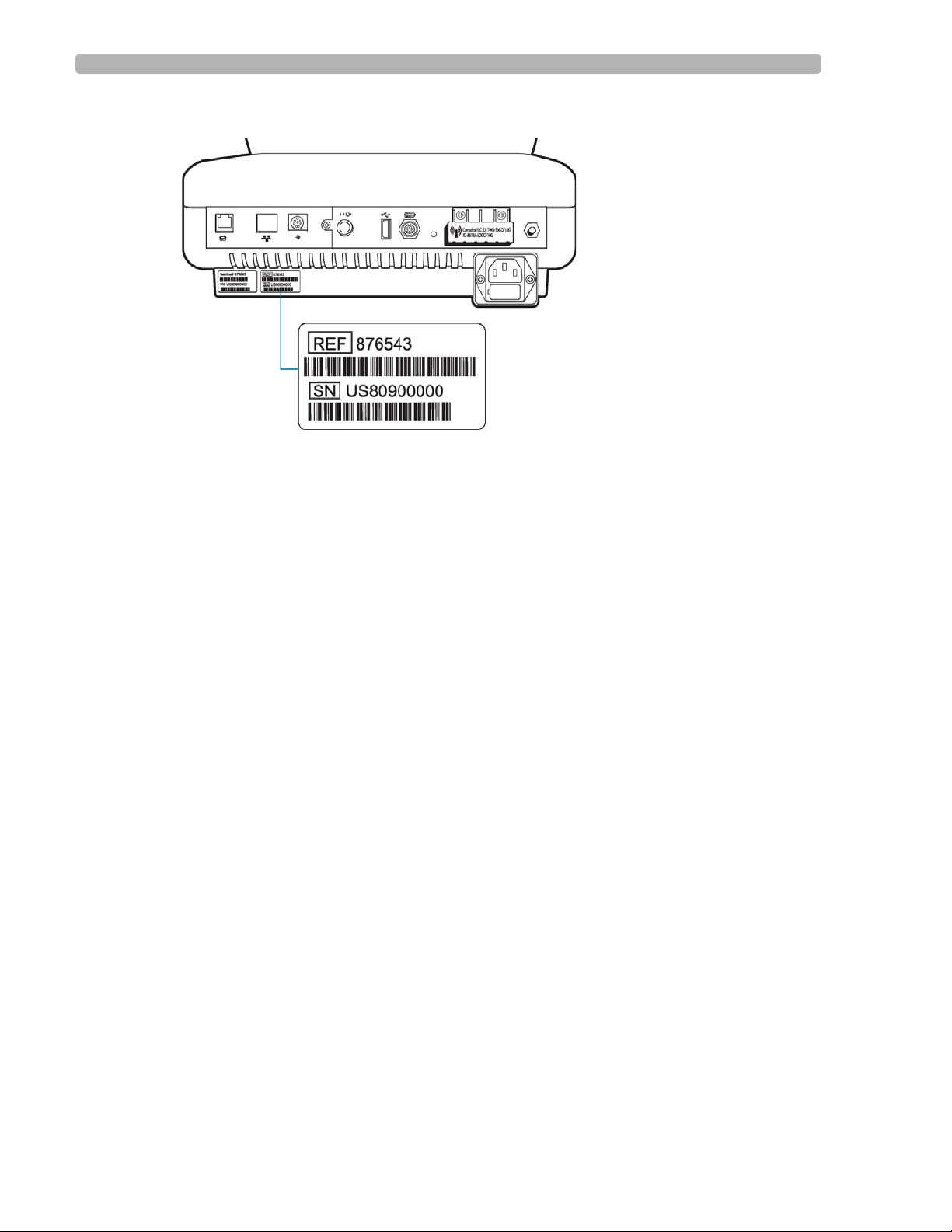
Registration for the InCenter site requires the serial number of at least one PageWriter TC
cardiograph in active use at your facility. The serial number is found on the product
identification label, located next to the text
the rear panel of the cardiograph, see (see Figure 1-1 on page 1-4).
incenter.medical.philips.com and click on the Need help? link on the main page
SN. The product identification label is located on
Software
PageWriter TC Cardiograph Service Manual 1-3
Page 12
Introduction Using the Philips InCenter Site
Figure 1-1 Cardiograph Product Identification Label (rear cardiograph view)
About Adobe Acrobat Versions
Adobe Acrobat Reader version 9.0 must be installed on the PC that is used to access the
Philips InCenter site. Previous versions of Acrobat Reader are not compatible with the Philips
InCenter site, and attempting to access InCenter with a previous version of Acrobat Reader
will result in error messages when opening documents. Uninstall all previous versions of
Acrobat Reader, and then proceed for a free install of Acrobat Reader 9.0 at:
www.adobe.com.
Any version of Adobe Acrobat Professional or Acrobat Elements are also not compatible with
the Philips InCenter site, and error messages will appear when opening documents with these
applications. Acrobat Reader 9.0 must be installed in addition to Acrobat Professional or
Acrobat Elements.
Follow this procedure when accessing documents on the Philips InCenter site.
To access documents on the Philips InCenter site:
Exit Acrobat Professional or Acrobat Elements (if open).
1
2 Start Acrobat Reader 9.0.
3 Open Internet Explorer , and go to the Philips InCenter site. Keep Acrobat Reader 9.0 open
the entire time while accessing the InCenter site.
1-4 PageWriter TC Cardiograph Service Manual
Page 13
Safety Summary Introduction
Safety Summary
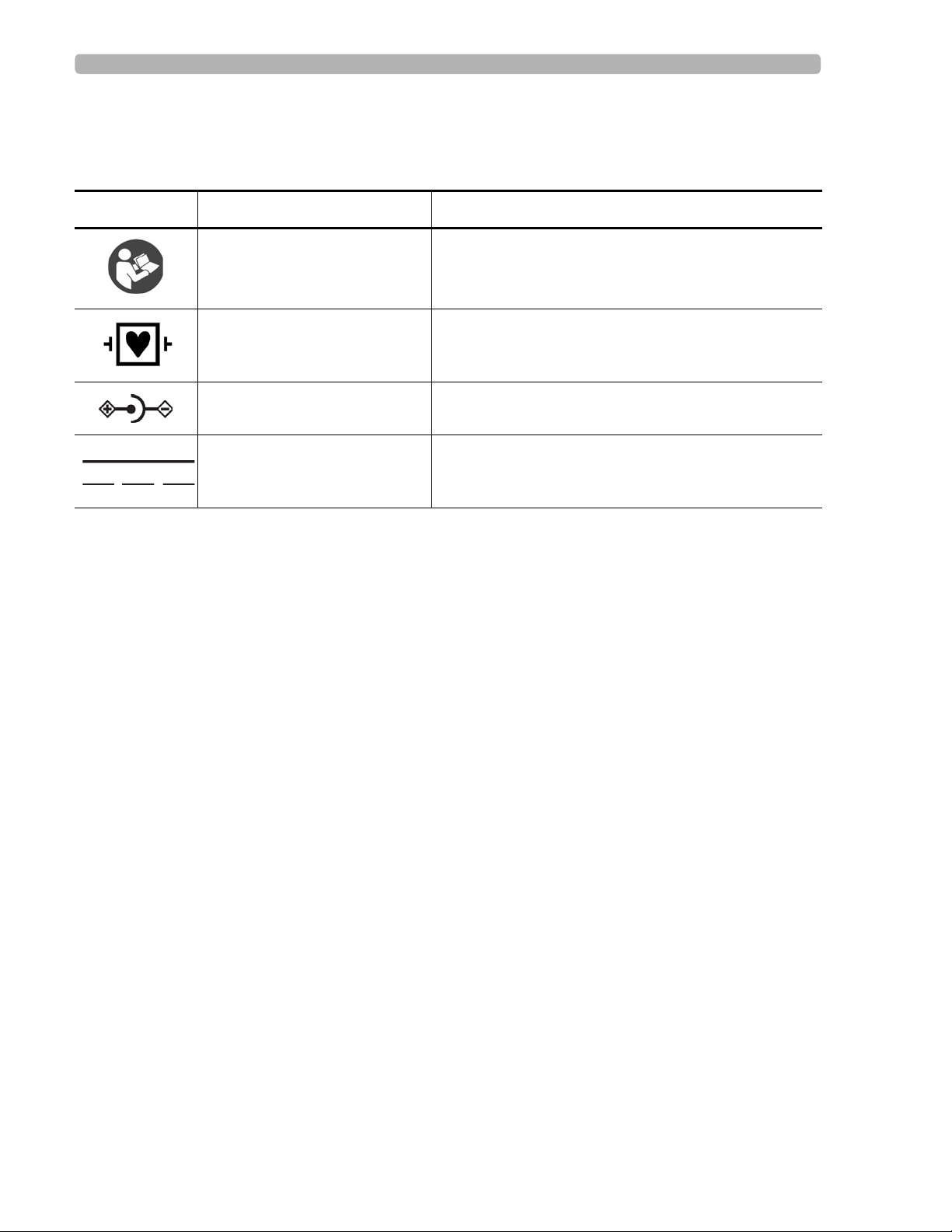
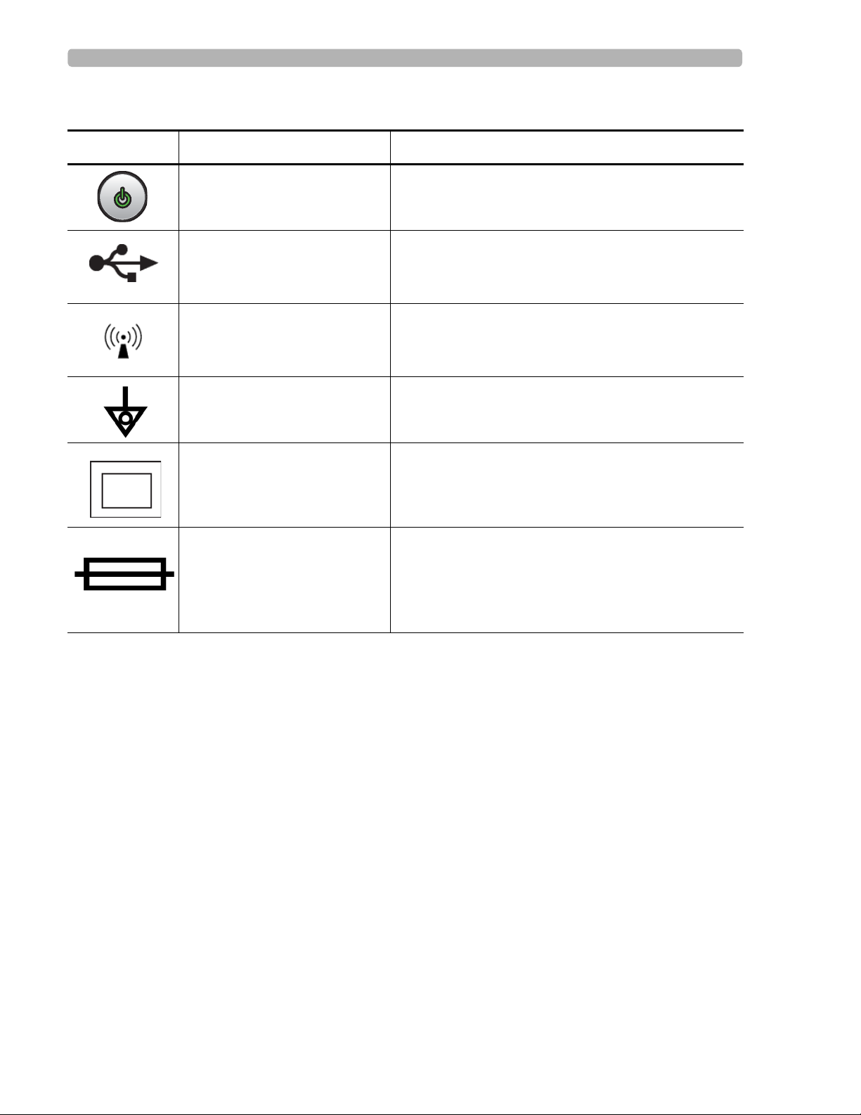
Symbols Marked on the Cardiograph or Patient Interface Module (PIM)
Symbol Name Description
Attention; read the Instructions
for Use
Type CF
Defibrillator Proof
DC Polarity Indicates the polarity of the DC power connector.
Direct Current Indicates that the equipment is suitable for direct
See the PageWriter TC Cardiograph Instructions for
Use.
ECG physio isolation is type CF, defibrillator proof.
Suitable for all patient applications including direct
cardiac application. System is in continuous operation.
current only.
PageWriter TC Cardiograph Service Manual 1-5
Page 14
Introduction Safety Summary
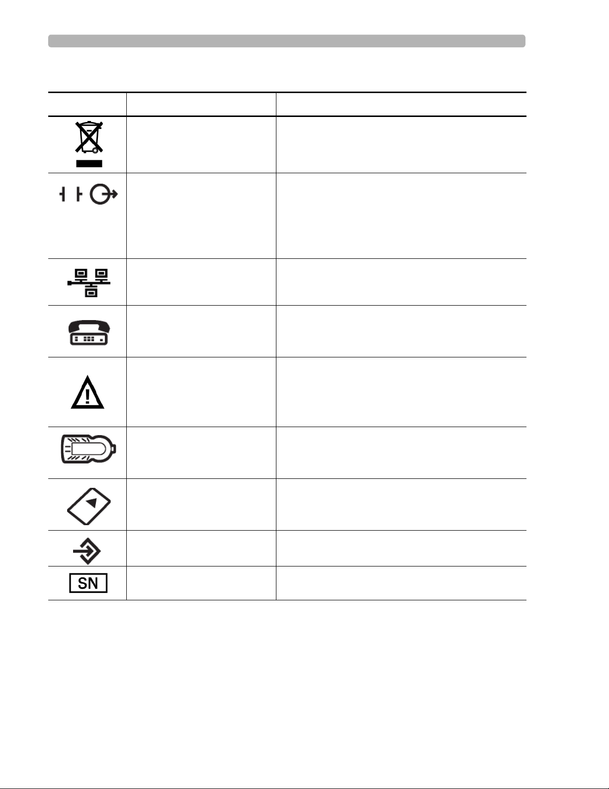
Symbols Marked on the Cardiograph or Patient Interface Module (PIM)
Symbol Name Description
Disposal Dispose of in accordance with the requirements of
your country.
ECG output signal The connector near this symbol provides access to an
analog ECG signal that can be used as a
synchronization signal for external devices, such as an
imaging device. This analog ECG signal is not
diagnostic quality and should not be used for ECG
analysis purposes.
Local Area Network (LAN)
Connector
Connect the Ethernet RJ45 LAN cable to the connector
directly above this symbol to establish LAN
connectivity.
Modem Connector Connect an analog phone line to the connector d irectly
above this symbol.
Attention; read the Instructions
for Use
Patient Interface Module (PIM)
Connector
See the PageWriter TC Cardiograph Instructions for
Use.
Connect the PIM patient data cable to the connector
located directly above this symbol.
PCMCIA icon Insert the wireless LAN card into the slot located
directly above this symbol.
PS/2 Connector Connect the Magnetic Card Reader or Barcode Reader
to the connector located directly above this symbol.
Serial Number The number next to this symbol is the serial number of
1-6 PageWriter TC Cardiograph Service Manual
the cardiograph.
Page 15
Safety Summary Introduction
Symbols Marked on the Cardiograph or Patient Interface Module (PIM)
Symbol Name Description
On/Standby Pressing the button with this symbol on it puts the
cardiograph into Standby (power saving mode).
USB Connector The connector near this symbol is used with a USB
device.
Non-ionizing electromagnetic
radiation
Interference may occur in the vicinity of equipment
marked with this symbol.
Equipotential Grounding Post Equipotential grounding post used for establishing
common ground between instruments.
Class II Protection against electric shock (PageWriter TC70
Cardiograph only).
Fuse The PageWriter TC50 Cardiograph and PageWriter
TC30 Cardiograph contains a 1.6 amp (250V) timedelay fuse.
PageWriter TC Cardiograph Service Manual 1-7
Page 16
Introduction Safety Summary
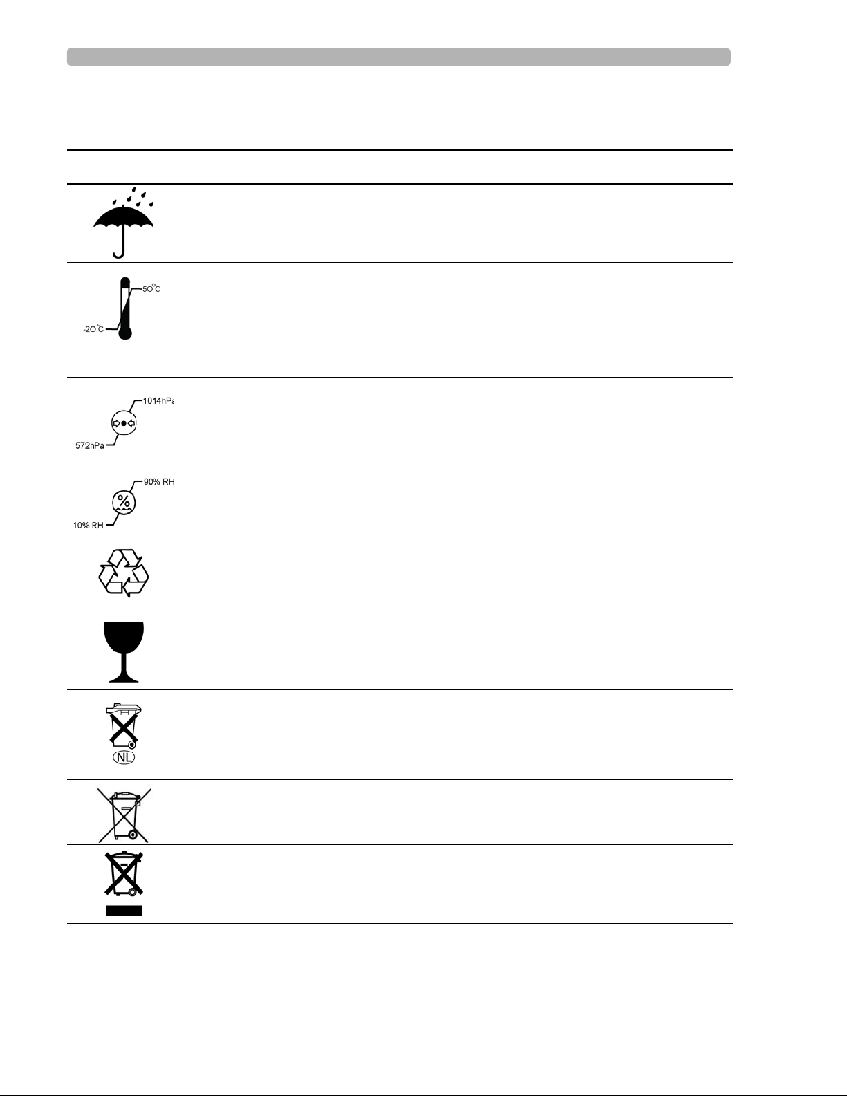
Safety Symbols Marked on the Cardiograph Packaging
Symbol Description
Keep dry.
o
Ambient temperature range of -20
transport and storage.
Note: the batteries will discharge at a rapid rate if the cardiograph is stored at a high
temperature.
Atmospheric pressure range of 0 to 4572 meters (15,000 feet), 572 hPA above sea level
for transport and storage.
C (-4o F) to 50 oC (122o F) (non-condensing) for
Relative humidity range of 10% to 90% (non-condensing) for transport and storage.
Made from recycled materials.
Fragile.
Lithium ion battery. Do not dispose of in trash. Follow local regulations for disposing of
as small chemical waste.
This product consists of devices that may contain mercury, which must be recycled or
disposed of in accordance with local, state, or federal laws. (Within this system, the
backlight lamps in the monitor display contain mercury.)
Dispose of in accordance with the requirements of your country.
1-8 PageWriter TC Cardiograph Service Manual
Page 17
Safety Summary Introduction
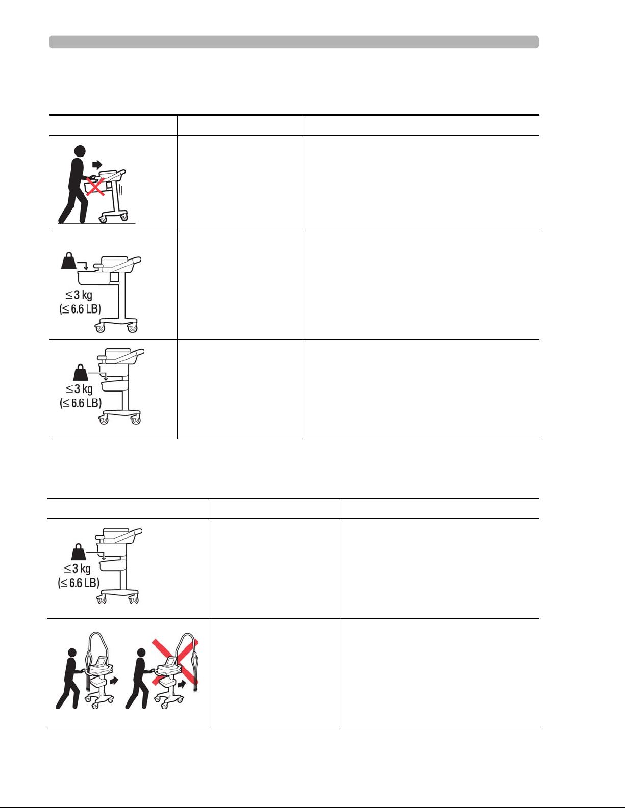
Safety and Regulatory Symbols Marked on the PageWriter TC70 Cardiograph Cart
Symbol Name Description
Cart Transport Do not transport the cart with the drawer open.
Cart Drawer Weight
Limit
Cart Storage Bin Weight
Limit
Do not place more than 3 kilograms or 6.6
pounds of weight into the cart drawer.
Do not place more than 3 kilograms or 6.6
pounds of weight into the cart storage bin.
Safety and Regulatory Symbols Marked on the PageWriter TC50/TC30 Cardiograph Cart
Symbol Name Description
Cart Storage Bin Weight
Limit
Do not place more than 3 kilograms or 6.6
pounds of weight into the cart storage bin.
Optional Patient Cable
Arm
Do not transport the cart with the patient
cable arm positioned to the side. Only
transport the cart with the patient cable
arm positioned to the front of the cart.
PageWriter TC Cardiograph Service Manual 1-9
Page 18
Introduction Safety Summary
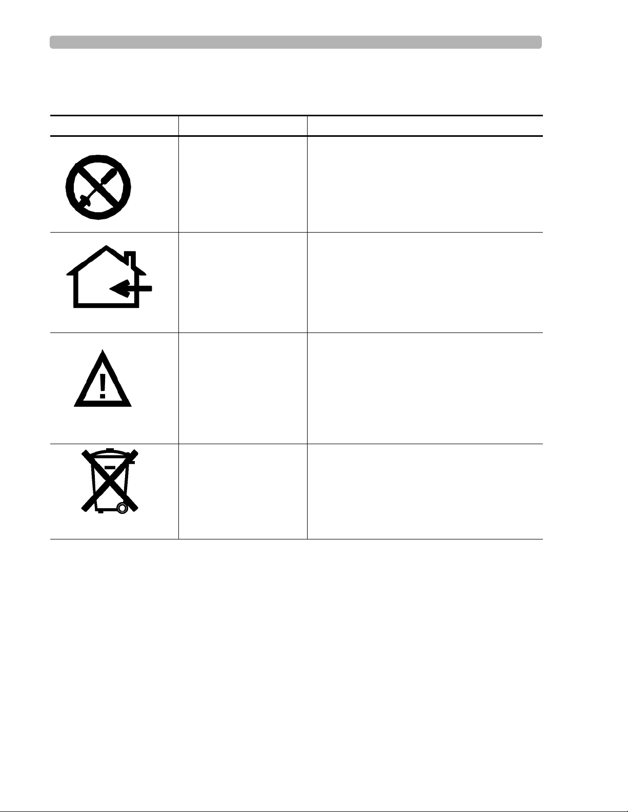
Safety and Regulatory Symbols Marked on the PageWriter TC70 Cardiograph AC Power Adapter
Symbol Name Description
No serviceable parts
inside
Indoor, dry location use
only
Attention; read the
Instructions for Use
There are no serviceable parts inside the AC
adapter. Do not open the AC adapter case.
The AC adapter is only intended for indoor use in
a dry location.
See the PageWriter TC Car diograph Instructions
for Use for information on the AC power adapter.
AC adapter disposal Dispose of in accordance with the requirements
of your country.
1-10 PageWriter TC Cardiograph Service Manual
Page 19

Important Patient and Safety Information Introduction
Important Patient and Safety Information
The PageWriter TC70 cardiograph, PageWriter TC50 cardiograph, and PageWriter TC30
cardiograph isolate all connections to the patient from electrical ground and all other
conductive circuits in the cardiograph. This reduces the possibility of hazardous currents
passing from the cardiograph through the patient’s heart to ground.
WARNING Failure to follow these warnings could affect both patient and operator safety.
Accessories and Supplies
WARNING Always clean and disinfect reusable electrodes before patient use. Failure to properly
clean and disinfect reusable electrodes before patient use may cause infectious materials
to be transferred between patients.
WARNING The Welsh bulb electrodes (available as an accessory for the cardiograph) do not meet
the requirements of IEC 60601-2-25 for defibrillation recovery time, and cannot be
reliably used for patient diagnosis immediately following defibrillation.
WARNING When using additional peripheral equipment powered from an electrical source other
than the cardiograph, the combination is considered to be a medical system. It is the
responsibility of the operator to comply with IEC 60601-1-1 and test the medical system
according to the requirements. For additional information contact Philips Medical
Systems.
WARNING Do not use non-medical peripherals within 6 feet of a patient unless the non-medical
peripherals receive power from the cardiograph or from an isolation transformer that
meets medical safety standards.
CAUTION The Welsh bulb electrodes contain natural rubber latex which may cause allergic reactions.
CAUTION The use of equipment that applies high frequency voltages to the patient (including electrosurgical
equipment and some respiration transducers) is not supported and may produce undesired results.
CAUTION Only use Philips Medical Systems replacement parts and supplies with the cardiograph. The use of non-
approved replacement parts and supplies with the cardiograph is strictly prohibited. Cardiograph
safety and performance are not guaranteed when non-approved replacement parts and supplies are
used with the cardiograph.
PageWriter TC Cardiograph Service Manual 1-11
Page 20

Introduction Important Patient and Safety Information
Using accessories, peripherals, or cables that are not supplied with the cardiograph or that
are not recommended by Philips Medical Systems can result in increased emissions or
decreased immunity of the cardiograph.
Connect other equipment in accordance with IEC 60601-1-1 Medical Electrical Systems
Standard or IEC 60601-1: 2005 (3rd Edition) Medical Electrical Equipment Standard
Clause 16 Medical Electrical Systems.
When connecting the cardiograph to other AC powered equipmen t, only connect e quipment
approved to IEC 60601-1 Medical Electrical Equipment or IEC 60950-1 Information
Technology Equipment.
Only use patient electrodes that are approved by Philips Medical Systems. The use of non-
approved patient electrodes may degrade cardiograph performance.
T o prevent burns to the pat ient, remove all ECG electrodes and lead wires prior to the use of
high frequency surgical equipment (including electrosurgical equipment and some
respiration transducers).
AC Power Adapter and AC Power Cord
WARNING Only use the external power supply with part number 453564094411 with the
PageWriter TC70 cardiograph in order to prevent electrical safety hazards. The use of
any other power supply is not approved by Philips Medical Systems.
WARNING Whenever the AC power cord is connected to a live power outlet, ensure that it is also
securely attached to the cardiograph. Always disconnect the AC power cord from the
power outlet when it is not connected to the cardiograph.
WARNING Only use grounded power cords (three-wire power cords with grounded plugs) and
grounded electrical outlets that are labeled as Hospital Only or Hospital Grade. NEVER adapt a
grounded plug to fit an ungrounded outlet by removing the ground prong. Use the
equipotential post when redundant earth ground is necessary according to IEC 60601-1-
1.
CAUTION The power supply could feel warm to the touch.
The PageWriter TC70 cardiograph external power supply, part number 453564094411, is
designed with a three wire supply system. The ground only serves a functional purpose for
EMC and not protective earth for electrical safety. Use of an appropriate three-wire power
cord is necessary to provide proper EMC operation.
1-12 PageWriter TC Cardiograph Service Manual
Page 21

Important Patient and Safety Information Introduction
Only use the AC power adapter designed to be used with the PageWriter TC70 cardiograph,
part number 453564094411 , in order to ensure continue d compliance with the requirements
of IEC 60601-1.
To disconnect the cardiograph from AC power, unplug the cardiograph AC power cord
from the mains power supply.
This equipment complies with the earth leakage current limits as specified in UL 60601-
1:2003 Medical Electrical Equipment - General Requirements for Safety, only when
connected to a 120 Volt mains power supply.
Periodically inspect the patient data cable, lead wires, and AC power cord for any worn or
cracked insulation. Ensure that no exposed wires are visible on the AC power cord.
Only use the Philips Medical Systems AC power cord (part number 453564094411)
supplied with the cardiograph. Use of any other power supply has not been verified and may
lead to operator or patient harm, including electrical shock. Periodically inspect the AC
power cord and AC power connector to ensure that both are in a safe and operable
condition. If the AC power cord or AC power connector are not in a safe or operable
condition, operate the cardiograph on battery power and contact Philips Medical Systems
for service.
Analog ECG Output Signal Port
Do not use the analog ECG output signal port (not supported on cardio graph) for diagno stic
purposes and do not use this signal for critical synchronization timing.
Do not connect any equipment to the cardiograph analog ECG output signal port that does
not meet medical safety requirements and that has not been evaluated by local safety
personnel.
Batteries
CAUTIONS Before removing and replacing batteries from the cardiograph, press down and hold the On/
Standby button ( ) (located on the front of the cardiograph), to shut down the cardiograph.
Ensure that the cardiograph is shut down. When the cardiograph is fully shut down, the screen is
black, and the On/Standby button is not illuminated. Once the cardiograph is shut down, proceed
to remove and replace the batteries.
When removing batteries from the cardiograph, the batteries could feel warm to the touch.
The battery capacity for the PageWriter TC50 cardiograph or PageWriter TC30 cardiograph
with a single battery installed using the battery with Philips part number 989803170371, is
30 minutes of continuous Rhythm printing, or 30 total ECG reports.
When operating the PageWriter TC50 cardiograph or PageWriter TC30 cardiograph with
one battery installed, only use the Philips battery with part number 989803170371. Do not
use the battery with Philips part number 989803160981 for one battery operation.
When operating the PageWriter TC70 cardiograph, PageWriter TC50 cardiograph, or
PageWriter TC30 cardiograph with two batteries installed, ensure that both batteries contain
PageWriter TC Cardiograph Service Manual 1-13
Page 22

Introduction Important Patient and Safety Information
the same Philips part number. The battery part number identification label is found on the
bottom of the battery. The cardiograph cannot operate with two batteries that contain
different part numbers. If the cardiograph is operated with two batteries with different part
numbers, the cardiograph will display an error message and will not operate.
PageWriter TC50/TC30 Cardiograph One Battery Operation
The PageWriter TC50 cardiograph, or PageWriter TC30 cardiograph with installed
software version A.04.00 and higher can operate on a single battery with Philips part
number 989803170371.
The battery capacity for the PageWriter TC50 card i ograph, or the PageWriter TC30
cardiograph with a single battery installed using the battery with Philips part number
989803170371, is 30 minutes of continuous Rhythm printing, or 30 total ECG reports.
When operating the PageWriter TC50 cardiograph, or the PageWriter TC30 cardiograph
with one battery installed, only use the Philips battery with part number 989803170371.
Do not use the battery with Philips part number 989803160981 for one battery operation.
When operating the PageWriter TC50 cardiograph or the PageWriter TC30 cardiograph
with one battery installed, the single battery may be inserted into either battery
compartment.
Cart
Ensure that the cardiograph is securely attached to the cardiograph cart before use.
Defibrillation
WARNING Do not touch the patient, patient data cable, leads, or the cardiograph during
defibrillation. Death or injury may occur from the electrical shock delivered by the
defibrillator.
Diagrams
Upon customer request, Philips Medical Systems will make available circuit diagrams,
component part lists, descriptions, calibration instructions and other technical information.
Display Accuracy
The accuracy of the ECG signals are within +/- 5% (or +/- 40 uV whichever is greater), over
a range of 0 to 5 mV, in the presence of differential and common mode DC offset voltages
of +/- 300 mV. The cardiograph performance is tested to comply with the accuracy
requirements over the dynamic ranges and frequency ranges specified in the IEC 60601-251 and AAMI EC-11 standards.
1-14 PageWriter TC Cardiograph Service Manual
Page 23

Important Patient and Safety Information Introduction
For additional details regarding accuracy and precision, refer to the Physician's Guide and
the Manufacturer's Disclosure Statement.
ECG Interpretation
CAUTION Always enter accurate patient information (including age and gender) if using the Philips DXL ECG
Algorithm or Philips 12-Lead Algorithm for ECG interpretation.
Electrodes
Philips recommends the use of disp osable elec trodes at all times for all patient applications.
Choose either adult or pediatric disposable electrodes based on the age and size of the
patient. See “Disposable and Reusable Electrodes” on page 1-49 for information on
ordering disposable electrodes.
Faxed ECGs
CAUTION No guarantee is made as to the suitability of a faxed ECG for any particular purpose, due to the
variability inherent in fax technology.
CAUTION Faxed ECGs should only be sent to secure recipient fax machines.
General Cardiograph Use
WARNING Electrical shock hazard. Keep the cardiograph, Patient Interface Module (PIM), and all
cardiograph accessories away from liquids. Do not immerse the cardiograph, PIM, or
other accessories in any liquids.
WARNING Do not use this cardiograph near flammable anesthetics. It is not intended for use in
explosive environments or in operating rooms. The disconnection or connection of AC
power, or electrostatic discharge (ESD) may result in an electrical spark.
CAUTION The cardiograph may generate electromagnetic interference (EMI) that may cause nearby equipment
to fail.
PageWriter TC Cardiograph Service Manual 1-15
Page 24

Introduction Important Patient and Safety Information
CAUTION The use of equipment that applies high frequency voltages to the patient (including electrosurgical
equipment and some respiration transducers) is not supported and may produce undesired results.
Disconnect the patient data cable from the cardiograph, or detach the leads from the patient prior to
performing any procedure that uses high frequency surgical equipment.
The use of non-Philips equipment connected to, or operating with, the PageWriter TC70
cardiograph, PageWriter TC50 cardiograph, or the PageWriter TC30 cardiograph is not
tested or supported, and may produce undesired results.
Connecting multiple cardiographs to the same patient may pose a safety hazard due to the
summation of leakage currents. Any combination of instruments should be evaluated by
local safety personnel before being put into service.
IEC 60601-2-51
For information on the standard IEC 60601-2-51, please go to the Philips InCenter web site
incenter.medical.philips.com). For information on using the Philips InCenter site, see page 1-
(
4.
Lead Wires
WARNING Electrical shock hazard. Do not touch accessible connector pins and the patient
simultaneously.
WARNING Do not touch any loose or exposed leads during defibrillation. Death or injury may occur
from the electrical shock delivered by the defibrillator.
WARNING Ensure that the electrodes or lead wires do not come in contact with any other
conductive materials (including earth-grounded materials) especially when connecting or
disconnecting electrodes to or from a patient.
Main Waveform Display Screen
Manual measurements of ECG intervals and magnitudes should be performed on printe d
ECG reports only . Do not make manual measurements of ECG intervals and magnitudes on
the main waveform display screen since these ECG representations are scaled.
1-16 PageWriter TC Cardiograph Service Manual
Page 25

Important Patient and Safety Information Introduction
Modem Card and Fax Feature
WARNING Do not connect the modem card to a phone line when the cardiograph is connected to a
patient.
WARNING Only connect the phone line to the modem connector ( ) located on the rear panel
of the cardiograph. Never attach the phone line to the LAN connector ( ).
No guarantee is made as to the suitability of a faxed ECG report for any particular purpose,
due to the variability inherent in fax technology.
Pacemaker
Pace pulses may not be visible on a printed ECG report that uses simultaneous acquisition.
Patient Data Cable
WARNING The Philips Medical Systems patient data cable (supplied with cardiograph) is an integral
part of the cardiograph safety features. Use of any other patient data cable may lead to
the distortion or corruption of patient ECG data, may compromise defibrillation
protection and degrade cardiograph performance, and overall cardiograph safety may be
seriously degraded.
WARNING Ensure that the patient data cable is securely connected to the PIM Connector ( )
on the rear panel of the cardiograph.
The PageWriter TC50 cardiograph with installed software version A.03.00 and higher is
only compatible with the Class B patient data cable (Philips part number 989803164281).
Keep the patient data cable away from power cords and any other electrical equipment.
Failure to do so can result in AC power line frequency interference on the ECG trace.
Periodically inspect the patient data cable for any cracks or breaks in the cable insulation. If
the integrity of the patient data cable is not assured, replace the patient data cable. Contact
Philips Medical Systems for further assistance, see “Contacting a Philips Response Center”
on page 5-13.
PageWriter TC Cardiograph Service Manual 1-17
Page 26

Introduction Important Patient and Safety Information
Patient Interface Module (PIM)
WARNING Always clean and disinfect the Patient Interface Module (PIM) after patient use, if the
PIM comes into direct contact with the patient’s skin. Failure to properly clean and
disinfect the PIM after direct contact with the patient’s skin may cause infectious
materials to be transferred between patients.
CAUTION If using the optional, 16-lead PIM, always ensure that the leads connected to the Patient Interface
Module (PIM) are the same leads that are displayed on the cardiograph screen.
The PageWriter TC50 cardiograph with installed software version A.03.00 and higher is
only compatible with the Class B 12-lead PIM (Philips part number 453564150741, AAMI
and 453564150761, IEC) or the Class B 16-lead PIM (Philips part number 453564150751,
AAMI and 453564150771, IEC).
Always put the cardiograph in Standby before replacing the Patient Interface Module
(PIM). Do not change the PIM while the cardiograph is in active use.
Printer
CAUTION Do not pull on the paper while an ECG report is being printed. This can cause distortion of the
waveform and can lead to potential misdiagnosis.
Servicing the Cardiograph
Only qualified personnel may service the cardiograph or may open the cardiograph housing
to access internal cardiograph components. Do not open any covers on the cardiograph.
There are no internal cardiograph components that are serviced by the operator.
The Philips Medical Systems warranty is applicable only if you use Philips Medical
Systems approved accessories and replacement parts. See “Supplies and Ordering
Information” on page 1-46 for more information.
Software
WARNING Only install Philips Medical Systems software on the cardiograph. The installation or use
of software not approved by Philips Medical Systems is strictly prohibited and
cardiograph safety and performance are not guaranteed.
1-18 PageWriter TC Cardiograph Service Manual
Page 27

PageWriter TC70 Cardiograph Components Introduction
Touch Screen
WARNING Do not use sharp objects with the touch screen or apply excessive force to the touch
screen. Applying excessive force to the touch screen may result in breaking the touch
screen display and can cause sharp, jagged parts to expel to persons nearby.
Manual measurements of ECG intervals and magnitudes should be performed on printed
ECG reports only. Do not make manual measurements of ECG intervals and magnitudes on
the touch screen display since these ECG representations are scaled.
USB Memory Stick
WARNING Do not use the USB memory stick to import ECGs from other cardiographs, or other
non-Philips devices onto any model of the PageWriter TC cardiograph.
CAUTIONS Only use the USB memory stick that is available for purchase as an optional accessory from Philips
Medical Systems with the PageWriter TC cardiograph.
Do not insert a USB memory stick into the cardiograph, or remove a USB memory stick from the
cardiograph when the cardiograph is acquiring ECG data from the patient.
Only use the USB memory stick to transfer data between the cardiograph and a computer. Do not use
the USB memory stick with other devices.
Keep all USB memory sticks that contain patient data in a secure location where they cannot be
accessed by unauthorized personnel. Always delete patient data from a USB memory stick promptly
after use.
Affix a label to all USB memory sticks that contain patient data notifying users that unauthorized
access of patient data on the USB memory stick is punishable by law.
Periodically inspect the USB connectors (side and rear of cardiograph) for any cracks or
breaks. If the integrity of a USB connector is not assured, do not use the USB connector,
and contact Philips Medical Systems for further assistance, see “Contacting a Philips
Response Center” on page 5-13.
PageWriter TC70 Cardiograph Components
The following sections include a description of all of the components of the PageWriter TC70
cardiograph, including the connection ports on the cardiograph, the Patient Interface Module
(PIM), and optional accessories available with the cardiograph. For information on ordering
any of the optional accessories for the cardiograph, see “PageWriter TC Cardiograph Supply
Part Numbers” on page 5-8.
PageWriter TC Cardiograph Service Manual 1-19
Page 28
Introduction PageWriter TC70 Cardiograph Components
A
B
DECF
G
H
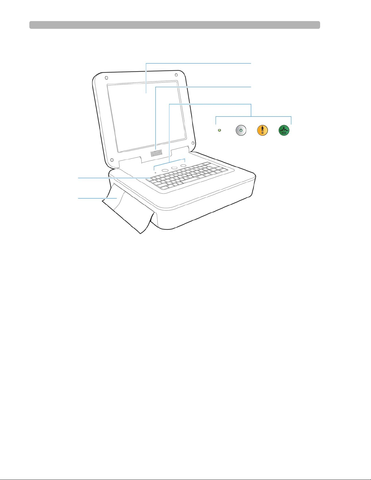
Figure 1-2 PageWriter TC70 Cardiograph (left front view)
A Touch screen F ECG button
B Audio speaker G Paper tray
C AC power on indicator light H Keyboard
D On/Standby button
E ID button
1-20 PageWriter TC Cardiograph Service Manual
Page 29
PageWriter TC70 Cardiograph Components Introduction
I
J
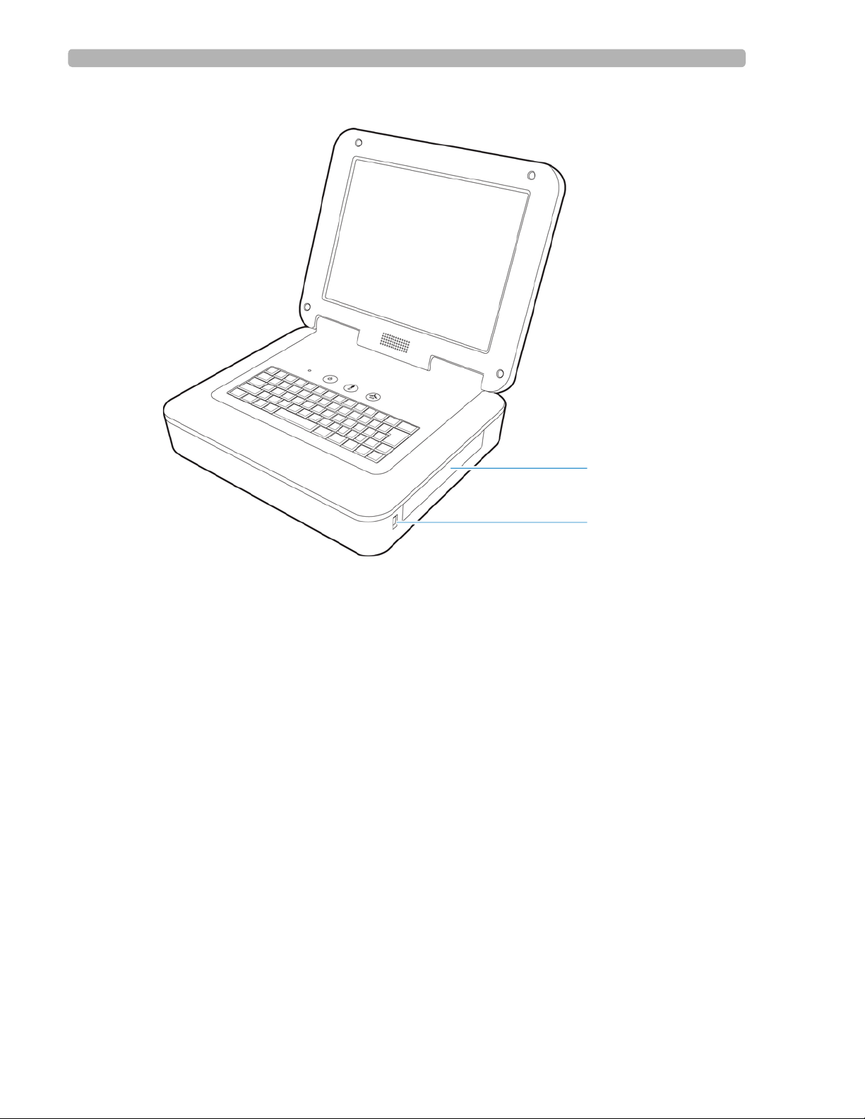
Figure 1-3 PageWriter TC70 Cardiograph (right front view)
I Battery compartment
J USB memory stick connector
PageWriter TC Cardiograph Service Manual 1-21
Page 30
Introduction PageWriter TC70 Cardiograph Components
H
D
C
B
A
E
F
G
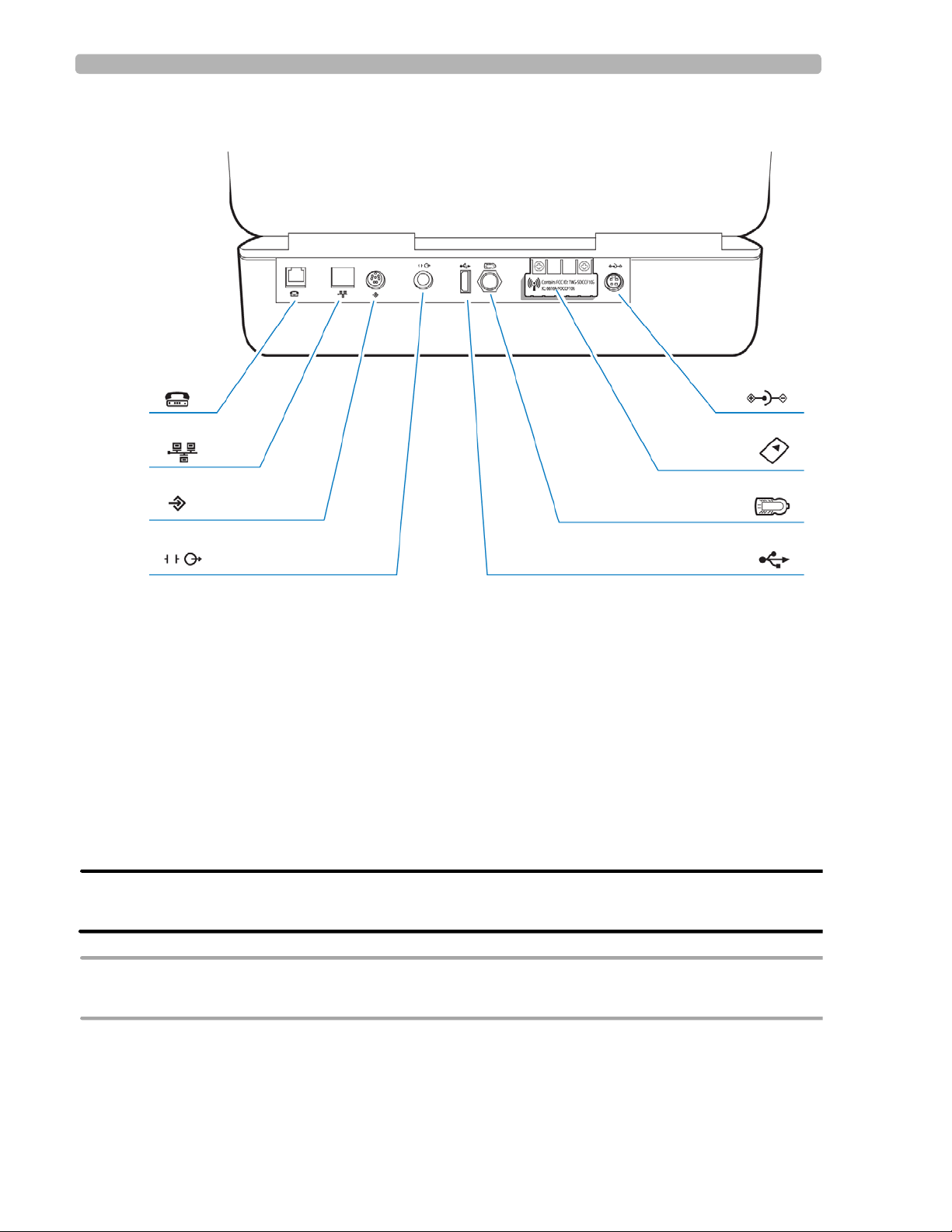
Figure 1-4 PageWriter TC70 Cardiograph (rear view)
A Modem connector G Wireless LAN card slot (with protective
cover installed)
B LAN connector H AC power connector
C Barcode reader or magnetic card reader
connector
D Analog ECG output signal connector (not
supported)
E USB connector
F PIM connector
WARNING Do not connect the modem card to a phone line when the cardiograph is connected to a
patient.
CAUTION Do not insert a USB memory stick into the cardiograph, or remove a USB memory stick from the
cardiograph when the cardiograph is acquiring ECG data from a patient.
1-22 PageWriter TC Cardiograph Service Manual
Page 31

PageWriter TC50 Cardiograph Components Introduction
A
B
D
E
C
F
GH I J
PageWriter TC50 Cardiograph Components
The following sections include a description of all of the components of the PageWriter TC50
cardiograph, including the connection ports on the cardiograph, the Patient Interface Module
(PIM), and optional accessories available with the cardiograph. For information on ordering
any of the optional accessories for the cardiograph, see “Supplies and Ordering Information”
on page 5-7.
Figure 1-5 PageWriter TC50 Cardiograph (right front view)
A Touch screen F Keyboard
B Audio speakers G AC power on indicator light
C Battery compartment H On/Standby button
D USB memory stick connector I ID button
E Paper tray J ECG button
PageWriter TC Cardiograph Service Manual 1-23
Page 32

Introduction PageWriter TC50 Cardiograph Components
H
D
C
B
A
E
F
G
I
Figure 1-6 PageWriter TC50 Cardiograph (rear view)
A Wireless LAN card slot (with protective cover
installed)
G Barcode reader or magnetic card reader
connector
B Equipotential grounding post H LAN connector
C AC power cord connector I Modem connector
D PIM connector
E USB connector
F Analog ECG output signal connector (not
supported)
WARNING Do not connect the modem card to a phone line when the cardiograph is connected to a
patient.
CAUTIONS Do not insert a USB memory stick into the cardiograph, or remove a USB memory stick from the
cardiograph when the cardiograph is acquiring ECG data from a patient.
Only use grounded power cords (three-wire power cords with grounded plugs) and grounded
electrical outlets that are labelled as Hospital Only or Hospital Grade. Never adapt a grounded plug to
fit an ungrounded outlet by removing the ground prong. Use the equipotential post when redundant
earth ground is necessary according to IEC 60601-1-1.
1-24 PageWriter TC Cardiograph Service Manual
Page 33

PageWriter TC30 Cardiograph Components Introduction
A
B
D
E
C
F
GH I J
PageWriter TC30 Cardiograph Components
The following sections include a description of all of the components of the PageWriter TC30
cardiograph, including the connection ports on the cardiograph, the Patient Interface Module
(PIM), and optional accessories available with the cardiograph. For information on ordering
any of the optional accessories for the cardiograph, see “Supplies and Ordering Information”
on page 5-7.
Figure 1-7 PageWriter TC30 Cardiograph (right front view)
A Touch screen F Keyboard
B Audio speakers G AC power on indicator light
C Battery compartment H On/Standby button
D USB memory stick connector I ID button
E Paper tray J ECG button
PageWriter TC Cardiograph Service Manual 1-25
Page 34

Introduction PageWriter TC30 Cardiograph Components
H
D
C
B
A
E
F
G
I
Figure 1-8 PageWriter TC30 Cardiograph (rear view)
A Wireless LAN card slot (with protective cover
installed)
G Barcode reader or magnetic card reader
connector
B Equipotential grounding post H LAN connector
C AC power cord connector I Modem connector
D PIM connector
E USB connector
F Analog ECG output signal connector (not
supported)
WARNING Do not connect the modem card to a phone line when the cardiograph is connected to a
patient.
CAUTIONS Do not insert a USB memory stick into the cardiograph, or remove a USB memory stick from the
cardiograph when the cardiograph is acquiring ECG data from a patient.
Only use grounded power cords (three-wire power cords with grounded plugs) and grounded
electrical outlets that are labelled as Hospital Only or Hospital Grade. Never adapt a grounded plug to
fit an ungrounded outlet by removing the ground prong. Use the equipotential post when redundant
earth ground is necessary according to IEC 60601-1-1.
1-26 PageWriter TC Cardiograph Service Manual
Page 35

Patient Interface Module (PIM) Introduction
Patient Interface Module (PIM)
The same Patient Interface Module (PIM) is used on all models of the PageWriter TC
cardiograph. The PIM is a hand-held device that connects to the patient data cable. The PIM is
available in a standard 12-lead, or for the PageWriter TC70 and TC50 cardiographs, an
optional 16-lead model is available. For information on configuring the optional 16-lead PIM,
see “Configuring the 16-Lead PIM (PageWriter TC70 and PageWriter TC50 cardiograph
only)” on page 1-31.
NOTE Figure 1-9 shows AAMI version PIMs.
Figure 1-9 16-lead (left) and 12-lead (right) Patient Interface Module (PIM)
About Class A and Class B Patient Data Cables and PIMs
Prior to August, 2009, PageWriter TC70 cardiographs with installed software version A.02.00
and lower were shipped from Philips Medical Systems with Class A patient data cables and
Class A PIMs. All PageWriter TC70 cardiographs and PageWriter TC50 cardiographs with
installed software version A.03.00 and higher are shipped from Philips Medical Systems with
Class B patient data cables and Class B PIMs.
The only visual difference between a Class A and a Class B PIM or patient data cable is the
number of connectors on the PIM, and the number of pins on the PIM connector end of the
patient data cable. All Class A devices have 5 connectors/pins on the PIM connector, and on
the PIM connector end of the patient data cable. All Class B devices have 8 connectors/pins on
the PIM connector, and on the PIM connector end of the patient data cable.
NOTE Both Class A and Class B patient data cables have 5 pins on the connector end that attaches to the
cardiograph.
Class A patient data cables can only be used with a Class A PIM on the PageWriter TC70
cardiograph. Class B patient data cables can only be used with a Class B PIM on any model of
the PageWriter TC cardiograph. When ordering replacement patient data cables or PIMs from
PageWriter TC Cardiograph Service Manual 1-27
Page 36

Introduction Patient Interface Module (PIM)
AB
AB
Philips Medical Systems, check the number of connectors on the PIM, and also check the
number of pins on the PIM connector end of the patient data cable to ensure that you are
ordering the correct Class A or Class B device.
NOTE If you are unable to connect a patient data cable to a PIM connector, check that both devices are
compatible. You cannot connect a Class A patient data cable to a Class B PIM.
Figure 1-10 Class A and Class B Patient Data Cable Connectors
A Class A patient data cable (5 pins) B Class B patient data cable (8 pins)
Figure 1-11 Class A and Class B Patient Interface Module (PIM) Connectors
A Class A PIM (5 connectors) B Class B PIM (8 connectors)
Attaching the Patient Data Cable to the PIM and Cardiograph
The patient data cable must be attached to the PIM connector before use. Once attached to the
PIM, the patient data cable is then attached to the cardiograph through the appropriate PIM
connector on the rear of the cardiograph.
WARNING Ensure that the patient data cable is securely connected to the PIM connector ( )
on the rear panel of the cardiograph.
1-28 PageWriter TC Cardiograph Service Manual
Page 37

Patient Interface Module (PIM) Introduction
WARNING The Philips Medical Systems patient data cable (supplied with cardiograph) is an integral
part of the cardiograph safety features. Use of any other patient data cable may lead to
the distortion or corruption of patient ECG data, may compromise defibrillation
protection and degrade cardiograph performance, and overall cardiograph safety may be
seriously degraded.
NOTE The PageWriter TC50 cardiograph and the PageWriter TC30 cardiograph with installed software
version A.03.00 and higher are only compatible with the Class B patient data cable (Philips part
number 989803164281).
To attach the patient data cable to the PIM and to the cardiograph:
1
Align the raised dot on the top of the patient data cable connector with the front of the
PIM. Insert the patient data cable connector through the metal housing. Push the patient
data cable connector firmly into the PIM connector . The connector clicks when it is locked
into position.
2 Connect the other end of the patient data cable to the PIM connector port ( ) located
on the rear panel of the cardiograph. Align the raised circle on the cable connector upright
as shown in the figure. Turn the cable connector to the right to lock it into position.
PageWriter TC Cardiograph Service Manual 1-29
Page 38

Introduction Patient Interface Module (PIM)
3 Drape the patient data cable over the top of the rear handle on the cart to help ensure that
the patient data cable does not drag on the ground.
To disconnect the patient data cable from the PIM:
Twist the end of the patient cable connector inside the metal housing and pull the
connector out.
Special Note about Patient Interface Module (PIM)
The PIM is an electronic device and can feel warm if placed on bare skin.
CAUTION If the PIM is placed on the patient’s bare skin, always place a sheet or cloth between the PIM and the
patient. If the PIM is left on the patient’s skin for an extended period of time, the PIM could reach a
maximum temperature of 46 °C (114.8 °F) in a room environment with a temperature of 40 °C (104
°F).
1-30 PageWriter TC Cardiograph Service Manual
Page 39

Patient Interface Module (PIM) Introduction
A
A
Figure 1-12 Placing PIM on patient’s skin
A Cloth placed between PIM and patient
PIM ECG Button
The PIM has an ECG button that is used to take ECGs from the bedside.
Figure 1-13 ECG button on PIM
A PIM ECG button
Configuring the 16-Lead PIM (PageWriter TC70 and PageWriter TC50 cardiograph only)
The optional 16-lead PIM may be configured to support up to 16 optional leads for adult and
pediatric application. The 16-lead PIM is shipped with four optional leads, color clip
identifiers, and shorting plugs. For information on ordering the 16-lead PIM option, see
“Supplies and Ordering Information” on page 5-7.
NOTE The 16-lead PIM is not available with the PageWriter TC30 cardiograph.
PageWriter TC Cardiograph Service Manual 1-31
Page 40

Introduction Patient Interface Module (PIM)
A
B
C
D
CAUTION When using the 16-lead PIM, always ensure that the leads connected to the Patient Interface Module
(PIM) are the same leads that are displayed on the cardiograph screen.
Figure 1-14 16-Lead PIM Kit
A Color identification clips C Lead separator
B Optional leads (4 total) D Shorting plug (6 total)
To configure the 16-lead PIM:
1
Press the On/Standby button ( ) to put the cardiograph into Standby.
CAUTION Always put the cardiograph in Standby before connecting or disconnecting the Patient Interface
Module (PIM). Do not disconnect or connect the PIM to the cardiograph while the cardiograph is
in active use.
2 Disconnect the PIM from the cardiograph, if necessary.
3 There are six optional lead connectors available on the PIM. These optional lead
connectors are labeled:
C3R/V3R, C4R/V4R, C5R/V5R, C7/V7, C8/V8 and C9/V9. Any of
these optional leads (up to a maximum of four) may be configured for use with the
cardiograph.
NOTE The cardiograph does not support the configuration of 18 leads. Any of the optional leads, up to a
maximum of 4, may be configured for use with the cardiograph.
1-32 PageWriter TC Cardiograph Service Manual
Page 41

Patient Interface Module (PIM) Introduction
A
Figure 1-15 16-Lead PIM Optional Lead Connectors (AAMI/IEC)
A Optional lead connectors
Attach the appropriate color-coded identification clip (included in the lead kit) to the lead,
4
and attach the small color clip near the connector end of the lead wire.
Figure 1-16 Attaching the color clips to the lead
PageWriter TC Cardiograph Service Manual 1-33
Page 42

Introduction Patient Interface Module (PIM)
5 Attach the lead to the correct lead connector on the PIM. If any lead connectors on the
PIM are left empty, insert a shorting plug (included in kit).
Figure 1-17 Shorting Plug (included in Lead Kit)
NOTE To configure the 16-lead PIM for standard 12 leads, insert shorting plugs into all of the optional
lead connectors.
6
Ensure that each lead is firmly connected to the PIM.
Recommended 16-Lead Configurations
Table 1-1 provides some suggested configurations of the 16-lead Patient Interface Module
(PIM) for adult and pediatric application.
NOTE The recommended 16-lead configuration options described in Table 1-1 are the only 16-lead options
that are compatible with the TraceMaster ECG Management System.
Table 1-1 15 and 16-Lead PIM Configuration Options
Lead Option Standard 12-leads plus extended
leads (AAMI/IEC)
Pediatric
V3R/C3R, V4R/C4R, V7/C7
(15 leads)
Posterior
V7/C7, V8/C8, V9/C9
(15 leads)
Lead Placement
1-34 PageWriter TC Cardiograph Service Manual
Page 43

Installing the Batteries Introduction
Table 1-1 15 and 16-Lead PIM Configuration Options (continued)
Lead Option Standard 12-leads plus extended
leads (AAMI/IEC)
Balanced
V3R/C3R, V4R/C4R, V7/C7, V8/C8
(16 leads)
Installing the Batteries
The PageWriter TC70 cardiograph is shipped with two batteries, and the PageWriter TC50
and PageWriter TC30 cardiographs are shipped with one or an optional two batteries that are
used to power the cardiograph when AC power is not available.
Lead Placement
CAUTION Insert the batteries into the cardiograph before plugging the cardiograph into AC power.
Notes about Battery Installation
NOTES If operating the PageWriter TC50 or PageWriter TC30 cardiograph with one battery installed, the
battery may be inserted into either battery compartment.
When operating the PageWriter TC50 or PageWriter TC30 cardiograph with one battery installed,
only use the Philips battery with part number 989803170371. Do not use the battery with Philips
part number 989803160981 for one battery operation.
When operating any model of the PageWriter TC cardiograph with two batteries installed, ensure
that both batteries contain the same Philips part number. The battery part number identification
label is found on the bottom of the battery. The cardiograph cannot operate with two batteries that
contain different part numbers. If the cardiograph is operated with two batteries with different part
numbers, the cardiograph will display an error message and will not operate.
PageWriter TC Cardiograph Service Manual 1-35
Page 44

Introduction Installing the Batteries
To install the batteries:
1
Open the battery door.
2 Locate the two gold pull tabs inside of the battery compartment. Pull the tabs straight out
of the battery compartment and lay flat.
1-36 PageWriter TC Cardiograph Service Manual
Page 45

Installing the Batteries Introduction
3 Insert the battery with the external connector facing the bottom rear of the compartment.
NOTE If operating the PageWriter TC50 or the PageWriter TC30 cardiograph with a single battery
installed, the battery may be inserted into either battery compartment.
4
Push in the battery and ensure that the battery is fully inserted into the slot. The pull tab
will insert along with the battery . If necessary , insert the second battery following the same
procedure.
PageWriter TC Cardiograph Service Manual 1-37
Page 46

Introduction Installing the Batteries
5 Reinstall the battery door.
6 Connect the AC power cord to the cardiograph. Charge the batteries for five hours before
operating the cardiograph on battery power only.
Charging the Batteries
Charge the batteries for five hours prior to initial use. Plug the cardiograph into AC power
whenever possible, and fully charge the batteries. Proper battery maintenance and care,
including frequent and full charging of the batteries, will help to prolong battery life.
There are configurable power saving features available on the cardiograph. These features are
used to help prolong overall battery life, and to optimize battery power use between battery
charges.
1-38 PageWriter TC Cardiograph Service Manual
Page 47

Installing the Batteries Introduction
A
CAUTION When removing the batteries from the cardiograph, the batteries could feel warm to the touch.
Calibrating the Batteries
The batteries may require periodic calibration to ensure the continued accuracy of the battery
power and overall battery status information displayed on the cardiograph. When battery
calibration is required, a message appears on the Battery Status window, see Figure 1-19 on
page 1-41. For more information on battery calibration, see “Battery Calibration” on
page 3-12.
Battery Power Indicator
The battery power indicator ( ) appears on the Status Bar and is always visible. The
indicator displays the current battery power level. After installing and initially charging the
batteries for five hours, the cardiograph can operate on AC power while the batteries are
charging, but the batteries will charge at a slower rate.
Figure 1-18 Battery Power Indicator on the Status Bar
A Battery level indicator
PageWriter TC Cardiograph Service Manual 1-39
Page 48

Introduction Installing the Batteries
To check the battery power level:
1
From any screen, tap on the battery icon on the Status Bar ( ). The Battery Status
window appears. This window provides detailed information on the status of the
cardiograph batteries. The battery icon indicates the overall charge status of the battery.
Table 1-2 Battery Icon (on Status Bar or Battery Status window)
Icon on Status Bar Battery Level
Fully Charged Battery
75% power capacity
50% power capacity
Low Battery Power:
red battery icon appears when power level is below
25%
cardiograph beeps and an error message appears until
the unit is plugged into AC power (audio feature may
be disabled)
tap the icon to see how many minutes are left of
operating battery power
If overall battery power is below 15% and the
cardiograph is in Standby, when the On/Standby button
( ) is pressed it will flash green five times and the
cardiograph will be unable to return to active use. Plug
the cardiograph into AC power to recharge the
batteries.
1-40 PageWriter TC Cardiograph Service Manual
No or Dead Battery
Page 49

Using the On/Standby Button Introduction
NOTE If the Plug in the Cardiograph message appears, the cardiograph needs to be plugged into AC
power immediately.
Figure 1-19 Battery Status Information with Plug in the Cardiograph message
2
Touch the Close button to close the window.
Using the On/Standby Button
The On/Standby button ( ) is used to:
put the cardiograph into Standby when not in active use in order to conserve battery power
shut down all power to the cardiograph for extended periods of inactivity
return the cardiograph to active use
CAUTION Ensure that all patient data from an active patient session is saved before entering Standby, or
shutting down the cardiograph. Unsaved patient data (patient identification information,
unreviewed Event Markers, unsaved ECGs) are deleted when the cardiograph enters Standby.
To put the cardiograph into Standby (power save):
Press the On/Standby button gently to put the cardiograph into Standby. When the
1
cardiograph is in Standby, the screen is black.
TIP Plug the cardiograph into AC power whenever possible to recharge the batteries.
2
Press the On/Standby button again to return the cardiograph to active use. The previously
viewed screen (prior to entering Standby) appears.
PageWriter TC Cardiograph Service Manual 1-41
Page 50

Introduction Using the Wireless LAN Card
NOTES If overall battery power is below 15% and the cardiograph is in Standby, when the On/Standby
button is pressed it will flash green five times and the cardiograph will be unable to return to
active use. Plug the cardiograph into AC power to recharge the batteries.
If the Disclose or Rhythm screens are viewed prior to entering Standby, the Main screen will
appear when the cardiograph is returned to active use.
To shut down the cardiograph:
1
Press and hold the On/Standby button for 3 seconds to shut down the cardiograph. When
the cardiograph is shut down, any unsaved patient data is lost.
2 Press the On/Standby button to return the cardiograph to active use. The cardiograph fully
restarts and the Main screen appears.
Using the Wireless LAN Card
The PageWriter TC cardiograph supports wireless connectivity which is used to transfer ECG
and order data between the cardiograph and a TraceMaster ECG Management System. The
cardiograph can also be configured to transfer ECG data using a wireless connection to a third
party ECG management system. For information on configuring cardiograph connectivity
with a TraceMaster or other third party ECG management system, see the PageWr iter TC
Cardiograph Network Configuration Guide available on the User Documentation and
Training DVD, or the file can be downloaded from the Philips InCenter site.
CAUTION Only use wireless LAN cards with the PageWriter TC cardiograph that have been purchased from
Philips Medical Systems. The use of non-approved wireless LAN cards with either model cardiograph
is not tested or supported, and Philips Medical Systems does not guarantee cardiograph operation or
wireless LAN connectivity.
For information on installing the card and configuring the cardiograph for wireless
transmission, see the PageWriter TC Cardiograph Wireless LAN Installation Instructions. The
file is available for download from the Philips InCenter site (
incenter.medical.philips.com).
For information on ordering the wireless card, see “Supplies and Ordering Information” on
page 5-7.
1-42 PageWriter TC Cardiograph Service Manual
Page 51

Using the Modem Card Introduction
Using the Modem Card
The modem card is an optional accessory that is used to fax ECGs to a configured receiving
fax machine, or is used to transfer ECGs or orders by modem between the cardiograph and a
TraceMaster ECG Management System. The cardiograph can also be configured to transfer
ECG data by modem to a third party ECG management system. For information on
configuring cardiograph connectivity with a TraceMaster or other third party ECG
management system, see the PageWriter TC Cardiograph Network Configuration Guide
available on the User Documentation and Training DVD, or the file can be downloaded from
the Philips InCenter site.
For information on ordering the modem card, see “Supplies and Ordering Information” on
page 5-7.
WARNING Do not connect the modem card to a phone line when the cardiograph is connected to a
patient.
Using the USB Memory Stick
The USB memory stick is an optional accessory that is used to transfer orders to the
cardiograph from a computer that has the WebSelect Utility installed, and can also be used to
transfer completed ECGs (as either an XML or as a PDF file) from the cardiograph to a
TraceMaster ECG Management System, remote networked PC or server, or other third party
ECG management system. The USB memory stick can also be used to save custom settings
specified on the Setup screens as a Custom Settings file. This Custom Settings file can then be
transferred to additional cardiographs to help speed up the configuration process.
For information on using the WebSelect Utility, see the Using OrderVue with PageWriter
Cardiographs guide. This guide is available for download from the Philips InCenter site. For
information on the Philips InCenter site, See "Using the Philips InCenter Site" on page 1-3
CAUTION The PageWriter TC cardiographs only support the USB memory stick that is available for purchase as
an optional accessory from Philips Medical Systems. Philips does not guarantee that other USB
memory sticks are compatible with the PageWriter TC cardiographs.
PageWriter TC Cardiograph Service Manual 1-43
Page 52

Introduction Using the Barcode Reader
A
Figure 1-20 USB memory stick inserted into USB connector
A USB memory stick inserted into USB connector (tip illuminates when properly inserted)
The USB memory stick can store up to 200 ECGs and 200 orders. Ensure that the USB
memory stick is firmly inserted into the USB connector located on the front right side of the
cardiograph (next to the battery door). The tip of the USB memory stick illuminates when it is
properly inserted into the USB connector.
CAUTION Do not insert a USB memory stick into the cardiograph, or remove a USB memory stick from the
cardiograph when the cardiograph is acquiring ECG data from a patient.
CAUTION Only use the USB memory stick to transfer data between a PageWriter TC cardiograph and a
computer. Do not use the memory stick with other devices.
Using the Barcode Reader
The barcode reader is an optional accessory that is used to quickly enter ID information by
scanning a barcode.
The barcode reader attaches to the barcode reader connector ( ) on the rear panel of the
cardiograph. Attach the barcode reader to the cardiograph before turning on AC power. For
information on ordering the barcode reader, see “Supplies and Ordering Information” on
page 5-7.
NOTE The Metrologic Scanner Instructions for Use (only available in English), which provides complete
information on configuring and using the barcode scanner, is included on the User Documentation and
Training DVD, or is available for download from the Philips InCenter site.
1-44 PageWriter TC Cardiograph Service Manual
Page 53

Using the Cardiograph Touch Screen Introduction
Figure 1-21 The Barcode Reader
Using the Cardiograph Touch Screen
The touch screen provides access to all of the cardiograph features. Simply touch the buttons
on the screen to open the different screens and to perform different functions.
PageWriter TC Cardiograph Service Manual 1-45
Page 54

Introduction Using the Cardiograph Touch Screen
J
A B C
D
E
F
G
H
I
K
Touch Screen Overview
The touch screen is organized into different areas that are grouped by function. The following
sections provide an overview of each area of the touch screen.
Figure 1-22 Touch Screen Overview
Table 1-1 Touch Screen Overview
Touch Screen Item Feature Description
A
Selected Exam Type
The Exam Type selected for the current patient
session.
The available Exam Types are: Resting 12-
Lead
TC70/TC50 only), and
Touch the button to change the selected Exam
Type.
1-46 PageWriter TC Cardiograph Service Manual
, Resting Extended Lead (PageWriter
Timed ECG.
Page 55

Using the Cardiograph Touch Screen Introduction
Table 1-1 Touch Screen Overview (continued)
Touch Screen Item Feature Description
B
C
D
Exam Layout
Current Operating
Settings
Status Bar
The settings underneath this button include the
selected ECG report layout settings, and the
level of interpretation generated by the Philips
algorithm that are being applied to the selected
Exam Type.
Any of the settings on this screen may be
edited, and the new settings are applied to the
current patient session.
The settings underneath this button include the
selected filters (Artifact, Baseline Wander),
pacing detection setting, and report scaling
settings being applied to the current patient
session.
The Unknown pacing setting is recommended
for most ECGs.
Displays information about the current
cardiograph settings, including selected Exam
Type, current patient name, network
connectivity status, PIM status, and the current
date and time.
E
F
G
H
Waveform Display
Toolbar
Help
Setup
See "The Status Bar" on page 1-51.
Display area for ECG waveforms. Lead
connection quality is indicated by the color of
the waveform.
Press the up arrow ( ) or the down arrow
( ) key (on keyboard) to change the
displayed lead format.
All cardiograph ECG acquisition modes and ECG
management features.
Provides information on how to use the
cardiograph.
The settings underneath this button are used to
configure or change cardiograph settings, or to
access the service utilities. Access to these screens
may require entering a password.
PageWriter TC Cardiograph Service Manual 1-47
Page 56

Introduction Using the Cardiograph Touch Screen
Table 1-1 Touch Screen Overview (continued)
Touch Screen Item Feature Description
I
ECG Storage and
Management Features
Provides access to the ECG Archive, which is
used as temporary storage for all ECGs
acquired on the cardiograph.
From the Archive, ECGs may be transferred (as
an XML file or as a PDF file) to a TraceMaster
ECG Management System, a third party ECG
management system, a USB memory stick, or
as a PDF file only to a configured networked
remote PC or server.
From the Archive, a TraceMaster server may
be searched for previous ECGs to view and
print on the cardiograph.
The number on the button (9) displays the
number of ECGs currently stored in the
Archive.
J
Rhythm and Disclose
Features
The Rhythm feature is used to print continuous
rhythm strips until the
The Disclose feature is used to review captured
Stop button is touched.
Events, to view continuous data from one
selected lead, or to print ECG reports in a
variety of formats.
K
1-2-3 Operation
Features
1-48 PageWriter TC Cardiograph Service Manual
The number on the Disclose button (0) displays
the number of Events currently stored in
Disclose.
The Map, ID, and ECG buttons are used in
sequence to acquire and print an ECG.
Page 57

Using the Cardiograph Touch Screen Introduction
Changing the Lead Format on the Main ECG Screen
The format of the waveforms that display on the Main screen can be changed at any time. The
available lead formats are described in Table 1-3.
Table 1-3 Main Screen Lead Formats
Lead Format Description
12x1 or 16x1
6x2 (12-lead option) or
Split Screen View (16-lead
option)
3x4
This view provides ten seconds of continuous ECG
waveform data for each available lead
The 16x1 format is only available with the PageWriter
TC70 cardiograph with the 16-lead option
The PageWriter TC50 cardiograph with the 16-lead
option will only display the 12x1 view; to view all 16
leads select the split screen view (see below)
This view provides five seconds of continuous ECG
waveform data for each lead on a split screen
In the split screen display, the limb and augmented
leads are on the left, and the precordial leads are on
the right for both the 12-lead and the 16-lead display
option
For the TC30 cardiograph only , this is the default lead
format on the cardiograph, see (see Figure 1-23 on
page 1-50)
This view provides 2.5 seconds of waveform data for
each lead, with 3 total rows with 4 leads in each row
In this view, the limb and augmented leads are on the
left, and the precordial leads are on the right
In this view , only 12 leads are displayed even if the
16-lead option is being used
PageWriter TC Cardiograph Service Manual 1-49
Page 58

Introduction Using the Cardiograph Touch Screen
B
A
Figure 1-23 Main Screen with Split Screen View (12 Leads Displayed)
A Limb Leads B Precordial Leads
To change the lead display on the main screen:
Press the down arrow key (on keyboard) or the up arrow key to scroll through the
1
available Main screen lead formats.
2 Press the up arrow key (on keyboard) to change the display back to the original view.
3 For the TC30 cardiograph only, the lead format that displays on the Main screen when the
cardiograph is shut down (by pressing and holding the On/Standby button ( ) will be
retained once the cardiograph is returned to active use.
1-50 PageWriter TC Cardiograph Service Manual
Page 59

Using the Cardiograph Touch Screen Introduction
ABC DEFGH
I
J
K
The Status Bar
The Status Bar (top of the screen) provides information about the current cardiograph settings.
The Status Bar is always visible.
Figure 1-24 The Status Bar
Table 1-4 The Status Bar
Status Bar Item Feature Description
A
B
C
D
Selected Exam Type
ECG Layout
Operating Settings
Event Marker Alert
The Exam T ype selected for the current patient
session.
The available Exam Types are: Resting 12-
Lead
, Resting Extended Lead (PageWriter
TC70/TC50 only), and
The current ECG report layout settings,
Timed ECG.
including the level of interpretation generated
by the algorithm.
Any of the settings on this screen may be
edited for the current patient session.
The current selected filters (Artifact, Baseline
Wander), pacing detection setting, and report
scaling settings.
The Unknown pacing setting is recommended
for most ECGs.
If this flashing icon appears, saved Event
markers ( ) have not yet been reviewed on
the Disclose screen, and will be deleted within
the next 5 minutes (TC70 cardiograph), the
next 2 minutes (TC50 cardiograph), or the next
75 seconds (TC30 cardiograph).
Touch the Disclose button on the toolbar to
review saved Events.
PageWriter TC Cardiograph Service Manual 1-51
Page 60

Introduction Using the Cardiograph Touch Screen
Table 1-4 The Status Bar (continued)
Status Bar Item Feature Description
E
F
G
PIM Disconnected
Caps Lock
LAN and Wireless LAN
Connectivity
If this icon appears, the Patient Interface
Module (PIM) is not connected to the
cardiograph.
Check that the PIM cable is firmly attached to
the connector on the cardiograph, and that
there are no breaks or cracks in the cable.
Indicates that the Caps Lock setting is enabled
(keyboard types in all capital letters).
Touch the Caps Lock key (on keyboard) to
disable the setting.
LAN connectivity:
Indicates if the cardiograph is connected to a
live Ethernet connection through the LAN
connector ( ) on the rear of the
cardiograph.
If no LAN connection is detected, a red “x”
mark appears on the icon ( ).
Wireless LAN connectivity:
H
Battery Power Indicator
Indicates the signal strength of a the wireless
LAN connection.
Green bars indicate that the wireless adapter is
associated to an access point. The higher the
number of green bars, the better the
connection.
No bars indicates that the cardiograph is losing
the wireless LAN signal and that the
cardiograph should be moved to an area with a
stronger signal.
Gray inactive bars ( ) indicate that the
wireless adapter is unable to associate to an
access point.
Displays the available battery power. For more
information, see “Battery Power Indicator” on
page 1-39.
1-52 PageWriter TC Cardiograph Service Manual
Page 61

Using the Keyboard Shortcuts Introduction
Table 1-4 The Status Bar (continued)
Status Bar Item Feature Description
I
Date and Time
Displays the current date and time.
The date and time can be set manually, or the
cardiograph can be configured to
automatically synchronize the date and time
with a TraceMaster ECG Management server.
Go to the Archive or Setup screens to
manually change the date and time (accessing
these screens may require entering a
password). Tap the displayed date and time to
edit the settings.
J
Heart Rate Indicator
Displays the patient heart rate in beats per
minute.
The icon appears in white when no patient is
attached to the cardiograph
Note: The heart rate indicator measurement has been
verified with a simulator that can generate ECG
waveforms up to 240 bpm (beats per minute).
Accuracy of this measurement beyond 240 bpm has
not been verified.
K
Patient Date of Birth,
Name, and ID Number
Using the Keyboard Shortcuts
The following key stroke combinations can be used from any cardiograph screen.
Table 1-5 Keyboard Shortcuts
Keyboard Shortcut Action
Ctrl
+ Alt + C Runs the Touch Screen Calibration test. See “Touch Screen
Calibration and Test” on page 3-45 for more information.
Ctrl + Alt + P Saves a screen capture of the current cardiograph screen as a
.bmp graphic file to an inserted USB memory stick.
Displays the date of birth, patient name, and
patient ID number for the current patient session.
PageWriter TC Cardiograph Service Manual 1-53
Page 62

Introduction Using the Keyboard Shortcuts
1-54 PageWriter TC Cardiograph Service Manual
Page 63

2
1Cardiograph Care and Maintenance
The following chapter contains information about basic cardiograph care, and periodic
cardiograph maintenance that may be required. If further technical assistance is required,
contact the nearest Philips Response Center, see page 5-13.
Table 2-1 Recommended Frequency of Maintenance Tasks
Component Recommended
Frequency
Cardiograph and
Patient Interface
Module (PIM)
Cleaning
Patient Data Cable
and Lead Wire
Cleaning
Reusable
Electrode
Cleaning
Print Head
Cleaning
Changing the
Printer Paper
Replacing the
Batteries
Weekly, or after
patient use if
patient’s skin
comes into
contact with PIM
Weekly “Patient Data Cable and Lead Wire Cleaning” on
After each
patient use
When necessary
due to uneven
print quality
When necessary “Changing the Printer Paper” on page 2-7
When necessary “Replacing the Batteries” on page 2-10
Maintenance Task and page number
“Cardiograph and PIM Cleaning” on page 2-3
page 2-4
“Reusable Electrode Cleaning” on page 2-5
“Cleaning the Print Head” on page 2-6
Battery
Calibration
When necessary,
due to inaccurate
battery status
information
displayed on
cardiograph
“Battery Calibration” on page 2-12
2-1
Page 64

Cardiograph Care and Maintenance
Table 2-1 Recommended Frequency of Maintenance Tasks (continued)
Component Recommended
Frequency
Patient Interface
Module (PIM)
Test
When necessary,
to confirm that
the PIM is
communicating
with the
cardiograph
Ping Test When necessary,
to confirm that
the cardiograph
can successfully
communicate
with an entered
IP address
Lead Wire
Weekly “Lead Wire Performance Test” on page 2-15
Performance Test
Touch screen
calibration
When necessary,
due to decreased
touch screen
performance
Maintenance Task and page number
“Patient Interface Module (PIM) Test” on
page 2-14
“Ping Test” on page 2-15
“Touch Screen Calibration” on page 2-16
Touch screen
cleaning
Changing the date
and time
Replacing the
PageWriter TC50/
TC30 Cardiograph
Fuse
Cardiograph
Overall Sensitivity
Test
Weekly “Touch Screen Cleaning” on page 2-16
When necessary “Changing the Date and Time” on page 2-17
When the
cardiograph is
“Replacing the PageWriter TC50/TC30
Cardiograph Fuse” on page 2-18
plugged into AC
power, but the
green AC power
indicator light
does not
illuminate
Once per year The overall sensitivity test is used to test the
calibration voltage. According to IEC 60601-2-
51, this test should be run regularly. Taking an
ECG using a 12-lead simulator allows you to
verify areas of operation that the extended self
tests cannot check, and allows you to verify the
accuracy of the sensitivity settings. See
“Cardiograph Overall Sensitivity Test” on
page 2-19.
2-2 PageWriter TC Cardiograph Service Manual
Page 65

Cardiograph and PIM Cleaning Cardiograph Care and Maintenance
Cardiograph and PIM Cleaning
WARNING Electrical shock hazard. Keep the cardiograph, Patient Interface Module (PIM), and all
cardiograph accessories away from liquids. Do not immerse the cardiograph, PIM, or
other accessories in any liquids.
WARNING Always clean and disinfect the Patient Interface Module (PIM) after patient use, if the
PIM comes into direct contact with the patient’s skin. Failure to properly clean and
disinfect the PIM after direct contact with the patient’s skin may cause infectious
materials to be transferred between patients.
To clean the cardiograph and PIM:
Unplug the AC power cord.
1
2 Ensure that the AC power indicator light (next to power button) is not lit.
3 Wipe the external surfaces of the cardiograph and the PIM with a soft cloth dampened in
any of the approved cleaning solutions listed below.
CAUTION When cleaning, avoid the lead wire connectors and patient data cable connectors.
Approved Cleaning Solutions
Mild soap and water
Isopropyl alcohol (consisting of 70% solution)
Chlorine bleach (5.25% sodium hypochlorite content) mixed as 3% solution in water
Quaternary ammonium compounds such as Steris Coverage Plus NPD, mixed as one half
fluid ounce per gallon water, or one part Coverage Plus NPD to 256 parts water
CAUTIONS Do not use strong solvents or abrasive cleaning materials.
Do not use any of the following to clean the cardiograph:
Acetone
Iodine-based cleaners
Phenol-based cleaners
Ethylene oxide sterilization
Ammonia-based cleaners
The cardiograph, PIM, lead wires, and patient data cable should not be autoclaved, ultrasonically
cleaned, or immersed.
PageWriter TC Cardiograph Service Manual 2-3
Page 66

Cardiograph Care and Maintenance Patient Data Cable and Lead Wire Cleaning
Patient Data Cable and Lead Wire Cleaning
Prior to cleaning the patient data cable, inspect the patient data cable for any cracks or breaks
in the cable insulation. If the integrity of the patient data cable is not assured, replace the
patient data cable. Contact Philips Medical Systems for further assistance, see “Contacting a
Philips Response Center” on page 5-13.
Approved Cleaning Solutions
Mild soap and water
Isopropyl alcohol (consisting of 70% solution)
Chlorine bleach (5.25% sodium hypochlorite content) mixed as 3% solution in water
Quaternary ammonium compounds such as Steris Coverage Plus NPD, mixed as one half
fluid ounce per gallon water, or one part Coverage Plus NPD to 256 parts water
CAUTIONS Do not use strong solvents or abrasive cleaning materials.
Do not use any of the following to clean the cardiograph:
Acetone
Iodine-based cleaners
Phenol-based cleaners
Ethylene oxide sterilization
Ammonia-based cleaners
The cardiograph, PIM, lead wires, and patient data cable should not be autoclaved, ultrasonically
cleaned, or immersed.
To clean the patient data cable and lead wires:
Dampen a soft cloth with soapy water or with one of the disinfectants or cleaning agents
1
listed in “Approved Cleaning Solutions” on page 2-4.
2 Wring excess moisture from the cloth before cleaning.
CAUTION Do not:
Autoclave the patient data cable or lead wires or use ultrasonic cleaners
Immerse
Use abrasive materials
Wet the connectors
2-4 PageWriter TC Cardiograph Service Manual
Page 67

Reusable Electrode Cleaning Cardiograph Care and Maintenance
Reusable Electrode Cleaning
Reusable limb clamp and Welsh Bulb electrodes must be cleaned after each use.
WARNING Always clean and disinfect reusable electrodes before patient use. Failure to properly
clean and disinfect reusable electrodes before patient use may cause infectious materials
to be transferred between patients.
Figure 2-1 Welsh Bulb and Limb Clamp Electrode
To clean reusable electrodes:
1
For Welsh Bulb electrodes only: detach the rubber bulb from the metal cup by pulling.
Wash the rubber bulb in warm water. Remove all electrolyte gel residue, check inside the
rubber bulb to ensure that all residue is removed.
2 For all reusable electrodes: dampen a soft cloth with one of the disinfectants or cleaning
agents listed below.
Cidex Ortho Phthaladehyde
Cetylcide
Vesphene 2 Aqueous Phenolic Germicidal Agent
CAUTION Do not:
Use isopropyl alcohol
Autoclave the reusable electrodes or use ultrasonic cleaners
Use abrasive materials
3 Wring excess moisture from the cloth before cleaning.
4 Dry the bulb and cup of the Welsh Bulb electrode thoroughly before use.
5 Store the reusable electrodes away from direct sunlight and excessive heat when not in
use.
PageWriter TC Cardiograph Service Manual 2-5
Page 68

Cardiograph Care and Maintenance Cleaning the Print Head
A
A
Cleaning the Print Head
Clean the print head periodically, as a dirty print head may cause poor or uneven print quality.
Clean the print head more frequently when printing large volumes of ECGs.
Figure 2-2 PageWriter TC70 Cardiograph Cleaning the Print Head
Figure 2-3 PageWriter TC50 Cardiograph Cleaning the Print Head
2-6 PageWriter TC Cardiograph Service Manual
Page 69

Changing the Printer Paper Cardiograph Care and Maintenance
A
A
Figure 2-4 PageWriter TC30 Cardiograph Cleaning the Print Head
A Print head
To clean the print head:
1
Open the paper drawer.
2 Wipe the print head lightly with a foam swab dipped in 90% alcohol.
3 Allow the print head to dry.
Changing the Printer Paper
Replace the printer paper when a red stripe appears on the printed ECG report. Only use
Philips Medical Systems replacement printer paper. For part ordering information, see
“Supplies and Ordering Information” on page 5-7.
To change the printer paper:
1
Open the paper drawer and remove any remaining sheets. Lift up the paper h old down b ar.
A Paper hold down bar
PageWriter TC Cardiograph Service Manual 2-7
Page 70

Cardiograph Care and Maintenance Changing the Printer Paper
A
A
2 Insert a new pack of printer paper with the printed side facing up. Make sure that the hole
for the paper sensor is positioned as shown below.
A Paper sensor hole
3 Drape the first sheet over the roller and place the paper hold down bar on top of the paper.
A Paper hold down bar
2-8 PageWriter TC Cardiograph Service Manual
4 Close the paper drawer.
Page 71

Battery Maintenance and Care Cardiograph Care and Maintenance
Battery Maintenance and Care
The PageWriter TC70 cardiograph operates with two removable lithium ion batteries that
supply power to the cardiograph during mobile use. The PageWriter TC50 and PageWriter
TC30 cardiograph use either one or two removable lithium ion batteries that supply power to
the cardiograph during mobile use.
For optimal battery performance:
When operating the PageWriter TC50 or PageWriter TC30 cardiograph with one battery
installed, only use the Philips battery with part number 989803170371. Do not use the
battery with Philips part number 989803160981 for one battery operation.
When operating any model of the PageWriter TC cardiograph with two batteries installed,
ensure that both batteries contain the same Philips part number. The battery part number
identification label is found on the bottom of the battery. The cardiograph can not operate
with two batteries that contain different part numbers. If the cardiograph is operated with
two batteries with different part numbers, the cardiograph will display an error message.
Before initial use, fully charge the batteries for five hours before oper ating the cardiograph
without AC power. Regularly and consistently charging the batteries will prolong battery
life.
Charging, storing, or using the batteries at temperat ures abov e 50
the batteries and reduce overall battery life.
o
C (122o F) can damage
Check the battery power indicator on the Status Bar. T ap the battery icon on the Status Bar
for information on remaining battery power, see Figure 1-18 on page 1-39.
Always charge the batteries when the cardiograph is not in use. Plug the cardiograph into
AC power. Ensure that the green AC power indicator light on the front of the cardiograph
is lit. The batteries will charge while the cardiograph is in use, but will charge at a slower
rate.
Operate the cardiograph, char ge the b atteries, and sto re the batteries at a room temper ature
o
of 25
C (77o F) or lower. Exposure to higher temperatures may reduce battery life,
damage the batteries, and degrade overall cardiograph performance.
If the cardiograph will be stored for more than sixty days without use, fully charge the
batteries, and after the batteries are fully charged remove AC power from the cardiograph,
and then remove the batteries from the cardiograph. Store the batteries in a cool, dry
location. A set of fully charged batteries stored outside the cardiograph will need to be
recharged every sixty days.
PageWriter TC Cardiograph Service Manual 2-9
Page 72

Cardiograph Care and Maintenance Battery Maintenance and Care
Replacing the Batteries
WARNING Properly dispose of or recycle depleted batteries according to local regulations. Do not
disassemble, puncture, or incinerate the disposed batteries.
WARNING Carefully follow the instructions for replacing the batteries. Only use batteries with
Philips part number 989803160981 or Philips part number 989803170371.
CAUTIONS Before removing and replacing batteries from the cardiograph, press down and hold the On/
Standby button ( ) (located on the front of the cardiograph), to shut down the cardiograph.
Ensure that the cardiograph is shut down. When the cardiograph is fully shut down, the screen is
black, and the On/Standby button is not illuminated. Once the cardiograph is shut down, proceed to
remove and replace the batteries.
When removing batteries from the cardiograph, the batteries could feel warm to the touch.
How often batteries need to be replaced depends on how well the battery is maintained and
how much it is used. If the batteries are fully charged but lose significant power after only a
few ECGs, consider replacement. For information on ordering replacement batteries, see
“Supplies and Ordering Information” on page 5-7.
To install the batteries:
Press and hold the On/Standby button () (located on the front of the cardiograph).
1
Ensure that the cardiograph is shut down. When the cardiograph is fully shut down, the
screen is black and the On/Standby button is not illuminated.
2 Unplug the cardiograph from AC power.
3 Open the battery door.
2-10 PageWriter TC Cardiograph Service Manual
Page 73

Battery Maintenance and Care Cardiograph Care and Maintenance
4 Remove the batteries from the battery compartment by pulling on the gold straps.
5 Insert the replacement battery with the external connector facing the bottom rear of the
compartment.
NOTE If operating the PageWriter TC50 or PageWriter TC30 cardiograph with one battery installed,
the battery may be inserted into either battery compartment.
6
Ensure that the battery is fully inserted into the slot. The pull tab will insert along with the
battery. Insert the second battery following the same procedure.
PageWriter TC Cardiograph Service Manual 2-11
Page 74

Cardiograph Care and Maintenance Battery Calibration
7 Reinstall the battery door.
8 Connect the AC power cord to the cardiograph. Charge the batteries for five hours before
operating the cardiograph on battery power only.
Battery Calibration
Battery calibration may be necessary in order to enhance the accuracy of the battery level
indicator that displays on the Status Bar. If the accuracy of this indicator is affected, the other
battery indicators included on the Battery Status window (that is opened by tapping the battery
icon on the Status Bar) may also be less accurate.
2-12 PageWriter TC Cardiograph Service Manual
Page 75

Battery Calibration Cardiograph Care and Maintenance
A
Figure 2-5 Battery Power Indicator on the Status Bar
A Battery level indicator
The recommended intervals for battery calibration are dependent upon factors in your clinical
use model. When the battery power indicators are not functioning so that they are useful in
your daily work environment, Philips recommends calibrating the batteries following the
procedure described in this section.
The battery calibration procedure requires that the cardiograph be taken out of active use for
up to 8 hours.
To calibrate the batteries on the cardiograph:
Attach the AC power cord to the cardiograph. Ensure that the AC power supply is
1
connected to a grounded electrical outlet and that the cardiograph is receiving AC power.
Check that the AC power indicator light (located next to the On/Standby button) is lit.
2 Fully charge the batteries.
3 To ensure that the batteries are fully charged, view the Charge Current field in the
Service Utility. Touch the
Setup button on the toolbar. Select the Service Utility from the
Configuration Setup and Service Utilities menu.
NOTE Accessing the Service Utility may require entering a password. If a password is lost and cannot be
retrieved, contact the Philips Response Center for assistance (see page 5-13).
4
From the Service Utility screen, ensure that the About the Cardiograph button is selected
(top of screen). A selected button is highlighted in blue.
5 Underneath the Battery Status column (middle of screen), check that the Charge
Current
field for both batteries display 0 mA, ensuring that both batteries are fully
charged.
6 Touch the Print button (top of screen) to print out a report of the cardiograph settings
displayed on this screen.
7 Touch the Exit button (lower right hand corner of screen). Touch the Exit button again on
the Setup main menu.
8 Once the Main screen appears, touch the ID button to open the ID entry screen. Ensure
that the ID screen remains open.
9 Unplug the cardiograph from AC power. Ensure that the AC power indicator light (located
next to the On/Standby button) is not lit.
10 Keep the ID screen displayed and allow the batteries to deplete of all battery power. This
process will take approximately 8 hours to complete. When the batteries are depleted of all
power, the screen is black and the cardiograph cannot be returned to active use by
touching the On/Standby button.
PageWriter TC Cardiograph Service Manual 2-13
Page 76

Cardiograph Care and Maintenance Patient Interface Module (PIM) Test
11 Once the batteries are fully depleted, reconnect the cardiograph to AC power. Press the
On/Standby button to power on the cardiograph in order to confirm successful calibration.
Afterwards, charge the batteries fully before returning the cardiograph to active use.
12 On the Main screen, touch the Setup button.
13 Select the Service Utility from the Configuration Setup and Service Utilities menu.
14 From the Service Utility screen, ensure that the About the Cardiograph button is selected
(top of screen). A selected button is highlighted in blue.
15 Underneath the Battery Status column, check that the Expected Max Error (%) and Full
Capacity (mAh)
values as viewed on the screen are different than the values printed on
the report generated from the Service Utility screen. If the values are different, the battery
calibration procedure is complete.
NOTE If the Expected Max Error (%) field has not been reset to 2%, another calibration procedure
may be necessary. The max error value may not change if the full charge capacity has been
decreased by more than 256 mAh or increased by more than 512 mAh. If this occurs, another
calibration procedure is recommended as soon as it is convenient to further improve the accuracy
of displayed battery status information. For batteries with more than 8% of error, the maximum
error will remain unchanged if a limited calibration cycle occurs.
Patient Interface Module (PIM) Test
This test is used to confirm that the Patient Interface Module (PIM) is communicating with the
cardiograph. This test can be performed when the cardiograph displays PIM error messages, or
when the cardiograph is unable to acquire data from the PIM. Be sure that the PIM patient data
cable is securely attached to the PIM connector on the rear of the cardiograph before
performing the test.
If this test fails, it may indicate a problem with the PIM or with the PIM patient data cable.
To perform the PIM Test:
Ensure that the patient data cable is securely attached to the PIM connector ( ) on
1
the rear of the cardiograph. Ensure that the PIM disconnected icon ( ) does not
appear on the Status Bar (top of screen).
2 Touch the Setup button on the bottom toolbar. The Configuration Setup and Service
Utilities menu appears.
3 Touch Configure Cardiograph Default Settings. On the Default Cardiograph Settings
screen, touch the
4 The Maintenance Test screen appears. Touch the Patient Interface Module (PIM) Test
button. The PIM test automatically starts and the results appear on the screen. The
Interface Module (PIM) Test
software
PIM Test Passed appears, the PIM is communicating properly with the cardiograph.
PIM Kernel Version, and if the PIM Test has failed or passed. If the message
Maintenance Test button (upper right side of screen).
window reports the PIM Option, the currently installed
Patient
5 Touch the Close button to close the window.
2-14 PageWriter TC Cardiograph Service Manual
Page 77

Ping Test Cardiograph Care and Maintenance
6 If the message PIM Test Failed appears, check that the PIM patient data cable is securely
attached to the PIM connector on the rear of the cardiograph. If the error message persists,
contact the Philips Response Center for assistance.
Ping Test
The Ping Test is used with a wireless or wired network connection to verify that the
cardiograph can successfully communicate over a network connection to an entered IP
address.
To perform the Ping Test:
Ensure that the LAN cable is securely attached to the LAN connector ( ) on the rear
1
of the cardiograph, or that the wireless LAN connection is associated to an access point
and that green bars appear on the Status Bar (top of screen), indicating a live wireless
connection.
2 Touch the Setup button on the bottom toolbar. The Configuration Setup and Service
Utilities menu appears.
3 Touch Configure Cardiograph Default Settings. On the Default Cardiograph Settings
screen, touch the
Maintenance Test button (upper right side of screen).
4 On the Maintenance Test screen, touch the Ping Test button. The Ping Test window
appears.
5 Enter the IP address to ping. Touch the Ping button.
6 The Ping Test results window appears and reports the test results.
Lead Wire Performance Test
The Lead Wire Performance Test should be run on a weekly basis. This test examines all of
the lead wires for shortages and reports the results. Lead wire shortages can often be subtle
and appear as intermittent ECG signal loss, signal noise, or reduced signal amplitude. Any
lead that is reported as having a shortage must be replaced.
To perform the Lead Wire Performance Test:
Ensure that the patient data cable is securely attached to the PIM connector ( ) on
1
the rear of the cardiograph. Ensure that the PIM disconnected icon ( ) does not
appear on the Status Bar (top of screen).
2 Ensure that all leads are securely attached to the lead connectors on the PIM.
3 Disconnect the PIM from a patient or patient simulator before starting the test.
4 Touch the Setup button on the bottom toolbar. The Configuration Setup and Service
Utilities menu appears.
5 Touch Configure Cardiograph Default Settings. On the Default Cardiograph Settings
screen, touch the
Lead Wire Performance Test button.
PageWriter TC Cardiograph Service Manual 2-15
Page 78

Cardiograph Care and Maintenance Cardiograph and Accessory Disposal
6 The Lead Wire Performance Test window appears with the message Checking
Leadwires...
same window.
7 Replace any leads that are identified as having a lead wire shortage. Touch the Close
button when done.
At the conclusion of the test, any lead wire shortages are identified on the
Cardiograph and Accessory Disposal
When the cardiograph has reached the end of its product life, dispose of it according to local
ordinances. When any of the cardiograph accessories reach the end of their product life,
dispose of these items in accordance with manufacturer instructions and local ordinances.
Maintaining the Touch Screen
The touch screen may require occasional maintenance, including calibration and cleaning.
Touch Screen Calibration
The touch screen may be calibrated at any time. Calibration is recommended if it requires
many attempts to select an item on the screen, or if selecting items on a specific area of the
screen is difficult.
The touch screen may also require calibration if the cardiograph is used in different settings
(seated instead of standing) or by users of significantly different height. The touch screen may
need to be recalibrated to work optimally in the new setting or with the new user.
To calibrate the touch screen:
From any screen, touch the Ctrl + Alt + C keys (on keyboard) at the same time. Or, t ouch
1
Setup button on the Toolbar (accessing the Setup screens may require entering a
the
password). On the following screen, touch
Touch the
Calibration and Test
2 A white screen appears with a cross hair (center of screen). Touch the middle of the cross
hair where the two lines intersect. When the cross hair is touched it moves to a new
location. Continue to touch the center of the cross hair.
3 Tap the screen (when a message appears) to end the test.
Maintenance Test button (top right of screen), and then touch Touch Screen
.
Configure Cardiograph Default Settings.
Touch Screen Cleaning
The touch screen may require occasional cleaning.
To clean the touch screen:
Dampen a soft cloth with water or with isopropyl alcohol.
1
2 Wring excess moisture from the cloth.
3 Wipe the touch screen area clean. Allow the touch screen to dry completely before use.
2-16 PageWriter TC Cardiograph Service Manual
Page 79

Changing the Date and Time Cardiograph Care and Maintenance
4 Perform the Touch Screen Calibration test (see page 2-16) to optimize performance.
Changing the Date and Time
The date and time that displays on the cardiograph may be changed manually, or may be
configured to automatically synchronize with a specified TraceMaster server using the Time
Synchronization feature. For more information on configuring the Time Synchronization
feature on the cardiograph, see the PageWriter TC Cardiograph Network Configuration Guide
on the User Documentation and Training DVD.
Follow the procedure below to manually set the date or time.
NOTE Opening the Setup screens may require entering a password. If a password is lost and cannot be
retrieved, call the Philips Response Center for further assistance. See "Contacting a Philips Response
Center" on page 5-13.
To set the date and time:
1
Touch the Setup button on the main toolbar.
2 The Configuration Setup and Service Utilities menu appears. Touch the button next to
Configure ECG Network Settings.
3 The Configure Network Settings screens appear. Touch the ECG Mgmt Systems button
(top of screen).
4 The TraceMaster settings screens appear. The Create TraceMaster Connection tab is
selected. Touch the
5 Under Time Synchronization Settings (middle of screen), touch the Set button next to
Manual Time Set.
6 The Date and Time Settings window appears with the current specified date and time
Edit/Delete TraceMaster Connection tab (top of screen).
displayed. To change the current date, touch the back or forward arrows next to the name
of the displayed month (to change the month), or touch a date on the calendar to change
the date within the displayed month.
7 To change the displayed time, touch the hour and minutes displayed under Current Time,
or touch the up or down arrow buttons next to the displayed time to manually change the
time. Touch the time designator to change it to
8 Touch the dropdown arrow button under Time Zone to change the selected time zone.
NOTES The time displayed on the cardiograph automatically adjusts for Daylight Savings Time, if
applicable.
Touch the Time Sync button to manually synchronize the cardiograph date and time with a
specified TraceMaster server.
AM or to PM.
9
Touch the OK button when done. Touch the Exit button (lower right corner of screen) to
exit the Setup screen. The new time and date is immediately applied.
PageWriter TC Cardiograph Service Manual 2-17
Page 80

Cardiograph Care and Maintenance Replacing the PageWriter TC50/TC30 Cardiograph Fuse
A
A
Replacing the PageWriter TC50/TC30 Cardiograph Fuse
The AC fuse needs to be replaced when the cardiograph is pl ugged into AC power, but the
green AC power indicator light does not illuminate.
NOTE The PageWriter TC70 cardiograph does not have a replaceable fuse.
Figure 2-6 AC power indicator light on TC50 or TC30 cardiograph
A AC power on indicator light
Only use replacement AC fuses with Philips part number 453564131221, or use a 1.6 amp
(250V) time-delay fuse the same size and configuration as the original fuse.
Figure 2-7 Replacing the AC Fuse
A AC fuse
To replace the AC fuse:
Unplug the cardiograph from AC power. Pull out the AC power cord from the AC power
1
connector on the rear of the cardiograph.
2 Locate the AC fuse, which is directly below the AC power connector.
2-18 PageWriter TC Cardiograph Service Manual
Page 81

Cardiograph Overall Sensitivity Test Cardiograph Care and Maintenance
3 Push on both ends of the fuse and pull out the fuse from the fuse holder slot.
4 Insert the new fuse using the same orientation.
5 Push the fuse all the way into the fuse holder slot. The fuse snaps into place.
Cardiograph Overall Sensitivity Test
The overall sensitivity test is used to test the calibration voltage. According to
IEC 60601-2-51, this test should be run regularly. Taking an ECG using a 12-lead simulator
allows you to verify areas of operation that the extended self tests cannot check, and allows
you to verify the accuracy of the sensitivity settings. This test should be run approximately
once a year.
Before You Begin
To perform this test, you need an ECG simulator that is calibrated and is able to produce a 1mV
2 Hz square wave on Lead I or II. (The lead you use is dependent on the simulator.)
Performing the Sensitivity Test
To perform the test:
Set the simulator to the 2Hz square wave setting and the amplitude to 1mV.
1
2
Ensure that the Simulated Waveform feature (cardiograph displays simulated patient ECG
waveforms) is not enabled on the cardiograph.
3 Touch the Exam button on the Status Bar, and then touch the Resting 12-Lead button.
4 Touch the factory default Standard 12-lead Exam Profile button.
5 Touch the Settings button on the Status Bar.
a Set the Artifact filter to OFF.
b Set the Limb Leads setting to 10 mm/mV.
c Set the Speed setting to 25 mm/sec.
d Touch OK.
6 Touch the ECG button on the toolbar. If a message appears that no patient information has
been entered, touch the
configured, the ECG may automatically print. If not, touch the
7 Verify Lead I or II for the following items on the printed report:
– The height of the ECG pulses for the sensitivity setting
Continue button. Depending on how the cardiograph is
Print button.
– Measure the peak of the ECG pulse and calculate the voltage for the sensitivity setting
– Verify that the measured voltage value is
1mV. Count the boxes that are contained in
the square wave from the top to the bottom, using the top left corner of the square
wave labeled
A in Figure 2-8 as the upper boundary, and the lower right corner of the
PageWriter TC Cardiograph Service Manual 2-19
Page 82

Cardiograph Care and Maintenance Cardiograph and Accessory Disposal
AB
or
depending on
simulator
square wave labeled B in Figure 2-8 as the lower boundary. The square wave should
measure
Figure 2-8 Overall Sensitivity Test Results
8
If the results fall outside of the + 5% range, run the test again. If you get the same results,
10 mm (10 boxes) with a + 5% margin for error.
try running the test on a different cardiograph. If the test fails on the other cardiograph, the
simulator may be out of calibration. If the test passes on the other cardiograph, it may
indicate a problem with your cardiograph. Contact the Philips Response Center for further
assistance. See “Contacting a Philips Response Center” on page 5-13.
Cardiograph and Accessory Disposal
When the cardiograph has reached the end of its product life, dispose of it according to local
ordinances. When any of the cardiograph accessories reach the end of their product life,
dispose of these items in accordance with manufacturer instructions and local ordinances.
2-20 PageWriter TC Cardiograph Service Manual
Page 83

3
2 Troubleshooting
This chapter provides information for localizing cardiograph problems to the subassembly
level. This information is designed for use with the cardiograph’s diagnostic se lf-te s ts to help
you efficiently repair the cardiograph with a minimum of equipment.
The Philips Response Center can assist with product troubleshooting and provide technical
expertise to help with any issue with the PageWriter TC cardiograph or any of its accessories.
For a full listing of contact phone numbers, see “Contacting a Philips Response Center” on
page 5-13.
This chapter provides the following information:
Troubleshooting Cardiograph Issues . . . . . . . . . . . . . . . . . . . . . . . .3-2
Start up Issues . . . . . . . . . . . . . . . . . . . . . . . . . . . . . . . . . . . . . .3-2
Display Issues . . . . . . . . . . . . . . . . . . . . . . . . . . . . . . . . . . . . . .3-3
Keyboard Issues . . . . . . . . . . . . . . . . . . . . . . . . . . . . . . . . . . . .3-5
Signal Acquisition Issues . . . . . . . . . . . . . . . . . . . . . . . . . . . . .3-7
Main Screen Issues . . . . . . . . . . . . . . . . . . . . . . . . . . . . . . . . .3-10
Archive Screen Issues . . . . . . . . . . . . . . . . . . . . . . . . . . . . . . .3-12
Configuration Screen Issues . . . . . . . . . . . . . . . . . . . . . . . . . .3-18
Printer Issues . . . . . . . . . . . . . . . . . . . . . . . . . . . . . . . . . . . . .3-21
Compact Flash (CF) Card/USB Memory Stick Issues . . . . . .3-25
TraceMaster ECG Management System Issues . . . . . . . . . . .3-28
Orders Issues . . . . . . . . . . . . . . . . . . . . . . . . . . . . . . . . . . . . . .3-30
Remote Query Issues . . . . . . . . . . . . . . . . . . . . . . . . . . . . . . .3-32
Fax Issues . . . . . . . . . . . . . . . . . . . . . . . . . . . . . . . . . . . . . . . .3-34
Log File and Custom Settings Issues . . . . . . . . . . . . . . . . . . .3-34
Lead Map Troubleshooting. . . . . . . . . . . . . . . . . . . . . . . . . . .3-35
Wireless Troubleshooting . . . . . . . . . . . . . . . . . . . . . . . . . . . .3-35
Restarting the Cardiograph . . . . . . . . . . . . . . . . . . . . . . . . . . . . . .3-37
Using the Service Utilities . . . . . . . . . . . . . . . . . . . . . . . . . . . . . . .3-38
Using the About the Cardiograph Screen . . . . . . . . . . . . . . . .3-39
Using the Diagnostic Tests and Utilities . . . . . . . . . . . . . . . . .3-42
Using the Diagnostic Tests . . . . . . . . . . . . . . . . . . . . . . . . . . .3-45
Viewing and Saving Log Files. . . . . . . . . . . . . . . . . . . . . . . . . . . .3-50
About Log Files. . . . . . . . . . . . . . . . . . . . . . . . . . . . . . . . . . . .3-50
Saving Log Files . . . . . . . . . . . . . . . . . . . . . . . . . . . . . . . . . . .3-51
3-1
Page 84

Troubleshooting Troubleshooting Cardiograph Issues
Troubleshooting Cardiograph Issues
The troubleshooting information in this section will help you to localize a fault and to correct
it.
The following charts list symptoms and the steps to follow to investigate and solve the
problem. Several failure mode symptoms may actually be hardware induced or triggered, and
may require board replacement or opening of the cardiograph for inspection, please contact the
Philips Response Center for further assistance. See “Contacting a Philips Response Center” on
page 5-13.
Start up Issues
Table 3-1 Start up Issues
Symptom Possible Cause &
Investigation Step
Failed to implement
custom settings.
The cardiograph
will automatically
restart and restore
current settings.
Please contact the
Philips Response
Center for further
assistance.
message
Failure to load a
configuration file
Possible Solutions
1 Restore the factory default settings.
2 Try loading the configuration file again.
3 If the problem persists, manually configure the
cardiograph settings.
3-2 PageWriter TC Cardiograph Service Manual
Page 85

Troubleshooting Cardiograph Issues Troubleshooting
Display Issues
Table 3-2 Display Issues
Symptom Possible Cause &
Investigation Step
Screen is dark and
shows no image
Cardiograph is in Standby.
Cardiograph battery capacity
is below 15%.
Power issue: AC Power
AC is applied but AC Power
On indicator LED is dark.
Solution
1 Press the On/Standby button
( ). Confirm that the
cardiograph can be returned
to active use.
2 If the cardiograph does not
restart, connect the
cardiograph to AC power and
then press the On/Standby
button.
3 User training on proper use
of Standby.
1 Inspect AC power
connections.
2 Ensure AC cord is not
damaged and is plugged into
appropriate live AC power
socket.
Power issue: Battery
AC is not attached and the
battery is inserted into the
cardiograph. Push the On/
Standby
button. The screen
remains dark.
Cardiograph battery capacity
is below 15%.
3 Ensure that the power cord is
is connected to the power
input connector on the back
of the cardiograph.
1 Open battery compartment
door and inspect battery
condition.
2 Ensure that the gold battery
strap is fully extended before
installing the battery.
3 Replace the batteries. See
“Replacing the Batteries” on
page 2-10.
PageWriter TC Cardiograph Service Manual 3-3
Page 86

Troubleshooting Troubleshooting Cardiograph Issues
Table 3-2 Display Issues (continued)
Symptom Possible Cause &
Investigation Step
Display assembly failure Replace display. Contact the
Main board failure Replace Main board. Contact the
A dialog box shows
File system is destroyed.
software version
information with a
black background
Solution
Philips Response Center for
assistance. See “Contacting a
Philips Response Center” on
page 5-13.
Philips Response Center for
assistance. See “Contacting a
Philips Response Center” on
page 5-13.
1 Wait 2 minutes and perform
full software installation, see
“Installing PageWriter TC
Cardiograph Software and
Enabling Tokens” on
page 6-1.
2 Confirm successful software
installation. See “Verifying
the Software Installation” on
page 6-7.
3-4 PageWriter TC Cardiograph Service Manual
Page 87

Troubleshooting Cardiograph Issues Troubleshooting
Keyboard Issues
Table 3-3 Keyboard Issues
Symptom Possible Cause &
Investigation Step
Keyboard is
unresponsive
Input focus loss
Keyboard controller
subsystem has failed
ID or ECG button on
Input focus loss Touch the cardiograph scre en
keyboard is
unresponsive
Solution
1 Touch the cardiograph screen
anywhere.
2 Restart cardiograph. See
“Restarting the Cardiograph”
on page 3-37.
3 Perform the Service Utility
Keyboard/Hardware Key test
on page 3-47.
4 If the test passes, try using
the keyboard again.
5 If the test fails, replace the
keyboard. Contact the Philips
Response Center for
assistance, see “Contacting a
Philips Response Center” on
page 5-13.
anywhere.
Keyboard is typing
incorrect characters
Keyboard is typing
incorrect characters
Keyboard has
Caps Lock
feature enabled
Incorrect keyboard option is
installed
PageWriter TC Cardiograph Service Manual 3-5
1 Check to see if the Cap Lock
icon ( ) appears on the
Status Bar. See “The Status
Bar” on page 1-51.
2 Turn off the Caps Lock
feature.
3 User training on Caps Lock
use.
Contact the Philips Response
Center for assistance, see
“Contacting a Philips Response
Center” on page 5-13.
Page 88

Troubleshooting Troubleshooting Cardiograph Issues
Table 3-3 Keyboard Issues (continued)
Symptom Possible Cause &
Investigation Step
Keyboard is typing
incorrect characters
The main board was recently
replaced, and the procedure
reset the cardiograph keyboard
option to an incorrect setting.
Solution
1 If the main control board was
recently replaced, perform a
full installation of the
cardiograph software using
the
Biomed Software
Installation
option in the
software installation wizard.
See “Installing the Software
Upgrade” on page 6-3.
2 If the problem persists after a
full software installation
procedure, contact the
Philips Response Center for
further assistance. See
“Contacting a Philips
Response Center” on
page 5-13.
3-6 PageWriter TC Cardiograph Service Manual
Page 89

Troubleshooting Cardiograph Issues Troubleshooting
Signal Acquisition Issues
Before attempting to troubleshoot a signal acquisition error as a mechanical issue, ensure that
the following patient preparation and basic troubleshooting techniques have first been
followed.
Always follow good skin and patient preparation techniques prior to taking an ECG. Proper
skin preparation helps to ensure a good quality ECG. Skin is a poor conductor of electricity
and frequently creates artifact that distorts the ECG signal.
To prepare the patient for an ECG:
1
Shave hair from electrode sites if necessary (excessive hair prevents a good connection).
2 Wash the skin thoroughly with soap and water.
3 Dry the skin vigorously to increase capillary blood flow to the tissues and to remove the
dead, dry skin cells and oil.
NOTE Do not use alcohol to clean the skin because it dries the skin. If there is no time, rub the
electrode sites with gauze to remove the dead, dry skin and to increase capillary flow.
Always use disposable electrodes, and ensure that the disposable electrodes have not
4
expired. Place the electrodes on flat, fleshy parts of the arms and legs, and place all limb
electrodes equal distance from the heart, at the same position on each limb. If a limb site is
not available (amputation, injury) place the electrodes closer to the torso.
5 Ensure that all electrodes are firmly attached, and that the lead wires are not pulling on the
electrodes. If the electrodes can be moved easily, the electrode connection is too loose.
6 Reassure the patient and make sure that the patient is comfortable. If the patient has
tremors, attach the limb electrodes higher on the patie nt (closer to the torso), and assist
with limiting patient moving while taking the ECG.
After ensuring that proper patient preparation techniques are being followed, and that fresh
electrodes are being applied to the patient, review the following table for further assistance.
PageWriter TC Cardiograph Service Manual 3-7
Page 90

Troubleshooting Troubleshooting Cardiograph Issues
Table 3-4 Signal Acquisition Issues
Symptom Possible Cause &
Investigation Step
All leads show leads
off (red dashed line)
continuously
PIM communications
have been lost due to
USB patient data cable
connection failure,
defective leads are
connected to the PIM,
or a Class A PIM is
connected to the
cardiograph.
Solution
1 Check to see if the PIM disconnected icon
( ) appears on the Status Bar (top right of
the screen).
2 Ensure that a Class B PIM is connected to the
cardiograph. See “About Class A and Class B
Patient Data Cables and PIMs” on page 1-27.
3 If the PIM is firmly attached, perform the PIM test
as described in “Patient Interface Module (PIM)
Test” on page 2-14. If the PIM Test fails, replace
the patient data cable. If the PIM Test continues to
fail with a new patient data cable attached, replace
the PIM.
4 If the PIM test passes, ensure that all lead wires are
fully seated in the PIM lead connectors.
5 Ensure that all lead wires are intact and that there
are no cracks visible in any of the lead wires.
6 Run the Lead Wire test, see “Lead Wire
Performance Test” on page 2-15. Replace any
defective lead wires.
One or more leads
show leads off (red
dashed line)
periodically
Improper or incomplete
patient and skin
preparation techniques
Improperly attached
electrodes or lead wires;
expired disposable gel
electrodes
Defib or high noise
event
Ensure that good patient preparation and skin
preparation techniques have been followed as
described on page 3-7.
1 Ensure that the lead adapters are clean and have a
tight fit.
2 Ensure that the electrodes are within their shelf life
and are firmly attached to the patient.
1 Observe frequency and recovery behavior.
2 The PIM performs an automatic ranging action
when input signals vary significantly. If this
behavior persists in the absence of electrode
movement or defib events, the cardiograph should
be serviced to inspect and possibly replace the PIM
or lead cables. Contact the Philips Response
Center for assistance, see “Contacting a Philips
Response Center” on page 5-13.
3-8 PageWriter TC Cardiograph Service Manual
Page 91

Troubleshooting Cardiograph Issues Troubleshooting
Table 3-4 Signal Acquisition Issues (continued)
Symptom Possible Cause &
Investigation Step
PIM reset (up to ten
second duration)
One or more leads
show leads off (red
dashed line)
periodically
PIM communications
have been lost due to
USB patient data cable
connection failure, or
defective leads are
connected to the PIM.
Solution
It is normal for the PIM to reset under the following
conditions:
power on/wakeup
screen changes
insertion/removal of a USB device (USB memory
stick)
Electrostatic discharge
When the PIM resets, it is normal for all leads to
display as red dashed lines for up to ten seconds and
for the PIM disconnected icon ( ) to appear on
the Status Bar (top of screen).
1 Check to see if the PIM disconnected icon
( ) appears on the Status Bar (top of screen).
2 If the PIM is firmly attached, perform the PIM test
as described in “Patient Interface Module (PIM)
Test” on page 3-45. If the PIM Test fails, replace
the patient data cable. If the PIM Test continues to
fail with a new patient data cable attached, replace
the PIM.
Patient Interface
Module (PIM) not
detected
message or
PIM disconnected
icon ( )
appears on screen
PIM not connected
Faulty patient data
cable
Faulty PIM
Class A PIM is
connected to the
cardiograph
3 If the PIM test passes, ensure that all lead wires are
fully seated in the PIM lead connectors.
4 Ensure that all lead wires are intact and that there
are no visible cracks in the lead wires.
5 Run the lead wire test, see page 2-15.
6 Replace any of the leads that fail the lead wire test.
1 Check that a Class B PIM is connected to the
cardiograph, see “About Class A and Class B
Patient Data Cables and PIMs” on page 1-27.
2 Check that PIM patient data cable is firmly seated
to the PIM connector ( ) on the rear of the
cardiograph.
3 If the PIM is firmly attached, perform the PIM test
as described in “Patient Interface Module (PIM)
Test” on page 2-14. If the PIM Test fails, replace
the patient data cable.
PageWriter TC Cardiograph Service Manual 3-9
Page 92

Troubleshooting Troubleshooting Cardiograph Issues
Main Screen Issues
Table 3-5 Main Screen Issues
Symptom Possible Cause &
Investigation Step
Incorrect language
appears on
cardiograph software
The main board was
recently replaced, and
the procedure reset the
cardiograph software
localization (language)
option to an incorrect
setting.
Waveform display is
Software is frozen
no longer updating,
system is
unresponsive
Solution
1 If the main control board was recently replaced,
perform a full installation of the cardiograph
software using the
Biomed Software Installation
option in the software installation wizard. See
“Installing the Software Upgrade” on page 6-3.
2 If the problem persists after a full software
installation procedure, contact the Philips
Response Center for further assistance. See
“Contacting a Philips Response Center” on
page 5-13.
1 Restart the cardiograph. See “Restarting the
Cardiograph” on page 3-37.
2 Export the log file. See “Viewing and Saving Log
Files” on page 3-50.
3 Report the software issue to the nearest Philips
Response Center, see “Contacting a Philips
Response Center” on page 5-13.
Waveform display is
no longer updating,
system is
unresponsive
Invalid Report
Handle
message
Main board failure
Report handle is invalid
when preview, printing,
saving ECGs.
1 Restart the cardiograph. See “Restarting the
Cardiograph” on page 3-37.
2 If this fails, remove and replace the main board.
Contact the nearest Philips Response Center for
further assistance, see “Contacting a Philips
Response Center” on page 5-13.
1 Restart the cardiograph. See “Restarting the
Cardiograph” on page 3-37.
2 Wait 2 minutes and perform full software
installation. See “Installing the Software Upgrade”
on page 6-3.
3 Confirm successful software installation. See
“Verifying the Software Installation” on page 6-7.
3-10 PageWriter TC Cardiograph Service Manual
Page 93

Troubleshooting Cardiograph Issues Troubleshooting
Table 3-5 Main Screen Issues (continued)
Symptom Possible Cause &
Investigation Step
No Report message The software can't map
the input report handle
to the internal report
object. The handle is
invalid.
Internal function
error
message
Invalid file or the file
resides on unsupported
media.
Solution
1 Restart the cardiograph. See “Restarting the
Cardiograph” on page 3-37.
2 Wait 2 minutes and perform full software
installation. See “Installing the Software Upgrade”
on page 6-3.
3 Confirm successful software installation. See
“Verifying the Software Installation” on page 6-7.
1 Restart the cardiograph. See “Restarting the
Cardiograph” on page 3-37.
2 Wait 2 minutes and perform full software
installation. See “Installing the Software Upgrade”
on page 6-3.
3 Confirm successful software installation. See
“Verifying the Software Installation” on page 6-7.
PageWriter TC Cardiograph Service Manual 3-11
Page 94

Troubleshooting Troubleshooting Cardiograph Issues
Archive Screen Issues
Table 3-6 Archive Screen Issues
Symptom Possible Cause &
Investigation Step
Command
timed-out
message
The TraceMaster ECG
Management system is
busy.
ECGs with
incomplete required
patient information
fields cannot be
transferred
Selected ECG(s)
exceeds available
space on
TraceMaster
Remote site
message
The required
information for the
ECG has not been
entered.
The TraceMaster
system is out of
available disk space.
message
Solution
Retry TraceMaster operation.
Transfer operations use network and server resources,
which may occasionally be unable to service the
requests.
Enter the required ECG information and try the archive
operation again. For more information see Chapter 3
“The Patient Session” of the PageWriter TC
Cardiograph Instructions for Use.
Contact the TraceMaster system administrator and
report the error.
3-12 PageWriter TC Cardiograph Service Manual
Page 95

Troubleshooting Cardiograph Issues Troubleshooting
Table 3-6 Archive Screen Issues (continued)
Symptom Possible Cause &
Investigation Step
Requested Function
could not be
completed
message
Network or modem
phone line was
interrupted during
operation.
USB memory stick was
not fully inserted into
the slot on the
cardiograph.
An attempt to transfer
an unsupported ECG
report type was made to
TraceMaster.
Solution
1 Retry operation.
2 Inspect cabling to network or analog phone line.
3 Transfer or query operations require reliable access
to the network transport.
1 Verify that the USB memory stick is inserted
correctly. Attempting to save ECGs to USB
memory stick that is not accessible will result in an
error message.
2 Retry the operation with fully functioning USB
memory stick that is fully inserted into the USB
slot on the cardiograph. See “Using the USB
Memory Stick” on page 1-43.
Inspect ECG that failed the requested operation for
selected format (report type).
Certain ECG report types are not supported by and will
be rejected by the TraceMaster ECG Management
System.
Insufficient storage
available
message
appears when you are
attempting to transfer
files to the USB
memory stick.
Invalid database
message
There is not enough
space on the USB
memory stick.
Archive database may
be corrupted.
1 Check the USB memory stick storage capacity.
2 Free up space on the USB memory stick by
deleting files and retry the operation.
1 Restart the cardiograph. See “Restarting the
Cardiograph” on page 3-37.
2 Wait 2 minutes and perform full software
installation. See “Installing the Software Upgrade”
on page 6-3.
3 Confirm successful software installation. See
“Verifying the Software Installation” on page 6-7.
4 If the problem persists, contact the nearest Philips
Response Center, see “Contacting a Philips
Response Center” on page 5-13.
PageWriter TC Cardiograph Service Manual 3-13
Page 96

Troubleshooting Troubleshooting Cardiograph Issues
Table 3-6 Archive Screen Issues (continued)
Symptom Possible Cause &
Investigation Step
When an error occurs
Application limitation The PageWriter TC cardiograph ECG transfer
during transfer of
multiple ECGs to a
TraceMaster system,
the transfer process
does not continue and
transferred files are
not deleted.
After pressing the
Archive button, it
System slow-down
from full ECG database
takes longer than 40
seconds before the
Archive list is
displayed when the
Main Archive has
more than 130 ECGs
stored.
Transfer of ECGs to
a USB memory stick
fails and there are
USB memory stick
file system
limitation
still less than 200
ECGs on the
removable media
device.
Not enough free
space available on
the USB memory
stick to save the
number of selected
ECGs
Solution
operations fail in a known safe manner when multiple
ECG transfer operations are interrupted.
Retry the transfer for the remaining ECGs.
Save or delete ECGs from the Main Archive.
There is a known system performance impact when the
near maximum number of ECGs have been stored in
the Main Archive.
Delete unwanted files from the USB memory stick.
No reply received
from TraceMaster
Remote site
message
Archive function
could not be
completed. Please
restart cardiograph
and try again.
The server is
unavailable
Configuration error
Archive error 1 Restart the cardiograph. See “Restarting the
message
3-14 PageWriter TC Cardiograph Service Manual
1 Contact the TraceMaster system administrator and
report the error.
2 Check the IP address and the TraceMaster server
URL in the TraceMaster configuration settings.
Cardiograph” on page 3-37.
2 If the problem persists, save the log files. See
“Viewing and Saving Log Files” on page 3-50.
3 Contact the nearest Philips Response Center for
further assistance.
Page 97

Troubleshooting Cardiograph Issues Troubleshooting
Table 3-6 Archive Screen Issues (continued)
Symptom Possible Cause &
Investigation Step
Archive process was
terminated due to
an error
Bad reply received
from TraceMaster
Remote site
message
Archive error 1 Restart the cardiograph. See “Restarting the
Archive error, bad reply
from server
message
Unexpected reply
received from
TraceMaster
Remote Site
Archive error,
unexpected reply from
server
message
Invalid XML schema
version
message
Archive error,
unsupported XML
schema
Solution
Cardiograph” on page 3-37.
2 If the problem persists, save the log files. See
“Viewing and Saving Log Files” on page 3-50.
3 Contact the nearest Philips Response Center for
further assistance.
1 Restart the cardiograph. See “Restarting the
Cardiograph” on page 3-37.
2 Contact the TraceMaster system administrator and
report the error.
1 Restart the cardiograph. See “Restarting the
Cardiograph” on page 3-37.
2 Contact the TraceMaster system administrator and
report the error.
Restart the cardiograph. See “Restarting the
Cardiograph” on page 3-37.
Unsupported XML
version
message
XML schema of
selected ECG is not
supported by
TraceMaster server.
XML error message XML ECG file
corrupted
Check the TraceMaster/ECG Management System
configuration settings screens to ensure that the
correct TraceMaster server version is selected.
1 Restart the cardiograph. See “Restarting the
Cardiograph” on page 3-37.
2 If the problem persists, save the log files. See
“Viewing and Saving Log Files” on page 3-50.
3 Contact the nearest Philips Response Center for
further assistance.
PageWriter TC Cardiograph Service Manual 3-15
Page 98

Troubleshooting Troubleshooting Cardiograph Issues
Table 3-6 Archive Screen Issues (continued)
Symptom Possible Cause &
Investigation Step
XML unicode
encoding is not
UTF-16
Error accessing
external XML file
message
Invalid encoding 1 Restart the cardiograph. See “Restarting the
File I/O error 1 Restart the cardiograph. See “Restarting the
message
Error XML file is
too large
message
File is too large 1 Restart the cardiograph. See “Restarting the
Solution
Cardiograph” on page 3-37.
2 If the problem persists, save the log files. See
“Viewing and Saving Log Files” on page 3-50.
3 Contact the nearest Philips Response Center for
further assistance.
Cardiograph” on page 3-37.
2 If the problem persists, save the log files. See
“Viewing and Saving Log Files” on page 3-50.
3 Contact the nearest Philips Response Center for
further assistance.
Cardiograph” on page 3-37.
2 If the problem persists, save the log files. See
“Viewing and Saving Log Files” on page 3-50.
Error XML file did
not transform
message
Fax transmission
did not complete
message
There is no default
TraceMaster server
available for Auto
Time Sync
message
3 Contact the nearest Philips Response Center for
further assistance.
File I/O error 1 Restart the cardiograph. See “Restarting the
Cardiograph” on page 3-37.
2 If the problem persists, save the log files. See
“Viewing and Saving Log Files” on page 3-50.
3 Contact the nearest Philips Response Center for
further assistance.
Fax not completed 1 Retry the fax operation.
2 If the problem persists, save the log files. See
“Viewing and Saving Log Files” on page 3-50.
3 Contact the nearest Philips Response Center for
further assistance.
TraceMaster settings
are not configured
correctly.
1 Check the TraceMaster configuration settings on
the cardiograph.
2 Touch the Setup button on the main toolbar to
access the TraceMaster settings screen.
3-16 PageWriter TC Cardiograph Service Manual
Page 99

Troubleshooting Cardiograph Issues Troubleshooting
Table 3-6 Archive Screen Issues (continued)
Symptom Possible Cause &
Investigation Step
Some ECGs retrieved
from TraceMaster
and printed on the
cardiograph look
different from
TraceMaster prints or
Older or non-
PageWriter TC source
ECG files were
retrieved. ECG was not
created by a PageWriter
TC cardiograph.
XLi printouts.
Error occurred
when deleting the
selected ECGs.
Please check the
Error List below
Internal Compact Flash
card read/write error
message
Solution
Inspect the printed report date and information
Retrieving and printing older ECG files that were not
sourced by the PageWriter TC cardiograph can have
the following differences when printed:
Algorithm version appears as HPxxx on
TraceMaster and
PH on PageWriter TC
cardiograph.
Pacer tick marks are not present on PageWriter TC
cardiograph printout.
Frank lead system generates 3 rhythm traces with
flat line and no lead label on PageWriter TC
cardiograph printout.
Custom lead names do not appear on PageWriter
TC cardiograph printout.
PageWriter TC cardiograph prints full
interpretations regardless of original Xli ECG
settings.
1 Retry the operation.
2 If the problem persists, restart the cardiograph. See
“Restarting the Cardiograph” on page 3-37.
3 If the issue is still not resolved, save the log files.
See “Viewing and Savin g Log Files” on page 3-50.
Error occurred
when transferring
the selected ECGs.
Please check the
Error List below for
more details.
message
Do you want to
overwrite the
existing patient
information with
the selected order
message
4 Contact the nearest Philips Response Center for
further assistance.
Transmission error 1 Retry the operation.
2 If the problem persists, restart the cardiograph. See
“Restarting the Cardiograph” on page 3-37.
3 If the issue is still not resolved, save the log files.
See “Viewing and Savin g Log Files” on page 3-50.
4 Contact the nearest Philips Response Center for
further assistance.
You attempted to use an
order to overwrite
patient information of
Check to make sure that you want to overwrite the
information. If so, confirm the operation. If not, cancel
the operation.
an archived ECG.
PageWriter TC Cardiograph Service Manual 3-17
Page 100

Troubleshooting Troubleshooting Cardiograph Issues
Configuration Screen Issues
Table 3-7 Configuration Screen Issues
Symptom Possible Cause &
Investigation Step
The maximum
number of
TraceMaster
connections has
been configured.
Please edit or delete
an existing
TraceMaster
connection.
The maximum
number of
OrderVue inboxes
has been created.
Edit or delete an
existing inbox.
message
There are a limited
number of TraceMaster
connections that can be
configured on the
cardiograph.
There are a limited
number of OrderVue
inboxes that can be
configured on the
cardiograph.
message
Invalid XML version
detected. Please try
again.
message
Invalid version detected
when loading
configuration file.
Solution
Remove one of the TraceMaster connections.
Remove one of the OrderVue inboxes.
If the problem persists, manually configure the
cardiograph settings.
Invalid XML
platform detected.
Please try again.
message
Invalid XML file
detected. Please try
again.
Failed to implement
custom settings.
The cardiograph
will automatically
restart and restore
custom settings.
message
message
Duplicate Profile
name. Please enter
a unique name.
message
Invalid platform
detected when loading
configuration file.
Invalid configuration
file detected when
loading configuration
file.
Corrupted configuration
file detected when
loading configuration
file.
You attempted to save
an exam profile under
an existing name.
If the problem persists, manually configure the
cardiograph settings.
1 Ensure you are selecting a configuration file.
2 If the problem persists, manually configure the
cardiograph settings.
1 Cardiograph automatically restarts and loads
current configuration.
2 If the problem persists, manually configure the
cardiograph settings.
Choose another name and save the exam profile.
3-18 PageWriter TC Cardiograph Service Manual
 Loading...