

Page 1

PageWriter TC70/TC50 Cardiograph
INSTRUCTIONS FOR USE
Page 2

Notice
About This Edition
Published by Philips
Medical Systems
Printed in USA
Publication number
453564164431
Edition History
Edition 1, June 2009
Software Revision
A.03.00 and higher
Edition 2, March 2010
Software Revision
A.04.01 and higher
Warranty
Philips Medical Systems
reserves the right to make
changes to both this
Instructions for Use and to
the product that it
describes. Product specifications are subject to
change without notice.
Nothing contained within
this Instructions for Use is
intended as any offer,
warranty, promise, or
contractual condition, and
must not be taken as such.
Copyright
© 2010 Koninklijke
Philips Electronics N.V.
All rights are reserved. All
other product names are
the property of their
respective owners.
Reproduction in whole or
in part in any form, or by
any means, electrical,
mechanical or otherwise,
is prohibited without the
written consent of the
copyright holder.
Philips Medical Systems
3000 Minuteman Road
Andover, MA 01810 USA
(978) 687-1501
Unauthorized copying of
this publication may not
only infringe copyright
laws, but may also reduce
the ability of Philips
Medical Systems to
provide accurate and
current information to
users.
Compliance
The Philips Medical
Systems PageWriter TC70
cardiograph and PageWriter TC50 cardiograph
comply with all relevant
international and national
standards and laws. Information on compliance will
be supplied on request by a
local Philips Medical
Systems representative, or
by the manufacturer.
Intended Use of this
Instructions for Use
This Philips product is
intended to be operated
only in accordance with
the safety procedures and
operating instructions
provided in this Instruc-
tions for Use, and in accordance with the purposes
for which it was designed.
Installation, use, and operation of this product is
subject to the laws in
effect in the jurisdiction(s)
in which the product is
being used. Users must
only install, use, and
operate this product in
such a manner that does
not conflict with applicable laws or regulations
that have the force of law.
Use of this product for
purposes other than the
express intended purpose
provided by the manufacturer, or incorrect use and
operation, may relieve the
manufacturer (or agent)
from all or some responsibility for resultant noncompliance, damage, or
injury.
United States federal law
restricts this device to use
by or on the order of a
physician. THIS
PRODUCT IS NOT
INTENDED FOR HOME
USE.
Training
Users of this product must
receive adequate clinical
training on its safe and
effective use before
attempting to operate the
product as described in
this Instructions for Use.
Training requirements
vary by country. Users
must ensure that they
receive adequate clinical
training in accordance
with local laws or regulations.
For further information on
available training on the
use of this product, please
contact a Philips Medical
Systems representative, or
the manufacturer.
Medical Device
Directive
The PageWriter TC70
cardiograph and PageWriter TC50 cardiograph
comply with the requirements of the Medical
Device Directive 93/42/
EEC and carries the
mark accordingly.
0123
Authorized EU-representative:
Philips Medizin Systeme
Böblingen GmbH
Hewlett Packard Str. 2
71034 Böblingen
Germany
Page 3

Contents
About the PageWriter TC70 and PageWriter TC50
Cardiographs
About the Instructions for Use. . . . . . . . . . . . . . . . . . . . . . . . . . . . . . . . . . . . . . . . . . . . . . . . . .i-i
Safety Summary . . . . . . . . . . . . . . . . . . . . . . . . . . . . . . . . . . . . . . . . . . . . . . . . . . . . . . . . . . . . . .i-i
Symbols Marked on the Cardiograph or Patient Interface Module (PIM) . . . . . . . . . . . . .i-i
Safety Symbols Marked on the Cardiograph Packaging . . . . . . . . . . . . . . . . . . . . . . . . . . .i-iv
Safety and Regulatory Symbols Marked on the PageWriter TC70 Cardiograph Cart. . . i-v
Safety and Regulatory Symbols Marked on the PageWriter TC50 Cardiograph Cart. . . i-v
Safety and Regulatory Symbols Marked on the PageWriter TC70 Cardiograph AC
Power Adapter . . . . . . . . . . . . . . . . . . . . . . . . . . . . . . . . . . . . . . . . . . . . . . . . . . . . . . . . . .i-vi
Important Patient and Safety Information . . . . . . . . . . . . . . . . . . . . . . . . . . . . . . . . . . . . . . . i-vii
Accessories and Supplies . . . . . . . . . . . . . . . . . . . . . . . . . . . . . . . . . . . . . . . . . . . . . . . . . i-vii
AC Power Adapter and AC Power Cord . . . . . . . . . . . . . . . . . . . . . . . . . . . . . . . . . . . . i-viii
Analog ECG Output Signal Port. . . . . . . . . . . . . . . . . . . . . . . . . . . . . . . . . . . . . . . . . . . . .i-ix
Batteries . . . . . . . . . . . . . . . . . . . . . . . . . . . . . . . . . . . . . . . . . . . . . . . . . . . . . . . . . . . . . . .i-ix
PageWriter TC50 Cardiograph One Battery Operation . . . . . . . . . . . . . . . . . . . . . . . . . i-x
Cart. . . . . . . . . . . . . . . . . . . . . . . . . . . . . . . . . . . . . . . . . . . . . . . . . . . . . . . . . . . . . . . . . . . i-x
Defibrillation . . . . . . . . . . . . . . . . . . . . . . . . . . . . . . . . . . . . . . . . . . . . . . . . . . . . . . . . . . . . i-x
Diagrams . . . . . . . . . . . . . . . . . . . . . . . . . . . . . . . . . . . . . . . . . . . . . . . . . . . . . . . . . . . . . . . i-x
Display Accuracy . . . . . . . . . . . . . . . . . . . . . . . . . . . . . . . . . . . . . . . . . . . . . . . . . . . . . . . .i-x
ECG Interpretation. . . . . . . . . . . . . . . . . . . . . . . . . . . . . . . . . . . . . . . . . . . . . . . . . . . . . . .i-xi
Electrodes . . . . . . . . . . . . . . . . . . . . . . . . . . . . . . . . . . . . . . . . . . . . . . . . . . . . . . . . . . . . . .i-xi
Faxed ECGs . . . . . . . . . . . . . . . . . . . . . . . . . . . . . . . . . . . . . . . . . . . . . . . . . . . . . . . . . . . .i-xi
General Cardiograph Use . . . . . . . . . . . . . . . . . . . . . . . . . . . . . . . . . . . . . . . . . . . . . . . . .i-xi
IEC 60601-2-51. . . . . . . . . . . . . . . . . . . . . . . . . . . . . . . . . . . . . . . . . . . . . . . . . . . . . . . . . i-xii
Lead Wires . . . . . . . . . . . . . . . . . . . . . . . . . . . . . . . . . . . . . . . . . . . . . . . . . . . . . . . . . . . . i-xii
Main Waveform Display Screen. . . . . . . . . . . . . . . . . . . . . . . . . . . . . . . . . . . . . . . . . . . . i-xii
Modem Card and Fax Feature . . . . . . . . . . . . . . . . . . . . . . . . . . . . . . . . . . . . . . . . . . . . . i-xii
Pacemaker. . . . . . . . . . . . . . . . . . . . . . . . . . . . . . . . . . . . . . . . . . . . . . . . . . . . . . . . . . . . .i-xiii
Patient Data Cable . . . . . . . . . . . . . . . . . . . . . . . . . . . . . . . . . . . . . . . . . . . . . . . . . . . . . . i-xiii
Patient Interface Module (PIM) . . . . . . . . . . . . . . . . . . . . . . . . . . . . . . . . . . . . . . . . . . . .i-xiii
Printer . . . . . . . . . . . . . . . . . . . . . . . . . . . . . . . . . . . . . . . . . . . . . . . . . . . . . . . . . . . . . . . .i-xiv
Servicing the Cardiograph . . . . . . . . . . . . . . . . . . . . . . . . . . . . . . . . . . . . . . . . . . . . . . . .i-xiv
Software . . . . . . . . . . . . . . . . . . . . . . . . . . . . . . . . . . . . . . . . . . . . . . . . . . . . . . . . . . . . . .i-xiv
Touch Screen . . . . . . . . . . . . . . . . . . . . . . . . . . . . . . . . . . . . . . . . . . . . . . . . . . . . . . . . . .i-xiv
USB Memory Stick . . . . . . . . . . . . . . . . . . . . . . . . . . . . . . . . . . . . . . . . . . . . . . . . . . . . . . i-xv
The PageWriter TC70 Cardiograph and PageWriter TC50 Cardiograph . . . . . . . . . . . . . . i-xv
Intended Use. . . . . . . . . . . . . . . . . . . . . . . . . . . . . . . . . . . . . . . . . . . . . . . . . . . . . . . . . . . i-xv
Indications for Use . . . . . . . . . . . . . . . . . . . . . . . . . . . . . . . . . . . . . . . . . . . . . . . . . . . . . .i-xvi
The Philips ECG Algorithm. . . . . . . . . . . . . . . . . . . . . . . . . . . . . . . . . . . . . . . . . . . . . . . . . . .i-xvi
Intended Use. . . . . . . . . . . . . . . . . . . . . . . . . . . . . . . . . . . . . . . . . . . . . . . . . . . . . . . . . . .i-xvi
Indications for Use . . . . . . . . . . . . . . . . . . . . . . . . . . . . . . . . . . . . . . . . . . . . . . . . . . . . . .i-xvi
Contents-1
Page 4

Table of Contents
Chapter 1 Getting Started
PageWriter TC70/TC50 Cardiograph Learning Kit. . . . . . . . . . . . . . . . . . . . . . . . . . . . . . . . .1-2
About the PageWriter TC70/TC50 Cardiograph Learning Kit . . . . . . . . . . . . . . . . . . . .1-2
Philips ECG XML Information . . . . . . . . . . . . . . . . . . . . . . . . . . . . . . . . . . . . . . . . . . . . . . . . .1-4
Using the Philips InCenter Site . . . . . . . . . . . . . . . . . . . . . . . . . . . . . . . . . . . . . . . . . . . . . . . . .1-5
About Adobe Acrobat Versions . . . . . . . . . . . . . . . . . . . . . . . . . . . . . . . . . . . . . . . . . . . .1-5
PageWriter TC70 Cardiograph Components . . . . . . . . . . . . . . . . . . . . . . . . . . . . . . . . . . . . .1-5
PageWriter TC50 Cardiograph Components . . . . . . . . . . . . . . . . . . . . . . . . . . . . . . . . . . . . .1-9
Assembling the PageWriter TC70 Cardiograph Cart . . . . . . . . . . . . . . . . . . . . . . . . . . . . . .1-11
Assembling the PageWriter TC50 Cardiograph Cart . . . . . . . . . . . . . . . . . . . . . . . . . . . . . .1-14
Using the Cart Wheel Positioners and Brake . . . . . . . . . . . . . . . . . . . . . . . . . . . . . . . . . . . .1-19
Patient Interface Module (PIM) . . . . . . . . . . . . . . . . . . . . . . . . . . . . . . . . . . . . . . . . . . . . . . . .1-20
About Class A and Class B Patient Data Cables and PIMs . . . . . . . . . . . . . . . . . . . . . . .1-21
Attaching the Patient Data Cable to the PIM and Cardiograph . . . . . . . . . . . . . . . . . . .1-22
Special Note about Patient Interface Module (PIM) . . . . . . . . . . . . . . . . . . . . . . . . . . . .1-24
PIM ECG Button. . . . . . . . . . . . . . . . . . . . . . . . . . . . . . . . . . . . . . . . . . . . . . . . . . . . . . . .1-25
Configuring the 16-Lead PIM . . . . . . . . . . . . . . . . . . . . . . . . . . . . . . . . . . . . . . . . . . . . . .1-26
Recommended 16-Lead Configurations . . . . . . . . . . . . . . . . . . . . . . . . . . . . . . . . . .1-28
Installing the Batteries. . . . . . . . . . . . . . . . . . . . . . . . . . . . . . . . . . . . . . . . . . . . . . . . . . . . . . .1-29
Notes about Battery Installation . . . . . . . . . . . . . . . . . . . . . . . . . . . . . . . . . . . . . . . . . . .1-29
Charging the Batteries . . . . . . . . . . . . . . . . . . . . . . . . . . . . . . . . . . . . . . . . . . . . . . . . . . .1-32
Calibrating the Batteries. . . . . . . . . . . . . . . . . . . . . . . . . . . . . . . . . . . . . . . . . . . . . . . . . .1-33
Battery Power Indicator. . . . . . . . . . . . . . . . . . . . . . . . . . . . . . . . . . . . . . . . . . . . . . . . . .1-33
Using the Wireless LAN Card . . . . . . . . . . . . . . . . . . . . . . . . . . . . . . . . . . . . . . . . . . . . . . . .1-35
Using the Modem Card. . . . . . . . . . . . . . . . . . . . . . . . . . . . . . . . . . . . . . . . . . . . . . . . . . . . . .1-36
Using the USB Memory Stick . . . . . . . . . . . . . . . . . . . . . . . . . . . . . . . . . . . . . . . . . . . . . . . . .1-36
Using the Barcode Reader . . . . . . . . . . . . . . . . . . . . . . . . . . . . . . . . . . . . . . . . . . . . . . . . . . .1-37
Using the Cardiograph Touch Screen . . . . . . . . . . . . . . . . . . . . . . . . . . . . . . . . . . . . . . . . . .1-38
Touch Screen Overview. . . . . . . . . . . . . . . . . . . . . . . . . . . . . . . . . . . . . . . . . . . . . . . . . .1-39
Using the Main ECG Screen. . . . . . . . . . . . . . . . . . . . . . . . . . . . . . . . . . . . . . . . . . . . . . .1-42
The Status Bar . . . . . . . . . . . . . . . . . . . . . . . . . . . . . . . . . . . . . . . . . . . . . . . . . . . . . . . . .1-43
Supplies and Ordering Information. . . . . . . . . . . . . . . . . . . . . . . . . . . . . . . . . . . . . . . . . . . . .1-45
Ordering Supplies . . . . . . . . . . . . . . . . . . . . . . . . . . . . . . . . . . . . . . . . . . . . . . . . . . . . . . .1-45
Special Note about Welsh Bulb Electrodes. . . . . . . . . . . . . . . . . . . . . . . . . . . . . . . . . . .1-46
PageWriter TC70 and PageWriter TC50 Cardiograph Supply Part Numbers . . . . . . .1-46
PIM Patient Data Cable . . . . . . . . . . . . . . . . . . . . . . . . . . . . . . . . . . . . . . . . . . . . . . .1-46
Complete Lead Sets. . . . . . . . . . . . . . . . . . . . . . . . . . . . . . . . . . . . . . . . . . . . . . . . . .1-47
Lead Accessories . . . . . . . . . . . . . . . . . . . . . . . . . . . . . . . . . . . . . . . . . . . . . . . . . . . .1-47
Disposable and Reusable Electrodes . . . . . . . . . . . . . . . . . . . . . . . . . . . . . . . . . . . . .1-48
Printer Paper . . . . . . . . . . . . . . . . . . . . . . . . . . . . . . . . . . . . . . . . . . . . . . . . . . . . . . .1-49
Batteries . . . . . . . . . . . . . . . . . . . . . . . . . . . . . . . . . . . . . . . . . . . . . . . . . . . . . . . . . . .1-49
Keyboard Covers. . . . . . . . . . . . . . . . . . . . . . . . . . . . . . . . . . . . . . . . . . . . . . . . . . . .1-49
Replacement Fuse . . . . . . . . . . . . . . . . . . . . . . . . . . . . . . . . . . . . . . . . . . . . . . . . . . .1-49
USB Memory Stick . . . . . . . . . . . . . . . . . . . . . . . . . . . . . . . . . . . . . . . . . . . . . . . . . . .1-49
Ordering Options and Upgrades . . . . . . . . . . . . . . . . . . . . . . . . . . . . . . . . . . . . . . . . . . . . . .1-50
Contents-2 PageWriter TC70/TC50 Cardiograph Instructions for Use
Page 5

Table of Contents
Product Troubleshooting . . . . . . . . . . . . . . . . . . . . . . . . . . . . . . . . . . . . . . . . . . . . . . . . . . . 1-51
Contacting a Philips Response Center . . . . . . . . . . . . . . . . . . . . . . . . . . . . . . . . . . . . . . . . . 1-51
North America Response Centers . . . . . . . . . . . . . . . . . . . . . . . . . . . . . . . . . . . . . 1-51
South America Response Centers. . . . . . . . . . . . . . . . . . . . . . . . . . . . . . . . . . . . . . 1-51
Europe Response Centers . . . . . . . . . . . . . . . . . . . . . . . . . . . . . . . . . . . . . . . . . . . . 1-52
Asia Response Centers . . . . . . . . . . . . . . . . . . . . . . . . . . . . . . . . . . . . . . . . . . . . . . 1-53
Africa and Middle East . . . . . . . . . . . . . . . . . . . . . . . . . . . . . . . . . . . . . . . . . . . . . . . 1-54
Chapter 2 Configuring Default Clinical Settings
Configuring the Wireless LAN Card . . . . . . . . . . . . . . . . . . . . . . . . . . . . . . . . . . . . . . . . . . . 2-1
Password Access . . . . . . . . . . . . . . . . . . . . . . . . . . . . . . . . . . . . . . . . . . . . . . . . . . . . . . . . . . . 2-1
Tips for Creating Secure Passwords . . . . . . . . . . . . . . . . . . . . . . . . . . . . . . . . . . . . . . . . 2-1
Configuration with a Philips TraceMaster ECG Management System. . . . . . . . . . . . . . . . . . 2-1
Configuration with a Third Party ECG Management System . . . . . . . . . . . . . . . . . . . . . . . . 2-2
Restoring Custom Configuration Settings . . . . . . . . . . . . . . . . . . . . . . . . . . . . . . . . . . . . . . . 2-2
Configuring Multiple Cardiographs. . . . . . . . . . . . . . . . . . . . . . . . . . . . . . . . . . . . . . . . . . . . . 2-2
Opening the Setup Screens. . . . . . . . . . . . . . . . . . . . . . . . . . . . . . . . . . . . . . . . . . . . . . . . . . . 2-3
Using Online Help . . . . . . . . . . . . . . . . . . . . . . . . . . . . . . . . . . . . . . . . . . . . . . . . . . . . . . . . . . 2-4
Configuring 12-Lead and 16-Lead Exam Settings . . . . . . . . . . . . . . . . . . . . . . . . . . . . . . . . . . 2-5
Chapter 3 The Patient Session
Introduction. . . . . . . . . . . . . . . . . . . . . . . . . . . . . . . . . . . . . . . . . . . . . . . . . . . . . . . . . . . . . . . 3-1
Patient Preparation . . . . . . . . . . . . . . . . . . . . . . . . . . . . . . . . . . . . . . . . . . . . . . . . . . . . . . . . . 3-4
Instructing the Patient . . . . . . . . . . . . . . . . . . . . . . . . . . . . . . . . . . . . . . . . . . . . . . . . . . . 3-4
Preparing the Skin. . . . . . . . . . . . . . . . . . . . . . . . . . . . . . . . . . . . . . . . . . . . . . . . . . . . . . . 3-4
Electrode Placement. . . . . . . . . . . . . . . . . . . . . . . . . . . . . . . . . . . . . . . . . . . . . . . . . . . . . 3-5
Attaching Disposable Electrodes . . . . . . . . . . . . . . . . . . . . . . . . . . . . . . . . . . . . . . . . . . 3-12
Attaching Welsh Bulb and Limb Clamp Electrodes. . . . . . . . . . . . . . . . . . . . . . . . . . . . 3-13
Attaching the Lead Wires. . . . . . . . . . . . . . . . . . . . . . . . . . . . . . . . . . . . . . . . . . . . . . . . 3-14
Using the On/Standby Button . . . . . . . . . . . . . . . . . . . . . . . . . . . . . . . . . . . . . . . . . . . . . . . . 3-15
Entering Patient Information. . . . . . . . . . . . . . . . . . . . . . . . . . . . . . . . . . . . . . . . . . . . . . . . . 3-16
Required ID Information . . . . . . . . . . . . . . . . . . . . . . . . . . . . . . . . . . . . . . . . . . . . . . . . 3-16
Navigating on the ID Screen . . . . . . . . . . . . . . . . . . . . . . . . . . . . . . . . . . . . . . . . . . . . . 3-16
Entering ID Information with the Keyboard . . . . . . . . . . . . . . . . . . . . . . . . . . . . . . . . . 3-17
Selecting an Order from the Worklist. . . . . . . . . . . . . . . . . . . . . . . . . . . . . . . . . . . . . . 3-17
Searching for Orders . . . . . . . . . . . . . . . . . . . . . . . . . . . . . . . . . . . . . . . . . . . . . . . . . . . 3-17
Editing ID Information . . . . . . . . . . . . . . . . . . . . . . . . . . . . . . . . . . . . . . . . . . . . . . . . . . 3-18
Checking Signal Quality. . . . . . . . . . . . . . . . . . . . . . . . . . . . . . . . . . . . . . . . . . . . . . . . . . . . . 3-19
Color-coded waveforms . . . . . . . . . . . . . . . . . . . . . . . . . . . . . . . . . . . . . . . . . . . . . . . . 3-19
Leads Map . . . . . . . . . . . . . . . . . . . . . . . . . . . . . . . . . . . . . . . . . . . . . . . . . . . . . . . . . . . . 3-20
Troubleshooting Signal Quality . . . . . . . . . . . . . . . . . . . . . . . . . . . . . . . . . . . . . . . . . . . 3-20
Urgent (STAT) ECGs . . . . . . . . . . . . . . . . . . . . . . . . . . . . . . . . . . . . . . . . . . . . . . . . . . . . . . 3-24
Main ECG Screen . . . . . . . . . . . . . . . . . . . . . . . . . . . . . . . . . . . . . . . . . . . . . . . . . . . . . . . . . 3-24
Changing the Lead Format on the Main ECG Screen . . . . . . . . . . . . . . . . . . . . . . . . . . 3-24
PageWriter TC70/TC50 Cardiograph Instructions for Use Contents-3
Page 6

Table of Contents
Taking an Auto ECG . . . . . . . . . . . . . . . . . . . . . . . . . . . . . . . . . . . . . . . . . . . . . . . . . . . . . . . .3-25
Using the Preview Screen . . . . . . . . . . . . . . . . . . . . . . . . . . . . . . . . . . . . . . . . . . . . . . . . . . . .3-26
Using the Last ECG Feature on the Preview Screen. . . . . . . . . . . . . . . . . . . . . . . . . . . .3-28
Viewing Event Markers on the Preview Screen. . . . . . . . . . . . . . . . . . . . . . . . . . . . . . . .3-29
Critical Values on Preview Screen . . . . . . . . . . . . . . . . . . . . . . . . . . . . . . . . . . . . . . . . . .3-29
Very High Heart Rate Critical Value . . . . . . . . . . . . . . . . . . . . . . . . . . . . . . . . . . . . .3-30
Rhythm ECG Acquisition . . . . . . . . . . . . . . . . . . . . . . . . . . . . . . . . . . . . . . . . . . . . . . . . . . . .3-30
Special Note about Artifact Filter . . . . . . . . . . . . . . . . . . . . . . . . . . . . . . . . . . . . . . . . . .3-31
Disclose ECG Acquisition. . . . . . . . . . . . . . . . . . . . . . . . . . . . . . . . . . . . . . . . . . . . . . . . . . . .3-33
Event Marker Warning . . . . . . . . . . . . . . . . . . . . . . . . . . . . . . . . . . . . . . . . . . . . . . . . . . .3-33
Capturing Events from the Main or Rhythm Screens . . . . . . . . . . . . . . . . . . . . . . . . . . .3-33
Reviewing Events on the Disclose Screen . . . . . . . . . . . . . . . . . . . . . . . . . . . . . . . . . . . .3-34
Reviewing Previous Events . . . . . . . . . . . . . . . . . . . . . . . . . . . . . . . . . . . . . . . . . . . . . . . .3-37
Using Timed ECG . . . . . . . . . . . . . . . . . . . . . . . . . . . . . . . . . . . . . . . . . . . . . . . . . . . . . . . . . .3-37
Transferring ECGs from the Archive . . . . . . . . . . . . . . . . . . . . . . . . . . . . . . . . . . . . . . . . . . .3-38
Downloading ECGs from TraceMaster . . . . . . . . . . . . . . . . . . . . . . . . . . . . . . . . . . . . . . . . .3-39
Chapter 4 Reading the Printed ECG Report
Interpretive, Reason, and Severity Statements. . . . . . . . . . . . . . . . . . . . . . . . . . . . . . . . . . . . .4-3
Severity Statement . . . . . . . . . . . . . . . . . . . . . . . . . . . . . . . . . . . . . . . . . . . . . . . . . . . . . . .4-3
Critical Values . . . . . . . . . . . . . . . . . . . . . . . . . . . . . . . . . . . . . . . . . . . . . . . . . . . . . . . . . . . . . .4-4
Basic Measurements . . . . . . . . . . . . . . . . . . . . . . . . . . . . . . . . . . . . . . . . . . . . . . . . . . . . . . . . .4-5
About the Fridericia and Bazett’s Formula Rate-Corrected QT Interval Setting. . . . . . .4-5
Patient ID Clinical Information . . . . . . . . . . . . . . . . . . . . . . . . . . . . . . . . . . . . . . . . . . . . . . . . .4-6
Patient ID Information . . . . . . . . . . . . . . . . . . . . . . . . . . . . . . . . . . . . . . . . . . . . . . . . . . . . . . .4-7
Institution Information . . . . . . . . . . . . . . . . . . . . . . . . . . . . . . . . . . . . . . . . . . . . . . . . . . . . . . .4-8
Configurable Clinical Information. . . . . . . . . . . . . . . . . . . . . . . . . . . . . . . . . . . . . . . . . . . . . . .4-9
ECG Order Information . . . . . . . . . . . . . . . . . . . . . . . . . . . . . . . . . . . . . . . . . . . . . . . . . . . . .4-11
Physician Information . . . . . . . . . . . . . . . . . . . . . . . . . . . . . . . . . . . . . . . . . . . . . . . . . . . . . . .4-12
Report Information . . . . . . . . . . . . . . . . . . . . . . . . . . . . . . . . . . . . . . . . . . . . . . . . . . . . . . . . .4-12
Calibration Information. . . . . . . . . . . . . . . . . . . . . . . . . . . . . . . . . . . . . . . . . . . . . . . . . . . . . .4-13
Time Separator . . . . . . . . . . . . . . . . . . . . . . . . . . . . . . . . . . . . . . . . . . . . . . . . . . . . . . . . . . . .4-15
Pacing Detection Settings . . . . . . . . . . . . . . . . . . . . . . . . . . . . . . . . . . . . . . . . . . . . . . . . . . . .4-15
Algorithm Version Number . . . . . . . . . . . . . . . . . . . . . . . . . . . . . . . . . . . . . . . . . . . . . . . . . .4-17
Filter Settings. . . . . . . . . . . . . . . . . . . . . . . . . . . . . . . . . . . . . . . . . . . . . . . . . . . . . . . . . . . . . .4-18
Artifact Filter . . . . . . . . . . . . . . . . . . . . . . . . . . . . . . . . . . . . . . . . . . . . . . . . . . . . . . . . . .4-18
AC Filter . . . . . . . . . . . . . . . . . . . . . . . . . . . . . . . . . . . . . . . . . . . . . . . . . . . . . . . . . . . . . .4-19
Frequency Response Filters . . . . . . . . . . . . . . . . . . . . . . . . . . . . . . . . . . . . . . . . . . . . . . .4-19
Baseline Wander Filter. . . . . . . . . . . . . . . . . . . . . . . . . . . . . . . . . . . . . . . . . . . . . . . . . . .4-20
Speed and Sensitivity Settings . . . . . . . . . . . . . . . . . . . . . . . . . . . . . . . . . . . . . . . . . . . . . . . . .4-21
Device Identification Number. . . . . . . . . . . . . . . . . . . . . . . . . . . . . . . . . . . . . . . . . . . . . . . . .4-21
12-Lead ECG Report Examples . . . . . . . . . . . . . . . . . . . . . . . . . . . . . . . . . . . . . . . . . . . . . . .4-22
15 and 16-Lead ECG Report Examples . . . . . . . . . . . . . . . . . . . . . . . . . . . . . . . . . . . . . . . . .4-29
ST Map Reports. . . . . . . . . . . . . . . . . . . . . . . . . . . . . . . . . . . . . . . . . . . . . . . . . . . . . . . . . . . .4-34
Contents-4 PageWriter TC70/TC50 Cardiograph Instructions for Use
Page 7

Table of Contents
12-Lead ST Map Reports . . . . . . . . . . . . . . . . . . . . . . . . . . . . . . . . . . . . . . . . . . . . . . . . 4-34
Extended Lead ST Map Reports. . . . . . . . . . . . . . . . . . . . . . . . . . . . . . . . . . . . . . . . . . . 4-34
Rhythm Report . . . . . . . . . . . . . . . . . . . . . . . . . . . . . . . . . . . . . . . . . . . . . . . . . . . . . . . . . . . 4-39
1-Minute Disclose Report. . . . . . . . . . . . . . . . . . . . . . . . . . . . . . . . . . . . . . . . . . . . . . . . . . . 4-42
Extended Measurements Report . . . . . . . . . . . . . . . . . . . . . . . . . . . . . . . . . . . . . . . . . . . . . 4-43
Chapter 5 Cardiograph Care and Maintenance
Cardiograph and PIM Cleaning . . . . . . . . . . . . . . . . . . . . . . . . . . . . . . . . . . . . . . . . . . . . . . . . 5-2
Approved Cleaning Solutions . . . . . . . . . . . . . . . . . . . . . . . . . . . . . . . . . . . . . . . . . . . . . . 5-3
Patient Data Cable and Lead Wire Cleaning . . . . . . . . . . . . . . . . . . . . . . . . . . . . . . . . . . . . . 5-3
Approved Cleaning Solutions . . . . . . . . . . . . . . . . . . . . . . . . . . . . . . . . . . . . . . . . . . . . . . 5-3
Reusable Electrode Cleaning. . . . . . . . . . . . . . . . . . . . . . . . . . . . . . . . . . . . . . . . . . . . . . . . . . 5-4
Cleaning the Print Head . . . . . . . . . . . . . . . . . . . . . . . . . . . . . . . . . . . . . . . . . . . . . . . . . . . . . 5-5
Printer Paper . . . . . . . . . . . . . . . . . . . . . . . . . . . . . . . . . . . . . . . . . . . . . . . . . . . . . . . . . . . . . . 5-7
Battery Maintenance and Care . . . . . . . . . . . . . . . . . . . . . . . . . . . . . . . . . . . . . . . . . . . . . . . . 5-8
Replacing the Batteries . . . . . . . . . . . . . . . . . . . . . . . . . . . . . . . . . . . . . . . . . . . . . . . . . . . 5-9
Battery Calibration . . . . . . . . . . . . . . . . . . . . . . . . . . . . . . . . . . . . . . . . . . . . . . . . . . . . . . . . 5-12
Patient Interface Module (PIM) Test. . . . . . . . . . . . . . . . . . . . . . . . . . . . . . . . . . . . . . . . . . . 5-14
Ping Test . . . . . . . . . . . . . . . . . . . . . . . . . . . . . . . . . . . . . . . . . . . . . . . . . . . . . . . . . . . . . . . . 5-14
Lead Wire Performance Test . . . . . . . . . . . . . . . . . . . . . . . . . . . . . . . . . . . . . . . . . . . . . . . . 5-15
Cardiograph and Accessory Disposal. . . . . . . . . . . . . . . . . . . . . . . . . . . . . . . . . . . . . . . . . . 5-15
Maintaining the Touch Screen. . . . . . . . . . . . . . . . . . . . . . . . . . . . . . . . . . . . . . . . . . . . . . . . 5-16
Touch Screen Calibration. . . . . . . . . . . . . . . . . . . . . . . . . . . . . . . . . . . . . . . . . . . . . . . . 5-16
Touch Screen Cleaning. . . . . . . . . . . . . . . . . . . . . . . . . . . . . . . . . . . . . . . . . . . . . . . . . . 5-16
Changing the Date and Time . . . . . . . . . . . . . . . . . . . . . . . . . . . . . . . . . . . . . . . . . . . . . . . . 5-16
Replacing the PageWriter TC50 Cardiograph Fuse. . . . . . . . . . . . . . . . . . . . . . . . . . . . . . . 5-17
Appendix A Suppressed Borderline Interpretive Statements
Philips 12-Lead Algorithm Version PH090A
Exclude Low Certainty Suppressed Statements. . . . . . . . . . . . . . . . . . . . . . . . . . . . . . . . . . . A-1
Philips 12-Lead Algorithm Version PH090A
Exclude All Suppressed Statements . . . . . . . . . . . . . . . . . . . . . . . . . . . . . . . . . . . . . . . . . . . . A-3
Philips DXL ECG Algorithm Version PH100B
Exclude Low Certainty Suppressed Statements. . . . . . . . . . . . . . . . . . . . . . . . . . . . . . . . . . . A-6
Philips DXL ECG Algorithm Version PH100B
Exclude All Suppressed Statements . . . . . . . . . . . . . . . . . . . . . . . . . . . . . . . . . . . . . . . . . . . . A-8
Appendix B Critical Value Statements
Philips 12-Lead Algorithm Version PH090A
Acute Myocardial Infarction Critical Value Statements . . . . . . . . . . . . . . . . . . . . . . . . . . . . . B-2
Philips 12-Lead Algorithm Version PH090A
Tachycardia Critical Value Statements . . . . . . . . . . . . . . . . . . . . . . . . . . . . . . . . . . . . . . . . . . B-4
PageWriter TC70/TC50 Cardiograph Instructions for Use Contents-5
Page 8

Table of Contents
Philips 12-Lead Algorithm Version PH090A
Complete Heart Block Critical Value Statements . . . . . . . . . . . . . . . . . . . . . . . . . . . . . . . . . B-4
Philips DXL ECG Algorithm Version PH100B
Acute Myocardial Infarction Critical Value Statements . . . . . . . . . . . . . . . . . . . . . . . . . . . . . B-5
Philips DXL ECG Algorithm Version PH100B
Tachycardia Critical Value Statements . . . . . . . . . . . . . . . . . . . . . . . . . . . . . . . . . . . . . . . . . . B-7
Philips DXL ECG Algorithm Version PH100B
Complete Heart Block Critical Value Statements . . . . . . . . . . . . . . . . . . . . . . . . . . . . . . . . . B-7
Philips DXL ECG Algorithm Version PH100B
Acute Ischemia Critical Value Statements . . . . . . . . . . . . . . . . . . . . . . . . . . . . . . . . . . . . . . . B-8
Appendix C Specifications
Technical Specifications. . . . . . . . . . . . . . . . . . . . . . . . . . . . . . . . . . . . . . . . . . . . . . . . . . . . . . C-1
ECG Acquisition . . . . . . . . . . . . . . . . . . . . . . . . . . . . . . . . . . . . . . . . . . . . . . . . . . . . . . . . C-1
PageWriter TC70 Keyboard . . . . . . . . . . . . . . . . . . . . . . . . . . . . . . . . . . . . . . . . . . . . . . C-1
PageWriter TC50 Keyboard . . . . . . . . . . . . . . . . . . . . . . . . . . . . . . . . . . . . . . . . . . . . . . C-1
PageWriter TC70 Touchscreen Display . . . . . . . . . . . . . . . . . . . . . . . . . . . . . . . . . . . . . C-1
PageWriter TC50 Touchscreen Display . . . . . . . . . . . . . . . . . . . . . . . . . . . . . . . . . . . . . C-1
Patient Interface Module . . . . . . . . . . . . . . . . . . . . . . . . . . . . . . . . . . . . . . . . . . . . . . . . . C-1
Patient Interface Module Signal Acquisition. . . . . . . . . . . . . . . . . . . . . . . . . . . . . . . . . . . C-2
Signal Processing/Acquisition . . . . . . . . . . . . . . . . . . . . . . . . . . . . . . . . . . . . . . . . . . . . . . C-2
Sampling Rate . . . . . . . . . . . . . . . . . . . . . . . . . . . . . . . . . . . . . . . . . . . . . . . . . . . . . . . C-2
Auto Frequency Response . . . . . . . . . . . . . . . . . . . . . . . . . . . . . . . . . . . . . . . . . . . . . . . . C-2
Rhythm Frequency Response. . . . . . . . . . . . . . . . . . . . . . . . . . . . . . . . . . . . . . . . . . . . . . C-2
Minimum Amplitude or Value of Patient Physiological Signal . . . . . . . . . . . . . . . . . . . . . C-2
Filters . . . . . . . . . . . . . . . . . . . . . . . . . . . . . . . . . . . . . . . . . . . . . . . . . . . . . . . . . . . . . . . . C-2
Printer. . . . . . . . . . . . . . . . . . . . . . . . . . . . . . . . . . . . . . . . . . . . . . . . . . . . . . . . . . . . . . . . C-2
Printer Resolution . . . . . . . . . . . . . . . . . . . . . . . . . . . . . . . . . . . . . . . . . . . . . . . . . . . C-2
Report Formats . . . . . . . . . . . . . . . . . . . . . . . . . . . . . . . . . . . . . . . . . . . . . . . . . . . . . . . . C-3
Exam Profiles . . . . . . . . . . . . . . . . . . . . . . . . . . . . . . . . . . . . . . . . . . . . . . . . . . . . . . . C-3
12 Lead Report Formats . . . . . . . . . . . . . . . . . . . . . . . . . . . . . . . . . . . . . . . . . . . . . . C-3
16 Lead Report Formats . . . . . . . . . . . . . . . . . . . . . . . . . . . . . . . . . . . . . . . . . . . . . . C-3
Rhythm Report Formats . . . . . . . . . . . . . . . . . . . . . . . . . . . . . . . . . . . . . . . . . . . . . . C-3
Battery Operation . . . . . . . . . . . . . . . . . . . . . . . . . . . . . . . . . . . . . . . . . . . . . . . . . . . . . . C-3
Voltage . . . . . . . . . . . . . . . . . . . . . . . . . . . . . . . . . . . . . . . . . . . . . . . . . . . . . . . . . . . . C-3
Current . . . . . . . . . . . . . . . . . . . . . . . . . . . . . . . . . . . . . . . . . . . . . . . . . . . . . . . . . . . C-3
Power . . . . . . . . . . . . . . . . . . . . . . . . . . . . . . . . . . . . . . . . . . . . . . . . . . . . . . . . . . . . . C-3
PageWriter TC70/TC50 Two Battery Operating Capacity . . . . . . . . . . . . . . . . . . . C-4
PageWriter TC50 One Battery Operating Capacity . . . . . . . . . . . . . . . . . . . . . . . . C-4
Status Display . . . . . . . . . . . . . . . . . . . . . . . . . . . . . . . . . . . . . . . . . . . . . . . . . . . . . . . C-4
Recharge. . . . . . . . . . . . . . . . . . . . . . . . . . . . . . . . . . . . . . . . . . . . . . . . . . . . . . . . . . . C-4
Network Connection. . . . . . . . . . . . . . . . . . . . . . . . . . . . . . . . . . . . . . . . . . . . . . . . . . . . C-4
FAX Capability (optional). . . . . . . . . . . . . . . . . . . . . . . . . . . . . . . . . . . . . . . . . . . . . . . . . C-4
Modem . . . . . . . . . . . . . . . . . . . . . . . . . . . . . . . . . . . . . . . . . . . . . . . . . . . . . . . . . . . . . . . C-4
Barcode Reader (optional) . . . . . . . . . . . . . . . . . . . . . . . . . . . . . . . . . . . . . . . . . . . . . . . . C-4
Magnetic Card Reader (optional). . . . . . . . . . . . . . . . . . . . . . . . . . . . . . . . . . . . . . . . . . . C-5
Contents-6 PageWriter TC70/TC50 Cardiograph Instructions for Use
Page 9

Table of Contents
Smart Card Reader (optional) . . . . . . . . . . . . . . . . . . . . . . . . . . . . . . . . . . . . . . . . . . . . . C-5
ECG Storage . . . . . . . . . . . . . . . . . . . . . . . . . . . . . . . . . . . . . . . . . . . . . . . . . . . . . . . . . . . C-5
Orders . . . . . . . . . . . . . . . . . . . . . . . . . . . . . . . . . . . . . . . . . . . . . . . . . . . . . . . . . . . . . . . C-5
ECG File Formats . . . . . . . . . . . . . . . . . . . . . . . . . . . . . . . . . . . . . . . . . . . . . . . . . . . . . . . C-5
Power and Environment. . . . . . . . . . . . . . . . . . . . . . . . . . . . . . . . . . . . . . . . . . . . . . . . . . C-5
PageWriter TC70 Cardiograph AC Adapter . . . . . . . . . . . . . . . . . . . . . . . . . . . . . . C-5
PageWriter TC50 Cardiograph AC Input Voltage . . . . . . . . . . . . . . . . . . . . . . . . . . C-5
PageWriter TC50 Cardiograph AC Output Voltage . . . . . . . . . . . . . . . . . . . . . . . . C-5
PageWriter TC70 Cardiograph Dimensions . . . . . . . . . . . . . . . . . . . . . . . . . . . . . . . . . . C-6
PageWriter TC70 Cardiograph Weight . . . . . . . . . . . . . . . . . . . . . . . . . . . . . . . . . . . . . C-6
PageWriter TC50 Cardiograph Dimensions . . . . . . . . . . . . . . . . . . . . . . . . . . . . . . . . . . C-6
PageWriter TC50 Cardiograph Weight . . . . . . . . . . . . . . . . . . . . . . . . . . . . . . . . . . . . . C-7
Safety and Performance. . . . . . . . . . . . . . . . . . . . . . . . . . . . . . . . . . . . . . . . . . . . . . . . . . . . . . C-7
Classification (IEC 60601-1) . . . . . . . . . . . . . . . . . . . . . . . . . . . . . . . . . . . . . . . . . . . . . . . C-7
PageWriter TC50 Cardiograph Class I (Internally Powered). . . . . . . . . . . . . . . . . . C-7
PageWriter TC70 Cardiograph Class II (Internally Powered) . . . . . . . . . . . . . . . . . C-7
Electromagnetic Compatibility (EMC) . . . . . . . . . . . . . . . . . . . . . . . . . . . . . . . . . . . . . . . . . . C-8
Reducing Electromagnetic Interference . . . . . . . . . . . . . . . . . . . . . . . . . . . . . . . . . . . . . . C-9
Wireless LAN Card Specifications . . . . . . . . . . . . . . . . . . . . . . . . . . . . . . . . . . . . . . . . . . . . C-14
Summit SDC-CF20G Wireless Adapter (Option D21). . . . . . . . . . . . . . . . . . . . . . . . . C-14
Summit SDC-CF22AG Wireless Adapter (Option D22) . . . . . . . . . . . . . . . . . . . . . . . C-18
Index
PageWriter TC70/TC50 Cardiograph Instructions for Use Contents-7
Page 10

Table of Contents
Contents-8 PageWriter TC70/TC50 Cardiograph Instructions for Use
Page 11
1About the PageWriter TC70 and
PageWriter TC50 Cardiographs
About the Instructions for Use
This PageWriter TC70 and PageWriter TC50 Cardiograp h Instructions for Use is intended to
assist users in the safe and effective use of the product.
Before attempting to operate this product, read this Instructions for Use, and note and strictly
observe all Warning and Cautions as described in this document.
Pay special attention to all of the safety information provided in the Safety Summary section.
For more information, see page i-i.
WARNING Warning statements describe conditions or actions that may result in a potentially
serious outcome, adverse event, or a safety hazard. Failure to follow a Warning may
result in death or serious injury to the user or to the patient.
CAUTION Caution statements describe when special care is necessary for the safe and effective use of the
product. Failure to follow a caution may result in minor to moderate personal injury or damage to the
product or other property, a remote risk of more serious injury, or may cause environmental
pollution.
NOTE Notes contain additional important information about a topic.
TIP A Tip contains suggested information on using a particular feature.
Menu items and button names appear in bold no-serif font. Example: Touch the Setup button.
Safety Summary
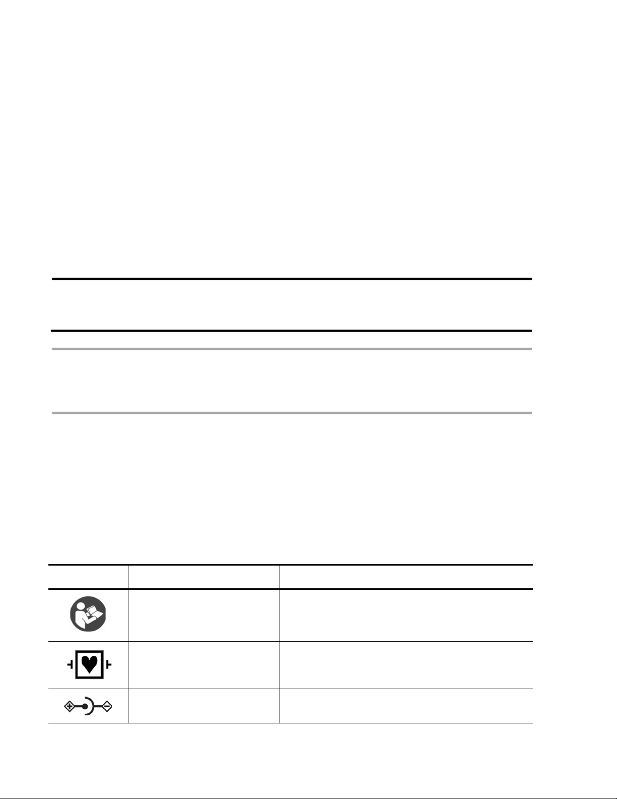
Symbols Marked on the Cardiograph or Patient Interface Module (PIM)
Symbol Name Description
Attention; read the Instructions
for Use
Type CF
Defibrillator Proof
DC Polarity Indicates the polarity of the DC power connector.
See the PageWriter TC70 and PageWriter TC50
Cardiograph Instructions for Use.
ECG physio isolation is type CF, defibrillator proof.
Suitable for all patient applications including direct
cardiac application. System is in continuous operation.
i-i
Page 12
Safety Summary Symbols Marked on the Cardiograph or Patient Interface Module (PIM)
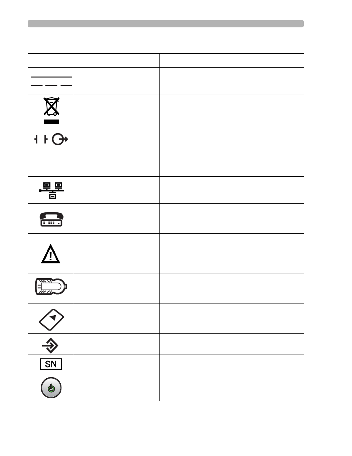
Symbols Marked on the Cardiograph or Patient Interface Module (PIM)
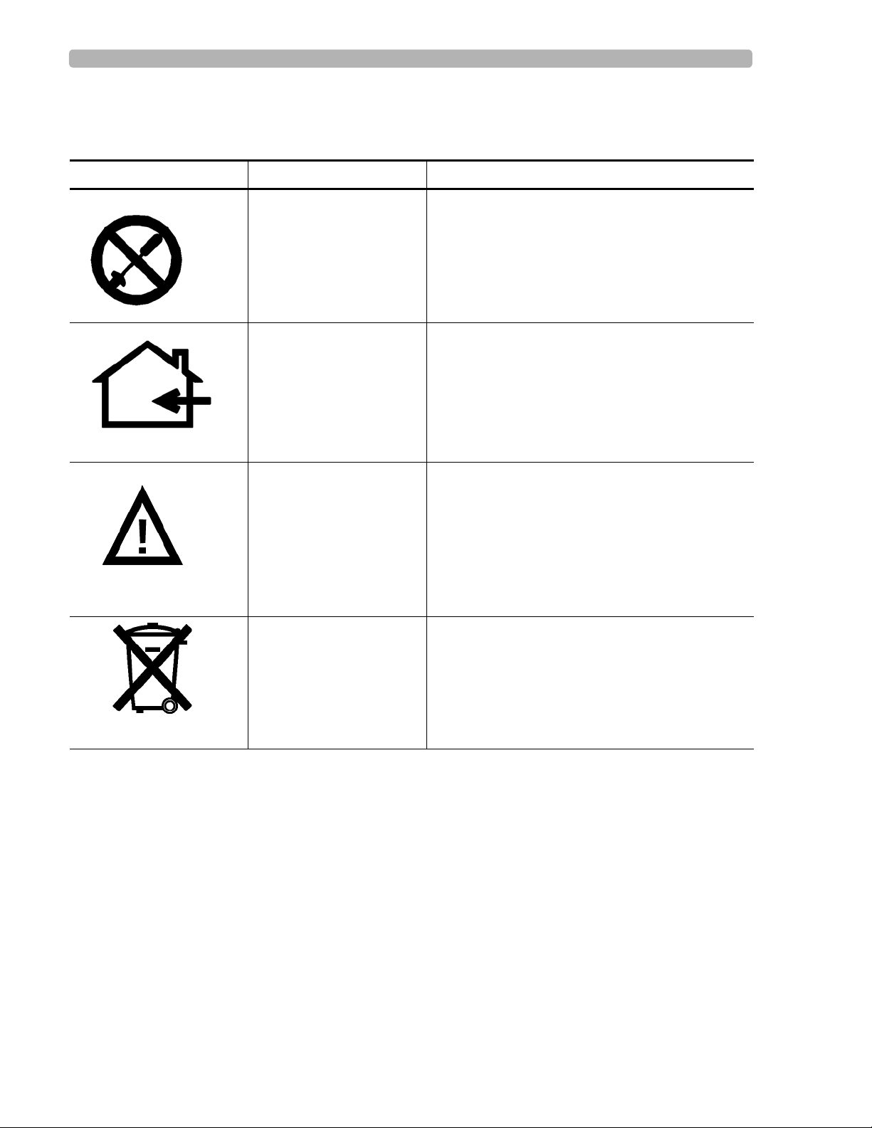
Symbol Name Description
Direct Current Indicates that the equipment is suitable for direct
current only.
Disposal Dispose of in accordance with the requirements of
your country.
ECG output signal The connector near this symbol provides access to an
analog ECG signal that can be used as a
synchronization signal for external devices, such as an
imaging device. This analog ECG signal is not
diagnostic quality and should not be used for ECG
analysis purposes.
Local Area Network (LAN)
Connector
Connect the Ethernet RJ45 LAN cable to the connector
directly above this symbol to establish LAN
connectivity.
Modem Connector Connect an analog phone line to the connector d irectly
above this symbol.
Attention; read the Instructions
for Use
Patient Interface Module (PIM)
Connector
See the PageWriter TC70 and PageWriter TC50
Cardiograph Instructions for Use.
Connect the PIM patient data cable to the connector
located directly above this symbol.
PCMCIA icon Insert the wireless LAN card into the slot located
directly above this symbol.
PS/2 Connector Connect the Magnetic Card Reader or Barcode Reader
to the connector located directly above this symbol.
Serial Number The number next to this symbol is the serial number of
the cardiograph.
Standby Pressing the button with this symbol on it puts the
cardiograph into Standby (power saving mode).
i-ii PageWriter TC50/TC70 Cardiograph Instructions for Use
Page 13

Symbols Marked on the Cardiograph or Patient Interface Module (PIM) Safety Summary
Symbols Marked on the Cardiograph or Patient Interface Module (PIM)
Symbol Name Description
USB Connector The connector near this symbol is used with a USB
device.
Non-ionizing electromagnetic
radiation
Interference may occur in the vicinity of equipment
marked with this symbol.
Equipotential Grounding Post Equipotential grounding post used for establishing
common ground between instruments.
Class II Protection against electric shock (PageWriter TC70
Cardiograph only).
Fuse The PageWriter TC50 Cardiograph contains a 1 .6 amp
(250V) time-delay fuse.
PageWriter TC50/TC70 Cardiograph Instructions for Use i-iii
Page 14
Safety Summary Safety Symbols Marked on the Cardiograph Packaging
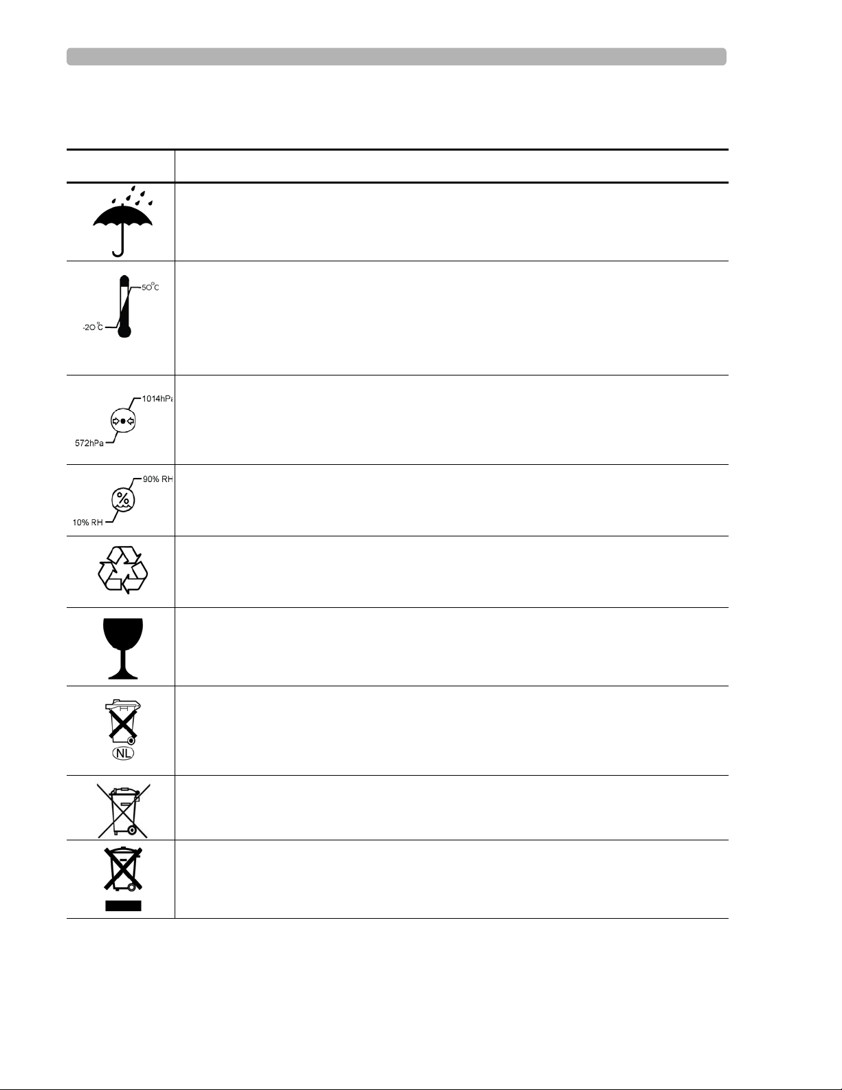
Safety Symbols Marked on the Cardiograph Packaging
Symbol Description
Keep dry.
o
Ambient temperature range of -20
transport and storage.
Note: the batteries will discharge at a rapid rate if the cardiograph is stored at a high
temperature.
Atmospheric pressure range of 0 to 4572 meters (15,000 feet), 572 hPA above sea level
for transport and storage.
C (-4o F) to 50 oC (122o F) (non-condensing) for
Relative humidity range of 10% to 90% (non-condensing) for transport and storage.
Made from recycled materials.
Fragile.
Lithium ion battery. Do not dispose of in trash. Follow local regulations for disposing of
as small chemical waste.
This product consists of devices that may contain mercury, which must be recycled or
disposed of in accordance with local, state, or federal laws. (Within this system, the
backlight lamps in the monitor display contain mercury.)
Dispose of in accordance with the requirements of your country.
i-iv PageWriter TC50/TC70 Cardiograph Instructions for Use
Page 15
Safety and Regulatory Symbols Marked on the PageWriter TC70 Cardiograph Cart Safety Summary
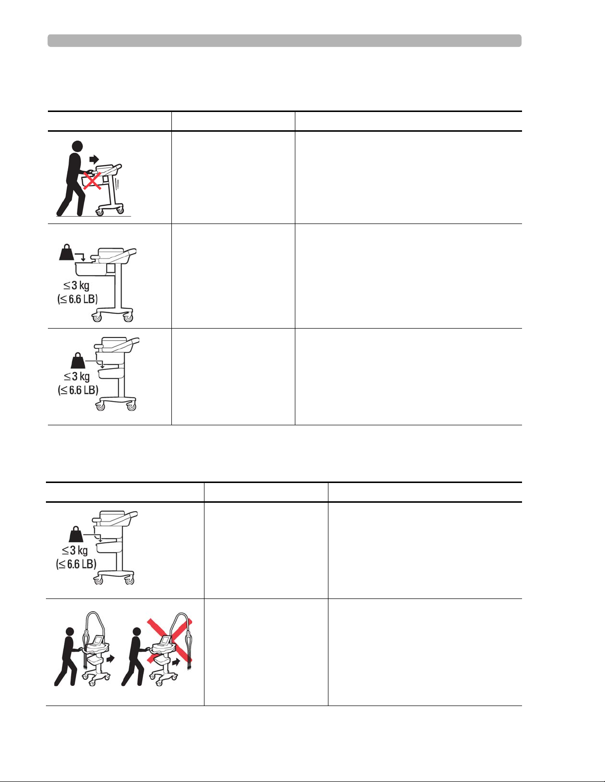
Safety and Regulatory Symbols Marked on the PageWriter TC70 Cardiograph Cart
Symbol Name Description
Cart Transport Do not transport the cart with the drawer open.
Cart Drawer Weight
Limit
Cart Storage Bin Weight
Limit
Do not place more than 3 kilograms or 6.6
pounds of weight into the cart drawer.
Do not place more than 3 kilograms or 6.6
pounds of weight into the cart storage bin.
Safety and Regulatory Symbols Marked on the PageWriter TC50 Cardiograph Cart
Symbol Name Description
Cart Storage Bin Weight
Limit
Do not place more than 3 kilograms or 6.6
pounds of weight into the cart storage bin.
Optional Patient Cable
Arm
PageWriter TC50/TC70 Cardiograph Instructions for Use i-v
Do not transport the cart with the patient
cable arm positioned to the side. Only
transport the cart with the patient cable
arm positioned to the front of the cart.
Page 16
Safety Summary Safety and Regulatory Symbols Marked on the PageWriter TC70 Cardiograph AC Power Adapter
Safety and Regulatory Symbols Marked on the PageWriter TC70 Cardiograph AC Power Adapter
Symbol Name Description
No serviceable parts
inside
Indoor, dry location use
only
Attention; read the
Instructions for Use
There are no serviceable parts inside the AC
adapter. Do not open the AC adapter case.
The AC adapter is only intended for indoor use in
a dry location.
See the PageWriter TC70 and PageWriter TC50
Cardiograph Instructions for Use for information
on the AC power adapter.
AC adapter disposal Dispose of in accordance with the requirements
of your country.
i-vi PageWriter TC50/TC70 Cardiograph Instructions for Use
Page 17

Accessories and Supplies Important Patient and Safety Information
Important Patient and Safety Information
The PageWriter TC70 cardiograph and PageWriter TC50 cardiograph isolate all connections
to the patient from electrical ground and all other conductive circuits in the cardiograph. This
reduces the possibility of hazardous currents passing from the cardiograph through the
patient’s heart to ground.
WARNING Failure to follow these warnings could affect both patient and operator safety.
Accessories and Supplies
WARNING Always clean and disinfect reusable electrodes before patient use. Failure to properly
clean and disinfect reusable electrodes before patient use may cause infectious materials
to be transferred between patients.
WARNING The Welsh bulb electrodes (available as an accessory for the cardiograph) do not meet
the requirements of IEC 60601-2-25 for defibrillation recovery time, and cannot be
reliably used for patient diagnosis immediately following defibrillation.
WARNING When using additional peripheral equipment powered from an electrical source other
than the cardiograph, the combination is considered to be a medical system. It is the
responsibility of the operator to comply with IEC 60601-1-1 and test the medical system
according to the requirements. For additional information contact Philips Medical
Systems.
WARNING Do not use non-medical peripherals within 6 feet of a patient unless the non-medical
peripherals receive power from the cardiograph or from an isolation transformer that
meets medical safety standards.
CAUTION The Welsh bulb electrodes contain natural rubber latex which may cause allergic reactions.
CAUTION The use of equipment that applies high frequency voltages to the patient (including electrosurgical
equipment and some respiration transducers) is not supported and may produce undesired results.
CAUTION Only use Philips Medical Systems replacement parts and supplies with the cardiograph. The use of non-
approved replacement parts and supplies with the cardiograph is strictly prohibited. Cardiograph
safety and performance are not guaranteed when non-approved replacement parts and supplies are
used with the cardiograph.
PageWriter TC50/TC70 Cardiograph Instructions for Use i-vii
Page 18

Important Patient and Safety Information AC Power Adapter and AC Power Cord
Using accessories, peripherals, or cables that are not supplied with the cardiograph or that
are not recommended by Philips Medical Systems can result in increased emissions or
decreased immunity of the cardiograph.
Connect other equipment in accordance with IEC 60601-1-1 Medical Electrical Systems
Standard or IEC 60601-1: 2005 (3rd Edition) Medical Electrical Equipment Standard
Clause 16 Medical Electrical Systems.
When connecting the cardiograph to other AC powered equipmen t, only connect e quipment
approved to IEC 60601-1 Medical Electrical Equipment or IEC 60950-1 Information
Technology Equipment.
Only use patient electrodes that are approved by Philips Medical Systems. The use of non-
approved patient electrodes may degrade cardiograph performance.
T o prevent burns to the pat ient, remove all ECG electrodes and lead wires prior to the use of
high frequency surgical equipment (including electrosurgical equipment and some
respiration transducers).
AC Power Adapter and AC Power Cord
WARNING Only use the external power supply with part number 453564094411 with the
PageWriter TC70 cardiograph in order to prevent electrical safety hazards. The use of
any other power supply is not approved by Philips Medical Systems.
WARNING Whenever the AC power cord is connected to a live power outlet, ensure that it is also
securely attached to the cardiograph. Always disconnect the AC power cord from the
power outlet when it is not connected to the cardiograph.
WARNING Only use grounded power cords (three-wire power cords with grounded plugs) and
grounded electrical outlets that are labeled as Hospital Only or Hospital Grade. NEVER adapt a
grounded plug to fit an ungrounded outlet by removing the ground prong. Use the
equipotential post when redundant earth ground is necessary according to IEC 60601-1-
1.
CAUTION The power supply could feel warm to the touch.
.The PageWriter TC70 cardiograph external po wer supply, part number 453564094411, is
designed with a three wire supply system. The ground only serves a functional purpose for
EMC and not protective earth for electrical safety. Use of an appropriate three-wire power
cord is necessary to provide proper EMC operation.
i-viii PageWriter TC50/TC70 Cardiograph Instructions for Use
Page 19

Analog ECG Output Signal Port Important Patient and Safety Information
Only use the AC power adapter designed to be used with the PageWriter TC70 cardiograph,
part number 453564094411 , in order to ensure continue d compliance with the requirements
of IEC 60601-1.
To disconnect the cardiograph from AC power, unplug the cardiograph AC power cord
from the mains power supply.
This equipment complies with the earth leakage current limits as specified in UL 60601-
1:2003 Medical Electrical Equipment - General Requirements for Safety, only when
connected to a 120 Volt mains power supply.
Periodically inspect the patient data cable, lead wires, and AC power cord for any worn or
cracked insulation. Ensure that no exposed wires are visible on the AC power cord.
Only use the Philips Medical Systems AC power cord (part number 453564094411)
supplied with the cardiograph. Use of any other power supply has not been verified and may
lead to operator or patient harm, including electrical shock. Periodically inspect the AC
power cord and AC power connector to ensure that both are in a safe and operable
condition. If the AC power cord or AC power connector is not in a safe or operable
condition, operate the cardiograph on battery power and contact Philips Medical Systems
for service.
Analog ECG Output Signal Port
Do not use the analog ECG output signal port (not supported on cardio graph) for diagno stic
purposes and do not use this signal for critical synchronization timing.
Do not connect any equipment to the cardiograph analog ECG output signal port that does
not meet medical safety requirements and that has not been evaluated by local safety
personnel.
Batteries
CAUTIONS Before removing and replacing batteries from the cardiograph, press down and hold the On/
Standby button ( ) (located on the front of the cardiograph), to shut down the cardiograph.
Ensure that the cardiograph is shut down. When the cardiograph is fully shut down, the screen is
black, and the On/Standby button is not illuminated. Once the cardiograph is shut down, proceed
to remove and replace the batteries.
When removing batteries from the cardiograph, the batteries could feel warm to the touch.
The battery capacity for the PageWriter TC50 cardiograph with a single battery installed
using the battery with Philips part number 989803170371, is 30 minutes of continuous
Rhythm printing, or 30 total ECG reports.
When operating the PageWriter TC50 cardiograph with one battery installed, only use the
Philips battery with part number 989803170371. Do not use the battery with Philips part
number 989803160981 for one battery operation.
When operating the PageWriter TC70 or the PageWriter TC50 cardiograph with two
batteries installed, ensure that both batteries contain the same Philips part number. The
PageWriter TC50/TC70 Cardiograph Instructions for Use i-ix
Page 20

Important Patient and Safety Information PageWriter TC50 Cardiograph One Battery Operation
battery part number identification label is found on the bottom of the battery. The
cardiograph cannot operate with two batteries that contain different part numbers. If the
cardiograph is operated with two batteries with different part numbers, the cardiograph will
display an error message and will not operate.
PageWriter TC50 Cardiograph One Battery Operation
The PageWriter TC50 cardiograph with inst alled software version A.04.00 and h igher can
operate on a single battery with Philips part number 989803170371.
The battery capacity for the PageWriter TC50 cardiograph with a single battery installed
using the battery with Philips part number 989803170371, is 30 minutes of continuous
Rhythm printing, or 30 total ECG reports.
When operating the PageW riter TC50 cardiograph with one battery installed, only use the
Philips battery with part number 989803170371. Do not use the battery with Philips part
number 989803160981 for one battery operation.
When operating the PageWriter TC50 cardiograph with one battery installed, the single
battery may be inserted into either battery compartment.
Cart
Ensure that the cardiograph is securely attached to the cardiograph cart before use.
Defibrillation
WARNING Do not touch the patient, patient data cable, leads, or the cardiograph during
defibrillation. Death or injury may occur from the electrical shock delivered by the
defibrillator.
Diagrams
Upon customer request, Philips Medical Systems will make available circuit diagrams,
component part lists, descriptions, calibration instructions and other technical information.
Display Accuracy
The accuracy of the ECG signals are within +/- 5% (or +/- 40 uV whichever is greater), over
a range of 0 to 5 mV, in the presence of differential and common mode DC offset voltages
of +/- 300 mV. The cardiograph performance is tested to comply with the accuracy
requirements over the dynamic ranges and frequency ranges specified in the IEC 60601-251 and AAMI EC-11 standards.
For additional details regarding accuracy and precision, refer to the Physician's Guide and
the Manufacturer's Disclosure Statement.
i-x PageWriter TC50/TC70 Cardiograph Instructions for Use
Page 21

ECG Interpretation Important Patient and Safety Information
ECG Interpretation
CAUTION Always enter accurate patient information (including age and gender) if using the Philips DXL ECG
Algorithm or Philips 12-Lead Algorithm for ECG interpretation.
Electrodes
Philips recommends the use of disp osable elec trodes at all times for all patient applications.
Choose either adult or pediatric disposable electrodes based on the age and size of the
patient. See “Disposable and Reusable Electrodes” on page 1-48 for information on
ordering disposable electrodes.
Faxed ECGs
CAUTION No guarantee is made as to the suitability of a faxed ECG for any particular purpose, due to the
variability inherent in fax technology.
CAUTION Faxed ECGs should only be sent to secure recipient fax machines.
General Cardiograph Use
WARNING Electrical shock hazard. Keep the cardiograph, Patient Interface Module (PIM), and all
cardiograph accessories away from liquids. Do not immerse the cardiograph, PIM, or
other accessories in any liquids.
WARNING Do not use this cardiograph near flammable anesthetics. It is not intended for use in
explosive environments or in operating rooms. The disconnection or connection of AC
power, or electrostatic discharge (ESD) may result in an electrical spark.
CAUTION The cardiograph may generate electromagnetic interference (EMI) that may cause nearby equipment
to fail.
CAUTION The use of equipment that applies high frequency voltages to the patient (including electrosurgical
equipment and some respiration transducers) is not supported and may produce undesired results.
Disconnect the patient data cable from the cardiograph, or detach the leads from the patient prior to
performing any procedure that uses high frequency surgical equipment.
PageWriter TC50/TC70 Cardiograph Instructions for Use i-xi
Page 22

Important Patient and Safety Information IEC 60601-2-51
The use of non-Philips equipment connected to, or operating with, the PageWriter TC70
cardiograph or the PageWriter TC50 cardiograph is not tested or supported, and may
produce undesired results.
Connecting multiple cardiographs to the same patient may pose a safety hazard due to the
summation of leakage currents. Any combination of instruments should be evaluated by
local safety personnel before being put into service.
IEC 60601-2-51
For information on the standard IEC 60601-2-51, please go to the Philips InCenter web site
(
incenter.medical.philips.com). For information on using the Philips InCenter site, see page 1-
5.
Lead Wires
WARNING Electrical shock hazard. Do not touch accessible connector pins and the patient
simultaneously.
WARNING Do not touch any loose or exposed leads during defibrillation. Death or injury may occur
from the electrical shock delivered by the defibrillator.
WARNING Ensure that the electrodes or lead wires do not come in contact with any other
conductive materials (including earth-grounded materials) especially when connecting or
disconnecting electrodes to or from a patient.
Main Waveform Display Screen
Manual measurements of ECG intervals and magnitudes should be performed on printe d
ECG reports only . Do not make manual measurements of ECG intervals and magnitudes on
the main waveform display screen since these ECG representations are scaled.
Modem Card and Fax Feature
WARNING Do not connect the modem card to a phone line when the cardiograph is connected to a
patient.
i-xii PageWriter TC50/TC70 Cardiograph Instructions for Use
Page 23

Pacemaker Important Patient and Safety Information
WARNING Only connect the phone line to the modem connector ( ) located on the rear panel
of the cardiograph. Never attach the phone line to the LAN connector ( ).
No guarantee is made as to the suitability of a faxed ECG report for any particular purpose,
due to the variability inherent in fax technology.
Pacemaker
Pace pulses may not be visible on a printed ECG report that uses simultaneous acquisition.
Patient Data Cable
WARNING The Philips Medical Systems patient data cable (supplied with cardiograph) is an integral
part of the cardiograph safety features. Use of any other patient data cable may lead to
the distortion or corruption of patient ECG data, may compromise defibrillation
protection and degrade cardiograph performance, and overall cardiograph safety may be
seriously degraded.
WARNING Ensure that the patient data cable is securely connected to the PIM Connector ( )
on the rear panel of the cardiograph.
The PageWriter TC50 cardiograph with installed software version A.03.00 and higher are
only compatible with the Class B patient data cable (Philips part number 989803164281).
Keep the patient data cable away from power cords and any other electrical equipment.
Failure to do so can result in AC power line frequency interference on the ECG trace.
Periodically inspect the patient data cable for any cracks or breaks in the cable insulation. If
the integrity of the patient data cable is not assured, replace the patient data cable. Contact
Philips Medical Systems for further assistance, see "Contacting a Philips Response
Center" on page 1-51.
Patient Interface Module (PIM)
WARNING Always clean and disinfect the Patient Interface Module (PIM) after patient use, if the
PIM comes into direct contact with the patient’s skin. Failure to properly clean and
disinfect the PIM after direct contact with the patient’s skin may cause infectious
materials to be transferred between patients.
PageWriter TC50/TC70 Cardiograph Instructions for Use i-xiii
Page 24

Important Patient and Safety Information Printer
CAUTION If using the optional, 16-lead PIM, always ensure that the leads connected to the Patient Interface
Module (PIM) are the same leads that are displayed on the cardiograph screen.
The PageWriter TC50 cardiograph with installed software version A.03.00 and higher is
only compatible with the Class B 12-lead PIM (Philips part number 453564150741, AAMI
and 453564150761, IEC) or the Class B 16-lead PIM (Philips part number 453564150751,
AAMI and 453564150771, IEC).
Always put the cardiograph in Standby before replacing the Patient Interface Module
(PIM). Do not change the PIM while the cardiograph is in active use.
Printer
CAUTION Do not pull on the paper while an ECG report is being printed. This can cause distortion of the
waveform and can lead to potential misdiagnosis.
Servicing the Cardiograph
Only qualified personnel may service the cardiograph or may open the cardiograph housing
to access internal cardiograph components. Do not open any covers on the cardiograph.
There are no internal cardiograph components that are serviced by the operator.
The Philips Medical Systems warranty is applicable only if you use Philips Medical
Systems approved accessories and replacement parts. See “Supplies and Ordering
Information” on page 1-45 for more information.
Software
WARNING Only install Philips Medical Systems software on the cardiograph. The installation or use
of software not approved by Philips Medical Systems is strictly prohibited and
cardiograph safety and performance are not guaranteed.
Touch Screen
WARNING Do not use sharp objects with the touch screen or apply excessive force to the touch
screen. Applying excessive force to the touch screen may result in breaking the touch
screen display and can cause sharp, jagged parts to expel to persons nearby.
Manual measurements of ECG intervals and magnitudes should be performed on printe d
ECG reports only . Do not make manual measurements of ECG intervals and magnitudes on
the touchscreen display since these ECG representations are scaled.
i-xiv PageWriter TC50/TC70 Cardiograph Instructions for Use
Page 25

USB Memory Stick The PageWriter TC70 Cardiograph and PageWriter TC50 Cardiograph
USB Memory Stick
WARNING Do not use the USB memory stick to import ECGs from other cardiographs, or other
non-Philips devices onto the PageWriter TC70 cardiograph or PageWriter TC50
cardiograph.
CAUTIONS Only use the USB memory stick that is available for purchase as an optional accessory from Philips
Medical Systems with the PageWriter TC cardiograph.
Do not insert a USB memory stick into the cardiograph, or remove a USB memory stick from the
cardiograph when the cardiograph is acquiring ECG data from the patient.
Only use the USB memory stick to transfer data between the cardiograph and a computer. Do not use
the USB memory stick with other devices.
Keep all USB memory sticks that contain patient data in a secure location where they cannot be
accessed by unauthorized personnel. Always delete patient data from a USB memory stick promptly
after use.
Affix a label to all USB memory sticks that contain patient data notifying users that unauthorized
access of patient data on the USB memory stick is punishable by law.
Periodically inspect the USB connectors (side and rear of cardiograph) for any cracks or
breaks. If the integrity of a USB connectors is not assured, do not use the USB connector,
and contact Philips Medical Systems for further assistance, see "Contacting a Philips
Response Center" on page 1-51.
The PageWriter TC70 Cardiograph and PageWriter TC50 Cardiograph
These Philips products are intended to be used and operated only in accordance with the safety
procedures and operating instructions provided in this Instructions for Use, and for the
purposes for which it was designed. The purposes for which the product is intended are
provided below. However, nothing stated in this Instructions for Use reduces the
responsibility of the user for sound clinical judgment and best clinical procedures.
Intended Use
The intended use of the cardiograph is to acquire multi-channel ECG signals from adult and
pediatric patients from body surface ECG electrodes and to record, display, analyze, and store
these ECG signals for review by the user. The cardiograph is to be used in healthcare facilities
by trained healthcare professionals. Analysis of the ECG signals is accomplished with
algorithms that provide measurements, data presentations, graphical presentations, and
interpretations for review by the user.
The interpreted ECG with measurements and interpretive statements is offered to the clinician
on an advisory basis only. It is to be used in conjunction with the clinician's knowledge of the
patient, the results of the physical examination, the ECG tracings, and other clinical findings.
PageWriter TC50/TC70 Cardiograph Instructions for Use i-xv
Page 26

The Philips ECG Algorithm Indications for Use
A qualified physician is asked to overread and validate (or change) the computer-generated
ECG interpretation.
Indications for Use
The cardiograph is to be used where the clinician decides to evaluate the electrocardiogram of
adult and pediatric patients as part of decisions regarding possible diagnosis, potential
treatment, effectiveness of treatment, or to rule out causes for symptoms.
The Philips ECG Algorithm
The PageWriter TC70 cardiograph and PageWriter TC50 cardiograph software uses the
Philips ECG Algorithm. The algorithm in the software analyzes the morphology and rhythm
on each of the 16 leads and summarizes the results. The set of summarized measurements is
then analyzed by the clinically-proven ECG Analysis Program.
16-lead reports may include or exclude ECG measurements, reasons, or analysis statements.
Intended Use
The intended use of the Philips ECG Algorithm is to analyze multi-channel ECG signals from
adult and pediatric patients with algorithms that provide measurements, data presentations,
graphical presentations, and interpretations for review by the user.
The interpreted ECG with measurements and interpretive statements is offered to the clinician
on an advisory basis only. It is to be used in conjunction with the clinician's knowledge of the
patient, the results of the physical examination, the ECG tracings, and other clinical findings.
A qualified physician is asked to overread and validate (or change) the computer-generated
ECG interpretation.
Indications for Use
The Philips ECG Algorithm is to be used where the clinician decides to evaluate the
electrocardiogram of adult and pediatric patients as part of decisions regarding possible
diagnosis, potential treatment, effectiveness of treatment, or to rule out causes for symptoms.
i-xvi PageWriter TC50/TC70 Cardiograph Instructions for Use
Page 27

1
1Getting Started
Welcome to the PageWriter TC70 and TC50 cardiographs, a versatile and powerful addition
to your cardiac care patient workflow. The PageWriter TC cardiographs help to simplify
patient cardiac care through easy-to-use 1-2-3 touch screen operation, color-coded signal
quality indicators, and integrated connectivity with the TraceMaster ECG Management
System for one touch patient order download and ECG transmission. The PageWriter TC70
and TC50 cardiographs also support integrated connectivity with an ADT Order Update
system. Powerful clinical features include the Philips DXL ECG Algorithm that provides
comprehensive measurement and interpretive analysis for up to 16 leads, and includes full
pediatric interpretation, enhanced pacemaker pulse detection, lead reversal detection
notification, and the Critical Values feature that provides an alert to caregivers of a silent MI
or other conditions that require immediate treatment, an integral tool for acute care
environments. Other time-sensitive clinical tools include ST Map reports that indicate ST
elevation, along with optional culprit artery identification that locates the probable anatomical
site of a coronary artery occlusion responsible for an ischemia. Support for up to 16 leads
assists in the precise detection of right sided or posterior myocardial injury in adults,
conditions that are difficult to diagnosis or detect in standard 12-lead ECGs. For pediatric
patients, the use of 15 leads provides full information on the electrical activity of the right
ventricle of the heart, crucial information for the accurate diagnosis of pediatric patients.
This PageWriter TC70 and PageWriter TC50 Cardiograph Inst ruct ions for Use and the other
components provided in the Learning Kit describe all aspects of setting up, using, and
maintaining your cardiograph.
NOTE Read and complete the materials included in the PageWriter TC70/TC50 Cardiograph Learning Kit
before using the cardiograph. Pay close attention to all warnings and cautions.
1-1
Page 28

Getting Started PageWriter TC70/TC50 Cardiograph Learning Kit
A
B
C
D
PageWriter TC70/TC50 Cardiograph Learning Kit
Philips Medical Systems provides detailed instructional and reference materials in the
PageWriter TC70/TC50 Cardiograph Learning Kit.
The PageWriter TC70/TC50 Cardiograph Learning Kit contains the Quick Help Guide, User
Skills Checklists, and the User Documentation and Training DVD.
Figure 1-1 The PageWriter TC70/TC50 Cardiograph Learning Kit
About the PageWriter TC70/TC50 Cardiograph Learning Kit
Getting Started Guide (A)
This fold out guide Guide provides out-of-the-box instructions for setting up the
cardiograph. It is intended to be used with the instructions provided in this chapter.
1-2 PageWriter TC70/TC50 Cardiograph Instructions for Use
Page 29

Getting Started PageWriter TC70/TC50 Cardiograph Learning Kit
User Documentation and Training DVD (B)
The user documentation and training DVD includes many useful files including:
– Philips DXL ECG Algorithm Physician’s Guide
This Physician’s Guide provides a comprehensive description of the Philips DXL
ECG Algorithm version PH100B, and lists all of the interpretive statements included
in the 0B criteria.
– Philips 12-Lead Algorithm Physician’s Guide
This Physician’s Guide provides a comprehensive description of the Philips 12-Lead
Algorithm version PH090A, and lists all of the interpretive statements included in the
0A criteria.
– PageWriter TC Cardiograph Network Configuration Guide (only available in
English)
This Network Configuration Guide provides detailed instructions on installing and
configuring wired or wireless network connectivity between the cardiograph and the
TraceMaster ECG Management System (including the OrderVue order handling
option), or other third party ECG management system.
– PageWriter TC Cardiograph Service Manual (only available in English)
This document provides comprehensive information on product troubleshooting,
performance verification and safety tests, using the Service Utilities accessed from the
Setup menu, and installing software upgrades.
– Metrologic Scanner Instructions for Use (only available in English)
This document provides comprehensive information on using and configuring the
optional barcode scanner available with the cardiograph, and also provides detailed
calibration sequences for configuring the barcode scanner for use with extended Code
39 barcode standards.
– PageWriter TC70 and PageWriter TC50 Cardiograph Interactive Training Program
for software version A.02.00 (only available in English)
This training program provides detailed information on the purpose of 12 and 16-lead
ECGs, the different views of the heart that the ECG represents, electrode placement
for 12 or 16 leads, effective patient preparation, basic cardiograph operation, and how
to troubleshoot various ECG signal quality problems. The training program also
includes interactive, hands-on training exercises to test users on information provided
in the training program. Updates to this training program will be available on a
periodic basis, and may be downloaded from the Philips InCenter site. For more
information on accessing and using the Philips InCenter site, see “Using the Philips
InCenter Site" on page 1-5.
To open the User Documentation and Training DVD:
1
Insert the DVD into a DVD-compatible drive on a standard PC.
The main menu opens automatically. Click on a blue button or on the file name to
open a file.
NOTE If you save PDF files from the DVD to a PC hard drive, Acrobat Reader 9.0 will need to be
installed on the PC in order to view the files. For a free install, go to: www.adobe.com.
2
If the main menu does not automatically appear, open the DVD in W indows Explorer.
PageWriter TC70/TC50 Cardiograph Instructions for Use 1-3
Page 30

Getting Started Philips ECG XML Information
3 Double-click the file menu.pdf on the DVD. The main menu appears. Any of the files
on the DVD may be printed or saved to a PC hard drive
User Skills Checklists (C) (only available in English)
These checklists provide a comprehensive list of all of the tasks associated with patient
preparation, taking an ECG, and using the cardiograph features. These checklists provide
the basis for all critical tasks recommended for inclusion in a clinical training program.
These checklists can be copied as necessary, and retained as an official record of clinical
training at your facility. The checklists are also included as PDF files on the User
Documentation and Training DVD.
Quick Help Guide (D)
The Quick Help Guide is presented as an easy-to-use flip book that can be left at the
cardiograph in order to provide clear and simple instructions to users on using cardio graph
features. Included are instructions on proper patient preparation and electrode placement,
signal quality indicators, taking STAT or urgent ECGs, how to retrieve orders, and using
other cardiograph features. The guide is included as a PDF file on the User Documentation
and Training DVD, and additional copies may be printed if necessary. The PDF file is
sized appropriately for printing on standard sized paper.
Philips ECG XML Information
The PageWriter TC70 cardiograph and PageWriter TC50 cardiograph export ECG data in
XML (Extensible Markup Language) format. There are th ree avai lable XML sch ema versio ns
on the cardiograph: version 1.03, version 1.04, and version 1.04.01. Version 1.03 exports E CG
data in 12-lead format only, version 1.04 exports ECG data for up to 16 leads, and version
1.04.01 exports ECG data for up to 16 leads and includes full interpretation from the Philips
DXL Algorithm.
Information regarding the Philips ECG XML schema can be obtained directly from Philips
Medical Systems by sending an email request to:
name, facility, and the serial number of your PageWriter TC cardiograph in the email request.
NOTE The default XML version setting on the cardiograph must be coordinated with the XML version
compatibility of the TraceMaster ECG Management System, or other third party ECG management
system used by your facility. For more information on configuring your cardiograph for use with an
external ECG management system, see the PageWriter TC Network Configuration Guide included on the
User Documentation and Training DVD, or download the file from the Philips InCenter site.
ecg@philips.com. Please include your
1-4 PageWriter TC70/TC50 Cardiograph Instructions for Use
Page 31

Getting Started Using the Philips InCenter Site
Using the Philips InCenter Site
The Philips InCenter site provides frequent updates to all Philips Cardiac Systems product
documentation and product software, including the PageWriter TC70 and PageWriter TC50
cardiographs.
The Philips InCenter site requires an active registration and password. To register, go to the
InCenter site at:
(located under the user login and password fields). On the following page, under
Updates
Cardiac Systems InCenter Registration page appears. Complete all of the information fields on
the page to receive a login and password for the InCenter site.
Registration for the InCenter site requires the serial number of at least one PageWriter TC70
or PageWriter TC50 cardiograph in active use at your facility. The serial number is found on
the product identification label. The product identification label is located on the rear panel of
the cardiograph.
(lower right corner of page), click the Click here for account registration link. The
About Adobe Acrobat Versions
Adobe Acrobat Reader version 9.0 must be installed on the PC that is used to access the
Philips InCenter site. Previous versions of Acrobat Reader are not compatible with the Philips
InCenter site, and attempting to access InCenter with a previous version of Acrobat Reader
will result in error messages when opening documents. Uninstall all previous versions of
Acrobat Reader, and then proceed for a free install of Acrobat Reader 9.0 at:
incenter.medical.philips.com and click on the Need help? link on the main page
Software
www.adobe.com.
Any version of Adobe Acrobat Professional or Acrobat Elements are also not compatible with
the Philips InCenter site, and error messages will appear when opening documents with these
applications. Acrobat Reader 9.0 must be installed in addition to Acrobat Professional or
Acrobat Elements.
Follow this procedure when accessing documents on the Philips InCenter site.
To access documents on the Philips InCenter site:
Exit Acrobat Professional or Acrobat Elements (if open).
1
2 Start Acrobat Reader 9.0.
3 Open Internet Explorer , and go to the Philips InCenter site. Keep Acrobat Reader 9.0 open
the entire time while accessing the InCenter site.
PageWriter TC70 Cardiograph Components
The following sections include a description of all of the components of the PageWriter TC70
cardiograph, including the connection ports on the cardiograph, the Patient Interface Module
(PIM), and optional accessories available with the cardiograph. For more information on using
the cardiograph features, see “The Patient Session" on page 3-1. For information on ordering
any of the optional accessories for the cardiograph, see “Supplies and Ordering
Information" on page 1-45.
PageWriter TC70/TC50 Cardiograph Instructions for Use 1-5
Page 32

Getting Started PageWriter TC70 Cardiograph Components
A
B
DECF
G
H
Figure 1-2 PageWriter TC70 Cardiograph (left front view)
A Touch screen F ECG button
B Audio speaker G Paper tray
C AC power on indicator light H Keyboard
D Power/Standby button
E ID button
1-6 PageWriter TC70/TC50 Cardiograph Instructions for Use
Page 33

Getting Started PageWriter TC70 Cardiograph Components
I
J
Figure 1-3 PageWriter TC70 Cardiograph (right front view)
I Battery compartment
J USB memory stick connector
PageWriter TC70/TC50 Cardiograph Instructions for Use 1-7
Page 34

Getting Started PageWriter TC70 Cardiograph Components
H
D
C
B
A
E
F
G
Figure 1-4 PageWriter TC70 Cardiograph (rear view)
A Modem connector G Wireless LAN card slot (with protective
cover installed)
B LAN connector H AC power connector
C Barcode reader or magnetic card reader
connector
D Analog ECG output signal connecto r (not
supported)
E USB connector
F PIM connector
WARNING Do not connect the modem card to a phone line when the cardiograph is connected to a
patient.
CAUTION Do not insert a USB memory stick into the cardiograph, or remove a USB memory from the
cardiograph when the cardiograph is acquiring ECG data from a patient.
1-8 PageWriter TC70/TC50 Cardiograph Instructions for Use
Page 35

Getting Started PageWriter TC50 Cardiograph Components
A
B
D
E
C
F
GH I J
PageWriter TC50 Cardiograph Components
The following sections include a description of all of the components of the PageWriter TC50
cardiograph, including the connection ports on the cardiograph, the Patient Interface Module
(PIM), and optional accessories available with the cardiograph. For more information on using
the cardiograph features, see “The Patient Session" on page 3-1. For information on ordering
any of the optional accessories for the cardiograph, see “Supplies and Ordering
Information" on page 1-45.
Figure 1-5 PageWriter TC50 Cardiograph (right front view)
A Touch screen F Keyboard
B Audio speakers G AC power on indicator light
C Battery compartment H Power/Standby button
D USB memory stick connector I ID button
E Paper tray J ECG button
PageWriter TC70/TC50 Cardiograph Instructions for Use 1-9
Page 36

Getting Started PageWriter TC50 Cardiograph Components
H
D
C
B
A
E
F
G
I
Figure 1-6 PageWriter TC50 Cardiograph (rear view)
A Wireless LAN card slot (with protective cover
installed)
G Barcode reader or magnetic card reader
connector
B Equipotential grounding post H LAN connector
C AC power cord connector I Modem connector
D PIM connector
E USB connector
F Analog ECG output signal connector (not
supported)
WARNING Do not connect the modem card to a phone line when the cardiograph is connected to a
patient.
CAUTIONS Do not insert a USB memory stick into the cardiograph, or remove a USB memory from the
cardiograph when the cardiograph is acquiring ECG data from a patient.
Only use grounded power cords (three-wire power cords with grounded plugs) and grounded
electrical outlets that are labelled as Hospital Only or Hospital Grade. Never adapt a grounded plug to
fit an ungrounded outlet by removing the ground prong. Use the equipotential post when redundant
earth ground is necessary according to IEC 60601-1-1.
1-10 PageWriter TC70/TC50 Cardiograph Instructions for Use
Page 37

Getting Started Assembling the PageWriter TC70 Cardiograph Cart
Assembling the PageWriter TC70 Cardiograph Cart
The PageWriter TC70 cardiograph is available with an optional cart that includes a locking
storage drawer, storage bin, and a built-in holder for the PIM (patient interface module). The
instructions in this section describe the unassembled cart option. For information on ordering
the cart, see “PageWriter TC70 and PageWriter TC50 Cardiograph Supply Part Numbers" on
page 1-46.
To attach the cardiograph to a fully assembled cart, see Step 7 on page 1-13 .
CAUTION Follow the procedure below to ensure that the cardiograph is securely fastened to the cart before
use.
Figure 1-7 TC70 Unassembled Cart Kit Contents
To attach the cardiograph to the cart:
Insert the beam into the cart base.
1
PageWriter TC70/TC50 Cardiograph Instructions for Use 1-11
Page 38

Getting Started Assembling the PageWriter TC70 Cardiograph Cart
2 Hold the beam steadily. Turn the cart onto the side to expose the bottom of the cart.
3 Place the ground strap onto the screw end.
4 Attach the bolt screws and tighten using the provided wrench. Ensure that the bolt screws
are tightened to 80-100 in lbs.
1-12 PageWriter TC70/TC50 Cardiograph Instructions for Use
Page 39

Getting Started Assembling the PageWriter TC70 Cardiograph Cart
5 Turn the cart upright.
6 Attach the top shelf to the beam using the provided bolts and wrench. Tighten the bolts to
80-100 in lbs.
7 Align the rear feet of the cardiograph with the rear locking holes on the cart. Align the
front feet of the cardiograph with the front screw holes on the cart. Lower the cardiograph
onto the cart and snap into place.
PageWriter TC70/TC50 Cardiograph Instructions for Use 1-13
Page 40

Getting Started Assembling the PageWriter TC50 Cardiograph Cart
8 Insert the front screws through the bottom of the base, and tight en .
9 Slide the drawer onto the cart as shown.
Assembling the PageWriter TC50 Cardiograph Cart
The PageWriter TC50 cardiograph is available with an optional cart that includes a storage bin
and a built-in holder for the PIM (patient interface module). A second storage bin is available
as an optional accessory. The instructions in this section describe the unassembled cart option.
For information on ordering the cart, see “PageWriter TC70 and PageWriter TC50
Cardiograph Supply Part Numbers" on page 1-46.
To attach the cardiograph to a fully assembled cart, see Step 10 on page 1-18 .
CAUTION Follow the procedure below to ensure that the cardiograph is securely fastened to the cart before use.
1-14 PageWriter TC70/TC50 Cardiograph Instructions for Use
Page 41

Getting Started Assembling the PageWriter TC50 Cardiograph Cart
Figure 1-8 Unassembled Cart Kit Contents
To attach the cardiograph to the cart:
Insert the beam into the cart base.
1
PageWriter TC70/TC50 Cardiograph Instructions for Use 1-15
Page 42

Getting Started Assembling the PageWriter TC50 Cardiograph Cart
2 Hold the beam steadily. Turn the cart onto the side to expose the bottom of the cart.
3 Place the ground strap onto the screw end.
4 Attach the bolt screws and tighten using the provided wrench. Ensure that the bolt screws
are tightened to 80-100 in lbs.
1-16 PageWriter TC70/TC50 Cardiograph Instructions for Use
Page 43

Getting Started Assembling the PageWriter TC50 Cardiograph Cart
5 Turn the cart upright.
6 Attach the bin to the beam.
7 Insert the bin dividers as shown.
PageWriter TC70/TC50 Cardiograph Instructions for Use 1-17
Page 44

Getting Started Assembling the PageWriter TC50 Cardiograph Cart
8 Slide out the tray on the top shelf.
9 Attach the top shelf to the beam using the bolt screws. T ight en the bolts using the p rovided
wrench. Ensure that the bolt screws are tightened to 80-100 in lbs.
10 Align the rear feet of the cardiograph with the rear holes on the cart. Lower the front feet
of the cardiograph into the front holes on the cart and push the cardiograph into place.
Ensure that the cardiograph is locked into the slot on the front right of the cart.
1-18 PageWriter TC70/TC50 Cardiograph Instructions for Use
Page 45

Getting Started Using the Cart Wheel Positioners and Brake
11 Insert the screws through the bottom of the base, and tighten.
Using the Cart Wheel Positioners and Brake
Both cart models include one wheel brake and two wheel positioners. Lock the wheel
positioners at all times when using the cart. The wheel positioners keep the cart straight when
moving forward or backward, or when turning corners. The wheel positioners also help the
cart maneuver in tight spaces.
To use the cart wheel positioners and brake:
1
Align the front wheels so that they are straight. Step on both wheel positioners. Move the
cart forward until the wheels lock into position. The cart will move forward or backward
in a straight line.
PageWriter TC70/TC50 Cardiograph Instructions for Use 1-19
Page 46

Getting Started Patient Interface Module (PIM)
2 Step on the gray rear wheel brake to lock the cart wheels. The cart will not move. Step on
the wheel brake again to unlock the wheels.
Patient Interface Module (PIM)
The same Patient Interface Module (PIM) is used on both the TC70 and TC50 model
cardiographs. The PIM is a hand-held device that connects to the patient data cable. The PIM
is available in a standard 12-lead, or an optional 16-lead model. For information on
configuring the optional 16-lead PIM, see “Configuring the 16-Lead PIM" on page 1-26.
NOTE Figure 1-9 shows AAMI version PIMs.
Figure 1-9 16-lead (left) and 12-lead (right) Patient Interface Module (PIM)
1-20 PageWriter TC70/TC50 Cardiograph Instructions for Use
Page 47

Getting Started Patient Interface Module (PIM)
AB
About Class A and Class B Patient Data Cables and PIMs
Prior to August, 2009, PageWriter TC70 cardiographs with installed software version A.02.00
and lower were shipped from Philips Medical Systems with Class A patient data cables and
Class A PIMs. All PageWriter TC70 cardiographs and PageWriter TC50 cardiographs with
installed software version A.03.00 and higher are shipped from Philips Medical Systems with
Class B patient data cables and Class B PIMs.
The only visual difference between a Class A and a Class B PIM or patient data cable is the
number of connectors on the PIM, and the number of pins on the PIM connector end of the
patient data cable. All Class A devices have 5 connectors/pins on the PIM connector, and on
the PIM connector end of the patient data cable. All Class B devices have 8 connectors/pins on
the PIM connector, and on the PIM connector end of the patient data cable.
NOTE Both Class A and Class B patient data cables have 5 pins on the connector end that attaches to the
cardiograph.
Class A patient data cables can only be used with a Class A PIM on the PageWriter TC70
cardiograph. Class B patient data cables can only be used with a Class B PIM on either a
PageWriter TC70 or a PageWriter TC50 cardiograph. When ordering replacement patient data
cables or PIMs from Philips Medical Systems, check the number of connectors on the PIM,
and also check the number of pins on the PIM connector end of the patient data cable to ensure
that you are ordering the correct Class A or Class B device.
NOTE If you are unable to connect a patient data cable to a PIM connector, check that both devices are
compatible. You cannot connect a Class A patient data cable to a Class B PIM.
Figure 1-10 Class A and Class B Patient Data Cable Connectors
A Class A patient data cable (5 pins) B Class B patient data cable (8 pins)
PageWriter TC70/TC50 Cardiograph Instructions for Use 1-21
Page 48

Getting Started Patient Interface Module (PIM)
AB
Figure 1-11 Class A and Class B Patient Interface Module (PIM) Connectors
A Class A PIM (5 connectors) B Class B PIM (8 connectors)
Attaching the Patient Data Cable to the PIM and Cardiograph
The patient data cable must be attached to the PIM connector before use. Once attached to the
PIM, the patient data cable is then attached to the cardiograph through the appropriate PIM
connector on the rear of the cardiograph.
WARNING Ensure that the patient data cable is securely connected to the PIM connector ( )
on the rear panel of the cardiograph.
WARNING The Philips Medical Systems patient data cable (supplied with cardiograph) is an integral
part of the cardiograph safety features. Use of any other patient data cable may lead to
the distortion or corruption of patient ECG data, may compromise defibrillation
protection and degrade cardiograph performance, and overall cardiograph safety may be
seriously degraded.
NOTE The PageWriter TC50 cardiograph with installed software version A.03.00 and higher is only
compatible with the Class B patient data cable (Philips part number 989803164281).
1-22 PageWriter TC70/TC50 Cardiograph Instructions for Use
Page 49

Getting Started Patient Interface Module (PIM)
To attach the patient data cable to the PIM and to the cardiograph:
1
Align the raised dot on the top of the patient data cable connector with the front of the
PIM. Insert the patient data cable connector through the metal housing. Push the patient
data cable connector firmly into the PIM connector . The connector clicks when it is locked
into position.
NOTE If you are unable to connect a patient data cable to a PIM connector, check that both devices are
compatible. You cannot connect a Class A patient data cable to a Class B PIM. For more
information, see page 1-21.
2
Connect the other end of the patient data cable to the PIM connector port ( ) located
on the rear panel of the cardiograph. Align the raised circle on the cable connector upright
as shown in the figure. Turn the cable connector to the right to lock it into position.
PageWriter TC70/TC50 Cardiograph Instructions for Use 1-23
Page 50

Getting Started Patient Interface Module (PIM)
3 Drape the patient data cable over the top of the rear handle on the cart to help ensure that
the patient data cable does not drag on the ground.
To disconnect the patient data cable from the PIM:
Twist the end of the patient cable connector inside the metal housing and pull the
connector out.
Special Note about Patient Interface Module (PIM)
The PIM is an electronic device and can feel warm if placed on bare skin.
CAUTION If the PIM is placed on the patient’s bare skin, always place a sheet or cloth between the PIM and the
patient. If the PIM is left on the patient’s skin for an extended period of time while the cardiograph is
being used for monitoring purposes, the PIM could reach a maximum temperature of 46 °C (114.8 °F)
in a room environment with a temperature of 40 °C (104 °F).
1-24 PageWriter TC70/TC50 Cardiograph Instructions for Use
Page 51

Getting Started Patient Interface Module (PIM)
A
A
Figure 1-12 Placing PIM on patient’s skin
A Cloth placed between PIM and patient
PIM ECG Button
The PIM has an ECG button that is used to take ECGs from the bedside. For information on
connecting the PIM to the patient, or on using the PIM ECG button, see “The Patient Session”
on page 3-1.
Figure 1-13 The 16-Lead PIM with ECG button
A PIM ECG button
PageWriter TC70/TC50 Cardiograph Instructions for Use 1-25
Page 52

Getting Started Patient Interface Module (PIM)
A
B
C
D
Configuring the 16-Lead PIM
The optional 16-lead PIM may be configured to support up to 16 optional leads for adult and
pediatric application. The 16-lead PIM is shipped with four optional leads, color clip
identifiers, and shorting plugs. For information on ordering the 16-lead PIM option, see
“PageWriter TC70 and PageWriter TC50 Cardiograph Supply Part Numbers” on page 1-46.
CAUTION When using the 16-lead PIM, always ensure that the leads connected to the Patient Interface Module
(PIM) are the same leads that are displayed on the cardiograph screen.
Figure 1-14 16-Lead PIM Kit
A Color identification clips C Lead separator
B Optional leads (4 total) D Shorting plug (6 total)
To configure the 16-lead PIM:
1
Press the On/Standby button to put the cardiograph into Standby.
CAUTION Always put the cardiograph in Standby before connecting or disconnecting the Patient Interface
Module (PIM). Do not disconnect or connect the PIM to the cardiograph while the cardiograph is
in active use.
2 Disconnect the PIM from the cardiograph, if necessary.
3 There are six optional lead connectors available on the PIM. These optional lead
connectors include:
C3R/V3R, C4R/V4R, C5R/V5R, C7/V7, C8/V8 and C9/V9. Any of
these optional leads (up to a maximum of four) may be configured for use with the
cardiograph.
NOTE The cardiograph does not support the configuration of 18 leads. Any of the optional leads, up to a
maximum of 4, may be configured for use with the cardiograph.
1-26 PageWriter TC70/TC50 Cardiograph Instructions for Use
Page 53

Getting Started Patient Interface Module (PIM)
A
Figure 1-15 16-Lead PIM Optional Lead Connectors (AAMI/IEC)
A Optional lead connectors
Attach the appropriate color-coded identification clip (included in the lead kit) to the lead,
4
and attach the small color clip near the connector end of the lead wire.
Figure 1-16 Attaching the color clips to the lead
PageWriter TC70/TC50 Cardiograph Instructions for Use 1-27
Page 54

Getting Started Patient Interface Module (PIM)
5 Attach the lead to the correct lead connector on the PIM. If any lead connectors on the
PIM are left empty, insert a shorting plug (included in kit).
Figure 1-17 Shorting Plug (included in Lead Kit)
NOTE To configure the 16-lead PIM for standard 12 leads, insert shorting plugs into all of the optional
lead connectors.
6
Ensure that each lead is firmly connected to the PIM.
Recommended 16-Lead Configurations
Table 1-1 provides some suggested configurations of the 16-lead Patient Interface Module
(PIM) for adult and pediatric application.
NOTE The recommended 16-lead configuration options described in Table 1-1 are the only 16-lead options
that are compatible with the TraceMaster ECG Management System.
Table 1-1 15 and 16-Lead PIM Configuration Options
Lead Option Standard 12-leads plus extended
leads (AAMI/IEC)
Pediatric
V3R (C3R), V4R (C4R), V7 (C7)
(15 leads)
Posterior
V7 (C7), V8 (C8), V9 (C9)
(15 leads)
Lead Placement
1-28 PageWriter TC70/TC50 Cardiograph Instructions for Use
Page 55

Getting Started Installing the Batteries
Table 1-1 15 and 16-Lead PIM Configuration Options (continued)
Lead Option Standard 12-leads plus extended
leads (AAMI/IEC)
Balanced
(16 leads)
V3R (C3R), V4R (C4R), V7 (C7),
V8 (C8)
Installing the Batteries
The PageWriter TC70 cardiograph is shipped with two batteries, and the PageWriter TC50
cardiograph is shipped with one or an optional two batteries that are used to power the
cardiograph when AC power is not available.
Lead Placement
CAUTION Insert the batteries into the cardiograph before plugging the cardiograph into AC power.
Notes about Battery Installation
NOTES If operating the PageWriter TC50 cardiograph with one battery installed, the battery may be
inserted into either battery compartment.
When operating the PageWriter TC50 cardiograph with one battery installed, only use the Philips
battery with part number 989803170371. Do not use the battery with Philips part number
989803160981 for one battery operation.
When operating the PageWriter TC70 or PageWriter TC50 cardiograph with two batteries
installed, ensure that both batteries contain the same Philips part number. The battery part number
identification label is found on the bottom of the battery. The cardiograph cannot operate with two
batteries that contain different part numbers. If the cardiograph is operated with two batteries with
different part numbers, the cardiograph will display an error message and will not operate.
PageWriter TC70/TC50 Cardiograph Instructions for Use 1-29
Page 56

Getting Started Installing the Batteries
To install the batteries:
1
Open the battery door.
2 Locate the two gold pull tabs inside of the battery compartment. Pull the tabs straight out
of the battery compartment and lay flat.
1-30 PageWriter TC70/TC50 Cardiograph Instructions for Use
Page 57

Getting Started Installing the Batteries
3 Insert the battery with the external connector facing the bottom rear of the compartment.
NOTE If operating the PageWriter TC50 cardiograph with one battery installed, the battery may be
inserted into either battery compartment.
4
Push in the battery and ensure that the battery is fully inserted into the slot. The pull tab
will insert along with the battery. Insert the second battery following the same procedure.
PageWriter TC70/TC50 Cardiograph Instructions for Use 1-31
Page 58

Getting Started Installing the Batteries
5 Reinstall the battery door.
6 Connect the AC power cord to the cardiograph. Charge the batteries for five hours before
operating the cardiograph on battery power only.
Charging the Batteries
Charge the batteries for five hours prior to initial use. Plug the cardiograph into AC power
whenever possible, and fully charge the batteries. Proper battery maintenance and care,
including frequent and full charging of the batteries, will help to prolong battery life.
There are configurable power saving features available on the cardiograph. These features are
used to help prolong overall battery life, and to optimize battery power use between battery
charges.
CAUTION When removing the batteries from the cardiograph, the batteries could feel warm to the touch.
1-32 PageWriter TC70/TC50 Cardiograph Instructions for Use
Page 59

Getting Started Installing the Batteries
A
Calibrating the Batteries
The batteries may require periodic calibration to ensure the continued accuracy of the battery
power and overall battery status information displayed on the cardiograph. When battery
calibration is required, a message appears on the Battery Status window. For more information
on battery calibration, see “Battery Calibration” on page 5-12.
Battery Power Indicator
The battery power indicator ( ) appears on the Status Bar and is always visible. The
indicator displays the current battery power level. The cardiograph can operate on AC power
while the batteries are charging, but the batteries will charge at a slower rate.
Figure 1-18 Battery Power Indicator on the Status Bar
A Battery level indicator
PageWriter TC70/TC50 Cardiograph Instructions for Use 1-33
Page 60

Getting Started Installing the Batteries
To check the battery power level:
1
From any screen, tap on the battery icon on the Status Bar ( ). The Battery Status
window appears. This window provides detailed information on the status of the
cardiograph batteries. The battery icon indicates the overall charge status of the battery.
Table 1-2 Battery Icon (on Status Bar or Battery Status window)
Icon on Status Bar Battery Level
Fully Charged Battery
75% power capacity
50% power capacity
Low Battery Power:
red battery icon appears when power level is below
25%
cardiograph beeps and an error message appears until
the unit is plugged into AC power (audio feature may
be disabled)
tap the icon to see how many minutes are left of
operating battery power
If overall battery power is below 15% and the
cardiograph is in Standby, when the On/Standby button
is pressed it will flash green five times and the
cardiograph will be unable to return to active use. Plug
the cardiograph into AC power to recharge the
batteries.
No or Dead Battery
1-34 PageWriter TC70/TC50 Cardiograph Instructions for Use
Page 61

Getting Started Using the Wireless LAN Card
NOTE If the Plug in the Cardiograph message appears, the cardiograph needs to be plugged into AC
power immediately.
Figure 1-19 Battery Status Information with Plug in the Cardiograph message
2
Touch the Close button to close the window.
Using the Wireless LAN Card
The PageWriter TC70 cardiograph and PageWriter TC50 cardiograph both support the
Summit Wireless LAN card. The wireless LAN card is used to transfer ECG and order data
between the cardiograph and a TraceMaster ECG Management System. The cardiograph can
also be configured to transfer ECG data using a wireless connection to a third party ECG
management system. For information on configuring cardiograph connectivity with a
TraceMaster or other third party ECG management system, see the PageWriter TC70/TC50
Cardiograph Network Configuration Guide available on the User Documentation and
Training DVD, or the file can be downloaded from the Philips InCenter site.
CAUTION Only use wireless LAN cards with the PageWriter TC70 or PageWriter TC50 cardiographs that have
been purchased from Philips Medical Systems. The use of non-approved wireless LAN cards with
either model cardiograph is not tested or supported, and Philips Medical Systems does not guarantee
cardiograph operation or wireless LAN connectivity.
For information on installing the card and configuring the cardiograph for wireless
transmission, see the PageWriter TC Cardiograph Wireless LAN Installation Instructions. The
file is available for download from the Philips InCenter site (
incenter.medical.philips.com).
For information on ordering the wireless card, see “Supplies and Ordering Information" on
page 1-45.
PageWriter TC70/TC50 Cardiograph Instructions for Use 1-35
Page 62

Getting Started Using the Modem Card
Using the Modem Card
The modem card is an optional accessory that is used to fax ECGs to a configured receiving
fax machine, or is used to transfer ECGs or orders by modem between the cardiograph and a
TraceMaster ECG Management System. The cardiograph can also be configured to transfer
ECG data by modem to a third party ECG management system. For information on
configuring cardiograph connectivity with a TraceMaster or other third party ECG
management system, see the PageWriter TC70/TC50 Cardiograph Network Configuration
Guide available on the User Documentation and Training DVD, or the file can be downloaded
from the Philips InCenter site.
For information on ordering the modem card, see “Supplies and Ordering Information” on
page 1-45.
WARNING Do not connect the modem card to a phone line when the cardiograph is connected to a
patient.
Using the USB Memory Stick
The USB memory stick is an optional accessory that is used to transfer orders to the
cardiograph from a computer that has the WebSelect Utility installed, and can also be used to
transfer completed ECGs from the cardiograph to a TraceMaster ECG Management System
for reconciliation and processing. The USB memory stick can also be used to save custom
settings specified on the Setup screens as a Custom Settings file. This Custom Settings file can
then be transferred to additional cardiographs to help speed up the configuration process.
For information on using the WebSelect Utility, see the Using OrderVue with PageWriter
Cardiographs guide. This guide is available for download from the Philips InCenter site. For
information on the Philips InCenter site, see “Using the Philips InCenter Site" on page 1-5.
CAUTION The PageWriter TC70 and TC50 cardiographs only support the USB memory stick that is available for
purchase as an optional accessory from Philips Medical Systems. Philips does not guarantee that other
USB memory sticks are compatible with the PageWriter TC70 or TC50 cardiographs.
1-36 PageWriter TC70/TC50 Cardiograph Instructions for Use
Page 63

Getting Started Using the Barcode Reader
A
A
Figure 1-20 USB memory stick inserted into USB connector
A USB memory stick inserted into USB connector (tip illuminates when properly inserted)
The USB memory stick can store up to 200 ECGs and 200 orders. Ensure that the USB
memory stick is firmly inserted into the USB connector located on the front right side of the
cardiograph (next to the battery door). The tip of the USB memory stick illuminates when it is
properly inserted into the USB connector.
CAUTION Do not insert a USB memory stick into the cardiograph, or remove a USB memory stick from the
cardiograph when the cardiograph is acquiring ECG data from a patient.
CAUTION Only use the USB memory stick to transfer data between a PageWriter TC70 or TC50 cardiograph
and a computer. Do not use the memory stick with other devices.
Using the Barcode Reader
The barcode reader is an optional accessory that is used to quickly enter ID information by
scanning a barcode.
The barcode reader attaches to the barcode reader connector ( ) on the rear panel of the
cardiograph. Attach the barcode reader to the cardiograph before turning on AC power. For
information on ordering the barcode reader, see “Supplies and Ordering Information” on
page 1-45.
NOTE The Metrologic Scanner Instructions for Use, which provides complete information on configuring and
using the barcode scanner, is included on the User Documentation and Training DVD.
PageWriter TC70/TC50 Cardiograph Instructions for Use 1-37
Page 64

Getting Started Using the Cardiograph Touch Screen
Figure 1-21 The Barcode Reader
Using the Cardiograph Touch Screen
The touch screen provides access to all of the c ardiogra ph features. Simply touch the buttons
on the screen to open the different screens and to perform different functions.
1-38 PageWriter TC70/TC50 Cardiograph Instructions for Use
Page 65

Getting Started Using the Cardiograph Touch Screen
J
A B C
D
E
F
G
H
I
K
Touch Screen Overview
The touch screen is organized into different areas that are grouped by function. The following
sections provide an overview of each area of the touch screen.
Figure 1-22 Touch Screen Overview
Table 1-3 Touch Screen Overview
Touch Screen Item Feature Description
A
Selected Exam Type
The Exam Type selected for the current patient
session.
The available Exam Types are: Resting 12-
Lead
ECG.
Touch the button to change the selected Exam
Type.
, Resting Extended Lead, and Timed
PageWriter TC70/TC50 Cardiograph Instructions for Use 1-39
Page 66

Getting Started Using the Cardiograph Touch Screen
Table 1-3 Touch Screen Overview (continued)
Touch Screen Item Feature Description
B
C
D
Exam Layout
Current Operating
Settings
Status Bar
The settings underneath this button include the
selected ECG report layout settings, and the
level of interpretation generated by the Philips
12 or 16-lead algorithm that are being applied
to the selected Exam Type.
Any of the settings on this screen may be
edited, and the new settings are applied to the
current patient session.
The settings underneath this button include the
selected filters (Artifact, Baseline Wander),
pacing detection setting, and report scaling
settings being applied to the current patient
session.
The Unknown pacing setting is recommended
for most ECGs.
Displays information about the current cardiograph
settings, including selected Exam Type, current
patient name, network connectivity status, PIM
status, and the current date and time.
E
F
G
H
Waveform Display
Toolbar
Help
Setup
Display area for ECG waveforms. Lead connection
quality is indicated by the color of the waveform.
Press the up arrow ( ) or the down arrow ( )
key (on keyboard) to change the displayed lead
format.
All cardiograph ECG acquisition modes and ECG
management features.
Provides information on how to use the
cardiograph.
The settings underneath this button are used to
configure or change cardiograph settings, or to
access the service utilities. Access to these screens
may require entering a password.
1-40 PageWriter TC70/TC50 Cardiograph Instructions for Use
Page 67

Getting Started Using the Cardiograph Touch Screen
Table 1-3 Touch Screen Overview (continued)
Touch Screen Item Feature Description
I
ECG Storage and
Management Features
Provides access to the ECG Archive, which is
used as temporary storage for all ECGs
acquired on the cardiograph.
From the Archive, ECGs may be transferred to
a TraceMaster ECG Management System, or a
third party ECG management system.
From the Archive, a TraceMaster server may
be searched for previous ECGs to view and
print on the cardiograph.
The number on the button (9) displays the
number of ECGs currently stored in the
Archive.
J
Rhythm and Disclose
Features
The Rhythm feature is used to print continuous
rhythm strips of up to 12 or 16 selected leads
until the
The Disclose feature is used to review captured
Stop button is touched.
Events, to view continuous data from one
selected lead, or to print ECG reports in a
variety of formats.
The number on the Disclose button (0) displays
the number of Events currently stored in
Disclose.
K
1-2-3 Operation
Features
The Map, ID, and ECG buttons are used in
sequence to acquire and print a standard 12-lead or
16-lead ECG.
PageWriter TC70/TC50 Cardiograph Instructions for Use 1-41
Page 68

Getting Started Using the Cardiograph Touch Screen
B
A
Using the Main ECG Screen
The main screen displays 10 seconds of continuous ECG waveform data for each lead on one
single screen, or can display a split screen view with various views of continuous ECG
waveform data for each lead.
Figure 1-23 Main Screen with Split Screen View (12 Leads Displayed)
A Limb Leads B Precordial Leads
To change the lead display on the main screen:
1
Press the down arrow key (on keyboard) to display all leads on a split screen view.
The split screen view provides five seconds of continuous ECG waveform data for each
lead. The left side of the split screen displays the limb leads, and the right side displays all
precordial leads. Press the down arrow key (on keyboard) again to view additional
lead configurations.
2 Press the up arrow key (on keyboard) to change the display back to a standard 12, 15,
or 16-lead view with no split screen. The standard view provides ten seconds of
continuous ECG waveform data for each lead.
1-42 PageWriter TC70/TC50 Cardiograph Instructions for Use
Page 69

Getting Started Using the Cardiograph Touch Screen
ABC DEFGH
I
J
K
The Status Bar
The Status Bar (top of the screen) provides information about the current cardiograph settings.
The Status Bar is always visible.
Figure 1-24 The Status Bar
Table 1-4 The Status Bar
Status Bar Item Feature Description
A
B
C
D
Selected Exam Type
ECG Layout
Operating Settings
Event Marker Alert
The Exam T ype selected for the current patient
session.
The available Exam Types are: Resting 12-
Lead
, Resting Extended Lead, and Timed
ECG
.
The current ECG report layout settings,
including the level of interpretation generated
by the Philips 12 or 16-lead algorithm.
Any of the settings on this screen may be
edited for the current patient session.
The current selected filters (Artifact, Baseline
Wander), pacing detection setting, and report
scaling settings.
The Unknown pacing setting is recommended
for most ECGs.
If this flashing icon appears, saved Event
markers ( ) have not yet been reviewed on
the Disclose screen, and will be deleted within
the next 5 minutes (TC70 cardiograph), or the
next 2 minutes (TC50 cardiograph).
Touch the Disclose button on the toolbar to
review saved Events.
PageWriter TC70/TC50 Cardiograph Instructions for Use 1-43
Page 70

Getting Started Using the Cardiograph Touch Screen
Table 1-4 The Status Bar (continued)
Status Bar Item Feature Description
E
F
G
PIM Disconnected
Caps Lock
LAN and Wireless LAN
Connectivity
If this icon appears, the Patient Interface
Module (PIM) is not connected to the
cardiograph, or that a Class A PIM is
connected to a PageWriter TC50 cardiograph.
Check that the PIM cable is firmly attached to
the connector on the cardiograph, and that
there are no breaks or cracks in the cable.
Ensure that a Class B PIM is only used with a
PageWriter TC50 cardiograph, see “About
Class A and Class B Patient Data Cables and
PIMs" on page 1-21.
Indicates that the Caps Lock setting is enabled
(keyboard types in all capital letters).
Touch the Caps Lock key (on keyboard) to
disable the setting.
LAN connectivity:
Indicates if the cardiograph is connected to a
live Ethernet connection through the LAN
connector ( ) on the rear of the
cardiograph.
If no LAN connection is detected, a red “x”
mark appears on the icon ( ).
Wireless LAN connectivity:
Indicates the signal strength of a the wireless
LAN connection.
Green bars indicate that the wireless adapter is
associated to an access point. The higher the
number of green bars, the better the
connection.
No bars indicates that the cardiograph is losing
the wireless LAN signal and that the
cardiograph should be moved to an area with a
stronger signal.
Gray solid bars ( ) indicate that the wireless
adapter is unable to associate to an access
point.
1-44 PageWriter TC70/TC50 Cardiograph Instructions for Use
Page 71

Getting Started Supplies and Ordering Information
Table 1-4 The Status Bar (continued)
Status Bar Item Feature Description
H
I
J
Battery Power Indicator
Date and Time
Heart Rate Indicator
Displays the available battery power. For more
information, see “Battery Power Indicator" on
page 1-33.
Displays the current date and time.
The date and time can be set manually, or the
cardiograph can be configured to
automatically synchronize the date and time
with a TraceMaster ECG Management server.
Go to the Archive or Setup screens to
manually change the date and time (accessing
these screens may require entering a
password.) Tap the displayed date and time to
edit the settings.
Displays the patient heart rate in beats per
minute.
The icon appears in white when no patient is
attached to the cardiograph
Note: The heart rate indicator measurement has been
verified with a simulator that can generate ECG
waveforms up to 240 bpm (beats per minute).
Accuracy of this measurement beyond 240 bpm has
not been verified.
K
Patient Date of Birth,
Name, and ID Number
Displays the date of birth, patient name, and
patient ID number for the current patient session.
Supplies and Ordering Information
The part numbers for all supplies for the PageWriter TC70 and PageWriter TC50 cardiographs
are listed in this section.
Ordering Supplies
All supplies may be ordered on the web at:
http://shop.medical.philips.com
PageWriter TC70/TC50 Cardiograph Instructions for Use 1-45
Page 72

Getting Started Supplies and Ordering Information
Use the part numbers listed in this section to ensure that the correct supplies are ordered.
Special Note about Welsh Bulb Electrodes
Figure 1-25 Welsh Bulb Electrode
Welsh Bulb electrodes are offered as an optional supply part with the PageWriter TC70 and
PageWriter TC50 cardiographs. Special care is necessary when using these electrodes. Pay
special attention to all warnings associated with these electrodes. For information on cleaning
the reusable Welsh Bulb electrodes, see “Reusable Electrode Cleaning" on page 5-4. Philips
Medical Systems recommends the use of disposable electrodes with the PageWriter TC70 or
PageWriter TC50 cardiograph.
WARNING The Welsh bulb electrodes (available as an accessory for the cardiograph) do not meet
the requirements of IEC 60601-2-25 for defibrillation recovery time, and cannot be
reliably used for patient diagnosis immediately following defibrillation.
WARNING Always clean and disinfect reusable electrodes before patient use. See “Reusable
Electrode Cleaning” on page 5-4 for information on cleaning and disinfecting reusable
electrodes. Failure to properly clean and disinfect reusable electrodes before patient use
may cause infectious materials to be transferred between patients.
CAUTION The Welsh bulb electrodes contain natural rubber latex which may cause allergic reactions.
PageWriter TC70 and PageWriter TC50 Cardiograph Supply Part Numbers
PIM Patient Data Cable
Part Number Description
989803158481 Class A Patient Data Cable, 5-pin (2.0 meters/6.56 feet length)
Note: this patient data cable is only compatible with a Class A PIM for
the PageWriter TC70 cardiograph, see page 1-21.
989803164281 Class B Patient Data Cable, 8-pin (2.0 meters/6.56 feet length)
Note: this patient data cable is only compatible with a Class B PIM, see
page 1-21.
1-46 PageWriter TC70/TC50 Cardiograph Instructions for Use
Page 73

Getting Started Supplies and Ordering Information
Complete Lead Sets
Part Number Description
989803151631 Complete AAMI Lead Set for Standard 12 Leads (arm lead 99
cm/39 in, leg lead 104.1 cm/41 in, chest leads 69.8 cm/27.5 in)
989803151641 Complete IEC Lead Set for Standard 12 Leads (arm lead 99 cm/
39 in, leg lead 104.1 cm/41 in, chest leads 69.8 cm/27.5 in)
989803151711 Limb Lead Set (AAMI/IEC) (arm lead 99 cm/39 in, leg lead 104.1
cm/41 in)
989803151671 Complete Chest Lead Set (AAMI/IEC) (chest leads 69.8 cm/27.5
in)
989803151651 Long Complete AAMI Lead Set for Standard 12 Leads (arm lead
137.1cm/54 in, leg lead 142.2 cm/56 in, chest leads 69.8 cm/27.5
in)
989803151661 Long Complete IEC Lead Set for Standard 12 Leads (arm lead
137.1cm/54 in, leg lead 142.2 cm/56 in, chest leads 106.6 cm/42
in)
989803151731 Long Limb Lead Set (AAMI and IEC) (arm lead 137.1cm/54 in,
leg lead 142.2 cm/56 in)
989803151691 Long Chest Lead Set (AAMI/IEC) (chest leads 106.6 cm/42 in)
989803151751 16-Lead Kit for AAMI Leads (arm lead 99 cm/39 in, leg lead
104.1 cm/41 in, chest leads 69.8 cm/27.5 in, extended leads 83.8
cm/33 in)
989803151761 16-Lead Kit for IEC Leads (arm lead 99 cm/39 in, leg lead 104.1
cm/41 in, chest leads 69.8 cm/27.5 in, extended leads 83.8 cm/33
in)
989803151771 Long 16-Lead Kit for AAMI Leads (arm lead 137.1cm/54 in, leg
lead 142.21 cm/56 in, chest leads 106.6cm/42 in, extended leads
121.9cm/48 in)
989803151781 Long 16-Lead Kit for IEC Leads (arm lead 137.1cm/54 in, leg
lead 142.21 cm/56 in, chest leads 106.6cm/42 in, extended leads
121.9cm/48 in)
Lead Accessories
Part Number Description
989803129231 Alligator Clips for Disposable Tab Electrodes (AAMI)
(10 total per pack)
989803129241 Alligator Clips for Disposable Tab Electrodes (IEC)
(10 total per pack)
PageWriter TC70/TC50 Cardiograph Instructions for Use 1-47
Page 74

Getting Started Supplies and Ordering Information
Lead Accessories
Part Number Description
989803101361 Alligator Clip Extender (Pediatric) for Disposable Tab
Electrodes (10 total per pack) (AAMI)
989803101371 Alligator Clip Extender (Pediatric) for Disposable Tab
Electrodes (10 total in pack) (IEC)
989803106061 Wide Disposable Tab Electrode Connector
(10 total per pack) (AAMI/IEC)
989803166031 Clear Tab with Snap Adapter (AAMI) (10 total
electrodes)
989803101701 IEC Snap Lead Adapter (converts IEC connector to
grabber connector for use with snap dispos able electrode s
and 4mm banana plug termination cables)
989803151701 16-Lead Spare Parts Kit (includes color rings, shorting
plugs, lead separators and banana post adapters)
Disposable and Reusable Electrodes
Part Number Description
989803100441 Solid gel tab disposable cardiography electrode, resting diagnostic
ECG (35 mm x 22 mm, 1.37 x .86 in) (1000 total electrodes)
989803106051 Solid gel tab disposable cardiography electrode, resting diagnostic
ECG (33 mm x 20 mm, 1.29 x .78 in) (1000 total electrodes)
989803149901 Pediatric disposable tab electrode (14 mm x 34 mm, .55 x 1.33 in)
(1000 total electrodes)
989803101311 Reusable Welsh Bulb Electrode 15 mm diameter (AAMI) (6 total
electrodes)
989803101651 Reusable Welsh Bulb Electrode 15 mm diameter (IEC) with banana
plug adapter (1 total electrode)
989803101281 Reusable Welsh Bulb Electrode (IEC) with side screw connection
(6 total electrodes)
989803101661 Reusable Adult Limb Plate Electrode (IEC) (4 total electrodes)
989803101691 Reusable Adult Limb Clamp Electrode (4 total electrodes)
(AAMI/IEC)
989803101341 Reusable Adult Limb Plate Electrode for push-in type connection,
nickel-silver (4 total electrodes) (AAMI/IEC)
989803100601 Rubber Strap for Reusable Limb Plate Electrodes (38 cm/15 in)
(4 total straps) (AAMI/IEC)
1-48 PageWriter TC70/TC50 Cardiograph Instructions for Use
Page 75

Getting Started Supplies and Ordering Information
Printer Paper
Part Number Description
989803106261 Z-fold, with header, A size (21.6 x 28 cm/8.5 x 11 in)
989803106271 Z-fold, with header, A4 size (21 x 29.69 cm/8.27 x 11.69 in)
989803106281 Anti-fade, A size (21.6 x 28 cm/8.5 x 11 in)
989803106291 Anti-fade, A4 size (21 x 29.69 cm/8.27 x 11.69 in)
Batteries
Part Number Description
989803160981 Lithium-ion replacement battery (2 battery operation only for
PageWriter TC70 and TC50 cardiographs)
989803170371 Lithium-ion replacement battery (1 battery operation for
PageWriter TC50 only, or for 2 battery operation for both
PageWriter TC70 and TC50 cardiographs)
Keyboard Covers
Part Number Description
989803166511 PageWriter TC70 Cardiograph Keyboard Cover (5 per pack)
989803166501 PageWriter TC50 Cardiograph Keyboard Cover (5 per pack)
Replacement Fuse
Part Number Description
453564131221 PageWriter TC50 Cardiograph 1.6 amp (250 V) Replacement
Fuse
USB Memory Stick
Part Number Description
989803145331 USB Memory Stick
PageWriter TC70/TC50 Cardiograph Instructions for Use 1-49
Page 76

Getting Started Ordering Options and Upgrades
Ordering Options and Upgrades
For more information on ordering any of the following cardiograph upgrades or options,
please contact your Philips Sales Representative or your local distributor.
Table 1-5 Data Input Options
Option Number Description
H12 Barcode Reader
H13 Magnetic Card Reader
H14 Smart Card Reader
Table 1-6 Patient Interface Module (PIM) Options
Option Number Description
H21 12-Lead Patient Interface Module (PIM) (AAMI or IEC)
H22 16-Lead Patient Interface Module (PIM) (AAMI or IEC)
Table 1-7 Software Upgrades
Option Number Description
D01 Orders support (order system connectivity)
D07 Manual order entry support (user entered orders)
D12 Last ECG and Interactive Query support (requires
TraceMaster ECG Management System)
D21 Wireless LAN support (802.11b/g)
D22 Wireless LAN support (802.11a, 802.11b/g)
H11 Global Modem support
Table 1-8 Cardiograph Cart and Accessories
Option Number Description
B01 Partially Assembled Cardiograph Cart
B02 Fully Assembled Cardiograph Cart (only available in USA)
C01 TC70 Cardiograph Cart Drawer
C02 TC50 Cardiograph Additional Cart Storage Bin/TC70
Cardiograph Additional Wire Storage Bin
C03 Patient Cable Arm
1-50 PageWriter TC70/TC50 Cardiograph Instructions for Use
Page 77

Getting Started Product Troubleshooting
Table 1-9 Keyboard Cover
Option Number Description
H16 Keyboard Cover
Product Troubleshooting
For information on product troubleshooting, see the PageWriter TC Cardiograph Service
Manual included on the User Documentation and Training DVD, or the file may be
downloaded from the Philips InCenter site. For information on using the InCenter site, see
page 1-5. This document provides comprehensive information on product troubleshooting,
performance verification and safety tests, using the Service Utilities accessed from the Setup
menu, and installing software upgrades. The Service Manual is only available in English. For
more comprehensive information on product troubleshooting, contact the nearest Philips
Response Center for further assistance.
Contacting a Philips Response Center
The Philips Response Center can assist with product troubleshooting and provide technical
expertise to help with any issue with the PageWriter TC cardiographs or any of its accessories.
For more information on the Philips Response Center go to:
www.medical.philips.com/main/services/response_center
North America Response Centers
Country Telephone Number
Canada (800) 323 2280
Mexico 01 800 710 8128
Puerto Rico 1 787 754 6811
United States (800) 722 9377
South America Response Centers
Country Telephone Number
Argentina 54 11 4546 7698
Brazil 0800 701 7789
Chile 0800 22 3003
Columbia 01 8000 11 10 10
Peru 51 1 620 6440
PageWriter TC70/TC50 Cardiograph Instructions for Use 1-51
Page 78

Getting Started Contacting a Philips Response Center
Europe Response Centers
Country Telephone Number
United Kingdom 44 0870 532 9741
Fax: 44 01737 23 0550
Austria 43 1 60101 820
Belgium 32 2 525 7102 (French)
32 2 525 7103 (Flemish)
Czech Republic
31 40 2781619
MCR Response Center
(located in The
Netherlands)
Denmark 45 80 30 30 35
Finland 358 615 80 400
France 0 810 835 624
Germany 0180 5 47 5000
Greece
31 40 2781619
MCR Response Center
(located in The
Netherlands)
Hungary
31 40 2781619
MCR Response Center
(located in The
Netherlands)
Italy 0800 232100
Netherlands 31 40 27 211 27
Norway 47 800 84 080
Poland
31 40 2781619
MCR Response Center
(located in The
Netherlands)
Rumania
31 40 2781619
MCR Response Center
(located in The
Netherlands)
1-52 PageWriter TC70/TC50 Cardiograph Instructions for Use
Page 79

Getting Started Contacting a Philips Response Center
Europe Response Centers
Country Telephone Number
Russia
31 40 2781619
MCR Response Center
(located in The
Netherlands)
Slovak Republic
31 40 2781619
MCR Response Center
(located in The
Netherlands)
Spain 34 90 230 4050
Sweden 46 200 81 00 10
Switzerland 0800 80 3000 (German)
0800 80 3001 (French)
Asia Response Centers
Country Telephone Number
Australia 1800 251 400
China 800 810 0038
Hong Kong 852 2876 7578
India 1600 112 444
Indonesia 62 21 7910040, ext 8610
Japan 81 (0)120 095 205
Korea 82 (0)2 3445 9010
Malaysia 1800 886 188
New Zealand 0800 251 400
Philippines 63 2 8162617 ext. 875
Singapore 1800 Philips
Taiwan 0800 005 616
Thailand 66 (0)2 614 3569
PageWriter TC70/TC50 Cardiograph Instructions for Use 1-53
Page 80

Getting Started Contacting a Philips Response Center
Africa and Middle East
Country Telephone Number
All countries
MCR Response Center
(located in The Netherlands)
31 40 2781619
1-54 PageWriter TC70/TC50 Cardiograph Instructions for Use
Page 81

1Configuring Default Clinical Settings
All of the settings on the PageWriter TC70 cardiograph or PageWriter TC50 cardiograph may
be customized to meet the needs of a specific clinical environment. The cardiograph is
shipped with factory default settings, and any of these settings may be changed. All
configuration of the cardiograph is completed on the
Configuring the Wireless LAN Card
For information on configuring the wireless LAN option, see the PageWriter TC Cardiograph
Wireless LAN Installation Instructions provided with the wireless adapter, or download the
file from the Philips InCenter web site (
the Philips InCenter web site, see page 1-5.
incenter.medical.philips.com). For information on using
Password Access
2
Setup screens.
Access to all functions that are used to configure the cardiograph may be set to be password
access controlled.
Tips for Creating Secure Passwords
Use the following guidelines when creating passwords used on the cardiograph:
Include at least one upper case character
Include at least one number
Create passwords at least eight characters in length
Do not use common words, names, or other easily identified terms
Configuration with a Philips TraceMaster ECG Management System
For information on configuring networking and other setti ngs on the cardio graph that are used
with a TraceMaster ECG Management System (including the OrderVue order handling
option), see the PageWriter TC Cardiograph Network Configuration Guide (only available in
English) included on the User Documentation and Training DVD, or download the file from
the Philips InCenter web site (
InCenter site, see "Using the Philips InCenter Site" on page 1-5.
incenter.medical.philips.com). For information on the Philips
2-1
Page 82

Configuring Default Clinical Settings Configuration with a Third Party ECG Management System
For more comprehensive information on configuring the PageWriter TC cardiograph, or other
Philips PageWriter cardiographs with a TraceMaster ECG Management System, see the
Installing TraceMaster and Configuring Communication Guide (only available in English)
available for download from the Philips InCenter web site (
information on using the Philips InCenter web site, see page 1-5.
incenter.medical.philips.com). For
Configuration with a Third Party ECG Management System
For information on configuring networking and other settings on the cardiograph that are used
with a third party ECG management system, see the PageWriter TC Cardiograph Network
Configuration Guide (only available in English) included on the User Documentation and
Training DVD, or download the file from the Philips InCenter web site
(
incenter.medical.philips.com). For information on the Philips InCenter site, see "Using the
Philips InCenter Site" on page 1-5.
Restoring Custom Configuration Settings
After configuring the cardiograph, save the settings to a USB memory stick in case of system
failure. If the cardiograph loses custom settings, the settings may be quickly and easily
restored by loading them onto the cardiograph from a USB memory stick.
Configuring Multiple Cardiographs
When configuring multiple cardiographs with the same TraceMaster and OrderVue settings,
you can save all settings to a USB memory stick, and then upload them to additional
PageWriter TC70 or PageWriter TC50 cardiographs.
NOTE You cannot transfer custom settings between different models of cardiographs. For example, you can
only transfer custom settings from a PageWriter TC70 cardiograph to another PageWriter TC70
cardiograph, and not to a PageWriter TC50 cardiograph.
NOTE Wireless LAN card settings specified in the Summit WLAN Adapter are saved with the custom
settings file.
2-2 PageWriter TC70/TC50 Cardiograph Instructions for Use
Page 83

Configuring Default Clinical Settings Opening the Setup Screens
A
B
C
Opening the Setup Screens
To open the setup screens:
Touch the Setup button on the Toolbar. The Setup menu appears.
Figure 2-1 The Setup and Service Utilities Menu
Table 2-1 Setup and Service Utilities Menu
Menu Item Feature Description
A
Configure Cardiograph
Default Settings
T ouch to configure all clinical settings used
on the cardiograph
Touch to configure password and power
save features
Includes Maintenance Tests that can be
used to troubleshoot or to optimize
cardiograph performance. For more
information, see "Cardiograph Care and
Maintenance" on page 5-1.
PageWriter TC70/TC50 Cardiograph Instructions for Use 2-3
Page 84

Configuring Default Clinical Settings Using Online Help
Table 2-1 Setup and Service Utilities Menu (continued)
Menu Item Feature Description
B
C
Configure ECG
Network Settings
Service Utilities
Using Online Help
Each configuration screen within the cardiograph software application provides Help that
describes the currently selected option or field. Use the Help when configuring cardiograph
settings, or to learn more about a specific feature or item.
Touch to configure TraceMaster and
OrderVue settings, or to configure the PDF
Export option for a remote PC or server, or
to configure settings for a third party (nonPhilips) ECG Management System
For more information, see the PageWriter
TC Cardiograph Network Configuration
Guide (only available in English)
Touch to access the Service Utilities,
including all maintenance and performance
tests, and software upgrades
For more information on using the Service
Utilities, see the PageWriter TC
Cardiograph Service Manual (only
available in English)
When a configuration screen is opened, Help displays in the blue Information box located at
the bottom of the screen. Touch a tab, or touch the name of any field or option displayed on the
screen to change the Help for that specific item. A highlighted field or option appears in blue
type.
To view help for a tab or field:
Touch a tab or touch the name of the field or option so that it is highlighted in blue. Help
for the selected item displays in the blue Information box at the bottom of the screen (see
Figure 2-2 on page 2-5).
2-4 PageWriter TC70/TC50 Cardiograph Instructions for Use
Page 85

Configuring Default Clinical Settings Configuring 12-Lead and 16-Lead Exam Settings
Information
Box
Figure 2-2 The Information Box on a Setup screen
Configuring 12-Lead and 16-Lead Exam Settings
The Exam setup wizard is used to specify ECG operating settings for 12 and for 16-lead
ECGs. Each set of defined settings is saved as an individual Exam Profile that can be selected
during a patient session.
NOTES The 16-lead Exams settings will only appear if a 16-lead Patient Interface Module (PIM) is connected to
the cardiograph.
For information on configuring the 16-lead PIM for use with the PageWriter TC70 cardiograph, see
"Configuring the 16-Lead PIM" on page 1-26.
To configure 12 or 16-lead Exams settings:
1
Touch the Exams button (top left of screen) on the Default Cardiograph Settings screen.
2 The Exams setup screens appear. The Manage Exams tab is selected (in blue).
PageWriter TC70/TC50 Cardiograph Instructions for Use 2-5
Page 86

Configuring Default Clinical Settings Configuring 12-Lead and 16-Lead Exam Settings
A
B
Figure 2-3 The Exams Setup screens
A Exams button selected
B
3
Manage Exams tab selected
Touch a button under Create a New Exam to begin creating a new Exam for Resting 12lead, Resting Extended (16-lead), or Timed ECG.
4 On the following screen select a lead sequence (Standard or Cabrera) and a lead standard
(
AAMI or IEC). Touch the Next button (bottom right of screen) to continue.
5 On the following screen, select a report format to specify for this Exam. Select the Rhythm
leads for the selected report format (if necessary). Touch the
6 Select the settings for the selected report format, these settings include the waveform scale
Next button to continue.
and size settings, and if the ECG data shown on the report is captured simultaneously, or
time sequentially. On the right side of the screen, select an interpretation level for the
Philips 12-lead or 16-lead algorithm. Touch the
NOTES The Print Severity setting enables the printing of the ECG severity on the ECG report. For
more information on the Severity setting, see "Interpretive, Reason, and Severity Statements" on
page 4-3.
The Extended Measurements setting enables the printing of the full Extended Measurements
Report with each ECG. For information on the Extended Measurements Report, see "Extended
Measurements Report" on page 4-43.
Next button to continue.
7
The following screen specifies the Rhythm leads and the waveform speed and scale
settings for all Rhythm reports printed using the specified Exams setting.
8 Touch the Back button to return to any previous screen and make edits. Touch the Save
button when complete.
2-6 PageWriter TC70/TC50 Cardiograph Instructions for Use
Page 87

Configuring Default Clinical Settings Configuring 12-Lead and 16-Lead Exam Settings
9 The Create New Exam profile window appears. Enter a name for the Exam. Touch OK.
PageWriter TC70/TC50 Cardiograph Instructions for Use 2-7
Page 88

Configuring Default Clinical Settings Configuring 12-Lead and 16-Lead Exam Settings
2-8 PageWriter TC70/TC50 Cardiograph Instructions for Use
Page 89

3
1The Patient Session
Introduction
A patient session is the period of time when waveform data is acquired and processed from a
single patient. A patient session begins by entering accurate patient information. Patient
information is then linked with all waveform data acquired during the patient session.
CAUTION Entering accurate patient information (age, gender) is highly recommended if using the Philips 12-Lead
Algorithm, version PH090A, or the Philips DXL ECG Algorithm, version PH100B, for ECG
interpretation. For more information see the applicable Physician’s Guide on the PageWriter TC
Cardiograph User Documentation and Training DVD, or download the file from the Philips InCenter
site (incenter.medical.philips.com).
The steps in a typical patient session are described below.
Table 3-1 The Patient Session
The Patient Session
Prepare the Patient
Step Description More Information See...
1 Prepare the patient for the procedure. “Patient Preparation” on page 3-4.
2 Prepare the electrode sites and attach the
electrodes.
3 Attach the lead wires. “Attaching the Lead Wires” on page 3-14.
“Preparing the Skin” on page 3-4.
“Electrode Placement” on page 3-5.
“Attaching Disposable Electrodes” on
page 3-12.
“Attaching Welsh Bulb and Limb Clamp
Electrodes” on page 3-13.
3-1
Page 90

The Patient Session Introduction
Table 3-1 The Patient Session (continued)
The Patient Session
Enter Patient Information or Take a STAT ECG
Step Description More Information See...
1 Return the cardiograph to active use. “Using the On/Standby Button” on
page 3-15.
2 Take an urgent/STAT ECG
Enter patient information or select an order
from the Worklist
“Urgent (STAT) ECGs” on page 3-24.
“Entering Patient Information” on
page 3-16.
Check the Signal Quality
Step Description More Information See...
1 When the patient is connected to the
cardiograph, color-coded ECG waveforms
appear on the Main screen. Check the signal
quality.
2 Touch the Map button on the cardiograph to
check electrode connection.
“Checking Signal Quality” on page 3-19.
“Leads Map” on page 3-20.
Select an ECG Acquisition Mode
Step Description More Information See...
1 Do any of the following:
Capture Events for review on the Disclose
screen
“Capturing Events from the Main or Rhythm
Screens” on page 3-33.
Print an Auto ECG “Main ECG Screen” on page 3-24.
Print a Rhythm report “Rhythm ECG Acquisition” on page 3-30.
Use the Disclose feature to:
– review Events captured on the Main or
Rhythm screens
– print a 12 or 16-lead ECG of captured
Event data
– view continuous waveform data for a
selected Disclose lead
– print a 1-minute report of a selected
Disclose lead
– view live waveform data for a selected
Disclose lead
3-2 PageWriter TC70/TC50 Cardiograph Instructions for Use
“Disclose ECG Acquisition” on page 3-33.
Page 91

The Patient Session Introduction
Table 3-1 The Patient Session (continued)
The Patient Session
Step Description More Information See...
Use the Timed ECG feature to:
“Using Timed ECG” on page 3-37.
– Take ECGs at preset intervals
View, Print, Save, and Transfer ECG(s) from the Preview Screen
Step Description More Information See...
1 Compare the most recent ECG from the same
patient using the
Last ECG feature (requires an
active TraceMaster connection)
“Using the Last ECG Feature on the
Preview Screen” on page 3-28.
“Critical Values on Preview Screen” on
page 3-29.
End the Patient Session
Step Description More Information See...
1 Disconnect the patient.
Transfer ECGs from the Archive
Step Description More Information See...
1 Transfer completed ECGs from the Archive as a
PDF file or as an XML file using a USB
memory stick, or a network or modem
connection.
“Transferring ECGs from the Archive” on
page 3-38.
2 Download ECGs from TraceMaster to the
cardiograph using a network or modem
“Downloading ECGs from TraceMaster”
on page 3-39.
connection.
The patient session ends when:
New patient information is entered or a pending order is selected
The cardiograph enters Standby or is shut down
Archive or Setup are selected
PageWriter TC70/TC50 Cardiograph Instructions for Use 3-3
Page 92

The Patient Session Patient Preparation
Patient Preparation
Thorough patient preparation techniques are essential for a good quality ECG. Follow the
procedures listed in this section to ensure a quality ECG for each patient.
TIP Good ECG technique is very important to achieve the best quality results.
Instructing the Patient
Before attaching the electrodes, greet the patient and explain the procedure. Explaining the
procedure decreases anxiety and informs the patient about what to expect.
Privacy is important to relaxation. When possible, take the ECG in a quiet room or area
where others can’t see the patient. Draw the curtains around the bed when taking the ECG
in a room with other people.
Reassure the patient that the procedure is painless.
Make sure the patient is lying down and is comfortable. The patient’s arms and hands must
be relaxed. If the table is too narrow, place the patient’s hands under the buttocks to
prevent muscle tension in the arms.
Once the electrodes and lead wires are attached, instruct the patient to:
Remain still and do not talk
Breathe normally
Try not to shiver
Do not chew or clench teeth
The more relaxed the patient, the less the ECG will be affected by noise.
Preparing the Skin
Thorough skin preparation is very important. The skin is a poor conductor of electricity and
frequently creates artifact that distorts the ECG signal. There is a natural resistance on the skin
surface due to dry, dead epidermal cells, oils, and dirt.
TIP The area of the skin where the electrodes are applied must be clean and free of skin oil.
To prepare the skin:
1
Clip hair from electrode sites if necessary (excessive hair prevents a good connection).
2 Wash thoroughly with soap and water.
3 Dry the skin vigorously to increase capillary blood flow to the tissues and to remove the
dead, dry skin cells and oil.
TIP Do not use alcohol to clean the skin because it dries the skin. If there is no time to follow the
procedure above, rub the site with gauze to remove dead, dry skin and to increase capillary flow.
3-4 PageWriter TC70/TC50 Cardiograph Instructions for Use
Page 93

The Patient Session Patient Preparation
Electrode Placement
Review the following lead wire labeling and electrode placement information to ensure a
quality ECG.
Table 3-2 AAMI and IEC Lead Labeling and Electrode Placement
AAMI Lead IEC Lead Electrode Position
On the right leg (inside calf, midway between knee and
ankle)
On the left leg (inside calf, midway between knee and
ankle)
On the right arm (on the inside)
On the left arm (on the inside)
Right side of the sternum in the 4th intercostal space
Left side of the sternum in the 4th intercostal space
Midway between V2 and V4
Left midclavicular line in the 5th intercostal space
Anterior axillary line at the same level as V4
Left midaxillary line at the same level as V4
Midway between V1 and V4R, right side of chest
Midclavicular line in the fifth intercostal space, right side of
chest
Left posterior axillary line at the same level as V6
Under the left mid-scapular line at the same level as V6
PageWriter TC70/TC50 Cardiograph Instructions for Use 3-5
Page 94

The Patient Session Patient Preparation
V3/C3
V4/C4
V5/C5
V6/C6
LA/L
LL/FRL/N
RA/R
V1/C1
V2/C2
Table 3-2 AAMI and IEC Lead Labeling and Electrode Placement (continued)
AAMI Lead IEC Lead Electrode Position
Left paraspinal border at the same level as V6
Figure 3-1 Male Standard 12-Lead Electrode Placement (AAMI/IEC)
3-6 PageWriter TC70/TC50 Cardiograph Instructions for Use
Page 95

The Patient Session Patient Preparation
V3/C3
V4/C4
V5/C5
V6/C6
LA/L
LL/F
RL/N
RA/R
V1/C1
V2/C2
Figure 3-2 Female Standard 12-Lead Electrode Placement (AAMI/IEC)
PageWriter TC70/TC50 Cardiograph Instructions for Use 3-7
Page 96

The Patient Session Patient Preparation
V1/C1
V2/C2
V3/C3
V3R/C3R
V4R/C4R
V4/C4
V5/C5
V6/C6
RA/R
LA/L
LL/FRL/N
V7/C7
Figure 3-3 Pediatric 15-Lead Electrode Placement (AAMI/IEC)
3-8 PageWriter TC70/TC50 Cardiograph Instructions for Use
Page 97

The Patient Session Patient Preparation
V1/C1 V2/C2
V3/C3
V4/C4
V5/C5
V6/C6
V3R/C3R
V4R/C4R
RA/R LA/L
LL/FRL/N
V7/C7
V8/C8
Figure 3-4 Male Balanced 16-Lead Electrode Placement (AAMI/IEC)
PageWriter TC70/TC50 Cardiograph Instructions for Use 3-9
Page 98

The Patient Session Patient Preparation
V1/C1 V2/C2
V3/C3
V4/C4
V5/C5
V6/C6
V3R/C3R
V4R/C4R
RA/R LA/L
LL/FRL/N
V7/C7
V8/C8
Figure 3-5 Female Balanced 16-Lead Electrode Placement (AAMI/IEC)
3-10 PageWriter TC70/TC50 Cardiograph Instructions for Use
Page 99

The Patient Session Patient Preparation
V1/C1
V2/C2
V3/C3
V4/C4
V5/C5
V6/C6
V7/C7
RA/R
LA/L
LL/F
RL/N
V9/C9
V8/C8
Figure 3-6 Male Posterior 15-Lead Electrode Placement (AAMI/IEC)
PageWriter TC70/TC50 Cardiograph Instructions for Use 3-11
Page 100

The Patient Session Patient Preparation
V1/C1 V2/C2
V3/C3
V4/C4
V5/C5
V6/C6
V7/C7
RA/R LA/L
LL/FRL/N
V8/C8
V9/C9
Figure 3-7 Female Posterior 15-Lead Electrode Placement (AAMI/IEC)
Attaching Disposable Electrodes
For the best quality ECG, ensure that all skin preparation procedures described in “Preparing
the Skin” on page 3-4 have been followed.
To attach disposable electrodes:
Expose the arms and legs of the patient (to place the limb electrodes).
1
2 Place the electrodes on flat, fleshy parts of the arms and legs.
3 Place the electrodes on the inside of each arm (between the wrists and elbows).
4 Place the electrodes on the inside of each calf (between the knee and the ankle).
5 Place the limb electrodes equal distance from the heart. Position the electrodes at the same
place on each limb.
6 If a limb site is not available (amputation, injury) place the electrodes closer to the torso.
7 Attach the electrodes to the skin. A good test for firm electrode contact is to try to move it.
If it moves easily, the electrode connection is too loose. Do not allow the electrodes to
move in any way.
3-12 PageWriter TC70/TC50 Cardiograph Instructions for Use
 Loading...