

Page 1
MX5100VR
Digital Video Disc Player
Video Cassette Recorder
THANK YOU FOR CHOOSING PHILIPS.
N
EED HELP FAST?
READ YOUR QUICK-USE GUIDE AND/OR OWNER’S MANUAL FIRST FOR
QUICK TIPSTHAT MAKE USING YOUR
PHILIPS PRODUCT MORE ENJOYABLE.
I
FYOU HAVE READ YOUR INSTRUCTIONS AND STILL NEED ASSISTANCE,
YOUMAY ACCESS OUR ONLINE HELP AT WWW.P4C.PHILIPS.COM
OR CALL
1-800-531-0039 WHILE WITH YOUR PRODUCT.
Owner’s Manual
MX5100VR.qxd 6/04/2004 3:37 PM Page 1
AM/FM Radio Tuner
Page 2
MX5100VR.qxd 6/04/2004 3:37 PM Page 2
Return your Product Registration Card today
to get the very most from your purchase.
Registering your model with PHILIPS makes you eligible for all of the valuable benefits listed below,so
don't miss out.Complete and return your Product Registration Card at once to ensure:
*Proof of
Purchase
Returning the enclosed card guarantees that your date of purchase will
be on file, so no additional paperwork will be required from you to
obtain warranty service.
*Product Safety
Notification
By registering your product,you'll
receive notification - directly from
the manufacturer - in the rare case
of a product recall or safety defect.
Congratulations on your purchase,
and welcome to the “family!”
Dear PHILIPS product owner:
Thank you for your confidence in PHILIPS.You’ve selected one of the best-built,best-backed products available
today.We’ll do everything in our power to keep you
happy with your purchase for many years to come.
As a member of the PHILIPS “family,” you’re entitled to
protection by one of the most comprehensive warranties
and outstanding service networks in the industry.What’s
more,your purchase guarantees you’ll receive all the
information and special offers for which you qualify, plus
easy access to accessories from our convenient home
shopping network.
Most importantly, you can count on our uncompromising
commitment to your total satisfaction.
All of this is our way of saying welcome - and thanks for
investing in a PHILIPS product.
*Additional Benefits
of Product
Ownership
Registering your product guarantees
that you'll receive all of the privileges
to which you're entitled,including
special money-saving offers.
Know these
safetysymbols
This “bolt of lightning” indicates
uninsulated material within your unit
t
may cause an electrical shock.For the safety of everyone in your household,please
do not remove product covering.
The “exclamation point” calls attention to features for which you
s
should read the enclosed literature closely
to prevent operating and maintenance
problems.
WARNING:To reduce the risk of fire or
electric shock,this apparatus should not be
exposed to rain or moisture,and objects
filled with liquids,such as vases, should not
be placed on this apparatus.
CAUTION:To prevent electric shock,
match wide blade of plug to wide slot,fully
insert.
ATTENTION:Pour éviter les choc électriques,introduire la lame la plus large de
la fiche dans la borne correspondante de la
prise et pousser jusqu’au fond.
P.S. To get the most from your PHILIPS purchase, be sure to complete and return your
Product Registration Card at once.
Visit our World Wide Web Site at http://www.philips.com
For Customer Use
Enter below the Serial No.which is
located on the rear of the cabinet.
Retain this information for future
reference.
Model No. ____________________
Serial No. ____________________
Page 3

Safety Precautions
Warning: To prevent fire or shock hazard, do not expose this equipment to rain or moisture.
Federal Communications Commission (FCC) Warning: Any unauthorized changes or
modifications to this equipment void the user’s authority to operate it.
Laser Safety:This unit employs a laser. Only a qualified service person should remove the cover or
attempt to service this device, due to possible eye injury.
CAUTION: USE OF CONTROLS OR ADJUSTMENTS OR PERFORMANCE OF PROCEDURES OTHER
THAN THOSE SPECIFIED HEREIN MAY RESULT IN HAZARDOUS RADIATION EXPOSURE.
CAUTION: VISIBLE AND INVISIBLE LASER RADIATION WHEN OPEN AND INTERLOCK DEFEATED.
DO NOT STARE INTO BEAM. THE BEAM IS LOCATED INSIDE, NEAR THE DECK MECHANISM.
Special Information for Canadian Users:This Class B digital apparatus complies with Canadian
ICES-003. Cet appareil numérique de la classe B est conforme à la norme NMB-003 du Canada.
Radio/TV Interference:This equipment has been tested and found to comply with the limits for a
Class B digital device, pursuant to Part 15 of the FCC Rules. These limits are designed to provide reasonable
protection against harmful interference in a residential installation. This equipment generates, uses, and can
radiate radio frequency energy and, if not installed and used in accordance with the instructions, may cause
harmful interference to radio communications. However, there is no guarantee that interference will not
occur in a particular installation. If this equipment does cause harmful interference to radio or television
reception, which can be determined by turning the equipment off and on, the user is encouraged to try to
correct the interference by one or more of the following measures:
1) Reorient or relocate the receiving antenna.
2) Increase the separation between the equipment and the receiver.
3) Connect the equipment into an outlet on a circuit different from that to which the receiver is connected.
4) Consult the dealer or an experienced radio/TV technician for help.
Copyright Protection:Unauthorized copying, broadcasting, public performance and lending of Discs
are prohibited. This product incorporates copyright protection technology that is protected by method claims
of certain U.S. patents and other intellectual property rights owned by Macrovision Corporation and other
rights owners. Use of this copyright protection technology must be authorized by Macrovision Corporation
and is intended for home and other limited viewing uses only unless otherwise authorized by Macrovision
Corporation. Reverse engineering or disassembly is prohibited.
Note to the Cable TV System Installer : This reminder calls the Cable TV system installer’s
attention to Article 820-40 of the National Electrical Code, which provides guidelines for proper grounding –
in particular, specifying that the cable ground shall be connected to the grounding system of the building, as
close to the point of cable entry as possible.
Declaration of Conformity
Model Number: MX5100VR
Trade Name: Philips
Responsible Party: Philips Consumer Electronics
P.O. Box 14810
Knoxville, TN 379
14-1810
(865) 52
1-4316
Safety and General Information 3
Manufactured under license from Dolby Laboratories. "Dolby," “Pro Logic,” and
the double-D symbol are trademarks of Dolby Laboratories.
Copyright 2004 Philips. All rights reserved.
MX5100VR.qxd 6/04/2004 3:37 PM Page 3
Page 4

4 Table of Contents
General Information
Safety and General Information . . . . . . . . . . . . . . .3
Table of Contents . . . . . . . . . . . . . . . . . . . . . . . . .4
Introduction . . . . . . . . . . . . . . . . . . . . . . . . . . . . .5
Playable Discs and Video Cassettes . . . . . . . . . . . .6
Initial Setup
Hookups . . . . . . . . . . . . . . . . . . . . . . . . . . . . .7-15
Antenna Connections . . . . . . . . . . . . . . . . . . . . .16
Speaker Setup . . . . . . . . . . . . . . . . . . . . . . . . .17-18
Remote Control Setup . . . . . . . . . . . . . . . . . . . .18
First-time Setup . . . . . . . . . . . . . . . . . . . . . . . . . .19
Basic Playback
Video Cassette Playback . . . . . . . . . . . . . . . . . . .20
Disc Playback . . . . . . . . . . . . . . . . . . . . . . . . . . . .21
Basic Controls
Remote Control . . . . . . . . . . . . . . . . . . . . . .22-23
Front Panel . . . . . . . . . . . . . . . . . . . . . . . . . . .24-25
Display Panel . . . . . . . . . . . . . . . . . . . . . . . . . . . .26
Rear Panel . . . . . . . . . . . . . . . . . . . . . . . . . . . . . .27
Additional VCR Setup
Channel Setup . . . . . . . . . . . . . . . . . . . . . . . .28-29
Clock (VCR) . . . . . . . . . . . . . . . . . . . . . . . . . .30-31
Language (VCR) . . . . . . . . . . . . . . . . . . . . . . . . . .32
VCR Status Displays . . . . . . . . . . . . . . . . . . . . . .33
Videotape Recording Options
Videotape Recording . . . . . . . . . . . . . . . . . . . . . .34
Recording One Channel/Watching Another . . . . .35
One-Touch Recording . . . . . . . . . . . . . . . . . . . . .36
Rerecording (Tape Duplication) . . . . . . . . . . . . . .37
Timer Recording . . . . . . . . . . . . . . . . . . . . . .38-40
DVD to Videotape Duplication . . . . . . . . . . . . . .41
Videotape Playing Options
Repeat Play . . . . . . . . . . . . . . . . . . . . . . . . . . . . .42
Tape Counter . . . . . . . . . . . . . . . . . . . . . . . . . . .43
Time Search,Index Search . . . . . . . . . . . . . . . . . .44
Special Effects Playback . . . . . . . . . . . . . . . . . . . .45
Automatic Operation Features . . . . . . . . . . . . . .46
Additional VCR Features
Multi-Channel Television Sound . . . . . . . . . . . . . .47
Hi-Fi Stereo . . . . . . . . . . . . . . . . . . . . . . . . . . . . .48
Speaker and Sound Settings
Digital Sound,Surround Sound . . . . . . . . . . . . . .49
DelayTime . . . . . . . . . . . . . . . . . . . . . . . . . . .50-51
Speaker Balance . . . . . . . . . . . . . . . . . . . . . . .52-53
Disc Playback Features
DVD Disc Menus . . . . . . . . . . . . . . . . . . . . . . . . .54
Fast Forward/Reverse Search . . . . . . . . . . . . . . . .55
Title/Chapter Playback,Time Playback . . . . . . . . .56
Track Playback . . . . . . . . . . . . . . . . . . . . . . . . . . .57
Paused and Step-by-Step Playback,Resume . . . . .58
Repeat,A-B Repeat . . . . . . . . . . . . . . . . . . . . . . .59
Markers . . . . . . . . . . . . . . . . . . . . . . . . . . . . . . .60
Subtitles,Camera Angles . . . . . . . . . . . . . . . . . . .61
Slow Motion,Zoom . . . . . . . . . . . . . . . . . . . . . . .62
Programs,Random Play . . . . . . . . . . . . . . . . . . . .63
Parental Controls Password . . . . . . . . . . . . . . . .64
Parental Levels . . . . . . . . . . . . . . . . . . . . . . . . . . .65
Audio Language, Stereo Sound . . . . . . . . . . . . . . .66
MP3/JPEG/Picture CD Playback . . . . . . . . . . . . . .67
MP3/JPEG/Picture CD Displays . . . . . . . . . . . . . .68
DVD Player Setup Options
Display . . . . . . . . . . . . . . . . . . . . . . . . . . . . . . . . .69
Language . . . . . . . . . . . . . . . . . . . . . . . . . . . . .70-71
Audio . . . . . . . . . . . . . . . . . . . . . . . . . . . . . . . . .72
On-Screen Displays . . . . . . . . . . . . . . . . . . . . . . .73
Black Level . . . . . . . . . . . . . . . . . . . . . . . . . . . . . .74
AM/FM Radio
Selecting Radio Stations . . . . . . . . . . . . . . . . . . . .75
Preset Radio Stations . . . . . . . . . . . . . . . . . . . . . .76
Information You May Need
Glossary,Specifications . . . . . . . . . . . . . . . . . . . .77
Helpful Hints . . . . . . . . . . . . . . . . . . . . . . . . .78-81
Limited Warranty . . . . . . . . . . . . . . . . . . . . . . . . .82
Information Index . . . . . . . . . . . . . . . . . . . . . . . .83
MX5100VR.qxd 6/04/2004 3:37 PM Page 4
Page 5

Introduction 5
VCR Features
• Automatic Head Cleaner
• Channel Setup
• English, French,and Spanish menus and displays
• Multi-Channel TV Sound
• 19 Micron head
• Recording:One-Touch and Timer
• Repeat Play
• Searching:Time , Index, Forward,and Reverse
• Slow Motion
• Still Picture
•Tape Counter
•Tracking Adjustment
Welcome!
This System combines a Digital Video Disc (DVD) Player,a Hi-Fi Video Cassette Recorder (VCR), and an AM/FM
Radio Tuner into one unit, letting you play DVDs,Audio Compact Discs (Audio CDs), and Video Cassettes on
one piece of equipment.
This DVD Digital Home Cinema System creates the same dynamic sound qualities that you find in cinemas and
incorporates some of the best features in home theater technology.
Read this owner’s manual carefully to learn how to use the features listed below.
DVD Disc Menus...
Some explanations in this manual describe DVD Disc menus.DVD manufacturers set the menus,which vary
among DVDs.All DVDs do not have menus.If the DVD has a menu,access it by pressing DVD, then
DISC/MENU on the remote control.Details are on page 54.
DVD Player Setup Menu...
Some instructions explain how to use the DVD Player’s Setup menu to set up features of the DVD Player or a
DVD.Access the DVD Player menu by pressing DVD,then SETUP/PROG on the remote control when playback is
stopped.Even if a feature is set in the DVD Player’s menu,it may not be available if the current DVD does not
include that feature.
Available Disc Features...
All features described in this manual are not available on every Disc . If the feature is not
available on the Disc,you cannot use the System to make it available.An “X” will appear in the
top right corner of the TV screen if you try to access a feature that is not currently available .
Disc Features
• Audio Language choices*
• Bit Rate display
• Camera Angle *
• Dolby Digital Sound*
•DVD to Videotape Duplication
• Dynamic Range Control
• Fast/Paused/Slow/Step-by-Step Playback
• Markers
• Parental Controls*
•Program Playback
• Random Playback
• Repeat, Repeat A-B
• Screen Saver
• Search (Title/Chapter,Time,Track)
• Subtitles*
• Zoom
*
If available on the DVD
AM/FM Radio Tuner Features
• FM/AM radio • Preset programming of up to 40 radio stations
Package Contents
The following items are provided with your new System.
• Remote Control and two AA batteries
• One black RF coaxial cable, 75 ohm
• AM Loop Antenna
•FM Wire Antenna
• One set of Audio (red and white tips) and
Composite Video (yellow tips) cables
• Speaker and Subwoofer Cables
• Brackets and Screws
• This Owner’s Manual and Quick-Use Guide
MX5100VR.qxd 6/04/2004 3:37 PM Page 5
Page 6
6 Playable Discs and Video Cassettes
Region Codes
This System has a Region One (1) DVD Player.DVDs must be labeled for ALL regions or for Region 1 in order
to play on the DVD Player.You cannot play DVDs that are labeled for other regions.Look for the symbols
below on your DVDs.If these region symbols do not appear on your DVD,you cannot play the DVD in this
DVD Player.
The number inside the globe refers to a region of the world.Region 1 represents the United States,Canada,
upper regions of North America, Bermuda,the U.S.Virgin Islands, and small regions near Australia.
A DVD labelled for a specific region can only play on DVD Players with the same region code.
Color Systems
DVDs are recorded in different color systems throughout the world.The most common color systems are
NTSC (which is used primarily in the United States and North America), PAL,and SEC AM.
This DVD Player uses NTSC, so DVDs you play must be recorded in the NTSC system.You cannot play DVDs
recorded in other formats.The color system of the DVD may be listed on the DVD or on the Disc case.
Playable Video Cassettes
The VCR of this System has a High Quality (HQ) system and is compatible with existing Video Home System
(VHS) equipment.Use only video cassettes that have the mark.The use of other tapes may result in poor
picture quality and excessive deposits on the video heads,which may not be covered by the warranty if damage
occurs.
The VCR also has a 19 micron head,which provides a better picture when you view tapes recorded in slow
speed (SLP).
Kodak Picture CD
This product complies with the KODAK Picture CD format and will display KODAK Picture CDs.The “KODAK
Picture CD Compatible” logo is a trademark of Eastman Kodak Company and is used with permission.
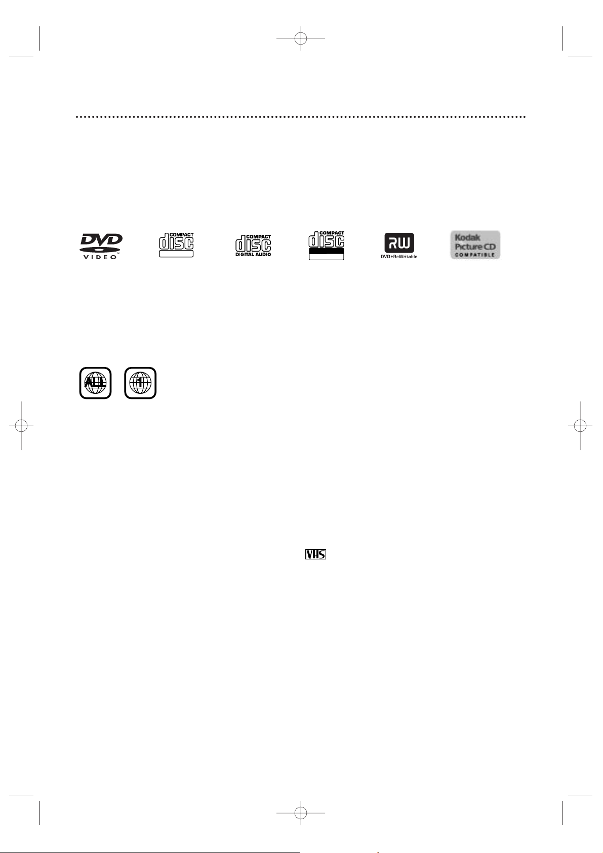
Playable Discs
The DVD Player will play Digital Video Discs (DVDs);Audio Compact Discs (CDs); Video CDs; finalized Digital
Video Discs Rewritable (DVD+RW);and finalized Compact Discs Rewritable (CD-RW) and Compact Discs
Recordable (CD-R),including Picture CDs.
To play a DVD,make sure it meets the requirements for Region Codes and Color Systems as described below.
Discs that have the following logos will play on the DVD Player. Other Disc types are not guaranteed to play.
DVD Video CD Audio CD CD-RW/CD-R DVD+RW Picture CD
MX5100VR.qxd 6/04/2004 3:37 PM Page 6
DIGITAL VIDEO
Recordable
ReWritable
Page 7

Hookups 7
Determining the best possible connection...
Your hookup will be determined by your existing equipment,especially your TV.These guidelines describe which
options have the best picture (video) and sound (audio) quality.You will not use all the jacks on the System.
If your TV only has an RF-style jack, usually labelled Antenna In, RF In,or 75 ohm, use the
System’s TV ANTENNA OUT jack to connect to the TV. This hookup provides both audio and
video in a single cable. Set your TV to channel 3 or 4 - the output channel of the System.This
connection allows you to use both the DVD and VCR features.
Details are on page eight.
If your TV has Component Video In jacks (which could be labelled Y Cr Cb,Y Pr Pb,or YUV and may
be green,blue, and red),use the COMPONENT VIDEO OUT jacks (Y Pb/Cb Pr/Cr) for the best
picture quality.
If you use only this video connection,only the DVD picture will be available.To see DVD features on
the TV, set the TV to its Component Video In channel.
Details are on page 12.
If your TV has an S-Video In jack (which may be labelled Y/C or S-VHS), use the S-VIDEO OUT jack
for excellent picture quality. If you use only this video connection, only the DVD picture will be
available.To see DVD features on the TV,set the TV to its S-Video In channel.
Details are on page 13.
If your TV has a single yellow Video In jack (which may be labelled CVBS, Composite,or baseband),
use the yellow VIDEO (DVD/VCR OUT) jack for good picture quality.This connection provides a
picture for both the DVD Player and the VCR. Set the TV to its Video In channel.
Details are on page 11.
If you have a Stereo with a Coaxial Digital Audio In jack, this provides the clearest sound for the
DVD Player.Connect the System’s DIGITAL AUDIO OUT COAXIAL jack to your Stereo.If you use
only this audio connection,only Disc sound (no VCR) will be available.
Details are on page 15.
If digital audio connections are not possible,connect the System’s red and white AUDIO (DVD/VCR
OUT) jacks to the Audio In jacks of your Stereo or TV. This provides sound for both the DVD
Player and the VCR.
Details are on pages 11-14.
Before you begin...
● Refer to the manuals of your TV,Cable Box, Stereo,or other devices as necessar y.Note the style of jacks
and connectors on the other equipment.Determine how to choose different Audio and Video In channels on
your other equipment so you can see and hear the System playing on the TV,Stereo,etc.
● Disconnect all equipment from the power outlets.Connect the equipment to the power outlets only after
you have finished hooking up everything.Never make or change connections with equipment connected to
the power outlet.
Remember...
● Set the TV to the correct Video In channel.Such channels may be called AUX or AUXILIARYIN,
AUDIO/VIDEO or A/V IN,EXT1 or External In, etc.These channels often are located near channel zero.See
your TV owner’s manual for details.If you do not see the DVD or VCR playback on the TV,go to the lowest
TV channel (01 or 02) and change channels downward until you see the DVD or VCR picture on the TV.Or,
if your TV has only a single Antenna In jack and you are using the RF coaxial cable (as described on page
eight),set the TV to channel 3 or 4.
To find the right Audio/Video In channel,turn on the System. Press DVD to put the System in DVD mode.
With no Disc in the Player, a large DVD logo will appear on the TV screen when you get the TV on the
correct Audio/Video In channel or channel 3 or 4.
● Set a separate Stereo (if applicable) to the correct channel or “source” mode.
● Depending on your connection,you may need to purchase additional cables or adaptors.
● To use the VCR features, you must include a connection with the supplied yellow video cable
and red/white audio cables or with the supplied RF coaxial cable.
Once you determine the best option,find your choice on pages 8-15. Follow the specific steps for
the hookup you choose.
MX5100VR.qxd 6/04/2004 3:37 PM Page 7
Page 8
8 Hookups (cont’d)
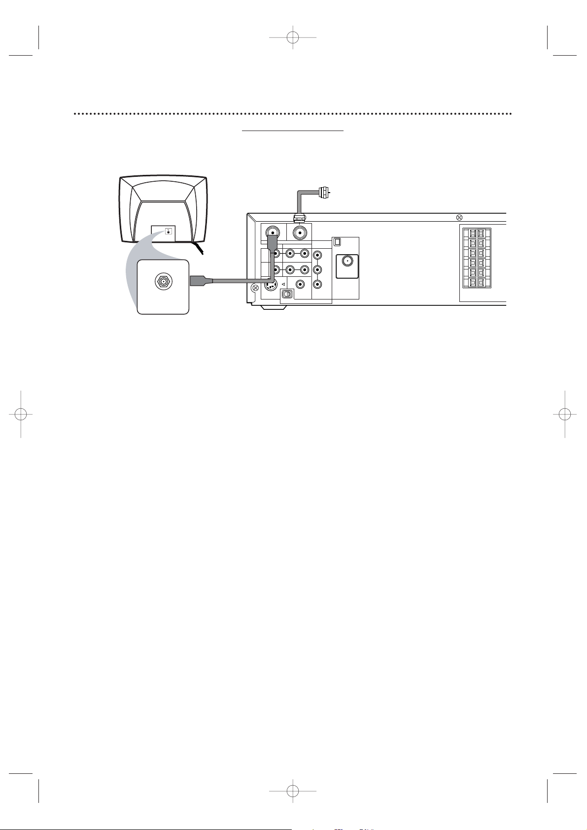
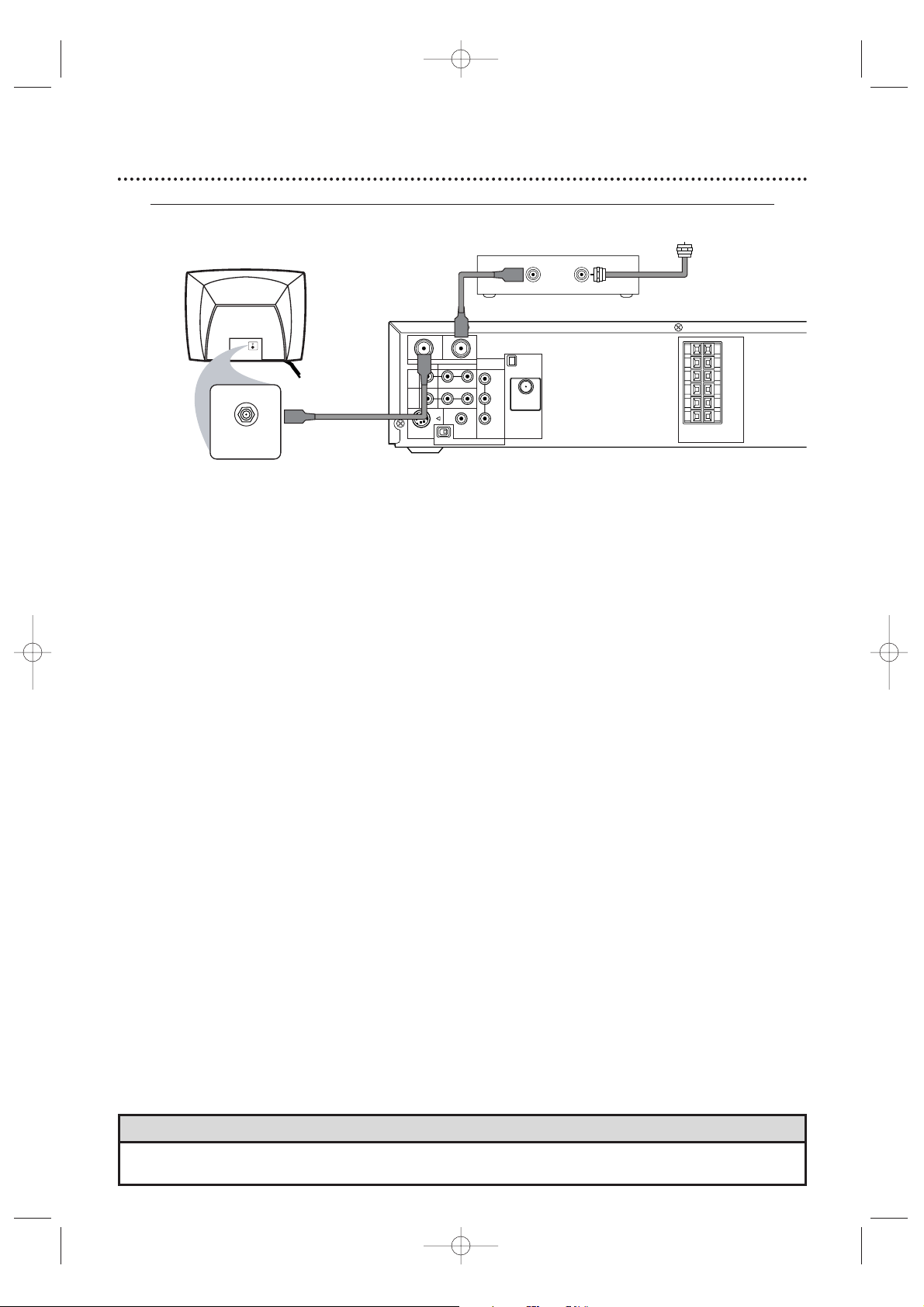
System to TV only
Simplest connection using only the supplied black RF coaxial cable
This connection will let you use the features of both the VCR and the DVD Player.
1
Disconnect the antenna or Cable TV signal from your TV and connect it to the TV
ANTENNA IN jack on the System.
2
Connect the supplied black RF coaxial cable to the System’s TV ANTENNA OUT jack
and to the Antenna In jack on the TV. The ANTENNAIN jack on the TV may be labelled TV IN,
RF IN,75Ω (ohm), or ANT. IN. See your TV owner’s manual for assistance.
3
Set the P/I PROGRESSIVE switch on the rear of the System to I (Interlace).
4
You are ready to connect the AM and FM antennas and the Speakers.See pages 16-17
to connect these items.
5
When all connections are complete, plug in the power cords of the TV and the System.
6
Set your TV to channel 3 or 4. The System’s output channel is 3 when you purchase it.So,set
your TV to channel 3 when the System is new.
If you cannot use channel 3 at your TV,you can change the System’s output channel to channel 4.To
do so,press the VCR button to put the System in VCR mode.The red VCR light will be on the front
of the System.Inser t a videotape and press PLAY
B to start playback.(You cannot change the
System’s output channel when you adjust the tracking manually. In this case, press STOP
C to stop
the playback once.Then, press PLAY B to star t playback again.)
During playback,press and hold the (VCR) PLAY B button on the front of the System
for three to five seconds.
Each time you do this,the System’s output channel switches between 3
and 4.Change your TV to channel 3 or 4 accordingly.
There is not a channel 3/4 switch on the System (as customary with most VCRs).
7
If you have not turned on the System already, go to page 19 to complete the VCR’s
First-Time Setup.This process sets up the TV channels and the language for the VCR menu.
MX5100VR.qxd 6/04/2004 3:37 PM Page 8
Antenna
or Cable TV
Signal
OUT
IN
AM
AUDIO
R L
DIGITAL
AUDIO OUT
COAXIAL
PROGRESSIVE
COMPONENT
VIDEO OUT
Y
Pb/Cb
Pr/Cr
ANTENNA 75Ω
ANTENNA 75Ω
FM
(75Ω)
TV ANTENNA
VIDEO
DVD/
VCR
OUT
VCR
IN
ANTENNA IN
RF IN
Back of TV
(example only)
RF coaxial cable
S-VIDEO
OUT
P I
FL
FR
C
SL
SR
W
SPEAKER (4Ω)
Page 9
Hookups (cont’d) 9
Connecting the Cable Bo
x/Satellite Receiver to the System and to a TV
This connection will let you use the features of both the VCR and the DVD Player.
• If your Cable Box/Satellite Receiver has Audio/Video Out jac ks,use audio/video cables to connect them to the
AUDIO and VIDEO (VCR IN) jacks on the System.You will not need the RF coaxial cable as described at step 2.
Helpful Hint
1
Connect a Cable TV or Satellite signal to the IN jack on the Cable Box/Satellite Receiver.
2
Use an RF coaxial cable to connect the OUT Jack on the Cable Box/Satellite Receiver to
the System’s TV ANTENNA IN jack.
3
Use a second RF coaxial cable (one is supplied) to connect the System’s TV ANTENNA
OUT jack to the TV’s Antenna In jack.
4
Set the P/I PROGRESSIVE switch on the rear of the System to I (Interlace).
5
You are ready to connect the AM and FM antennas and the Speakers.Go to pages 16-17 to
connect these items.
6
When all connections are complete,plug in the power cords of the TV, Cable Box/Satellite
Receiver, and the System.
7
Set your TV to channel 3. If you cannot use channel 3 at your TV,you can change the System’s output
channel to channel 4.See step 6 on page eight for details.
8
If you have not turned on the System already, go to page 19 to complete the VCR’s FirstTime Setup.
With this connection ...
● Select TV channels at the Cable Box/Satellite Receiver, not the System. To record or view TV channels:
1) Press VCR to put the System in VCR mode .The red VCR light will appear on the front of the System.
2) Press SKIP i /CH o or SKIP j /CH p to set the System to the Cable Box/Satellite Receiver
output channel (03 or 04).
3) Set the TV to the System’s output channel (03 or 04).
4) Select the channel you want to view/record at the Cable Box/Satellite Receiver.
● You may not view a channel other than the one you are recording.
● Program a timer recording for one channel at a time.Set your Cable Box/Satellite Receiver to the channel
you want to record. When you enter the channel you want to record in a timer recording,select channel 03
or 04 (the Cable Box/Satellite Receiver output channel).(This is step 8 on page 39.) Leave the Cable
Box/Satellite Receiver on for a timer recording.
MX5100VR.qxd 6/04/2004 3:37 PM Page 9
Back of TV
(example only)
RF coaxial cable
OUT IN
Antenna or
Cable TV signal
OUT
IN
AM
R L
P I
AUDIO
DIGITAL
AUDIO OUT
COAXIAL
PROGRESSIVE
COMPONENT
VIDEO OUT
Y
Pb/Cb
Pr/Cr
ANTENNA 75Ω
ANTENNA 75Ω
FM
(75Ω)
SPEAKER (4Ω)
ANTENNA IN
RF IN
RF coaxial cable
DVD/
VCR
OUT
VCR
IN
S-VIDEO
TV ANTENNA
VIDEO
OUT
FL
FR
C
SL
SR
W
Page 10
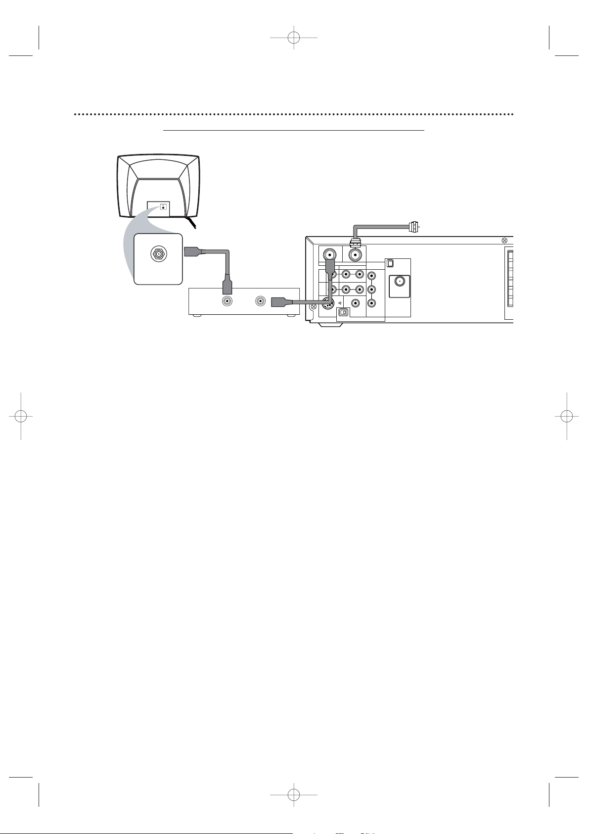
10 Hookups (cont’d)
1
Connect the Cable TV or Satellite signal to the System’s TV ANTENNA IN jack.
2
Connect an RF coaxial cable to the System’s TV ANTENNA OUT jack and to the IN
jack on the Cable Box/Satellite Receiver.
3
Connect another RF coaxial cable to the OUT jack on the Cable Box/Satellite Receiver
and to the ANTENNA IN jack on the TV.
4
Set the P/I PROGRESSIVE switch on the rear of the System to I (Interlace).
5
You are ready to connect the AM and FM antennas and the Speakers.Go to pages 16-17
to connect these items.
6
When all connections are complete, plug in the power cords of all equipment.Set the
Cable Box/Satellite Receiver to channel 3 (the System’s default output channel). Set the
TV to the Cable Box/Satellite Receiver’s output channel (03 or 04).
7
If you have not turned on the System already, go to page 19 to complete the VCR’s
First-Time Setup.This process sets up the TV channels and the language for the VCR menu.
To watch one channel while recording another ...
1) Put the Cable Box/Satellite Receiver on channel 3 (the System’s default output channel). (To change it to
4,press and hold (VCR) PLAY
B on the front of the System for 3-5 seconds during tape playback. Details
are on page eight.) Set the TV to the Cable Box/Satellite Receiver output channel (03 or 04).
2) Press VCR to put the System in VCR mode .The red VCR light will appear on the front of the System.
3) Press VCR/TV on the remote to choose VCR position.
4) Press SKIP i /CH o or SKIP j /CH p to select the channel you want to record at the System.
Press REC
I or RECORD I to start the recording.
5) Press VCR/TV on the remote once to put the System in TV position.
6) Select the channel you want to watch at the Cable Box/Satellite Receiver.
System to Cable Bo
x/Satellite Receiver and TV
This connection will let you use the features of both the VCR and the DVD Player.
P
MX5100VR.qxd 6/04/2004 3:37 PM Page 10
Cable TV
or Satellite Signal
ANTENNA IN
RF IN
Back of TV
(example only)
RF coaxial cable
OUT IN
Cable Box/Satellite Receiver
(example only)
RF coaxial cable
OUT
DVD/
VCR
OUT
VCR
IN
S-VIDEO
VIDEO
OUT
IN
TV ANTENNA
R L
P I
AUDIO
DIGITAL
AUDIO OUT
COAXIAL
PROGRESSIVE
COMPONENT
VIDEO OUT
Y
Pb/Cb
Pr/Cr
AM
ANTENNA 75Ω
ANTENNA 75Ω
FM
(75Ω)
S
Page 11
Hookups (cont’d) 11
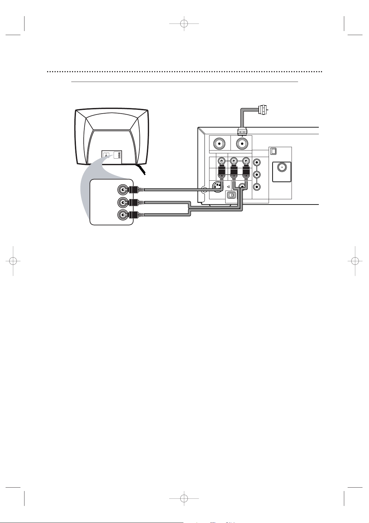
1
Connect the antenna or Cable TV signal to the System’s TV ANTENNA IN jack.
2
Connect the red and white audio cables (supplied) to the red and white AUDIO
(DVD/VCR OUT) jacks on the System and to the red and white AUDIO IN jacks on the
TV. Match the cable colors to the jack colors. If the TV has a single AUDIO IN jack,use the white
audio cable to connect the System’s white AUDIO L (left) (DVD/VCR OUT) jack to the TV’s AUDIO
IN jack.You will not use the red cable.
3
Connect the yellow video cable (supplied) to the System’s yellow VIDEO (DVD/VCR
OUT) jack and to the VIDEO IN jack on the TV. The VIDEO IN jack on the TV is usually
yellow and may be labelled CVBS,Composite , or Baseband video.
4
Set the P/I PROGRESSIVE switch on the rear of the System to I (Interlace).
5
You are ready to connect the AM and FM antennas and the Speakers.Go to pages 16-17
to connect these items.
6
When all connections are complete, connect the power cords of the TV and the System
to a power outlet.Turn on the TV and set it to the Audio/Video In channel. To find the
right Audio/Video In channel, turn on the System. Press DVD to put the System in DVD mode.With
no Disc in the Player, a large DVD logo will appear on the TV screen when you get the TV on the
correct Audio/Video In channel. Go to your lowest TV channel (01 or 02), then change channels
down until you see the DVD logo.
7
If you have not turned on the System already, go to page 19 to complete the VCR’s
First-Time Setup.This process sets up the TV channels and the language for the VCR menu.
Connecting the System to a TV that has
Audio and Video In jacks
This connection will let you use the features of both the VCR and the DVD Player.
MX5100VR.qxd 6/04/2004 3:37 PM Page 11
Antenna
or Cable TV
Y
Pb/Cb
Pr/Cr
FM
(75Ω)
Signal
AM
ANTENNA 75Ω
ANTENNA 75Ω
VIDEO IN
RIGHT AUDIO IN
LEFT AUDIO IN
VIDEO IN
RIGHT AUDIO IN
LEFT AUDIO IN
Back of TV
(example only)
red/white
audio
cables
yellow
video
cable
OUT
DVD/
VCR
OUT
VCR
IN
S-VIDEO
TV ANTENNA
VIDEO
OUT
P I
IN
AUDIO
R L
DIGITAL
AUDIO OUT
COAXIAL
PROGRESSIVE
COMPONENT
VIDEO OUT
Page 12
12 Hookups (cont’d)
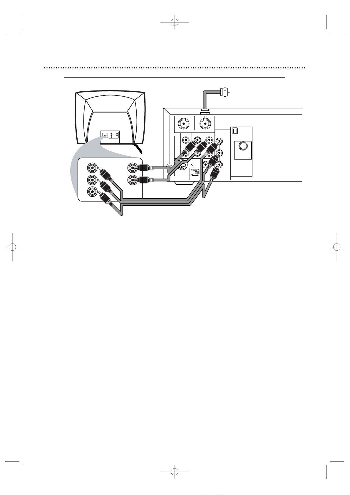
Connecting the System to a TV that has Component
Video In jacks
1
Connect the antenna or Cable TV signal to the System’s TV ANTENNA IN jack.
2
Connect the supplied red/white audio cables to the System’s red/white AUDIO
(DVD/VCR OUT) jacks and to the TV’s AUDIO IN jacks. Match cable colors to jack colors.
3
Connect component video cable to the System’s COMPONENT VIDEO OUT (Y Pb/Cb
Pr/Cr) jacks and to the COMPONENT VIDEO IN jacks on the TV. Component Video In
jacks on the TV are usually red,blue, and green.
The Component Video connection only supplies video (picture) for the DVD Player of the System.To use the
VCR or see TV channels, you must connect the RF coaxial cable or the yellow video cable.To connect the RF
coaxial cable, see step 2 on page eight.To connect the yellow video cable, see step 3 on page 11.If you are
using the RF coaxial cable for VCR playbac k, choose channel 3 or 4 at the TV.If you are using the yellow
video cable for VCR playbac k, choose the Video In channel at your TV.
4
Set the P/I PROGRESSIVE switch on the rear of the System to I (Interlace).
Or, if your TV has Progressive Scan, set the P/I PROGRESSIVE switch to P (Progressive).
5
You are ready to connect the AM and FM antennas and the Speakers.Go to pages 16-17
to connect these items.
6
When all connections are complete, connect the power cords of the System and TV to
a power outlet.Turn on the TV and set it to the Component Video In channel for DVD
Player features.To help you find the Component Video In channel, turn on the System. Press DVD
to put the System in DVD mode.With no Disc in the Player, a large DVD logo will appear on the TV
screen when you get the TV on the correct Component Video In channel. Go to your lowest TV
channel (01 or 02) and change channels down until you see the DVD logo on the TV screen.
7
If you have not turned on the System already, go to page 19 to complete the VCR’s
First-Time Setup.This process sets up the TV channels and the language for the VCR menu.
8
Set DOLBY DIGITAL to OFF in the DVD Player’s Setup menu.Details are on page 72.
Playing a DVD when the settings are wrong could distort the sound or damage the speakers.
MX5100VR.qxd 6/04/2004 3:37 PM Page 12
Antenna
or Cable TV
Signal
Y
Pb/Cb
Pr/Cr
Back of TV
(example only)
Y
RIGHT AUDIO IN
LEFT AUDIO IN
Cb/B-Y
Cr/R-Y
RIGHT AUDIO IN
LEFT AUDIO IN
red/white
Audio
Cables
OUT
DVD/
VCR
OUT
VCR
IN
S-VIDEO
TV ANTENNA
VIDEO
OUT
P I
IN
R L
COMPONENT
VIDEO OUT
AUDIO
DIGITAL
AUDIO OUT
COAXIAL
PROGRESSIVE
Component
Video
Cables
Y
Pb/Cb
Pr/Cr
FM
(75Ω)
AM
ANTENNA 75Ω
ANTENNA 75Ω
Page 13
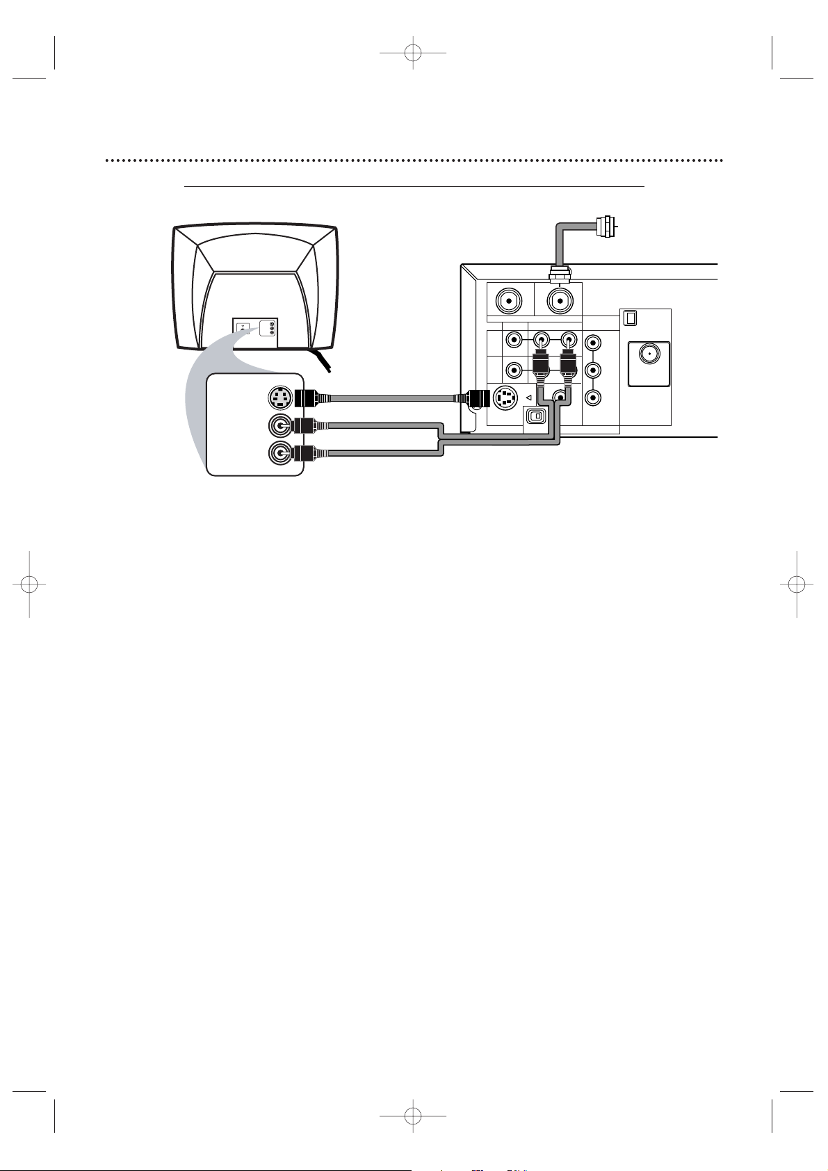
Hookups (cont’d) 13
Connecting the System to a TV that has an S-Video In jack
1
Connect the antenna or Cable TV signal to the System’s TV ANTENNA IN jack.
2
Connect the supplied red/white audio cables to the System’s red/white AUDIO
(DVD/VCR OUT) jacks and to the TV’s AUDIO IN jacks. Match cable colors to jack colors.
3
Connect an S-Video cable to the System’s S-VIDEO OUT jack and to the S-VIDEO IN
jack on the TV. S-Video only supplies a DVD picture. To use the VCR or view TV channels , connect the RF
coaxial cable or the yellow video cable. To use the RF coaxial cable,see step 2 on page eight. To use the
yellow video cable,see step 3 on page 11. If you are using the RF coaxial cable for VCR playbac k, choose
channel 3 or 4 at the TV.If you are using the yellow video cable, choose the Video In channel at your TV.
4
Set the P/I PROGRESSIVE switch on the rear of the System to I (Interlace).
5
You are ready to connect the AM and FM antennas and the Speakers.Go to pages 16-17
to connect these items.
6
When all connections are complete, connect the power cords of the System and TV to
a power outlet.Turn on the TV and set it to the S-Video In channel for DVD Player
features.To help you find the right S-Video In channel,turn on the System. Press DVD to put the
System in DVD mode.With no Disc in the Player, a large DVD logo will appear on the TV screen
when you get the TV on the S-Video In channel.Go to your lowest TV channel (01 or 02) and
change channels down until you see the DVD logo on the TV screen.
7
If you have not turned on the System already, go to page 19 to complete the VCR’s
First-Time Setup.This process sets up the TV channels and the language for the VCR menu.
8
Set DOLBY DIGITAL to OFF in the DVD Player’s Setup menu.Details are on page 72.
Playing a DVD when the settings are wrong could distort the sound or damage the speakers.
MX5100VR.qxd 6/04/2004 3:37 PM Page 13
S-VIDEO IN
RIGHT AUDIO IN
LEFT AUDIO IN
S-VIDEO IN
RIGHT AUDIO IN
LEFT AUDIO IN
Back of TV
(example only)
S-Video Cable
red/white
Audio Cables
OUT
DVD/
VCR
OUT
VCR
IN
S-VIDEO
TV ANTENNA
VIDEO
OUT
P I
IN
AUDIO
R L
DIGITAL
AUDIO OUT
COAXIAL
PROGRESSIVE
COMPONENT
VIDEO OUT
Y
Pb/Cb
Pr/Cr
Antenna
or Cable TV
Signal
AM
ANTENNA 75Ω
ANTENNA 75Ω
FM
(75Ω)
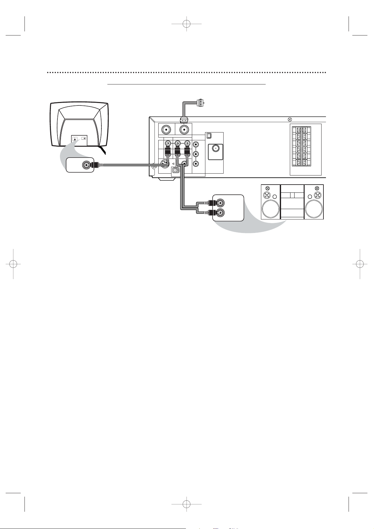
Page 14
14 Hookups (cont’d)
Connecting the System to a TV and a Stereo
1
Connect the antenna or Cable TV signal to the System’s TV ANTENNA IN jack.
2
Connect the red/white audio cables to the System’s red/white AUDIO (DVD/VCR OUT)
jacks and to the Stereo’s red/white AUDIO IN jacks. Match cable colors to jack colors.
3
Connect the yellow video cable to the System’s VIDEO (DVD/VCR OUT) jack and to
the TV’ s VIDEO IN jack. To use Component Video cable or S-Video cable instead for the DVD
Player, see pages 12-13. You still need the yellow video cable or RF coaxial cable for VCR features.
4
Set the P/I PROGRESSIVE switch on the rear of the System to I (Interlace).
5
You are ready to connect the AM and FM antennas and the Speakers.Go to pages 16-17
to connect these items.
6
After everything is connected,connect the power cords of the System,TV, and Stereo
to a power outlet.Turn on the TV and set it to the Video In channel. Go to your TV’s
lowest channel (01 or 02) and change channels downward until you find the Video In channel.
To find the right Video In channel at the TV,turn on the System. Press DVD to put the System in
DVD mode.With no Disc in the Player, a large DVD logo will appear on the TV screen when you get
the TV on the correct Video In channel.
7
If you have not turned on the System already, go to page 19 to complete the VCR’s
First-Time Setup.This process sets up the TV channels and the language for the VCR menu.
8
Set DOLBY DIGITAL to OFF in the DVD Player’s Setup menu.Details are on page 72.
Playing a DVD when the settings are wrong could distort the sound or damage the speakers.
MX5100VR.qxd 6/04/2004 3:37 PM Page 14
VIDEO IN
VIDEO IN
Back of TV
(example only)
yellow Video Cable
OUT
DVD/
VCR
OUT
VCR
IN
S-VIDEO
TV ANTENNA
VIDEO
OUT
P I
IN
AUDIO
R L
DIGITAL
AUDIO OUT
COAXIAL
PROGRESSIVE
COMPONENT
VIDEO OUT
Y
Pb/Cb
Pr/Cr
red/white
Audio Cables
Antenna
or Cable TV
Signal
AM
ANTENNA 75Ω
ANTENNA 75Ω
FM
(75Ω)
LEFT AUDIO IN
RIGHT AUDIO IN
SPEAKER (4Ω)
Stereo
(example only)
FL
FR
C
SL
SR
W
Page 15
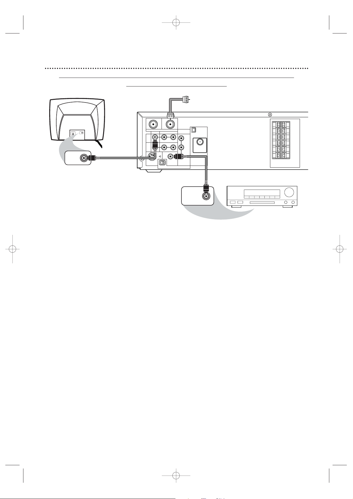
Hookups (cont’d) 15
Connecting the System to a TV and a Dolby Digital-compatible Stereo
Use Digital Audio connections
1
Connect the antenna or Cable TV signal to the System’s TV ANTENNA IN jack.
2
Connect a coaxial digital audio cable (not supplied) to the System’s DIGITAL AUDIO
OUT COAXIAL jack and to the COAXIAL DIGITAL AUDIO IN jack on the Stereo.
This digital audio connection only provides DVD sound.To use the VCR or view TV channels, connect the RF
coaxial cable or the red/white audio cables. To connect the RF coaxial cable,see step 2 on page eight. To
connect the audio cables, see step 2 on page 11.
3
Connect the yellow video cable to the System’s yellow VIDEO (DVD/VCR OUT) jack
and to the TV’s VIDEO IN jack. To use component video cable or S-Video cable instead for the
DVD Player,see pages 12-13.You need the yellow video cable or RF coaxial cable for VCR features.
4
Set the P/I PROGRESSIVE switch on the rear of the System to I (Interlace).
5
You are ready to connect the AM and FM antennas and the Speakers.Go to pages 16-17
to connect these items.
6
After everything is connected,plug in the power cords of the Stereo,TV, and System.
Turn on the Stereo and select its Auxiliary IN channel.Turn on the TV and set it to the
Video In channel.To find the right Video In channel on the TV, turn on the System.Press DVD to
put the System in DVD mode.With no Disc in the Player, a large DVD logo will appear on the TV
screen when you get the TV on the correct Video In channel. Go to your TV’s lowest channel (01 or
02) and change channels downward until you see the DVD logo.
7
If you have not turned on the System already, go to page 19 to complete the VCR’s
First-Time Setup.
This process sets up the TV channels and the language for the VCR menu.
Remember...
Some DVDs are recorded in 5.1 channel Dolby Digital Surround.Select 5.1 channel Dolby Digital Surround
Sound in the DVD Disc menu.If Dolby Digital Surround is not recorded on the Disc,you will not have
surround sound.
If your Stereo is Dolby-Digital compatible,set DOLBYDIGITAL to ON at the DVD Player.Details are on page 72.
Otherwise,set DOLBY DIGITAL to OFF. Incorrect settings could distort the sound or damage the speakers.
MX5100VR.qxd 6/04/2004 3:37 PM Page 15
Antenna or
Cable TV Signal
VIDEO IN
VIDEO IN
Back of TV
(example only)
yellow Video Cable
OUT
DVD/
VCR
OUT
VCR
IN
S-VIDEO
TV ANTENNA
VIDEO
OUT
IN
R L
P I
AUDIO
DIGITAL
AUDIO OUT
COAXIAL
PROGRESSIVE
COMPONENT
VIDEO OUT
Y
Pb/Cb
ANTENNA 75Ω
FM
Pr/Cr
(75Ω)
Coaxial Digital
Audio Cable
AM
ANTENNA 75Ω
Stereo
(example only)
FL
FR
C
SL
SR
W
SPEAKER (4Ω)
COAXIAL DIGITAL
AUDIO IN
Page 16
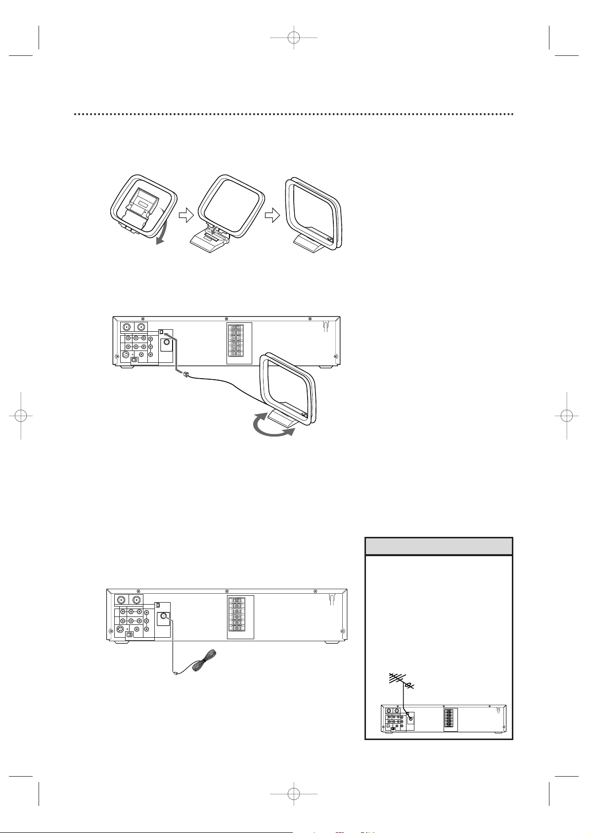
16 Antenna Connections
AM Antenna
1
Fix the antenna holder as shown.
2
Connect the supplied AM antenna to the AM jack,
then position it to receive the clearest sound.
FM Antenna
1
Connect the supplied FM antenna to the FM jack.
Extend the FM antenna wire and fix its end to the
wall.
• Do not place the AM antenna on
the System.Keep it as far as
possible from the System and the
speaker wires.Keep it away from
the AC power cords of the System
and other equipment.
•For better FM reception,connect
an outdoor FM antenna (not
supplied) to the ANTENNA 75
ohm jack.
Helpful Hints
MX5100VR.qxd 6/04/2004 3:37 PM Page 16
OUT
IN
AM
COMPONENT
TV ANTENNA
VIDEO OUT
VIDEO
AUDIO
R L
DVD/
VCR
OUT
VCR
IN
DIGITAL
S-VIDEO
AUDIO OUT
COAXIAL
OUT
PROGRESSIVE
P I
ANTENNA 75Ω
Y
Pb/Cb
ANTENNA 75Ω
FM
Pr/Cr
(75Ω)
SPEAKER (4Ω)
OUT
IN
TV ANTENNA
VIDEO
R L
DVD/
VCR
OUT
VCR
IN
S-VIDEO
OUT
P I
AUDIO
DIGITAL
AUDIO OUT
COAXIAL
PROGRESSIVE
AM
COMPONENT
VIDEO OUT
ANTENNA 75Ω
Y
Pb/Cb
ANTENNA 75Ω
FM
Pr/Cr
(75Ω)
SPEAKER (4Ω)
FL
FR
C
SL
SR
W
FL
FR
C
SL
SR
W
OUT
IN
AM
COMPONENT
TV ANTENNA
VIDEO OUT
VIDEO
AUDIO
R L
DVD/
ANTENNA 75Ω
VCR
Y
OUT
VCR
Pb/Cb
IN
ANTENNA 75Ω
FM
Pr/Cr
(75Ω)
DIGITAL
S-VIDEO
AUDIO OUT
COAXIAL
OUT
PROGRESSIVE
P I
FL
FR
C
SL
SR
W
SPEAKER (4Ω)
Page 17
Speaker Setup 17
VIDEO
TV ANTENNA
AUDIO
R L
PROGRESSIVE
OUT
IN
ANTENNA 75Ω
ANTENNA 75Ω
Y
Pb/Cb
Pr/Cr
FM
(75Ω)
DIGITAL
AUDIO OUT
COAXIAL
S-VIDEO
OUT
VCR
IN
DVD/
VCR
OUT
COMPONENT
VIDEO OUT
AM
FL
FR
C
SL
SR
W
SPEAKER (4Ω)
P I
Center Speaker
Subwoofer
Front
Speaker
(left)
Rear Speaker
(left surround)
Rear Speaker
(right surround)
Front
Speaker
(right)
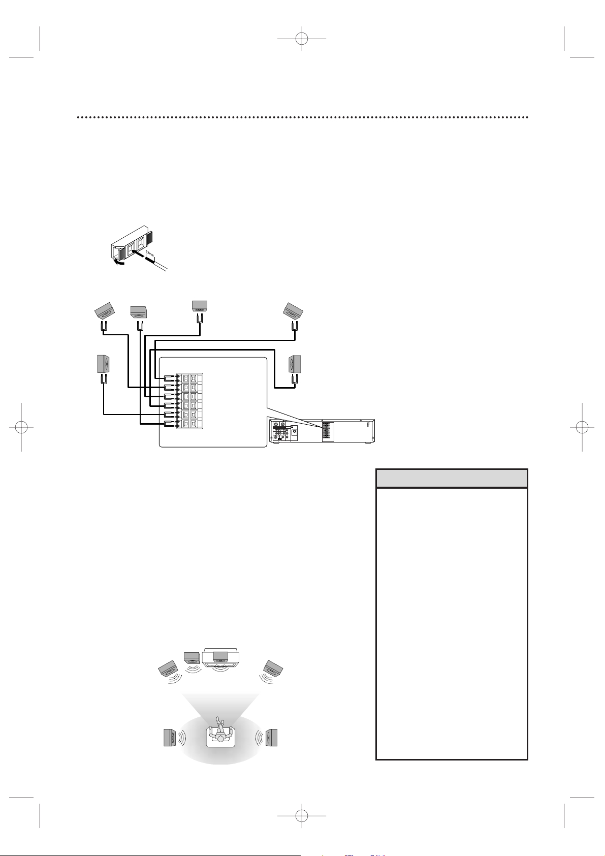
FL (Front Left - white)
FR (Front Right - red)
C (Center - green)
SL (Surround/Rear Left - blue)
SR (Surround/Rear Right - grey)
W (Subwoofer - purple)
Connecting the speaker wires to the speaker jacks
1
Connect the supplied speakers using the supplied speaker
wires.Match the colors of the wires to the colors on the
jacks.
Hold down the jack tab while inserting the stripped
portion of the speaker wire into the jack.Then, release
the tab.Make sure you do not insert the wire too far. None
of the rubber-coated wire should be clamped by the jack tab.
Setting up Surround Sound
Connect all the speakers and set up the System properly in order to
enjoy the Home Cinema experience.
1
Place the FRONT Left and Right speakers at equal distances
from the TV and at a 45-degree angle from the listening
position.
2
Place the CENTER speaker above or below the TV to localize
the sound.
3
Place the REAR (Surround) speakers at normal listening ear
level,facing each other or mounted on the wall. Use the
supplied mounting brackets to mount speakers to the wall.
4
Place the Subwoofer on the floor, near the TV.
VIEWING AREA
Center Speaker
Subwoofer
Front
Speaker
(left)
Rear Speaker
(left surround)
Rear Speaker
(right surround)
Front
Speaker
(right)
TV
• Connect the speaker wires
correctly.Improper connections
may short circuit the System.
•For optimal sound,use the
supplied speakers.
• Do not connect more than one
speaker to any pair of speaker
jacks on the System.
• Do not connect speakers with an
impedance lower than 6 ohms.
• Sit in your usual listening position
to set up the speaker balance.
Details are on pages 52-53.
•To avoid magnetic interference, do
not place the FRONT speakers too
close to your TV.
• Placing the REAR (Surround)
speakers farther from the listening
position than the FRONT and
CENTER speakers will weaken the
Surround Sound effect.
• Secure all speakers to prevent
accidents and improve sound
quality.Use the supplied mounting
brackets to mount speaker s to a
wall.Details are on page 18.
Helpful Hints
MX5100VR.qxd 6/04/2004 3:37 PM Page 17
Page 18
18 Speaker Setup (cont’d), Remote Control Setup
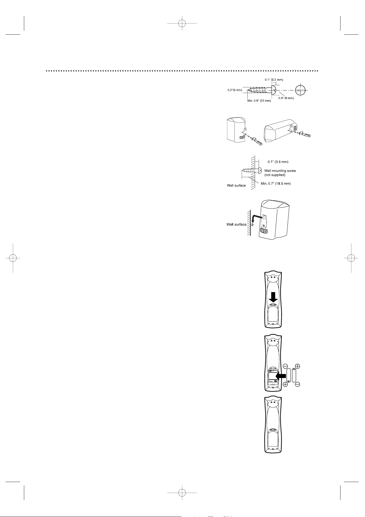
Putting Batteries in the Remote Control
1
Remove the battery compartment lid on the bottom of
the remote control by pressing the tab,then lifting the lid.
2
Place two AA batteries inside the battery
compartment with their + and – ends aligned as indicated.
3
Replace the battery compartment lid.
Using the Remote Control
● Point the remote control at the System’s remote sensor (marked
IR,see page 24) when using the remote to operate the System. Do
not point the remote at the TV.
● Do not put objects between the remote and the System.
Recycling Guidelines/Battery Safety
●
Your new product and its packaging contain materials that can be
recycled and reused.Specialized companies can recycle your product
to increase the amount that needs to be properly disposed.Your
product uses batteries that should not be thrown away when depleted
but should be disposed of as small chemical waste. Please find out
about the local regulations on disposal of your old product,batteries,
and packaging whenever you replace existing equipment.
● Battery Usage CAUTION - To prevent battery leakage that may
result in bodily injury,property damage , or damage to the unit:
Install ALL batteries correctly,with the + and - markings on the
battery aligned as indicated on the unit;
Do not mix batteries,for example , old with new or carbon with
alkaline;and
Remove batteries when the unit will not be used for a long time.
1
2
3
Speaker setup
You can hang the front,center and rear (Surround) speakers on a
wall.Each speaker needs one screw (not supplied) for mounting.
Use the type and size of screw as shown at right.
1
Attach a supplied bracket to the back of each speaker
with one of the supplied screws.
2
Drive a screw into the wall.Make sure the screw and the
wall can support 11 lbs. (5 Kg.) Drive the screw until the
screw head extends about 0.1” (3.5 mm) from the wall.
3
Hook the slot in the speaker’s bracket onto the wallmounted screw. Tuck the extra speaker wire into the
recessed area behind the speaker.
Caution
• Check the stability of the ceiling or wall. Philips is not liable for
accidents caused by insufficient stability of the ceiling or wall or for
improper mounting.
• The speaker may fall due to unstable mounting.
• If you need assistance, contact Philips.
• Do not modify or change the fittings of the supplied speakers,
mounting brackets,and screws.Use these brackets to mount the
supplied speakers only. Do not load anything else on these fittings.
• Do not step on or hang from the speakers.Pay special attention to
small children to ensure their safety.
1
2
3
MX5100VR.qxd 6/04/2004 3:37 PM Page 18
Page 19
First-time Setup 19
Before turning on your System,make sure batteries are in the
remote control and the TV and System are connected correctly.
You cannot program TV channels at the System if you are using a
Cable Box or a Satellite Receiver. You will change channels at the
Cable Box/Satellite Receiver.
1
Turn on the TV. Set it to channel 3 or 4 or its
AUDIO/VIDEO IN channel, depending on how you
connected the System to a TV.
2
Press STANDBY-ON
yy
to turn on the System, then
press VCR.The red VCR light and the red STANDBY-ON
light will appear on the front of the System.This display will
appear.
These menus may not appear if you have already
turned on the System (to find the Audio/Video In
channel of the TV, for example).Follow the steps on
page 28 to set up TV channels and page 32 to select a
language for the VCR menus.
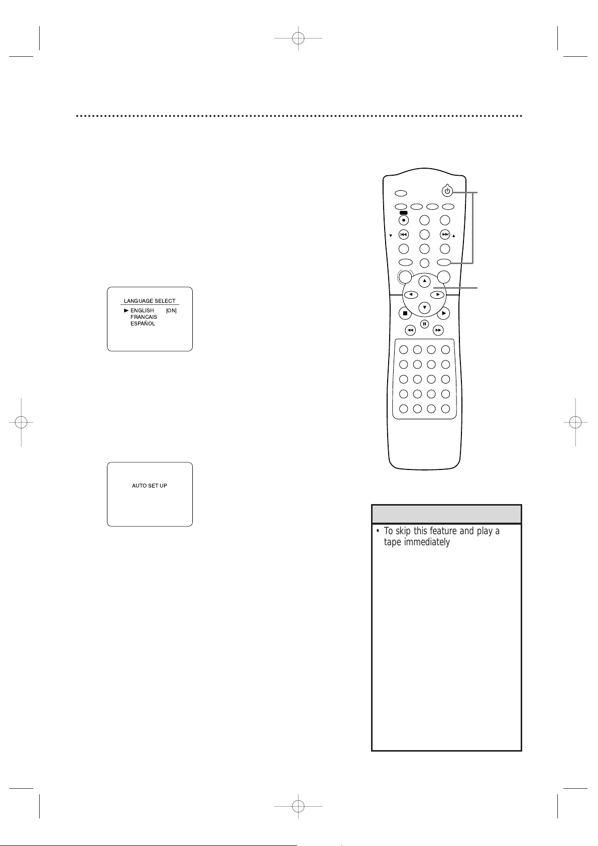
3
Press o or p to select English, French,or Spanish as
the language for VCR on-screen displays and menus.
Then, press B.
4
Press B to begin channel programming.AUTO SETUP
will flash on the TV screen during the channel search.The
System will memorize all available channels.When channel
programming is complete,the lowest available channel will
appear on the TV.These channels will be available when you
want to watch TV while the System is in VCR mode.To put
the System in VCR mode, press VCR so the red VCR light
appears.Use the SKIP i /CH o and SKIP j /CH p
buttons to select memorized channels. To select nonmemorized channels,use the Number buttons.
•To skip this feature and play a
tape immediately,inser t a tape
with its record tab removed.
•To skip step 3, press DISC/MENU.
VCR menus and displays will be in
English.
• If you try to program channels
when there is no antenna or Cable
TV signal connected to the
System’s TV ANTENNA IN jack,
programming will stop. AUTO SET
UP will stop flashing.Connect an
antenna or Cable TV signal to the
System’s TV ANTENNA IN jack
and press B again.
• Repeat this process if the power
fails for more than 30 seconds.
•To stop the Channel Setup while
AUTO SET UP is flashing, press
DISC/MENU.
Helpful Hints
STANDBY-ON
TIMER SET
VCR/TV
SEARCH MODE
REPEAT
TUNER
3
456
789
SLOW
0
+10
2
1
VCRDVD
CLEAR
DISPLAY
SETUP/
PROG
TITLE RETURNMODE/SPEED
C-RESET
AUDIO/
BAND
ANGLE
SUBTITLE
ZOOM
DISC
MENU
OK
PAUSE
REW FF
PLAYSTOP
SKIP/
CH
SKIP/
CH
REPEAT
SOUNDSURROUND
+–
VOLUME
REC
A-B
PHILIPS
1
Turn on the TV.
2
3-4
MX5100VR.qxd 6/04/2004 3:37 PM Page 19
B
Page 20
20 Video Cassette Playback
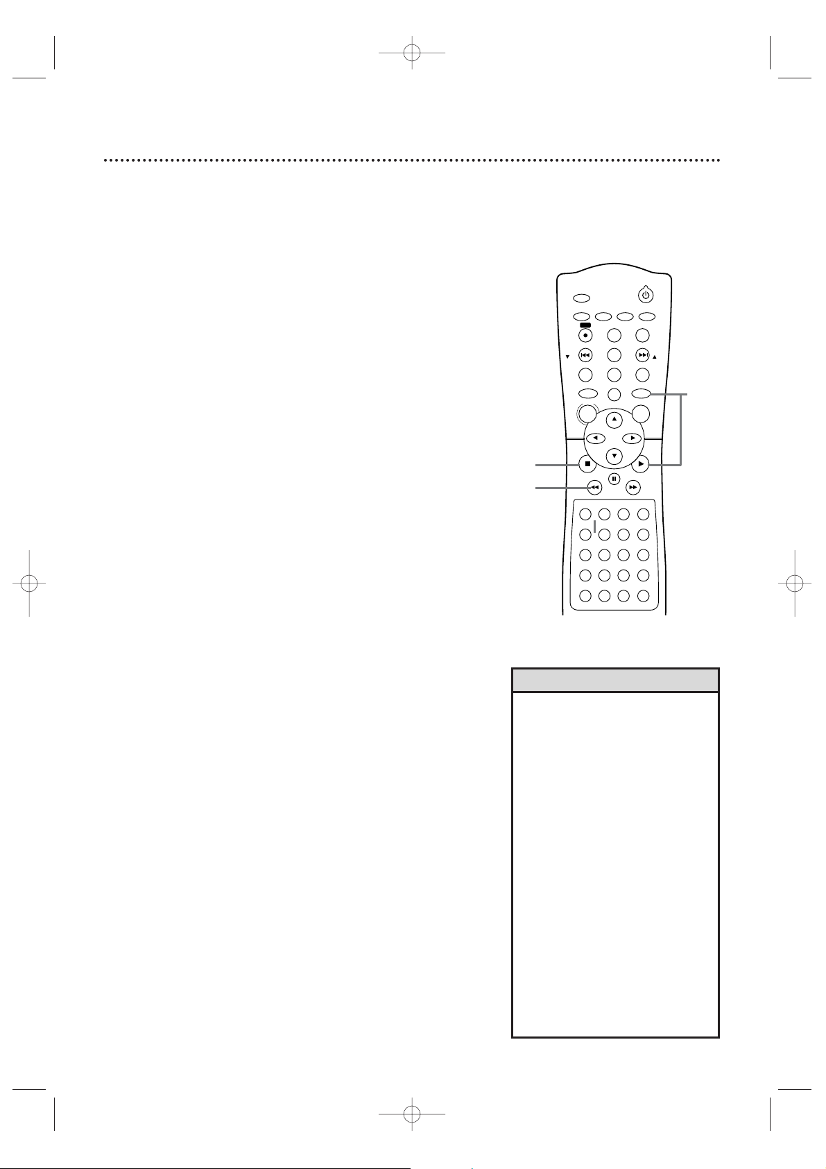
Read and follow the steps below to play a tape.
1
Turn on the TV. Set it to channel 3 or 4 or its
AUDIO/VIDEO IN channel.This depends on how you
connected the System to a TV. Details are on pages 8-11.
2
With the System’s power off,insert a tape in the
cassette compartment. The STANDBY-ON and VCR lights
will appear on the front of the System.If the tape’s record tab
has been removed,playback will start automatically.
Or, if the System’s power is already on,press VCR to put the
System in VCR mode.The red VCR light will appear on the
front of the System.
3
If play does not start automatically, press VCR, then
press PLAY B.
4
Press STOP C to stop playback.
5
Press REW h to rewind the tape.
6
After the tape stops,press STOP/EJECT C A on the
front of the System to remove the tape.
• Other tape playback features are
on pages 42-46.
• If AUTO REPEAT is ON,playback
will begin when you insert a tape ,
even when the record tab is intact.
Details are on page 42.
•You must connect the System to a
TV using the RF coaxial cable or
the audio/video cables in order to
use the VCR features.These
hookups are explained on pages
eight and 11.
•You cannot use the VCR when the
System is in Tuner mode . If you fast
forward,rewind, or eject a videotape,
you may hear noise through the
speakers or some displays may be
incorrect.
•You cannot use the Tuner when the
System is in VCR mode. Make sure
you stop tape play before putting
the System in Tuner mode .
Helpful Hints
STANDBY-ON
TIMER SET
VCR/TV
SEARCH MODE
REPEAT
TUNER
3
456
789
SLOW
0
+10
2
1
VCRDVD
CLEAR
DISPLAY
SETUP/
PROG
TITLE RETURNMODE/SPEED
C-RESET
AUDIO/
BAND
ANGLE
SUBTITLE
ZOOM
DISC
MENU
OK
PAUSE
REW FF
PLAYSTOP
SKIP/
CH
SKIP/
CH
REPEAT
SOUNDSURROUND
+–
VOLUME
REC
A-B
1
Turn on the TV.
2
Insert a tape in the System.
3
6
Press STOP/EJECT C A on
the System.
4
5
MX5100VR.qxd 6/04/2004 3:37 PM Page 20
Page 21
Disc Playback 21
Before you begin,turn on the TV and set it to the correct Video In
channel.Details are on pages 7-15.
1
Press STANDBY-ON yyto turn on the System.
2
Press DVD so the red DVD light appears on the front
of the System.
3
Press OPEN/CLOSE A (to the right of the disc tray on the
front of the System) to open the Disc tray.
4
Place a Disc into the tray. If the DVD is recorded on only
one side, place the Disc in the tray with the label facing up and
the shiny side facing down.
Some DVDs are recorded on both sides.Make sure the label
of the side you want to play is facing up.
5
Press PLAY B. The tray will close and play will begin. If a
DVD menu appears instead,see page 54.With some Audio
CDs,play will not begin unless you press PLAY B.
You also can press OPEN/CLOSE A or press the tray toward
the System to close the tray.
6
Press STOP C to stop playback.
• An “X”may appear at the top
right corner of the TV screen when
you try a feature. Either the feature
is not available on the Disc, or the
System cannot access the feature
at this time. This does not indicate
a problem with the System.
• If a Disc is dirty or scratched, the
picture may appear distorted or
play may stop.Remove the Disc
and turn off the System.
Disconnect the power cord,then
reconnect it.Clean the Disc, then
turn on the System again and
reinsert the Disc . You may need to
repeat the System’s setup because
of the temporary power loss.
• When the DVD or CD light
appears on the display panel, the
Disc is loaded and ready to play.
• When you press OPEN/CLOSE
A
or PLAY B(DVD) on the front of
the System when the power is off,
the System will turn on in DVD
mode. Otherwise, the System will
turn on in the mode in which it
was turned off.
• Do not use the DVD Player
features when the System is in
Tuner mode . You may hear noises
through the speakers or the
displays may be incorrect.
Helpful Hints
Remember,the DVD Player of this
System will play only certain Discs .
See page six for details.
STANDBY-ON
TIMER SET
TUNER
VCRDVD
CLEAR
DISPLAY
SETUP/
PROG
TITLE RETURNMODE/SPEED
C-RESET
AUDIO/
BAND
ANGLE
SUBTITLE
ZOOM
DISC
MENU
OK
PAUSE
REW FF
PLAYSTOP
SKIP/
CH
SKIP/
CH
REC
5
3
Press OPEN/CLOSE A on
the front of the System.
4
Insert a Disc.
6
2
1
MX5100VR.qxd 6/04/2004 3:37 PM Page 21
Page 22
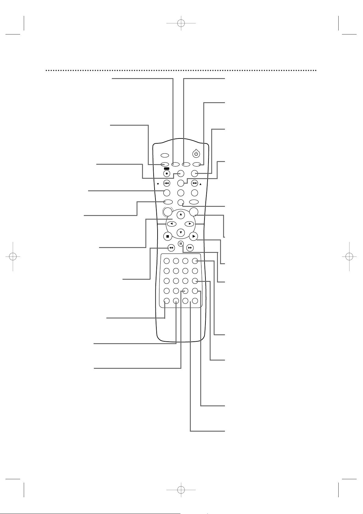
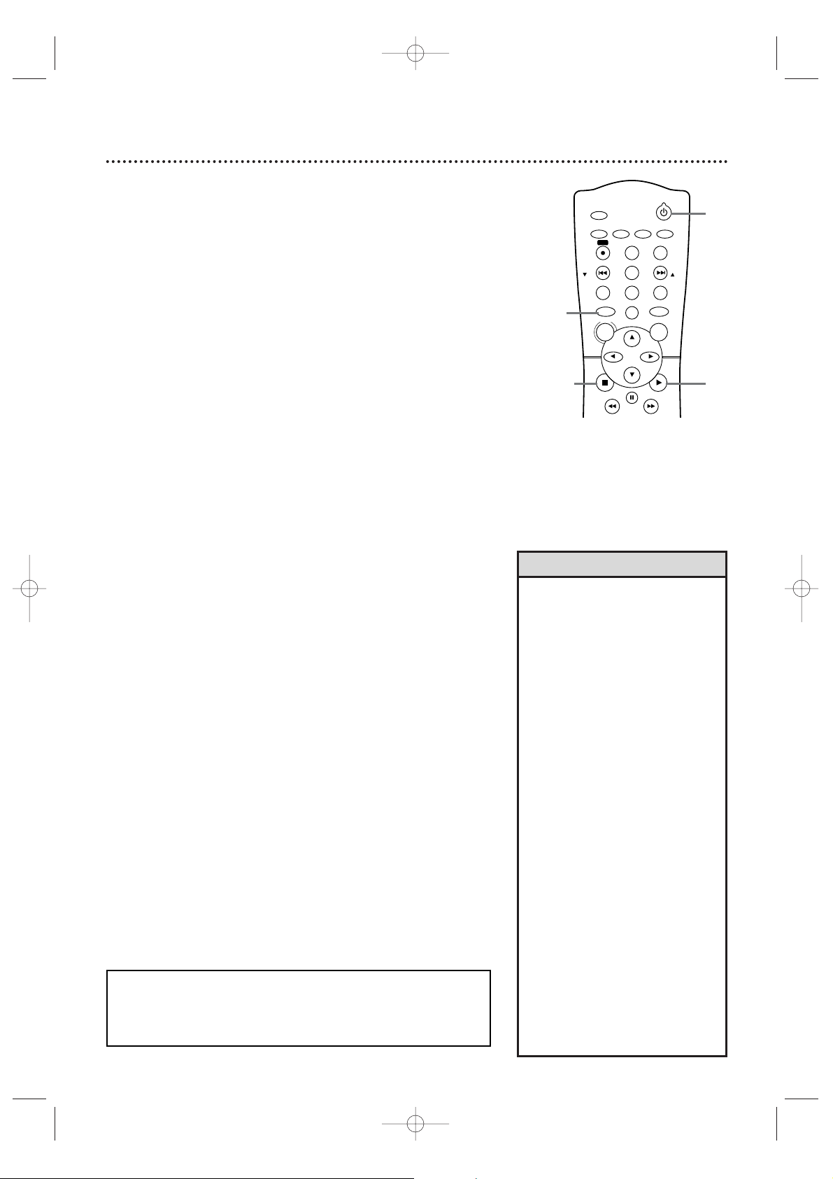
22 Remote Control
AUDIO/BAND Button
Press to choose a DVD audio
language or an Audio CD sound
mode.
Details are on page 66.
Press to choose FM or AM in Tuner
mode. Details are on page 75.
SETUP/PROG Button
Press while play is stopped to access
the DVD Player’s Setup menu.Press
to preset radio stations in Tuner
mode.Details are on page 76.
DISPLAY Button
Press to see status displays.
Details are on pages 33 and 73.
TITLE Button
Press to see a DVD Title menu.
Details are on page 54.
DVD Button
Press before using the remote
control for DVD features. Press to
put the System in DVD mode.
sBKLButtons
Press to select an item in a menu.
In T uner mode, press s or B to
choose a preset radio station.
REW h (rewind) Button
Press to fast reverse a DVD or
Audio CD.Details are on page 55.
Press to rewind a tape.
Details are on page 45.
SURROUND Button
Press to turn Surround Sound on
or off. Details are on page 49.
SOUND Button
Press to choose a Digital Sound
effect.Details are on page 49.
REPEAT Button
Press to play a Track,Audio CD,
Title, or Chapter repeatedly.
Details are on page 59.
SUBTITLE Button
Press to select a language for DVD
subtitles.
Details are on page 61.
ANGLE Button
Press to see a DVD picture from a
different angle.Details are on page 61.
ZOOM Button
Press to enlarge the DVD,JPEG, or
Picture CD image.
Details are on page 62.
C-RESET/CLEAR Button
Press to remove VCR menus.Press
to reset the tape counter. Details are
on page 43.
Press to clear a menu setting.
TUNER Button
Press before using the remote
control for Tuner features.Press to
put the System in Tuner mode.
OK Button
Press to confirm or select menu
items.
PLAY B Button
Press to begin Disc or tape playback.
PAUSE k Button
Press to pause Disc playback or to
advance the picture one frame at a
time. Details are on page 58. Press to
pause or resume VCR recording.
Details are on page 34. Press to
pause a tape.Details are on page 45.
SLOW Button
Press to view a videotape in slow
motion.
Details are on page 45.
SEARCH MODE Button
In DVD mode,press to search for a
specific Title/Chapter/T rack/Time.
Details are on pages 56-57. In VCR
mode, press for a Time Search or an
Index Search.Details are on page 44.
A-B REPEAT Button
Press to set up A-B Repeat. Details
are on page 59.
VOLUME Buttons
Press to adjust the volume.Press “+”
to increase the volume.Press “–” to
decrease the volume.
MX5100VR.qxd 6/04/2004 3:37 PM Page 22
TIMER SET
SETUP/
AUDIO/
PROG
BAND
REC
DISPLAY
SKIP/
C-RESET
CH
CLEAR
TITLE RETURNMODE/SPEED
TUNER
DISC
MENU
REW FF
PAUSE
1
2
456
789
0
+10
SOUNDSURROUND
PHILIPS
SUBTITLE
3
REPEAT
STANDBY-ON
ANGLE
ZOOM
SKIP/
CH
VCRDVD
OK
PLAYSTOP
SLOW
VCR/TV
SEARCH MODE
REPEAT
A-B
VOLUME
+–
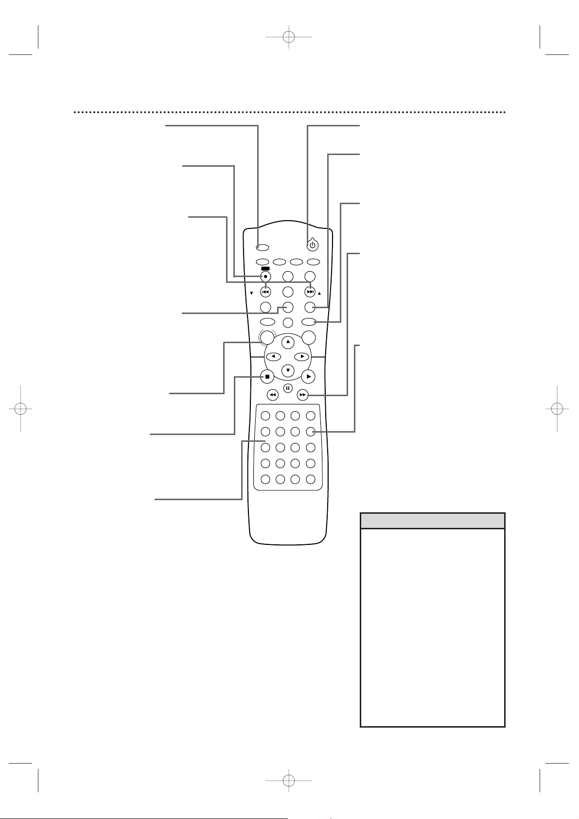
Page 23
Remote Control (cont’d) 23
•For DVD Player features,press
DVD before pressing other
buttons. To put the System in DVD
mode, press DVD or SOURCE so
the red DVD light appears on the
front of the System.
•For VCR features,press VCR before
pressing any other buttons. To put
the System in VCR mode, press
VCR or SOURCE so the red VCR
light appears on the front of the
System.
•For T uner features, press TUNER
before pressing any other buttons.
To put the System in Tuner mode ,
press TUNER or SOURCE so the
red TUNER light appear s on the
front of the System.
Helpful Hints
STANDBY-ON yyButton
Press to turn the power on or off.
RETURN Button
Press to return to the previous level
of the DVD Player’s Setup menu or
to remove the Setup menu.
VCR Button
Press before using the remote
control for VCR features.Press to put
the System in VCR mode.
FF g (fast forward) Button
In DVD mode,press to fast forward
the Disc.Details are on page 55.
Press when DVD playback is paused
to start slow motion playback.Details
are on page 62.
In VCR mode,press to fast forward
the tape.Details are on page 45.
VCR/TV Button
With the System in VCR or DVD
mode,press to select VCR or TV
position.
Select VCR position in VCR mode to
watch a tape or to watch/record TV
programs (changing channels at the
System).
Select VCR position in DVDmode to
watch a DVD.
Use TV position to watch TV
channels (changing channels at the
TV) or watch one program while
recording another.Details are on page
35.
TIMER SET Button
Press to set a timer recording.
Details are on pages 38-40.
REC (record) I Button
Press to start a VCR recording.
Details are on page 34.
SKIP j/CH p and
SKIP i/CH o Buttons
In DVD mode,press to skip
Chapters or Tracks. In VCR mode,
press to change TV channels at the
System.In Tuner mode, press and
hold to search radio stations.Or,
press to increase or decrease the
frequency by one-tenth.
MODE/SPEED Button
Press to set a Program.Details are
on page 63. Press to start Random
play. Details are on page 63.
Press to select the VCR’s recording
speed (SP or SLP).Details are on
pages 34 and 77.
DISC/MENU Button
Press to access or remove a DVD
Disc menu or the VCR menu.
STOP C Button
Press to stop Disc playback,tape
playback,or recording.
In Tuner mode, press to stop
presetting radio stations.
Number Buttons
In DVD mode,press to select a
Track or Chapter for playback.Use
the +10 button for items 10 and
above.Details are on page 57. In
VCR mode, use to select TV
channels.Enter channel numbers as
a two-digit number for the quickest
results (to select channel 6,press
0,6).For channels 100 and above,
enter a three-digit number (for
channel 117,press 1, 1, 7).If you
have Cable TV, channels 1-125 are
possible. If you have an antenna,
channels 2-69 are possible. The +10
button has no effect in VCR mode .
In Tuner mode, press the Number
buttons to choose a preset radio
station.
MX5100VR.qxd 6/04/2004 3:37 PM Page 23
TIMER SET
SETUP/
AUDIO/
PROG
BAND
REC
DISPLAY
SKIP/
C-RESET
CH
CLEAR
TITLE RETURNMODE/SPEED
TUNER
DISC
MENU
REW FF
PAUSE
1
2
456
789
0
+10
SOUNDSURROUND
PHILIPS
SUBTITLE
3
REPEAT
STANDBY-ON
ANGLE
ZOOM
SKIP/
CH
VCRDVD
OK
PLAYSTOP
SLOW
VCR/TV
SEARCH MODE
REPEAT
A-B
VOLUME
+–
Page 24
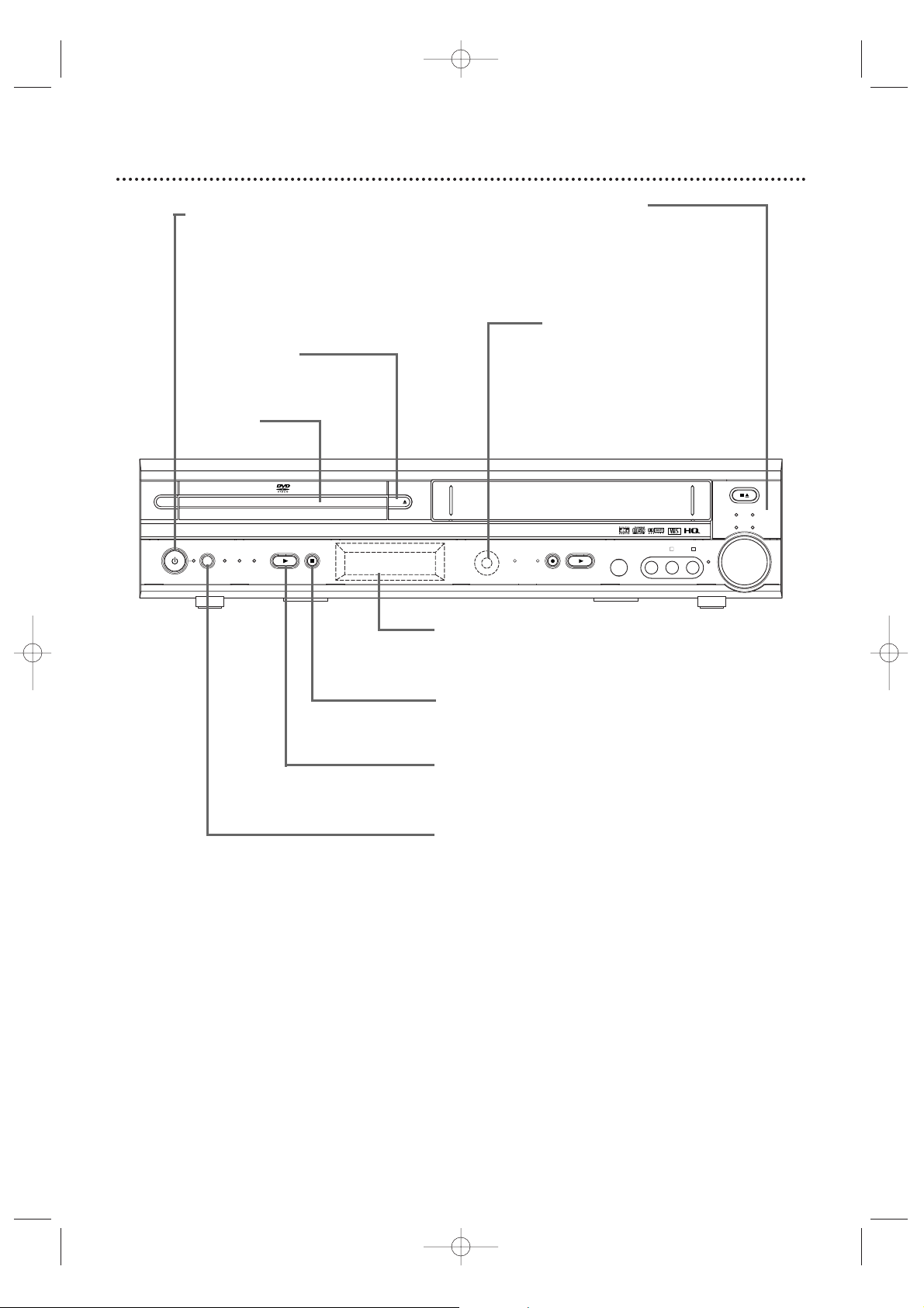
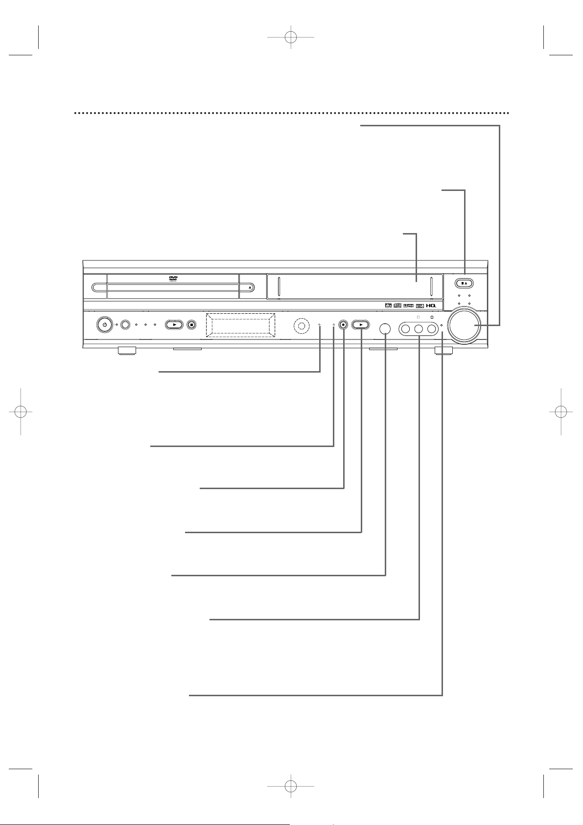
24 Front Panel
4 HEAD HI-FI STEREO
ONE TOUCH RECORDING • LONG PLAY
DVD VIDEO/CD PLAYER
OPEN
CLOSE
STANDBY-ON
SOURCE DVD VCR TUNER
PLAY STOP TIMER
REC
PLAY VIDEO
SURR
VOL
L - AUDIO - R
JAZZ
STOP/EJECT
CLASSIC
POP OPTIMAL
RECORD
IR
HEADPHONE
STANDBY-ON Button
and Light
Press to turn the power
on or off. The red light
appears when the power
is on.
OPEN/CLOSE A
Button (DVD)
Press to open or close
the Disc tray.
Disc T ray
Insert a Disc here.
Sound Lights
Each indicator lights according
to the sound effect you select
by pressing the SOUND
button on the remote.
Details are on page 49.
IR (Infrared)
Remote Sensor
Receives a signal from your
remote control so you can
work your System from a
distance. Point the remote
control toward the System’s IR
sensor, not your TV.
Display
Messages about current operations appear here.
Details are on page 26.
STOP C Button (DVD)
Press to stop Disc playback.
Details are on page 21.
PLAY B Button (DVD)
Press to start Disc playback.
Details are on page 21.
SOURCE Button
and Lights (DVD,VCR,TUNER)
Press to select DVD mode, VCR mode or Tuner
mode.The red DVD light appears in DVD mode.The
red VCR light appears in VCR mode.The red TUNER
light appears in Tuner mode.
MX5100VR.qxd 6/04/2004 3:37 PM Page 24
Page 25
Front Panel (cont’d) 25
4 HEAD HI-FI STEREO
ONE TOUCH RECORDING • LONG PLAY
DVD VIDEO/CD PLAYER
OPEN
CLOSE
STANDBY-ON
SOURCE DVD VCR TUNER
PLAY STOP TIMER
REC
PLAY VIDEO
SURR
VOL
L - AUDIO - R
JAZZ
STOP/EJECT
CLASSIC
POP OPTIMAL
RECORD
IR
HEADPHONE
TIMER REC Light
This red light glows when the System is set for a timer
recording or during a One-Touch Recording.
It flashes if a timer recording is set but no tape is in the
System.It flashes when all timer recordings or One-Touch
Recordings are finished.
RECORD Light
This red light appears during VCR recording. It flashes when
recording is paused.
RECORD I Button (VCR)
Press once to start a recording.Press repeatedly to start a
One-Touch Recording.
Details are on page 36.
PLAY B Button (VCR)
Press to play a video cassette.Press to release Slow, Search,
or Still mode and return to playback.
Details are on page 45.
HEADPHONE Jack
Connect headphones (not supplied) here. When headphones
are connected,Surround Sound is not available.
AUDIO and VIDEO In Jacks
Connect audio and video cables coming from the audio and
video out jacks of a camcorder, another VCR,another DVD
Player, or audio system here.This will be useful if you want to
copy a videotape or watch material that is playing on other
equipment.
Details are on page 37.
SURR (Surround) Light
This light appears when Surround Sound is On.
Details are on page 49.
VOLUME Dial
Turn clockwise to increase the volume;
turn counter-clockwise to decrease the
volume. The volume level will appear
briefly on the display panel.
STOP/EJECT CA Button (VCR)
Press once to stop tape playback. When
play is stopped,press to eject the tape.
Cassette Compartment
Insert a videotape here.
MX5100VR.qxd 6/04/2004 3:37 PM Page 25
Page 26
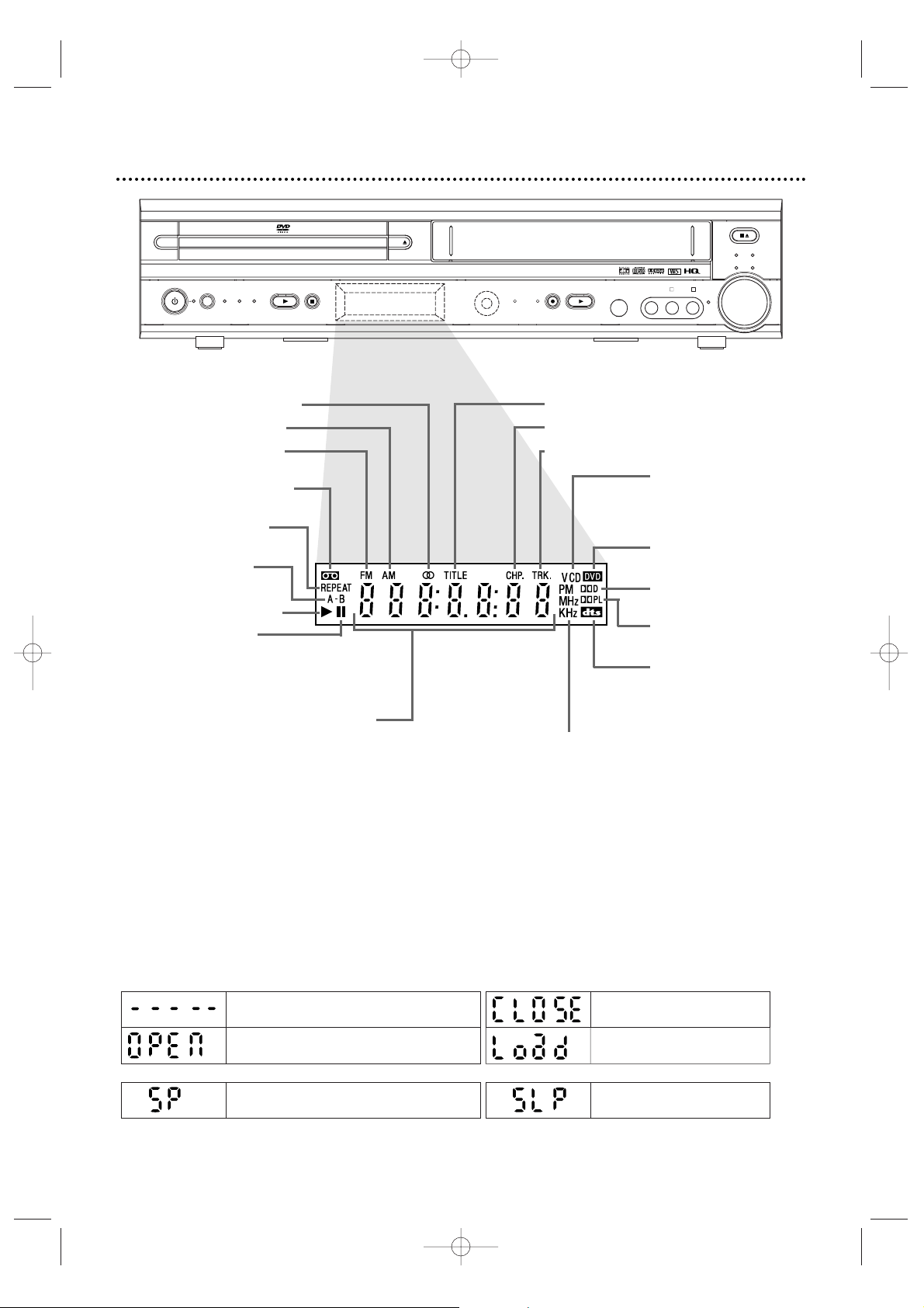
26 Display Panel
4 HEAD HI-FI STEREO
ONE TOUCH RECORDING • LONG PLAY
DVD VIDEO/CD PLAYER
OPEN
CLOSE
STANDBY-ON
SOURCE DVD VCR TUNER
PLAY STOP TIMER
REC
PLAY VIDEO
SURR
VOL
L - AUDIO - R
JAZZ
STOP/EJECT
CLASSIC
POP OPTIMAL
RECORD
IR
HEADPHONE
Appears after the Disc tray closes if the tray is empty, if
there is an error reading the Disc, or if an unacceptable
Disc is installed.
Appears for five seconds to indicate SLP
as recording speed.
Tray is opening or is open.
Tray is closing.
Disc is loading.
DVD
Appears for five seconds to indicate SP as recording speed.
VCR
Display Messages
Appears when a videotape
is loaded.
Appears during repeat
play.
Appears during A-B
Repeat play.
Appears during play.
Appears when play is
paused.
CD appears when an
Audio CD is loaded.
VCD appears when a
Video CD is loaded.
DVD appears when a
DVD is in the System.
Indicates Dolby Digital is
available.
Indicates Dolby ProLogic
is available.
Indicates DTS is available.
Indicates a stereo broadcast
Indicates an AM station
Indicates an FM station
Shows elapsed playing time of current
Title/Track.When a Title/Chapter/Track
changes,the Title/Chapter/T rack number
appears briefly.
PM:Indicates a PM time .
AM does not appear.
MHz:Indicates an FM station.
KHz:Indicates an AM station.
Indicates Repeat Title is active.
Indicates Repeat Chapter is active.
Indicates Repeat Track is active.
MX5100VR.qxd 6/04/2004 3:37 PM Page 26
Page 27
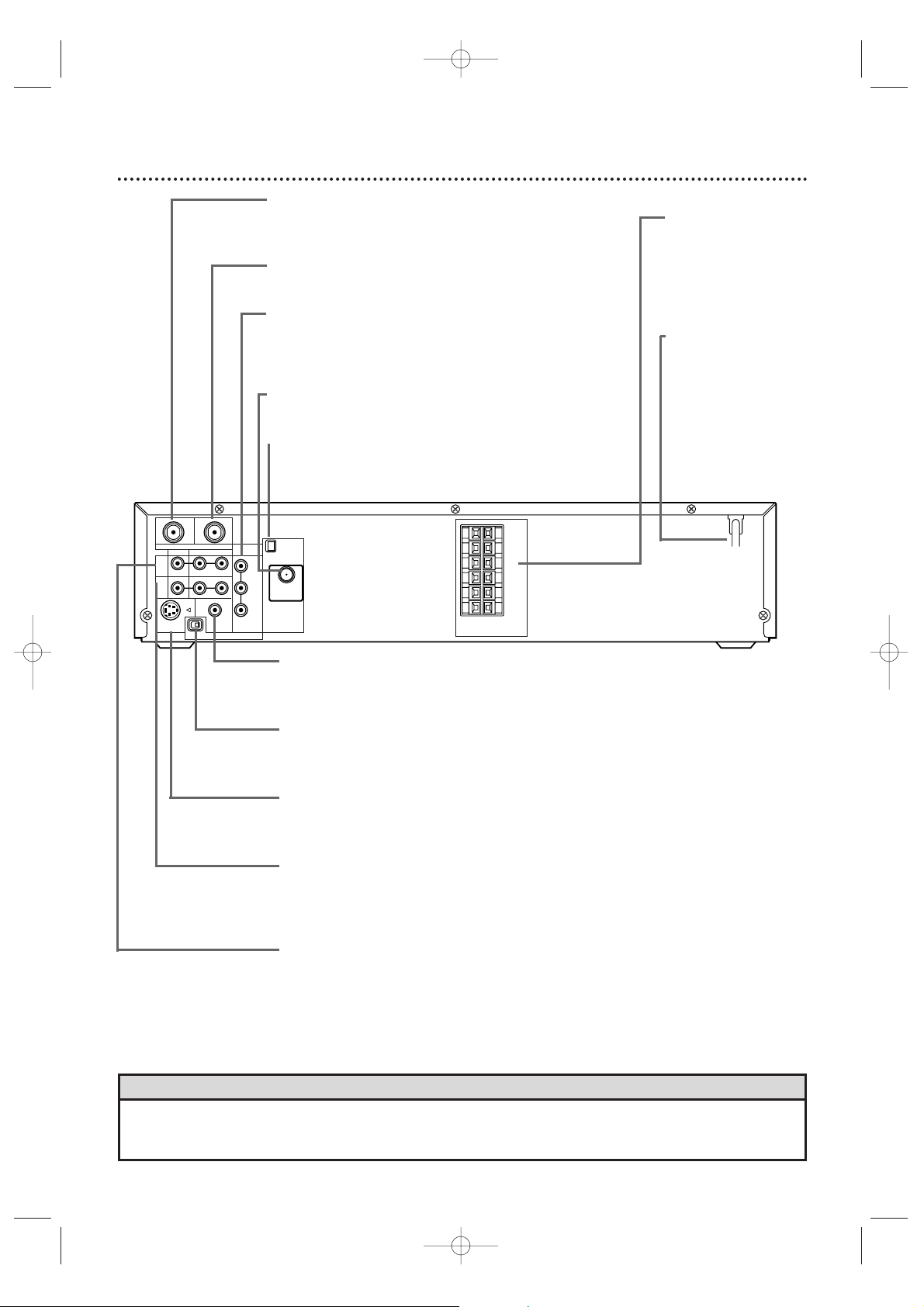
Rear Panel 27
• The S-VIDEO OUT, COMPONENT VIDEO OUT, and DIGITAL AUDIOOUT COAXIAL jacks are only useful in
DVD mode.To have sound and picture in VCR mode, connect either the RF coaxial cable or the audio/video
cables. Details are on pages eight and 11.
Helpful Hint
VIDEO
TV ANTENNA
AUDIO
R L
PROGRESSIVE
OUT
IN
ANTENNA 75Ω
ANTENNA 75Ω
Y
Pb/Cb
Pr/Cr
FM
(75Ω)
DIGITAL
AUDIO OUT
COAXIAL
S-VIDEO
OUT
VCR
IN
DVD/
VCR
OUT
COMPONENT
VIDEO OUT
AM
FL
FR
C
SL
SR
W
SPEAKER (4Ω)
P I
TV ANTENNA OUT Jack
Use an RF coaxial cable to connect this jack to the
ANTENNA IN jack on your TV, Cable Box,or Satellite
Receiver. Details are on pages 8-10.
TV ANTENNA IN Jack
Connect your antenna or Cable TV/Satellite signal
here.Details are on pages 8-15.
COMPONENT VIDEO OUT Jacks
(Y Pb/Cb Pr/Cr) (green,blue, red)
Connect component video cables here and to the
Component Video In jacks of a TV.This supplies the
picture only for the DVD Player. Details are on page 12.
FM jack
Connect the supplied wire FM antenna or an exterior
FM antenna (not supplied) here.Details are on page 16.
AM jack
Connect the supplied AM antenna here.
Details are on page 16.
DIGITAL AUDIO OUT COAXIAL Jack (black)
Connect a coaxial digital audio cable here and to the Coaxial Digital
Audio In jack of a Stereo.This supplies audio only for the DVD
Player. Details are on page 15.
P/I PROGRESSIVE Switch
Set to P (Progressive) only if you are using a Component Video
connection to a TV with Progressive Scan.Details are on page 12.
Set to I (Interlace) for all other connections.
S-VIDEO OUT Jack
Connect an S-Video cable here and to the S-Video In jack of a TV.
This supplies the picture only for the DVD Player.
Details are on page 13.
AUDIO and VIDEO (VCR IN) Jacks
Connect audio and video cables from a camcorder,VCR, DVD Player,
or audio source here.This will be useful if you want to copy a
videotape or watch/hear material that is playing on other equipment.
Details are on page 37.
AUDIO and VIDEO (DVD/VCR OUT) Jacks
Connect audio and video cables here and to the Audio/Video In
jacks of a TV or Stereo.Details are on pages 11-14.These jacks
provide audio/video for both the DVD Player and the VCR.
SPEAKER jacks
Connect the supplied
FRONT, CENTER,
and REAR speakers
and Subwoofer here.
Details are on page 17.
AC Power Cord
Connect the power
cord to a standard
AC outlet to supply
power to the System.
MX5100VR.qxd 6/04/2004 3:37 PM Page 27
Page 28
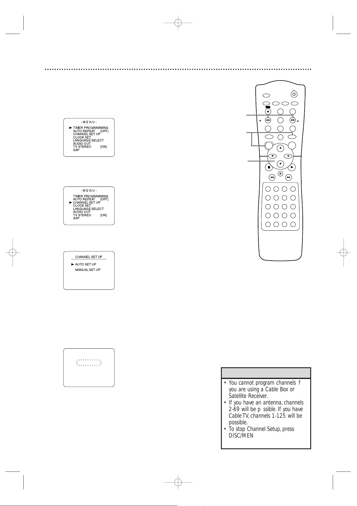
28 Channel Setup
Although your System may automatically memorize the channels you
receive when you turn it on for the first time,you can set up the
channels again.
1
Press VCR, then press DISC/MENU so the main menu
appears.
2
Press o or p to select CHANNEL SET UP. Then,
press B.
3
Press o or p to select AUTO SET UP. Press B.
4
AUTO SET UP will flash while the System sets up the available
channels. When setup is complete , the lowest available channel
will appear on the TV.
Now when you
press SKIP i /CH o or SKIP j /CH
p,you will scan only through available channels.You still can
select any channel using the Number buttons.
•You cannot program channels if
you are using a Cable Box or
Satellite Receiver.
• If you have an antenna, channels
2-69 will be possible. If you have
Cable TV, channels 1-125 will be
possible.
•To stop Channel Setup, press
DISC/MENU while AUTO SET UP
is flashing.
Helpful Hints
STANDBY-ON
TIMER SET
VCR/TV
SEARCH MODE
REPEAT
TUNER
3
456
789
SLOW
0
+10
2
1
VCRDVD
CLEAR
DISPLAY
SETUP/
PROG
TITLE RETURNMODE/SPEED
C-RESET
AUDIO/
BAND
ANGLE
SUBTITLE
ZOOM
DISC
MENU
OK
PAUSE
REW FF
PLAYSTOP
SKIP/
CH
SKIP/
CH
REPEAT
SOUNDSURROUND
+–
VOLUME
REC
A-B
PHILIPS
4
2-3
1
MX5100VR.qxd 6/04/2004 3:37 PM Page 28
-MENU-
TIMER PROGRAMMING
B
AUTO REPEAT
CHANNEL SET UP
CLOCK SET
LANGUAGE SELECT
AUDIO OUT
TV STEREO
SAP
-MENU-
TIMER PROGRAMMING
AUTO REPEAT
CHANNEL SET UP
B
CLOCK SET
LANGUAGE SELECT
AUDIO OUT
TV STEREO
SAP
[OFF]
[ON]
[OFF]
[ON]
B
CH 01
AUTO SET UP
Page 29
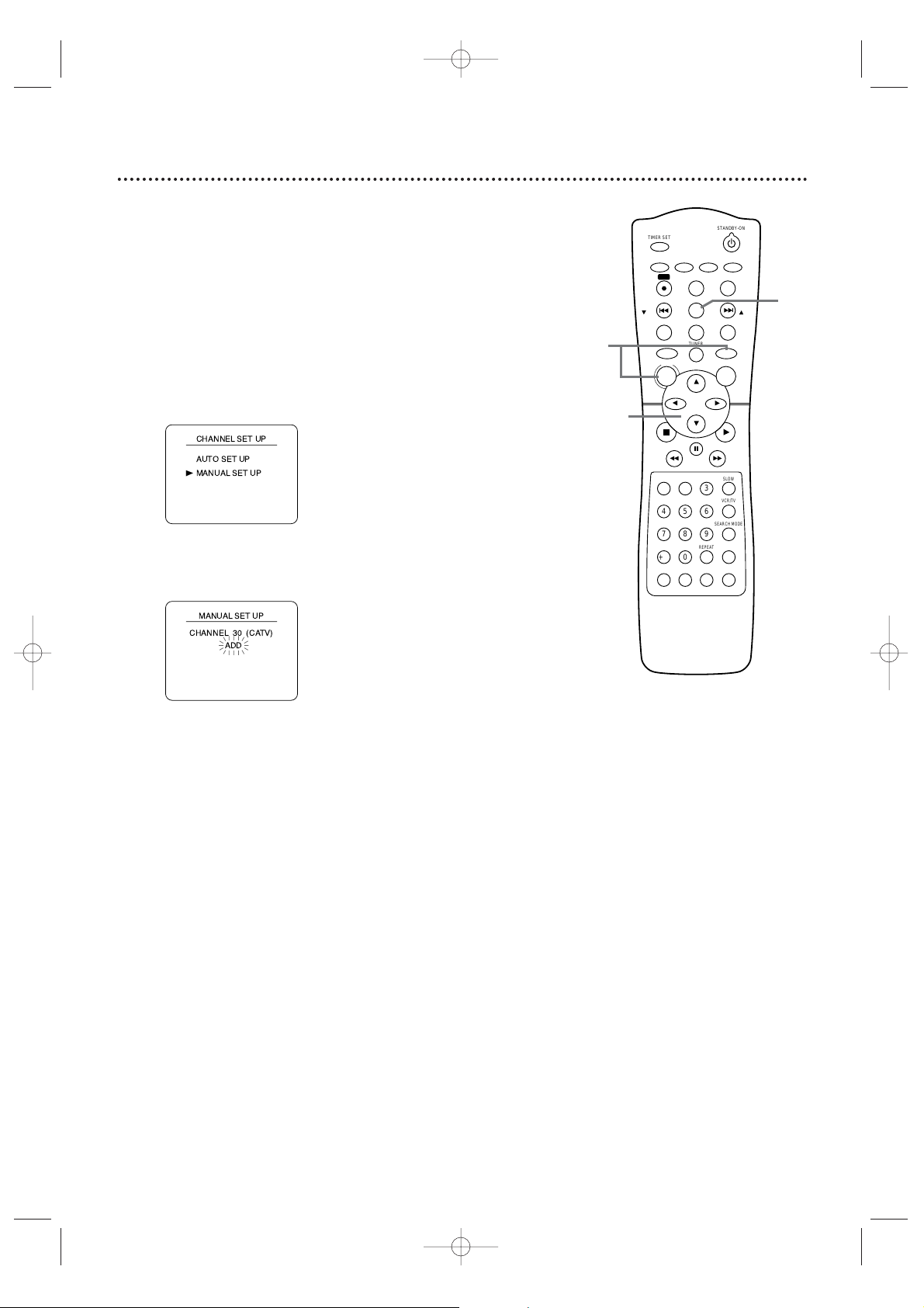
Channel Setup (cont’d) 29
Adding/Deleting Channels
You may want to add or delete TV channels if your channel lineup
changes or if you no longer watch some channels.
1
Press VCR, then press DISC/MENU so the main menu
appears.
2
Press o or p to select CHANNEL SET UP, then
press B.
3
Press o or p to select MANUAL SET UP, then press
B.
4
Press o or p until the channel number you want to
add or delete appears on the screen.
5
Press B or s so ADD or DELETE flashes on the
screen.
6
While your choice is flashing,press
C-RESET/CLEAR.The channel you added or deleted will be
the current channel. Added channels are available when you
flip through channels using the SKIP i /CH o and SKIP
j /CH p buttons. You still can select deleted channels with
the Number buttons.
2-5
1
6
MX5100VR.qxd 6/04/2004 3:37 PM Page 29
B
TIMER SET
AUDIO/
SETUP/
BAND
PROG
REC
DISPLAY
C-RESET
SKIP/
CH
TITLE RETURNMODE/SPEED
DISC
MENU
REW FF
1
2
456
789
0
+10
SOUNDSURROUND
PHILIPS
CLEAR
TUNER
PAUSE
SUBTITLE
3
REPEAT
STANDBY-ON
ANGLE
ZOOM
VCRDVD
OK
SLOW
VCR/TV
SEARCH MODE
REPEAT
A-B
VOLUME
+–
SKIP/
CH
PLAYSTOP
Page 30
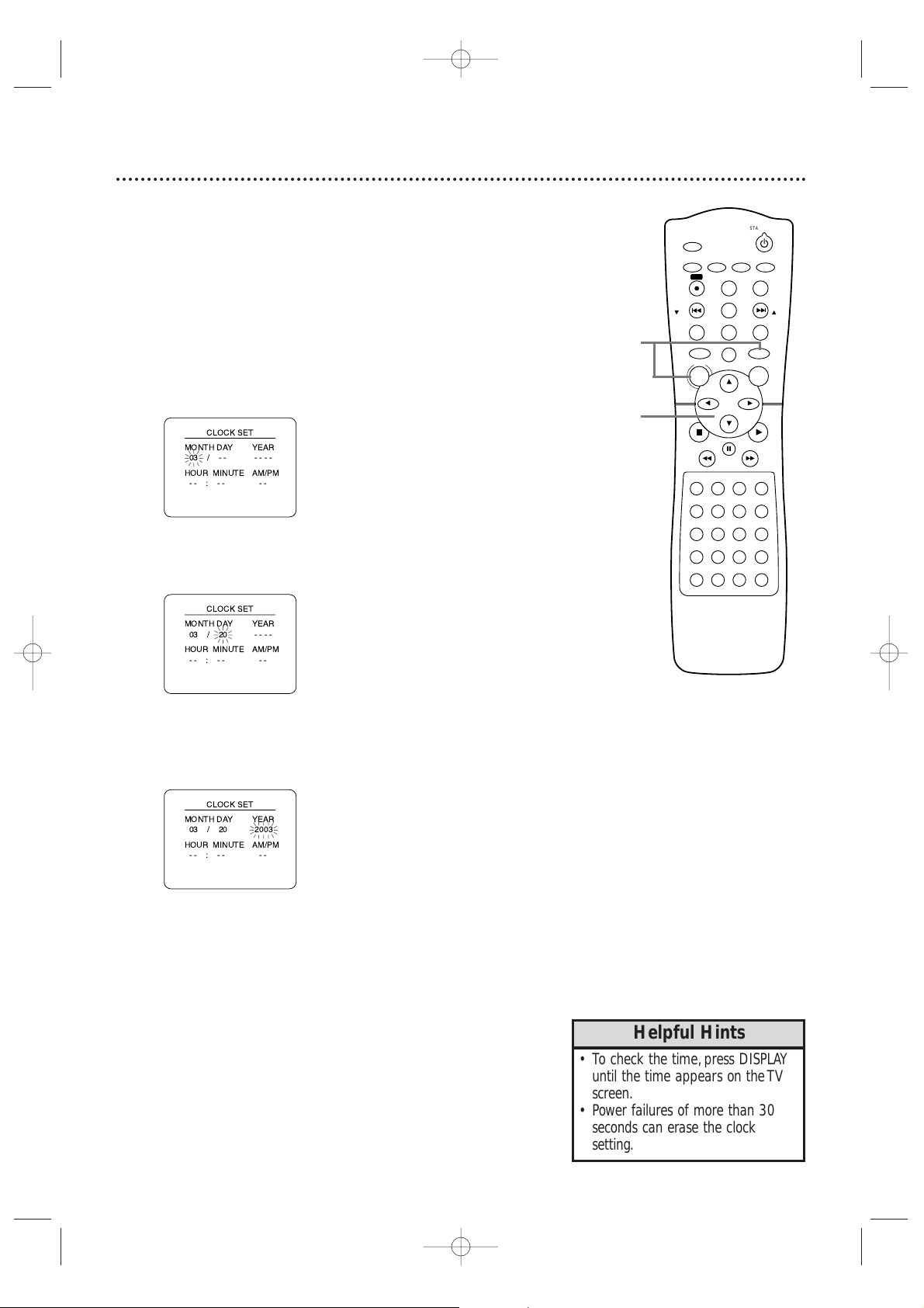
30 Clock (VCR)
Follow these steps to set the VCR clock. Make sure:
● The System is on and in VCR mode. Press VCR so the red VCR
light appears on the front of the System.
1
Press DISC/MENU.If the clock has never been set,the
CLOCK SET menu will appear. Go to step 3.
2
Press o or p to select CLOCK SET, then press B.
3
While the MONTH space is flashing, press o or p
until the month appears. Then, press B.
4
While the DAY space is flashing, press o or p until
the day appears. Then, press B.
5
While the YEAR space is flashing, press o or p until
the year appears. Press B. The day of the week will
appear automatically.
•To check the time , press DISPLAY
until the time appears on the TV
screen.
• Power failures of more than 30
seconds can erase the clock
setting.
Helpful Hints
STANDBY-ON
TIMER SET
VCR/TV
SEARCH MODE
REPEAT
TUNER
3
456
789
SLOW
0
+10
2
1
VCRDVD
CLEAR
DISPLAY
SETUP/
PROG
TITLE RETURNMODE/SPEED
C-RESET
AUDIO/
BAND
ANGLE
SUBTITLE
ZOOM
DISC
MENU
OK
PAUSE
REW FF
PLAYSTOP
SKIP/
CH
SKIP/
CH
REPEAT
SOUNDSURROUND
+–
VOLUME
REC
A-B
PHILIPS
2-5
1
MX5100VR.qxd 6/04/2004 3:37 PM Page 30
Page 31

Clock (VCR) (cont’d) 31
6
While the HOUR space is flashing, press o or p until
the hour appears. Then, press B.
7
While the MINUTE space is flashing, press o or p
until the minute appears. Then, press B.
8
While the AM or PM space is flashing, press o or p to
select AM or PM.
Your selection will flash on the screen in the AM/PM space.
9
Press C-RESET/CLEAR or B to star t the clock.
•To reset the clock, follow steps 1-2
on page 30.Select the information
you want to change using
B or
s.When the information is
flashing,use
o or p to enter the
correct information.Press
C-RESET/CLEAR to set the clock.
Helpful Hints
STANDBY-ON
TIMER SET
VCR/TV
SEARCH MODE
REPEAT
TUNER
3
456
789
SLOW
0
+10
2
1
VCRDVD
CLEAR
DISPLAY
SETUP/
PROG
TITLE RETURNMODE/SPEED
C-RESET
AUDIO/
BAND
ANGLE
SUBTITLE
ZOOM
DISC
MENU
OK
PAUSE
REW FF
PLAYSTOP
SKIP/
CH
SKIP/
CH
REPEAT
SOUNDSURROUND
+–
VOLUME
REC
A-B
PHILIPS
6-9
9
MX5100VR.qxd 6/04/2004 3:37 PM Page 31
B
Page 32

32 Language (VCR)
Follow the steps below to change the language of the VCR on-screen
displays and menus.
1
Press VCR, then press DISC/MENU.
2
Press o or p to choose LANGUAGE SELECT, then
press B.
3
Press o or p to choose ENGLISH, FRANCAIS
(French),or ESPAÑOL (Spanish).
4
Press C-RESET/CLEAR to remove the menu.
• If you select French or Spanish and
need English:
1) Press DISC/MENU so the main
MENU appears.
2) Press p to c hoose SELECTION
LANGUE or SELEC. IDIOMA, then
press B.
3) Press o or p to select ENGLISH.
4) Press C-RESET/CLEAR.
Helpful Hint
STANDBY-ON
TIMER SET
VCR/TV
SEARCH MODE
REPEAT
TUNER
3
456
789
SLOW
0
+10
2
1
VCRDVD
CLEAR
DISPLAY
SETUP/
PROG
TITLE RETURNMODE/SPEED
C-RESET
AUDIO/
BAND
ANGLE
SUBTITLE
ZOOM
DISC
MENU
OK
PAUSE
REW FF
PLAYSTOP
SKIP/
CH
SKIP/
CH
REPEAT
SOUNDSURROUND
+–
VOLUME
REC
A-B
PHILIPS
2-3
1
4
MX5100VR.qxd 6/04/2004 3:37 PM Page 32
-MENU-
TIMER PROGRAMMING
B
AUTO REPEAT
CHANNEL SET UP
CLOCK SET
LANGUAGE SELECT
AUDIO OUT
TV STEREO
SAP
-MENU-
TIMER PROGRAMMING
AUTO REPEAT
CHANNEL SET UP
CLOCK SET
LANGUAGE SELECT
B
AUDIO OUT
TV STEREO
SAP
B
[OFF]
[ON]
[OFF]
[ON]
Page 33

VCR Status Displays 33
You may access status displays by pressing DISPLAY on the remote.The
displays may include the current time,channel, and other information.
1
Press DISPLAY.The COUNT display will appear for five
seconds.After five seconds, only the real-time tape counter
will appear.This counter shows you the elapsed playing time of
the tape (from the point at which the counter was set to
zero).The counter display will also appear on the System’s
display panel.
2
Press DISPLAY again.The CLOCK display will appear for
five seconds. After five seconds, only the time will appear (the
clock must be set).(If you are watching TV, the channel
number and the availability of stereo or second audio will also
appear.) The current time will also appear on the display panel.
3
Press DISPLAY again to remove all the displays.
• If the channel you select has no
broadcast,the screen will be solid
blue.
•You cannot access a status display
when viewing a still picture, during
slow motion,or during forward and
reverse searching.
• Channel numbers appear on the
TV screen for a few seconds each
time you change channels.
Helpful Hints
STANDBY-ON
TIMER SET
VCR/TV
SEARCH MODE
REPEAT
TUNER
3
456
789
SLOW
0
+10
2
1
VCRDVD
CLEAR
DISPLAY
SETUP/
PROG
TITLE RETURNMODE/SPEED
C-RESET
AUDIO/
BAND
ANGLE
SUBTITLE
ZOOM
DISC
MENU
OK
PAUSE
REW FF
PLAYSTOP
SKIP/
CH
SKIP/
CH
REPEAT
SOUNDSURROUND
+–
VOLUME
REC
A-B
PHILIPS
1-3
MX5100VR.qxd 6/04/2004 3:37 PM Page 33
Page 34

34 Videotape Recording
Read and follow the steps below to record a television program onto a
videotape.Before you begin,make sure the System is in VCR
mode. Press VCR so the red VCR light appears on the front of
the System.
1
Turn on the TV and set it to channel 3 or 4 or the
Video In channel. If you connected the System to the TV
using the supplied audio and video cables,select your TV’s
Video In channel.Details are on page 11.
If you connected the System to the TV using the supplied RF
coaxial cable, choose channel 3 (or 4) at the TV.
Details are on pages 8-10.
2
Insert a tape with its record tab intact into the
cassette compartment of the System. If tape playback
begins,press STOP
C.
3
Press MODE/SPEED until the desired tape speed (SP
or SLP) appears briefly on the TV screen and the
System’s display panel.
Details about tape speed are on page 77.
4
Press SKIP i /CH o or SKIP j /CH p or the
Number buttons to select the TV channel to record.
5
Press REC I to star t recording.The red RECORD light
will appear on the front of the System.
6
To pause the recording,press PAUSE k once. The red
RECORD light will flash.To resume recording, press REC
I or press PAUSE k again.The red RECORD light will
come on again.
7
To stop recording,press STOP C.
Recording Prevention
Video Cassettes have record tabs to ensure that recordings are not
accidentally erased.
1
To prevent recording,break off the tab with a
screwdriver.
2
To allow recording,cover the hole with clear tape.
• Other recording options are on
pages 35-41.
• The VCR will record in a preset
volume.
•Pause will switch to Stop after five
minutes to protect the VCR and the
tape from damage.When a
recording is paused,review the
pause time remaining with the I
marks on the TV screen.Each I
mark equals one minute remaining.
During the last minute of paused
recording,the I mark will flash.
• If any menu is on the TV screen,the
REC I button on the remote does
not function.Press C-RESET/CLEAR
to remove the menu.Then,press
REC I.Or, use the RECORD I
button on the front of the System.
Helpful Hints
Remove the
tab to prevent
recording.
Cover the
hole to allow
recording.
STANDBY-ON
TIMER SET
VCR/TV
SEARCH MODE
REPEAT
TUNER
3
456
789
SLOW
0
+10
2
1
VCRDVD
CLEAR
DISPLAY
SETUP/
PROG
TITLE RETURNMODE/SPEED
C-RESET
AUDIO/
BAND
ANGLE
SUBTITLE
ZOOM
DISC
MENU
OK
PAUSE
REW FF
PLAYSTOP
SKIP/
CH
SKIP/
CH
REPEAT
SOUNDSURROUND
+–
VOLUME
REC
A-B
1
Turn on the TV.
2
Insert a tape in the System.
3
7
5
4
6
MX5100VR.qxd 6/04/2004 3:37 PM Page 34
Page 35

Recording One Channel/Watching Another 35
1
Press VCR,then press REC I to record the current TV
channel. Details are on page 34.
2
Press VCR/TV once to put the System in TV position.
3
Use the TV remote control to select the channel you
want to watch at the TV.
4
To return to the channel being recorded, use the TV
remote control to select channel 03 or 04 at the TV.
Details are on page eight. Or,if you connected the System to
the TV using audio and video cables, select the TV’s correct
Video In channel.Details are on page 11.
5
Press VCR/TV on the System’s remote control to put
the System back in VCR position.The channel being
recorded will appear on the TV screen.
6
Press STOP C to stop the recording.
• If you use a Cable Box or Satellite
Receiver,you may not be able to
watch one channel while recording
another.See pages 9-10 for
details.
Helpful Hints
STANDBY-ON
TIMER SET
VCR/TV
SEARCH MODE
REPEAT
TUNER
3
456
789
SLOW
0
+10
2
1
VCRDVD
CLEAR
DISPLAY
SETUP/
PROG
TITLE RETURNMODE/SPEED
C-RESET
AUDIO/
BAND
ANGLE
SUBTITLE
ZOOM
DISC
MENU
OK
PAUSE
REW FF
PLAYSTOP
SKIP/
CH
SKIP/
CH
REPEAT
SOUNDSURROUND
+–
VOLUME
REC
A-B
PHILIPS
3
Select the channel you want
to watch at the TV.
4
Select channel 03,04, or
Video In at the TV.
6
2,5
1
1
MX5100VR.qxd 6/04/2004 3:37 PM Page 35
Page 36

36 One-Touch Recording
One-Touch Recording (OTR) lets you set a timed recording 30
minutes to eight hours long.Before you begin:
● Place the System in VCR mode. Press VCR so the red VCR light
appears on the front of the System.
● Select a recording speed (SP, SLP) with the MODE/SPEED button.
● Put a videotape in the cassette compartment. Make sure the tape’s
record tab is intact and the tape is long enough to record the
program(s).
1
Press SKIP i /CH o or SKIP j /CH p or the
Number buttons to select the channel you want to
record.
2
Press RECORD I on the front of the System until the
desired recording length (30 minutes to eight hours)
appears on the TV screen. Recording will begin. The
RECORD light and the TIMER REC light will appear on the
front of the System.
Stopping an OTR
To stop an OTR before recording is finished,press STOP C on the
remote control or STOP/EJECT C A on the front of the System.
To cancel the OTRbut continue recording,press RECORD I on
the front of the System repeatedly until REC appears in the upper
left corner of the TV screen.
When an OTR finishes,the System will switch to DVD mode and/or
turn itself off. The TIMER REC light will flash because the VCR of the
System is still on standby for timer recordings.Press TIMER SET on
the remote or STOP/EJECT C A on the System to cancel timer
standby and use the VCR of the System normally again.
• The remaining recording time will
appear on the display panel.Press
DISPLAY to see it on the TV screen.
•To change the recording length
while an OTR is in progress,press
RECORD Ion the front of the
System.
•You cannot star t a timed OTR with
the REC I button on the remote.
•You cannot pause an OTR.
• If the end of the tape is reached
during an OTR,the VCR will stop
recording,eject the tape, and
switch to DVD mode and/or turn
off. The TIMER REC light will flash.
Press TIMER SET on the remote or
STOP/EJECT
CA
on the System
to cancel timer standby and use
the VCR again.
• If you press TIMER SET for a
Timer Recording,the OTR will stop
immediately.The System will switch
to DVD mode or turn off for the
recording.
Helpful Hints
2
Press RECORD I on the
front of the System.
STANDBY-ON
TIMER SET
VCR/TV
SEARCH MODE
REPEAT
TUNER
3
456
789
SLOW
0
+10
2
1
VCRDVD
CLEAR
DISPLAY
SETUP/
PROG
TITLE RETURNMODE/SPEED
C-RESET
AUDIO/
BAND
ANGLE
SUBTITLE
ZOOM
DISC
MENU
OK
PAUSE
REW FF
PLAYSTOP
SKIP/
CH
SKIP/
CH
REPEAT
SOUNDSURROUND
+–
VOLUME
REC
A-B
1
MX5100VR.qxd 6/04/2004 3:37 PM Page 36
OTR (0:30)
SP
Page 37

Rerecording (Tape Duplication) 37
1
Make the connections shown above.
2
System 1 will play your tape. Put a prerecorded tape into
the cassette compartment of System 1. Press VCR to
put the unit in VCR mode if necessary.
3
System 2 will record your tape.Insert a blank tape in the
cassette compartment of System 2. Press VCR to put
the unit in VCR mode if necessary.
4
Turn on the TV and set it to channel 03 (the RF output
channel of System 2).(To change the System’s output c hannel, see
step 6 on page eight.)
5
Point the remote control at System 2.Press Number
buttons 0, 0, 1 or 0, 0, 2. (See Helpful Hints at right.)
6
Press MODE/SPEED to select SP or SLP at System 2.
7
Press PLAY B (VCR) on the front of System 1 and
RECORD I on the front of System 2 at the same
time.
To stop recording,press STOP/EJECT CA on System 1, then
press STOP/EJECT CA on System 2.
VIDEO
TV ANTENNA
AUDIO
R L
PROGRESSIVE
OUT
IN
ANTENNA 75Ω
ANTENNA 75Ω
Y
Pb/Cb
Pr/Cr
FM
(75Ω)
DIGITAL
AUDIO OUT
COAXIAL
S-VIDEO
OUT
VCR
IN
DVD/
VCR
OUT
COMPONENT
VIDEO OUT
AM
FL
FR
C
SL
SR
W
SPEAKER (4Ω)
P I
VIDEO
TV ANTENNA
AUDIO
R L
PROGRESSIVE
OUT
IN
ANTENNA 75Ω
ANTENNA 75Ω
Y
Pb/Cb
Pr/Cr
FM
(75Ω)
DIGITAL
AUDIO OUT
COAXIAL
S-VIDEO
OUT
VCR
IN
DVD/
VCR
OUT
COMPONENT
VIDEO OUT
AM
FL
FR
C
SL
SR
W
SPEAKER (4Ω)
P I
System 1
(Plays tape)
System 2
(Records tape)
1.Audio cables from
red/white AUDIO
(DVD/VCR OUT) jacks of
System 1 to AUDIO (VCR
IN) jacks of System 2
2.Video cable from yellow
VIDEO (DVD/VCR OUT)
jack of System 1 to yellow
VIDEO (VCR IN) jack of
System 2
3. RF coaxial cable from
the TV ANTENNA OUT
jack of System 2 to the
TV’s ANTENNA IN Jack
These instructions show you how to copy videotapes. The illustration
uses two MX5100 Systems.Other VCRs or Camcorders may operate
differently.
• If you use the AUDIO and VIDEO
(VCR IN) jacks on the back of
System 2,press Number buttons
0,0, 1 at step 5. L1 will appear on
the TV screen and the System’s
display panel.
• If you use the AUDIO and VIDEO
In jacks on the front of System 2,
press Number buttons 0,0, 2 at
step 5.L2 will appear on the TV
screen and the System’s display
panel.
• Unauthorized recording of
copyrighted television programs,
videotapes, or other materials may
infringe on the rights of copyright
owners and violate copyright laws.
• If a program has copyright
protection,it may not record
clearly.
Helpful Hints
MX5100VR.qxd 6/04/2004 3:37 PM Page 37
Page 38

38 Timer Recording
Follow these steps to program the System’s VCR to record TV
programs while you’re away.Before you begin:
● Set up the TV channels at the System. Details are on page 28.
● Set the clock. Details are on pages 30-31.
● Put a tape in the cassette compartment. Make sure the tape’s
record tab is intact and the tape is long enough to record the
program(s).If the end of the tape is reached during a Timer
Recording,recording will stop.The tape will eject and the System
will turn off.
● Press VCR so the red VCR light appears on the front of the
System.
1
Press DISC/MENU so the MENU appears.
2
Press o or p to select TIMER PROGRAMMING.Then,
press B. Program numbers that do not have a timer
recording stored will flash.
3
Press o or p to select an empty program.Then, press
B.
4
Press o or p to select ONCE, DAILY, or WEEKLY.
Then, press B.
● ONCE - The VCR will record a TV program on any day you
choose, up to 12 months away.
● DAILY - The VCR will record a TV program at the same
time on the same channel every day, Monday through
Friday.
● WEEKLY - The VCR will record a TV program at the same
time on the same channel every week,for example, every
Monday.
•You cannot access the TIMER
PROGRAMMING menu at step 2
if the clock is not set.The CLOCK
SET menu will appear.Follow the
steps on pages 30-31 to set the
clock.
• Only programs that will air
Monday-Friday can be recorded on
a DAILY basis.If you select DAILY
at step 4,then enter a Saturday or
Sunday DATE at step 5, the
correct program will not be
recorded.The VCR will alter the
recording date (changing it to a
Monday-Friday date) and record a
different program than the one
you intended.
Helpful Hints
STANDBY-ON
TIMER SET
VCR/TV
SEARCH MODE
REPEAT
TUNER
3
456
789
SLOW
0
+10
2
1
VCRDVD
CLEAR
DISPLAY
SETUP/
PROG
TITLE RETURNMODE/SPEED
C-RESET
AUDIO/
BAND
ANGLE
SUBTITLE
ZOOM
DISC
MENU
OK
PAUSE
REW FF
PLAYSTOP
SKIP/
CH
SKIP/
CH
REPEAT
SOUNDSURROUND
+–
VOLUME
REC
A-B
PHILIPS
1
2-4
MX5100VR.qxd 6/04/2004 3:37 PM Page 38
PROGRAM NUMBER 1
DATE
STARTTIME
END TIME
CHANNEL
REC SPEED
--/--
--:-- --
--:-- --
--
--
B
Page 39

Timer Recording (cont’d) 39
5
Press o or p until the month appears beside DATE.
Then, press B.
Next,press o or p until the day appears.Then, press
B. The day of the week will appear. You cannot record more
than one year in advance.
6
To enter the recording’s start time, press o or p until the
hour appears beside START TIME. Press B.
Press o or p until the minute appears. Press B.
Finally, press o or p to point to AM or PM.AM or PM
will flash beside the start time. Press B.
7
Repeat the procedure in step 6 to set the recording’s
end time.
8
Press o or p until the channel number appears beside
CHANNEL.Then, press B.
● If you are using a standard antenna/Cable TV hookup (as
shown on page eight),select the channel of the TV program
you want to record.
● If you are recording from other equipment, select L1 or L2.
To determine L1 or L2, refer to the Helpful Hint below.
● If you are using a Cable Box/Satellite Receiver, select the
Cable Box/Satellite Receiver output channel (03 or 04).
Then,at the Cable Box/Satellite Receiver,select the channel
you want to record.Leave the Cable Box/Satellite Receiver
on for the timer recording.
Details are on page nine.
• Enter the information while the
space is flashing.
•To stop a started timer recording,
press STOP/EJECT C A on the
front of the System.
• If you are recording from other
equipment,set CHANNEL to L1 or
L2.If you connected the other
equipment to the AUDIO and
VIDEO In jacks on the front of the
System,c hoose L2. If you
connected the audio and video
cables to the AUDIO IN and
VIDEO IN jacks on the back of
the System,c hoose L1.
More Helpful Hints are on
page 80.
Helpful Hints
STANDBY-ON
TIMER SET
VCR/TV
SEARCH MODE
REPEAT
TUNER
3
456
789
SLOW
0
+10
2
1
VCRDVD
CLEAR
DISPLAY
SETUP/
PROG
TITLE RETURNMODE/SPEED
C-RESET
AUDIO/
BAND
ANGLE
SUBTITLE
ZOOM
DISC
MENU
OK
PAUSE
REW FF
PLAYSTOP
SKIP/
CH
SKIP/
CH
REPEAT
SOUNDSURROUND
+–
VOLUME
REC
A-B
PHILIPS
5-8
MX5100VR.qxd 6/04/2004 3:37 PM Page 39
ONE TIME PROGRAM
PROGRAM NUMBER 1
DATE
START TIME
END TIME
CHANNEL
REC SPEED
05 / 04 TUE
- - : - - - -
- - : - - - -
- -
- -
ONE TIME PROGRAM
PROGRAM NUMBER 1
DATE
START TIME
END TIME
CHANNEL
REC SPEED
05 / 04 TUE
07 : 30 PM
- - : - - - -
- -
- B PM
AM
ONE TIME PROGRAM
PROGRAM NUMBER 1
DATE
START TIME
END TIME
CHANNEL
REC SPEED
05 / 04 TUE
07 : 30 PM
08 : 30 PM
16
- -
Page 40

40 Timer Recording (cont’d)
9
Press o or p to select a recording tape speed.The
arrow will appear beside your choice.The selected speed will
flash beside REC SPEED.Tape speed details are on page 77.
10
Press C-RESET/CLEAR to store the timer recording.
11
Press TIMER SET . The System will turn off and the red
TIMER REC light will appear on the front of the System.Or,
the System may switch to DVD mode instead. You may use
the DVD Player during a timer recording.You may need to
press VCR/TV on the remote to choose TV position so you
can see the DVD picture at the TV.
If you want to use the VCR until time for the recording, don’t
press TIMER SET until a few minutes before the recording
should start. Or, press TIMER SET only when you know you
won’t be using the VCR anymore (until after the recording).
When the TIMER REC light is on or blinking, you cannot put
the System in VCR mode by pressing VCR or SOURCE.You
must first press TIMER SET to cancel the timer recording
temporarily.Then, you can use the VCR features again.
Cancelling Timer Recordings
1
Press VCR, then press DISC/MENU.
2
Press o or p to select TIMER PROGRAMMING, then
press B.
3
Press o or p to find the program you want to cancel.
4
While the program number is flashing,press s to
clear all the information for that program.
5
Press C-RESET/CLEAR to remove the menu.
•To change incorrect information,
press s or B to c hoose the item
you want to change. Press o or
p to adjust the information.
• If a timer recording is set and the
TIMER REC light is on,pressing
STOP/EJECT C A will turn on the
System and/or cancel the timer
recording.The TIMER REC light
will turn off.Press STOP/EJECT
C A again to remove the tape.To
use the VCR or watch TV through
the System again,press VCR, then
VCR/TV to put the VCR in VCR
position again.
• If there is no tape in the VCR
when you press TIMER SET,the
TIMER REC light will flash.Insert
a tape.
Helpful Hints
STANDBY-ON
TIMER SET
VCR/TV
SEARCH MODE
REPEAT
TUNER
3
456
789
SLOW
0
+10
2
1
VCRDVD
CLEAR
DISPLAY
SETUP/
PROG
TITLE RETURNMODE/SPEED
C-RESET
AUDIO/
BAND
ANGLE
SUBTITLE
ZOOM
DISC
MENU
OK
PAUSE
REW FF
PLAYSTOP
SKIP/
CH
SKIP/
CH
REPEAT
SOUNDSURROUND
+–
VOLUME
REC
A-B
10
11
9
MX5100VR.qxd 6/04/2004 3:37 PM Page 40
ONE TIME PROGRAM
PROGRAM NUMBER 1
DATE
START TIME
END TIME
CHANNEL
REC SPEED
05 / 04 TUE
07 : 30 PM
08 : 30 PM
16
SP
B SP
SLP
ONE TIME PROGRAM
PROGRAM NUMBER 1
DATE
START TIME
END TIME
CHANNEL
REC SPEED
05 / 04 TUE
07 : 30 PM
08 : 30 PM
16
SP
Page 41

DVD to Videotape Duplication 41
Follow the steps below to copy a DVD to a videotape.
This will be possible only if the DVD is not copy protected.
Before you begin:
● Put a videotape in the cassette compartment. Make sure the tape’s
record tab is intact and the tape is long enough to record the
DVD.
● Put the DVD you want to copy in the disc tray.
● Press VCR so the red VCR light appears on the front of
the System.
● Turn on the TV.
1
Point the remote control at the System.Press Number
buttons 0, 0, 3. “DISC” will appear on the TV screen in the
top right corner briefly.The DVD logo will also appear.
2
Press MODE/SPEED until the desired tape speed (SP
or SLP) appears briefly in the lower left corner of the
TV screen.Details about tape speed are on page 77.
3
Press REC I to star t recording.The red RECORD light
will appear on the front of the System.
4
Press DVD.Press PLAY B to play the DVD.
5
To pause the recording,press VCR, then press PAUSE k
once. The red RECORD light will flash.To resume
recording,press REC I or press PAUSE k again.The
red RECORD light will come on again.
6
To stop recording,press VCR, then press STOP C.
•A Timer Recording is not possible
during DVD to Videotape
duplication.
•You cannot select Tuner mode
during DVD to videotape
duplication.
• The recording will not be clear if
the DVD has copyright protection.
Helpful Hints
STANDBY-ON
TIMER SET
VCR/TV
SEARCH MODE
REPEAT
TUNER
3
456
789
SLOW
0
+10
2
1
VCRDVD
CLEAR
DISPLAY
SETUP/
PROG
TITLE RETURNMODE/SPEED
C-RESET
AUDIO/
BAND
ANGLE
SUBTITLE
ZOOM
DISC
MENU
OK
PAUSE
REW FF
PLAYSTOP
SKIP/
CH
SKIP/
CH
REPEAT
SOUNDSURROUND
+–
VOLUME
REC
A-B
PHILIPS
4
4
3,5
2
5-6
5
1
6
MX5100VR.qxd 6/04/2004 3:37 PM Page 41
DISC
Page 42

42 Repeat Play
Follow the steps below to play a videotape repeatedly.
1
Press VCR, then press DISC/MENU.
2
Press o or p to select AUTO REPEAT.
3
Press B so ON appears next to AUTO REPEAT.
Tape play will begin immediately.AUTO REPEAT B will appear
on the TV screen briefly.
(If you are fast forwarding or rewinding the tape, press CRESET/CLEAR to remove the menu,then press PLAY B to
begin tape playback.)
The tape will play to the end,rewind,then play again.(TV
programming will appear on the screen while the tape is
rewinding.)
• To cancel Auto Repeat,follow steps
1-2. At step 3, press B so OFF
appears beside AUTO REPEAT.
Press C-RESET/CLEAR.
Helpful Hint
STANDBY-ON
TIMER SET
VCR/TV
SEARCH MODE
REPEAT
TUNER
3
456
789
SLOW
0
+10
2
1
VCRDVD
CLEAR
DISPLAY
SETUP/
PROG
TITLE RETURNMODE/SPEED
C-RESET
AUDIO/
BAND
ANGLE
SUBTITLE
ZOOM
DISC
MENU
OK
PAUSE
REW FF
PLAYSTOP
SKIP/
CH
SKIP/
CH
REPEAT
SOUNDSURROUND
+–
VOLUME
REC
A-B
PHILIPS
2-3
1
MX5100VR.qxd 6/04/2004 3:37 PM Page 42
- M E N U -
TIMER PROGRAMMING
B
AUTO REPEAT [OFF]
CHANNEL SET UP
CLOCK SET
LANGUAGE SELECT
AUDIO OUT
TV STEREO [ON]
SAP
- M E N U -
TIMER PROGRAMMING
B
AUTO REPEAT [OFF]
CHANNEL SET UP
CLOCK SET
LANGUAGE SELECT
AUDIO OUT
TV STEREO [ON]
SAP
- M E N U -
TIMER PROGRAMMING
B
AUTO REPEAT [ON]
CHANNEL SET UP
CLOCK SET
LANGUAGE SELECT
AUDIO OUT
TV STEREO [ON]
SAP
Page 43

Tape Counter 43
Follow the steps below to reset the VCR’s real-time tape counter to
zero at a tape location you want to refer to later.
1
Press VCR, then play, fast forward, or rewind a tape to
the location that you would like to refer to later.
Press STOP C to stop the tape .
2
Press DISPLAY to see the status display.
3
While the counter is on the screen,press
C-RESET/CLEAR to reset the counter to zero.
4
When you later want to return to this point on the
tape, press DISPLAY so you can see the counter
(while tape play is stopped).Press REW h or FF
g.
As the tape rewinds or forwards,watch the counter.When it
reaches zero, press PLAY B to play the tape.
2,4
1
4
3
•You may only set the counter to
zero at one location at a time.
Setting the counter to zero at a
second location will erase the
previous zero setting.
• The counter will reset to zero
when you insert a tape .
Helpful Hints
MX5100VR.qxd 6/04/2004 3:37 PM Page 43
TIMER SET
SETUP/
PROG
REC
SKIP/
CH
TITLE RETURNMODE/SPEED
DISC
MENU
REW FF
1
456
789
+10
AUDIO/
SUBTITLE
BAND
DISPLAY
C-RESET
CLEAR
TUNER
PAUSE
2
REPEAT
0
SOUNDSURROUND
PHILIPS
STANDBY-ON
3
SEARCH MODE
VOLUME
ANGLE
ZOOM
VCRDVD
OK
PLAYSTOP
SLOW
VCR/TV
REPEAT
A-B
+–
SKIP/
CH
Page 44

STANDBY-ON
TIMER SET
VCR/TV
SEARCH MODE
REPEAT
TUNER
3
456
789
SLOW
0
+10
2
1
VCRDVD
CLEAR
DISPLAY
SETUP/
PROG
TITLE RETURNMODE/SPEED
C-RESET
AUDIO/
BAND
ANGLE
SUBTITLE
ZOOM
DISC
MENU
OK
PAUSE
REW FF
PLAYSTOP
SKIP/
CH
SKIP/
CH
REPEAT
REC
A-B
44 Time Search, Index Search
Time Search
Follow the steps below to search forward or backward on a tape a
specific length of time.There must be a tape in the cassette compartment.
1
Press VCR, then press SEARCH MODE until the TIME
SEARCH screen appears.
2
Within 30 seconds, press o or p until your desired
length of time appears.Or,press and hold o or p until
you reach the desired length of time.
You can set a Time Search for up to 9 hours and 59 minutes (9:59).
3
Within 30 seconds, press s (for a reverse search) or B
(for a forward search).The VCR begins rewinding or fast
forwarding the tape.When it finishes, play will begin.
The time will count down beneath TIME SEARCH during the search.
If the end of the tape is reached during the search,the search
will stop and the tape may rewind.Details are on page 46.
Index Search
An Index Mark is made automatically at the beginning of each recording.
Essentially, an Index Mark is a “bookmark.” Find the start of a recording
by following these steps.
1
Press VCR, then press SEARCH MODE until the
INDEX SEARCH screen appears.
2
Within 30 seconds, press o or p until the number of
programs you want to skip appears beneath INDEXSEARCH.
Include the current program in your number. You may skip up
to 20 programs.
3
Within 30 seconds, press s (for a reverse search) or B
(for a forward search).When the tape finishes rewinding or
forwarding,playback will start.The program numbers will
count down beneath INDEX SEARCH during the search.
If the end of the tape is reached during the search,the search
will stop and the tape may rewind.
Details are on page 46.
Recordings should be at least one minute long in SP speed,
two minutes in LP, and three minutes in SLP. Otherwise, the
Index Mark will not be available.Details on tape recording
speeds are on page 77.
2-3
1
• Time Search and Index Search are
not available during recording.
•To remove a Search display,press
C-RESET/CLEAR.
•To cancel a search, press STOP C.
Helpful Hints
STANDBY-ON
TIMER SET
VCR/TV
SEARCH MODE
REPEAT
TUNER
3
456
789
SLOW
0
+10
2
1
VCRDVD
CLEAR
DISPLAY
SETUP/
PROG
TITLE RETURNMODE/SPEED
C-RESET
AUDIO/
BAND
ANGLE
SUBTITLE
ZOOM
DISC
MENU
OK
PAUSE
REW FF
PLAYSTOP
SKIP/
CH
SKIP/
CH
REPEAT
REC
A-B
2-3
1
TIME SEARCH
- : - -
INDEX SEARCH
- -
MX5100VR.qxd 6/04/2004 3:37 PM Page 44
Page 45

Special Effects Playback 45
● Before you begin,press VCR so the red VCR light appears on the
front of the System.
Forward and Reverse Searching (SP/LP/SLP)
1
During tape playback,press and release FF g or
REW h. A fast forward or reverse picture search will
begin.
2
To return to playback, press PLAY B.
Super High Speed Searching (LP/SLP)
1
During tape playback,press FF g or REW h, then
press again.The search speed will increase.Repeatedly
pressing FF g or REW h will switch between regular and
high speed searching.
2
To return to normal playback, press PLAY B.
Viewing a Still Picture
1
During tape playback,press PAUSE k. A still picture will
appear on the screen.
2
To advance the still picture one frame at a time,press
PAUSE k repeatedly.
3
To release the still picture and return to playback,
press PLAY B.
Viewing a Slow Motion Picture
1
During tape playback,press SLOW. The tape will play in
slow motion.
2
To return to normal playback, press PLAY B.
• Slow and Still modes will switch to
Stop mode after five minutes to
protect the System’s VCR and the
tape from damage.
• SP/LP/SLP means this feature will
work with tapes recorded in
Standard Play,Long Play,or Super
Long Play.LP/SLP means this
feature will work with tapes
recorded in Long Play or Super
Long Play.Tape speed details are
on page 77.
Helpful Hints
STANDBY-ON
TIMER SET
VCR/TV
SEARCH MODE
REPEAT
TUNER
3
456
789
SLOW
0
+10
2
1
VCRDVD
CLEAR
DISPLAY
SETUP/
PROG
TITLE RETURNMODE/SPEED
C-RESET
AUDIO/
BAND
ANGLE
SUBTITLE
ZOOM
DISC
MENU
OK
PAUSE
REW FF
PLAYSTOP
SKIP/
CH
SKIP/
CH
REPEAT
SOUNDSURROUND
+–
VOLUME
REC
A-B
PHILIPS
MX5100VR.qxd 6/04/2004 3:37 PM Page 45
Page 46

46 Automatic Operation Features
The following tape features are available in VCR mode. Press VCR so
the red VCR light is on, if necessary.
Automatic Playback
When you put a tape in the System,the power will come on.If the
tape’s record tab is missing, playback will begin.
If a timer recording is set and the TIMER REC light is flashing, the
power will not come on automatically when you insert a tape with
the record tab intact.
If a timer recording is set and the TIMER REC light is flashing, the
System will eject the tape if the record tab is missing.
Automatic Rewind,Eject
When a tape is played,fast forwarded, or recorded to its end,the
tape will rewind to the beginning,stop,and eject.
This feature does not operate if AUTO REPEAT is ON. Details are on
page 42.
Tape Eject
A tape can be ejected with the System power on or off (but the
System’s power cord must be plugged in).
If a timer recording is set and the TIMER REC light is on, pressing
STOP/EJECT C A will turn on the System and/or cancel the timer
recording.The TIMER REC light will turn off.Press STOP/EJECT C A
again to remove the tape.Remember to insert a tape and press
TIMER SET to reset the timer recording.
Automatic T racking Adjustment
The VCR adjusts tracking automatically to give you the best possible
picture quality.With some recordings, however, you may get a better
picture using manual tracking (see below).
Manual T racking
To adjust the tracking during normal and slow motion playback,press
SKIP i /CH o or SKIP j /CH p on the remote.
Tracking will return to Automatic Tracking when you press STOP C
or insert a tape.
Furthermore, you can press SKIP i /CH o or SKIP j /CH p
to remove vertical jitter in a Still picture.
Before
Tracking
Adjustment
After
Tracking
Adjustment
MX5100VR.qxd 6/04/2004 3:37 PM Page 46
Page 47

Multi-Channel Television Sound 47
Your System can play tapes recorded in Hi-Fi (high fidelity) stereo,
which produces a crisp,clear sound from the left and right audio
channels.Your System also can play tapes recorded in a second audio
(usually, that means your program is recorded in a second language).
Of course, your System will play tapes recorded in monaural (singlesource) sound as well.
Your System also will record a video cassette in Hi-Fi stereo or in
second audio,so when you play that tape on the System,it will be in
stereo or second audio.
Read the directions on this page to familiarize yourself with the
stereo and second audio setups. Follow the directions below to
record in stereo or second audio. Follow the directions on page 48
to play tapes recorded in Hi-Fi stereo.
Understanding Displays
When you watch TV channels through the System,portions of the
display shown below will appear when you press DISPLAY twice.
To set the System to receive programs in stereo or second audio,
follow these steps.
1
Press VCR, then press DISC/MENU.
2
Press o or p to select TV STEREO or SAP (Second
Audio Program).Press B so ON appears beside your
selection.
3
Press DISC/MENU to remove the menu.
•You can only receive and record in
stereo or second audio programs
that are broadcast in stereo or
second audio.You can only play in
stereo or second audio tapes that
were recorded in stereo or second
audio. The display shows you if the
program is in stereo or second
audio.
• If SAP is ON but the program is
not broadcast in Second Audio, you
will hear and record the program
in normal audio.
Helpful Hints
1
3
2
MX5100VR.qxd 6/04/2004 3:37 PM Page 47
STOP
SLP
12:00 AM
CH 02
STEREO
SAP
If SAP or STEREO appears, the program is available
in second audio or stereo. Even though a program is
available in second audio or stereo, you must program
the System to receive or record the program.
Follow the directions below.
This display is not available during tape play.
- M E N U -
TIMER PROGRAMMING
B
AUTO REPEAT
CHANNEL SET UP
CLOCK SET
LANGUAGE SELECT
AUDIO OUT
TV STEREO
SAP
- M E N U -
TIMER PROGRAMMING
AUTO REPEAT
CHANNEL SET UP
CLOCK SET
LANGUAGE SELECT
AUDIO OUT
TV STEREO
B
SAP
[OFF]
[ON]
[OFF]
[ON]
TIMER SET
AUDIO/
SETUP/
BAND
PROG
REC
DISPLAY
C-RESET
SKIP/
CLEAR
CH
TITLE RETURNMODE/SPEED
TUNER
DISC
MENU
REW FF
PAUSE
SUBTITLE
STANDBY-ON
ANGLE
ZOOM
VCRDVD
OK
PLAYSTOP
SKIP/
CH
Page 48

48 Hi-Fi Stereo
Multi-Channel Television Sound system broadcasts are recorded in Hi-Fi
stereo.To play in Hi-Fi stereo the tapes recorded in Hi-Fi stereo,follow
these steps.
1
Press VCR, then press DISC/MENU.
2
Press o or p to select AUDIO OUT.
Then, press B.
3
Press o or p to select HIFI. ON will appear beside HIFI.
4
Press DISC/MENU to remove the menu.
•Programs are recorded in both HiFi stereo sound and in monaural
sound.
• The audio level of a tape recorded
in Hi-Fi stereo will differ from the
audio level of a tape not recorded
in Hi-Fi stereo.
•You can change to MONO if you
want monaural audio playback.
Choose MONO at step 3.HIFI will
disappear from the status display.
• If you play non-Hi-Fi tapes while
AUDIOOUTis set to HIFI, HIFI will
not appear on the status display.
The tape will play in monaural
sound.
Please see additional notes
on page 81.
Helpful Hints
STANDBY-ON
TIMER SET
VCR/TV
SEARCH MODE
REPEAT
TUNER
3
456
789
SLOW
0
+10
2
1
VCRDVD
CLEAR
DISPLAY
SETUP/
PROG
TITLE RETURNMODE/SPEED
C-RESET
AUDIO/
BAND
ANGLE
SUBTITLE
ZOOM
DISC
MENU
OK
PAUSE
REW FF
PLAYSTOP
SKIP/
CH
SKIP/
CH
REPEAT
SOUNDSURROUND
+–
VOLUME
REC
A-B
PHILIPS
1
4
2-3
MX5100VR.qxd 6/04/2004 3:37 PM Page 48
- M E N U -
B
TIMER PROGRAMMING
AUTO REPEAT
CHANNEL SET UP
CLOCK SET
LANGUAGE SELECT
AUDIO OUT
TV STEREO
SAP
- M E N U -
TIMER PROGRAMMING
AUTO REPEAT
CHANNEL SET UP
CLOCK SET
LANGUAGE SELECT
AUDIO OUT
B
TV STEREO
SAP
[OFF]
[ON]
[OFF]
[ON]
AUDIO OUT
B
MONO
[ON]HIFI
Page 49

Digital Sound, Surround Sound 49
Surround Sound
For proper Surround Sound, connect the speakers and Subwoofer
correctly. Details are on page 17.The Center and Rear (Surround)
speakers only operate when Surround is On.The Discs or TV programs
must be recorded or broadcast in Surround Sound.
1
Press SURROUND to set Surround to On or Off .
When Surround is On,the SURR (Surround) light will appear
on the front of the System.When Surround is Off, the SURR
(Surround) light will be off.
Programs broadcast in Stereo will produce some surround
sound effects when played in a surround mode.However, nonStereo programs will not have any sound at the Rear
(Surround) speakers.
The following Surround Sound modes may be broadcast by
DVDs or TV stations.You cannot alter these Surround Sound
options at the System.
Matrix: Delivers sound through 5.1 Channels.You will have
sound at all five speakers (Front Left and Right,Center,and
Rear (Surround) Left and Right).
Dolby Digital:Dolby Digital is a high-quality audio
compression technology first used in movies. This technology
has since been adopted for use in Consumer Electronic
products and allows you to enjoy the same type of sound in
your home.Your player has a built-in Dolby Digital decoder so
you can enjoy DVDs that include a Dolby Digital soundtrack.
You can identify DVDs and equipment that contain Dolby
Digital by looking for the following logo:
Dolby Pro Logic: Dolby Pro Logic is a decoding technology
that can be used to decode two channel material.Dolby Pro
Logic decoding of two channel sources yields 4 output channels.
These are :Left, Center, Right and a mono Surround channel.
DTS (Digital Theater System): Developed by Digital
Theater Systems,Inc ., of the United States. Sound is
compressed to reduce its recording size. Since the
compression level is less than Dolby Digital,the quantity of
data is greater when decoded,providing clarity and depth in
the sound. The sound has a wider dynamic range and higher
resolution.
Digital Sound
Digital Sound lets you enjoy special sound effects that have preset
equalizer settings,providing the best music reproduction.The default
setting of the System is OPTIMAL.
1
Press SOUND repeatedly to select OPTIMAL,
CLASSIC, POP, or JAZZ. The selected Digital Sound light
will appear on the front of the System.
VCR/TV
SEARCH MODE
REPEAT
3
456
789
SLOW
0
+10
2
1
DISC
MENU
OK
PAUSE
REW FF
PLAYSTOP
REPEAT
SOUNDSURROUND
+–
VOLUME
A-B
1
• Surround Sound is not available
when you are using headphones.
The SURR (Surround) light will
turn off.
Helpful Hint
STANDBY-ON
TIMER SET
VCR/TV
SEARCH MODE
REPEAT
TUNER
3
456
789
SLOW
0
+10
2
1
VCRDVD
CLEAR
DISPLAY
SETUP/
PROG
TITLE RETURNMODE/SPEED
C-RESET
AUDIO/
BAND
ANGLE
SUBTITLE
ZOOM
DISC
MENU
OK
PAUSE
REW FF
PLAYSTOP
SKIP/
CH
SKIP/
CH
REPEAT
SOUNDSURROUND
+–
VOLUME
REC
A-B
1
MX5100VR.qxd 6/04/2004 3:37 PM Page 49
Page 50

Set the delay time for the Center and Rear (Surround) speakers to suit
your listening position. If you usually sit closer to the Center speaker
than the Front speakers,increase the Center delay time to improve the
Surround Sound effect.If you plan to sit closer to the Rear speakers
than the Front speakers,increase the Rear delay time.
1
Press DVD to put the System in DVD mode. The red
DVD light will be on the front of the System.Press STOP C
to stop Disc playback if necessary.
2
Press SETUP/PROG.The QUICK SETUP screen will
appear.
3
Press B to select CUSTOM at the top of the menu,
then press OK.This menu will appear.
4
Press B to select (AUDIO) at the top of the
menu,then press OK.
50 Delay Time
STANDBY-ON
TIMER SET
VCR/TV
SEARCH MODE
REPEAT
TUNER
3
456
789
SLOW
0
+10
2
1
VCRDVD
CLEAR
DISPLAY
SETUP/
PROG
TITLE RETURNMODE/SPEED
C-RESET
AUDIO/
BAND
ANGLE
SUBTITLE
ZOOM
DISC
MENU
OK
PAUSE
REW FF
PLAYSTOP
SKIP/
CH
SKIP/
CH
REPEAT
SOUNDSURROUND
+–
VOLUME
REC
A-B
PHILIPS
1
2
3-4
MX5100VR.qxd 6/04/2004 3:37 PM Page 50
QUICK SETUP
PLAYER MENU ENGLISH
TV ASPECT 4:3 LETTER BOX
DOLBY DIGITALON
OK
LANGUAGE
AUDIO ORIGINAL
SUBTITLE OFF
DISC MENU ENGLISH
PLAYER MENU ENGLISH
OK
AUDIO
DRC ON
DOLBY DIGITALON
DOWN SAMPLING
5.1CH
OK
ON
Page 51

Delay Time (cont’d) 51
5
Press p to select 5.1CH, then press OK.
6
DELAY TIME will be selected. Press OK.
7
Press o or p to select CENTER or SURROUND (for
the REAR speakers),then press OK.
8
Press o or p to select a delay time in milliseconds,
then press OK.The default setting for the CENTER Delay
time is 0 ms.The default setting for the SURROUND (REAR)
Delay time is 5 ms.
9
Press SETUP/PROG to remove the menu.
9
5-8
MX5100VR.qxd 6/04/2004 3:37 PM Page 51
AUDIO
5.1CH
DELAY TIME
BALANCE
OK
AUDIO
DELAY TIME
CENTER 0ms
SURROUND 0ms
OK
AUDIO
CENTER
0ms
1ms
2ms
3ms
OK
4ms
5ms
AUDIO/
BAND
SOUNDSURROUND
2
0
DISPLAY
C-RESET
CLEAR
TUNER
PAUSE
SUBTITLE
3
REPEAT
STANDBY-ON
ANGLE
ZOOM
SKIP/
CH
VCRDVD
OK
PLAYSTOP
SLOW
VCR/TV
SEARCH MODE
REPEAT
A-B
VOLUME
+–
TIMER SET
SETUP/
PROG
REC
SKIP/
CH
TITLE RETURNMODE/SPEED
DISC
MENU
REW FF
1
456
789
+10
PHILIPS
OK
AUDIO
DELAY TIME
CENTER 1ms
SURROUND 0ms
Page 52

You can test the volume balance of each speaker with this procedure.
1
Press DVD to put the System in DVD mode. The red
DVD light will appear on the front of the System. Press STOP
C to stop Disc play if necessary.
2
Press SETUP/PROG.The QUICK SETUP screen will
appear.
3
Press B to select CUSTOM at the top of the menu,
then press OK.This menu will appear.
4
Press B to select (AUDIO) at the top of the
menu,then press OK.
5
Press p to select 5.1CH, then press OK.
52 Speaker Balance
STANDBY-ON
TIMER SET
VCR/TV
SEARCH MODE
REPEAT
TUNER
3
456
789
SLOW
0
+10
2
1
VCRDVD
CLEAR
DISPLAY
SETUP/
PROG
TITLE RETURNMODE/SPEED
C-RESET
AUDIO/
BAND
ANGLE
SUBTITLE
ZOOM
DISC
MENU
OK
PAUSE
REW FF
PLAYSTOP
SKIP/
CH
SKIP/
CH
REPEAT
SOUNDSURROUND
+–
VOLUME
REC
A-B
PHILIPS
1
2
3-5
MX5100VR.qxd 6/04/2004 3:37 PM Page 52
QUICK SETUP
PLAYER MENU ENGLISH
TV ASPECT 4:3 LETTER BOX
DOLBY DIGITALON
OK
LANGUAGE
AUDIO ORIGINAL
SUBTITLE OFF
DISC MENU ENGLISH
PLAYER MENU ENGLISH
OK
AUDIO
DRC ON
DOLBY DIGITALON
DOWN SAMPLING
5.1CH
OK
AUDIO
5.1CH
DELAY TIME
BALANCE
OK
ON
Page 53

Speaker Balance (cont’d) 53
6
Press p to select BALANCE, then press OK.
7
TEST will be selected. Press OK.
The test sound will come from each speaker (in the order
indicated in the menu) so you can check the volume of each
speaker.
8
Press OK to stop the test.
9
Press o or p to select the speaker for which you want
to adjust the volume, then press OK.
You will hear the test sound from that speaker.
10
Press o or p to adjust the volume of the selected
speaker, then press OK.The BALANCE menu will
reappear,showing the value you selected for that speaker.
The available volume range is -6 dB to +6 dB. Press o or p
to see all the available dB values.
11
Press SETUP/PROG to remove the menu.
•You cannot hear the test sound
from the Subwoofer.
Helpful Hint
STANDBY-ON
TIMER SET
VCR/TV
SEARCH MODE
REPEAT
TUNER
3
456
789
SLOW
0
+10
2
1
VCRDVD
CLEAR
DISPLAY
SETUP/
PROG
TITLE RETURNMODE/SPEED
C-RESET
AUDIO/
BAND
ANGLE
SUBTITLE
ZOOM
DISC
MENU
OK
PAUSE
REW FF
PLAYSTOP
SKIP/
CH
SKIP/
CH
REPEAT
SOUNDSURROUND
+–
VOLUME
REC
A-B
PHILIPS
11
6-1 0
MX5100VR.qxd 6/04/2004 3:37 PM Page 53
AUDIO
BALANCE
TEST
FRONT(L) 0dB
OK
CENTER 0dB
FRONT(R) 0dB
SUB WOOFER 0dB
SURROUND(R) 0dB
SURROUND(L) 0dB
OK
AUDIO
BALANCE
TEST
FRONT(L) 0dB
CENTER 0dB
FRONT(R) 0dB
SUB WOOFER 0dB
SURROUND(R) 0dB
SURROUND(L) 0dB
OK
OK
AUDIO
FRONT (L)
+6dB
+5dB
+4dB
+3dB
+2dB
+1dB
AUDIO
BALANCE
TEST
FRONT(L) 3dB
CENTER 0dB
FRONT(R) 0dB
SUB WOOFER 0dB
SURROUND(R) 0dB
SURROUND(L) 0dB
Page 54

54 DVD Disc Menus
DVDs contain menus that describe the contents of the DVD or allow
you to customize DVD playback. For example,the menu may offer
choices for subtitle languages,special features,or scene selection.To use
the DVD Disc menu and select playback features,follow these steps.
1
Press DVD to put the System in DVD mode. The red DVD
light will appear on the front of the System.
2
With a DVD in the System, press DISC/MENU. The
DVD’s main Disc menu will appear.
3
Press o, p,s, or B to select an item, then press OK.
Continue this process to set up all the features you want or
to start playing the DVD from the menu.
Using the Title Menu
Some DVDs have a Title Menu, which lists the Titles available on the
DVD. Use the Title Menu to start playback at a specific Title.
1
Press DVD to put the System in DVD mode.The red DVD
light will appear on the front of the System.
2
Press TITLE.The Title menu will appear.
If a Title menu is not available,the “X” may appear on the TV
screen.Or,if the DVD only has a main Disc menu as described
above,it may appear when you press TITLE.
3
Press o, p,s, or B to select a Title, then press OK.
Play will begin at the Title you selected.
• Menus vary among DVDs. Follow
the information accompanying the
DVD.
• Not all DVDs have Title menus.
• Some DVDs may refer to Chapters
as “scenes .”Some DVDs may refer
to the Title Menu as the “scene
index.”
• The TITLEbutton will not be active
with all DVDs.
Helpful Hints
STANDBY-ON
TIMER SET
TUNER
VCRDVD
CLEAR
DISPLAY
SETUP/
PROG
TITLE RETURNMODE/SPEED
C-RESET
AUDIO/
BAND
ANGLE
SUBTITLE
ZOOM
DISC
MENU
OK
PAUSE
REW FF
PLAYSTOP
SKIP/
CH
SKIP/
CH
REC
1
2
3
STANDBY-ON
TIMER SET
TUNER
VCRDVD
CLEAR
DISPLAY
SETUP/
PROG
TITLE RETURNMODE/SPEED
C-RESET
AUDIO/
BAND
ANGLE
SUBTITLE
ZOOM
DISC
MENU
OK
PAUSE
REW FF
PLAYSTOP
SKIP/
CH
SKIP/
CH
REC
2
1
3
MX5100VR.qxd 6/04/2004 3:37 PM Page 54
Page 55

1
Press DVD to put the System in DVD mode.The red DVD
light will appear on the front of the System.
2
During playback,press FF g or REW h.
Use FF g for a forward search.Press REW h for a
reverse search.
● During DVD playback,pressing FF g or REW h will
forward or reverse the picture at two,eight, 50, or 100
times the normal playback speed.
An h 2, h 8,h 50,or h 100 will appear briefly
on the TV screen to indicate reverse searching.Or,g 2,
g 8,g 50, or g 100 will appear briefly on the TV
screen to indicate fast forward searching.Sound will be
mute during searching.
● During Audio CD playback, you may search only at 16 times
the normal playback speed.An h 16 or g 16 will
appear briefly on the TV screen.Sound will be intermittent
during searching on an Audio CD.
● During MP3 playback,you can search at only eight times the
normal speed.An h 8 or g 8 will appear briefly on the
TV.
3
Press PLAY B to return to normal playback.
Fast Forward/Reverse Search 55
STANDBY-ON
TIMER SET
VCR/TV
SEARCH MODE
REPEAT
TUNER
3
456
789
SLOW
0
+10
2
1
VCRDVD
CLEAR
DISPLAY
SETUP/
PROG
TITLE RETURNMODE/SPEED
C-RESET
AUDIO/
BAND
ANGLE
SUBTITLE
ZOOM
DISC
MENU
OK
PAUSE
REW FF
PLAYSTOP
SKIP/
CH
SKIP/
CH
REPEAT
SOUNDSURROUND
+–
VOLUME
REC
A-B
PHILIPS
1
2
3
MX5100VR.qxd 6/04/2004 3:37 PM Page 55
Example: Playing a DVD in
reverse at twice the normal
playing speed.
2
Page 56

56 Title/Chapter Playback,Time Playback
Title/Chapter Playback
1
With a DVD in the System, press DVD.
2
During DVD playback,press SEARCH MODE until CH
(for Chapter) or TT (for Title) appears on the TV screen. The
number of available Titles or Chapters will appear at the right
( /4,for example).
3
Enter the Title or Chapter number using the Number
buttons.The selected Title or Chapter will star t to play.
Time Playback
1
Press DVD to put the System in DVD mode.
2
During DVD or Audio CD playback, press SEARCH
MODE until the Time Search display appears.
3
Within 30 seconds, use the Number buttons to enter
the elapsed playing time (of the Track or Title) at
which you want playback to begin. Enter the time in
hours,minutes, and seconds.Within a few seconds,playback
will start at the specified time.
● Example: 1 hour, 23 minutes,and 30 seconds
1
→ 2 → 3 → 3 → 0
● Make sure the time you enter is within the total time of the
current Title or Track. If it is not, the time space will clear
and playback will continue at its current point. The total
time available in the current Track or Title will appear at the
right in the Time Search display.
● If you make a mistake entering the time, press C-
RESET/CLEAR to clear the time area.Enter the correct
information.
• Title/Chapter playback is not
available with some DVDs.
Helpful Hint
STANDBY-ON
TIMER SET
VCR/TV
SEARCH MODE
REPEAT
TUNER
3
456
789
SLOW
0
+10
2
1
VCRDVD
CLEAR
DISPLAY
SETUP/
PROG
TITLE RETURNMODE/SPEED
C-RESET
AUDIO/
BAND
ANGLE
SUBTITLE
ZOOM
DISC
MENU
OK
PAUSE
REW FF
PLAYSTOP
SKIP/
CH
SKIP/
CH
REPEAT
SOUNDSURROUND
+–
VOLUME
REC
A-B
1
3
2
STANDBY-ON
TIMER SET
VCR/TV
SEARCH MODE
REPEAT
TUNER
3
456
789
SLOW
0
+10
2
1
VCRDVD
CLEAR
DISPLAY
SETUP/
PROG
TITLE RETURNMODE/SPEED
C-RESET
AUDIO/
BAND
ANGLE
SUBTITLE
ZOOM
DISC
MENU
OK
PAUSE
REW FF
PLAYSTOP
SKIP/
CH
SKIP/
CH
REPEAT
SOUNDSURROUND
+–
VOLUME
REC
A-B
1
3
2
MX5100VR.qxd 6/04/2004 3:37 PM Page 56
12/17
4 / 4
-:- -:- - TOTAL 1:29:00
Page 57

Track Playback 57
There are three ways to play an Audio CD at a specific Track: Use the
Number buttons,the SEARCH MODE button, or SKIP
i /CH o
and SKIP j /CH p.
● Before you begin,press DVD so the red DVD light appears on the
front of the System.
A
Using the Number Buttons
Press the Number buttons to enter a Track number. Play will
start at the selected Track.
For single-digit Tracks (1-9),press a single Number button.
For Tracks 10 and above,press the +10 button so the Search display
(TR - - ) appears on the TV. Press the Number button of the first digit,
then press the Number button of the second digit.
For example,to play Track 26, press +10,then Number 2, then
Number 6.
If you enter a Track number that is not available on the Disc,
playback will not begin (or the current Track will continue to play).
B
Using SEARCH MODE
Press SEARCH MODE so the Track Search display (TR)
appears.Within 30 seconds, press the Number buttons to
select the Track number.
Playback will begin at the selected Track.
For a single-digit Track (1-9),enter a zero first. For example,to play
Track 5,press 0, 5.
You do not have to use the +10 button in Search Mode for Tracks 10
and above.
C
Using SKIP i /CH o or SKIP j/ CH p
During playback,press SKIP i/CH o to skip the current
Track and move to the next Track.
The Track number will appear
briefly on the System’s display panel.
During playback,press SKIP j/ CH p to return to the
beginning of the current Track or press repeatedly to go to
previous T racks.
The Track number will appear briefly on the System’s
display panel.
•You cannot use SKIP i/CH o
to go from the last Track on the
Disc to the first Track.
Helpful Hint
STANDBY-ON
TIMER SET
VCR/TV
SEARCH MODE
REPEAT
TUNER
3
456
789
SLOW
0
+10
2
1
VCRDVD
CLEAR
DISPLAY
SETUP/
PROG
TITLE RETURNMODE/SPEED
C-RESET
AUDIO/
BAND
ANGLE
SUBTITLE
ZOOM
DISC
MENU
OK
PAUSE
REW FF
PLAYSTOP
SKIP/
CH
SKIP/
CH
REPEAT
SOUNDSURROUND
+–
VOLUME
REC
A-B
PHILIPS
C
A,B
B
MX5100VR.qxd 6/04/2004 3:37 PM Page 57
Page 58

58 Paused and Step-by-Step Playback, Resume
Paused and Step-by-Step Playback
1
Press DVD to make sure the System is in DVD mode.
2
During Disc playback,press PAUSE k. Play will pause
and the sound will be muted.
3
When playing a DVD,press PAUSE k repeatedly to
see the picture advance one frame (or step) at a time.
The sound will remain mute.
Pressing PAUSE k repeatedly during Audio CD,MP3, JPEG, or
Picture CD playback will have no effect.
4
Press PLAY B to resume playback.
Resume
1
Press DVD to make sure the System is in DVD mode.
2
Press STOP C during DVD or Audio CD playback.
In a few seconds,the following Resume message will appear
on the TV screen.(The file list will appear when you stop
Picture CD, MP3, or JPEG playback.Resume is not available.)
3
Press PLAY B. In a few seconds,play will resume from the
point at which it stopped last.You can resume play at the same
point even if you turn off the System,then turn it on again
later. However,opening the disc tray will cancel the Resume
feature.Play will start at the beginning the next time you
insert the Disc.
To cancel Resume and start playing the Disc from the
beginning,press STOP C a second time while playback is
stopped. The Stop symbol (C) will appear briefly in the top
right corner of the TV screen.Press PLAY B to start playing
the Disc from the beginning.
1
2-3
4
STANDBY-ON
TIMER SET
VCR/TV
SEARCH MODE
REPEAT
TUNER
3
456
789
SLOW
0
+10
2
1
VCRDVD
CLEAR
DISPLAY
SETUP/
PROG
TITLE RETURNMODE/SPEED
C-RESET
AUDIO/
BAND
ANGLE
SUBTITLE
ZOOM
DISC
MENU
OK
PAUSE
REW FF
PLAYSTOP
SKIP/
CH
SKIP/
CH
REPEAT
SOUNDSURROUND
+–
VOLUME
REC
A-B
PHILIPS
1
2 3
MX5100VR.qxd 6/04/2004 3:37 PM Page 58
TIMER SET
AUDIO/
SETUP/
BAND
PROG
REC
DISPLAY
C-RESET
SKIP/
CH
TITLE RETURNMODE/SPEED
TUNER
DISC
MENU
REW FF
PAUSE
1
2
456
789
0
+10
SOUNDSURROUND
CLEAR
SUBTITLE
3
REPEAT
STANDBY-ON
ANGLE
ZOOM
VCRDVD
OK
SLOW
VCR/TV
SEARCH MODE
REPEAT
A-B
VOLUME
+–
SKIP/
CH
PLAYSTOP
Press ’PLAY’ to play from here.
To play the beginning,
press ’STOP’ first and then ’PLAY’.
Page 59

Repeat,A-B Repeat 59
Repeat
1
Press DVD to put the System in DVD mode.
2
During DVD or Audio CD playback, press REPEAT
until the repeat mode you want appears on the TV.
On a DVD, select Chapter,Title, or Off.
On an Audio CD,select TRACK,ALL (all Tracks on the Disc),
or OFF.
Selecting a new Track, Chapter, or Title will cancel repeat
playback.
A-B Repeat
Follow these steps to play a section of a DVD or Audio CD repeatedly.
1
Press DVD to make sure the System is in DVD mode.
2
Press PLAY B to play the Disc to the point at which
you want repeated playback to begin.
3
Press A-B REPEAT to set the star ting point (A). A -
will appear on the TV screen briefly.
4
Play or fast forward the Disc to the point at which you
want repeated playback to end,then press A-B
REPEAT again. A-B will appear on the TV briefly. The
section will begin to play repeatedly.
5
To cancel A-B Repeat, press A-B REPEAT.
OFF will appear on the TV screen briefly. Regular play will
resume.
• Repeat playback and A-B Repeat
are not available with all Discs.
• The entire A-B Repeat section
must be within a single Title or
Track. If you do not enter Point B
before the end of the Track or Title
is reached, the end of the Track or
Title will become Point B
automatically.
•Point B must be later on the Disc
than Point A.
Helpful Hints
VCR/TV
SEARCH MODE
REPEAT
TUNER
3
456
789
SLOW
0
+10
2
1
VCRDVD
CLEAR
TITLE RETURNMODE/SPEED
DISC
MENU
OK
PAUSE
REW FF
PLAYSTOP
SKIP/
CH
SKIP/
CH
REPEAT
SOUNDSURROUND
+–
VOLUME
A-B
1
2
VCR/TV
SEARCH MODE
REPEAT
TUNER
3
456
789
SLOW
0
+10
2
1
VCRDVD
CLEAR
TITLE RETURNMODE/SPEED
DISC
MENU
OK
PAUSE
REW FF
PLAYSTOP
SKIP/
CH
SKIP/
CH
REPEAT
SOUNDSURROUND
+–
VOLUME
A-B
1
3-5
2
MX5100VR.qxd 6/04/2004 3:37 PM Page 59
Example: Repeat a
DVD Chapter
Example: Repeat an
Audio CD Track
Page 60

60 Markers
Use Markers to remember your favorite places on an Audio CD or
DVD.To set the Markers,follow these steps.
● Before you begin,place the System in DVD mode.Press DVD so
the red DVD light appears on the front of the System.
1
Play the Disc to within 30 seconds prior to the point at which
you want to set the Marker.During playback, press
SEARCH MODE until the Markers appear at the top of
the TV screen.
2
Within 30 seconds, press s or B to select a Marker
(1-10). Make sure _ _ _ _ : _ _ :_ _ appears beneath the
number.
3
Let the Disc play to the point at which you want to set
the Marker (up to 30 seconds away).
When the Disc reaches the point you want to
remember, press OK.The Title number and elapsed playing
time (DVD) or Track number and its elapsed playing time
(Audio CD) will appear.
The Markers will disappear after 30 seconds.Or,press
SEARCH MODE again to remove them.
DVD example
4
To return to a Marker during playback,press SEARCH
MODE until you see the Markers.
Press s or B to choose the Marker you want,then
press OK. Disc play will continue from the marked point.
• Opening the disc tray or turning
off the System will erase all the
Markers.
•To erase a single Marker, press
SEARCH MODE until you see the
Markers.Press s or B to select a
Marker. Press C-RESET/CLEAR.
Press RETURN or SEARCH MODE
to remove the Markers.
•To erase all the Markers,press
SEARCHMODE until you see the
Markers.Press B to select AC,
then press OK.Press SEARCH
MODE or RETURN to remove the
Markers.
Helpful Hints
STANDBY-ON
TIMER SET
VCR/TV
SEARCH MODE
REPEAT
TUNER
3
456
789
SLOW
0
+10
2
1
VCRDVD
CLEAR
DISPLAY
SETUP/
PROG
TITLE RETURNMODE/SPEED
C-RESET
AUDIO/
BAND
ANGLE
SUBTITLE
ZOOM
DISC
MENU
OK
PAUSE
REW FF
PLAYSTOP
SKIP/
CH
SKIP/
CH
REPEAT
SOUNDSURROUND
+–
VOLUME
REC
A-B
PHILIPS
1,4
3-4
2,4
MX5100VR.qxd 6/04/2004 3:37 PM Page 60
1 2 3 4 5 6 7 8 9 10 AC
-- --:--:--
1 2 3 4 5 6 7 8 9 10 AC
1 0:12:01
Page 61

Subtitles, Camera Angles 61
Subtitles
You can select a language for DVD subtitles during playback.You can
select only languages that are available on the DVD.
1
Press DVD.
2
During playback,press SUBTITLE to select a subtitle
language.The number of available languages appears at the
right of the subtitle display. In the example below,six languages
are available ( /6).After a few seconds, the subtitles will
appear.
Or, press SUBTITLE to turn off subtitles.
Camera Angles
Some DVDs contain scenes recorded from different angles.The camera
angle will not change if the DVD does not contain sequences recorded
from different camera angles.
1
Press DVD.
2
During playback,press ANGLE to select a different
angle. The number of available angles appears at the right of
the Angle display.In this example , eight angles are
available ( /8).
• On some DVDs,you must select a
subtitle language in the Disc
menu.
• If the language does not appear
after pressing SUBTITLE several
times, the Disc does not have
subtitles in that language.
• Opening the disc tray will cancel
your subtitle setting.
• If the current portion of the Disc
has multiple camera angles,
will appear on the TV screen.
ANGLE ICON must be ON.Details
are on page 69.
Helpful Hints
STANDBY-ON
TIMER SET
VCR/TV
TUNER
3
456
SLOW
2
1
VCRDVD
CLEAR
DISPLAY
SETUP/
PROG
TITLE RETURNMODE/SPEED
C-RESET
AUDIO/
BAND
ANGLE
SUBTITLE
ZOOM
DISC
MENU
OK
PAUSE
REW FF
PLAYSTOP
SKIP/
CH
SKIP/
CH
REC
1
2
STANDBY-ON
TIMER SET
VCR/TV
TUNER
3
456
SLOW
2
1
VCRDVD
CLEAR
DISPLAY
SETUP/
PROG
TITLE RETURNMODE/SPEED
C-RESET
AUDIO/
BAND
ANGLE
SUBTITLE
ZOOM
DISC
MENU
OK
PAUSE
REW FF
PLAYSTOP
SKIP/
CH
SKIP/
CH
REC
1
2
MX5100VR.qxd 6/04/2004 3:37 PM Page 61
Example: English as first
of six available subtitles.
Example: Angle 1
of eight available angles.
Page 62

62 Slow Motion,Zoom
Slow Motion
1
Press PAUSE F during DVD playback.
2
Press FF D or REW h. Slow motion playback will
begin.Press FF D or REW h repeatedly during slow
motion playback to play the DVD forward or backward at
1/16,1/8, or 1/2 the normal speed.
3
Press PLAY B to return to normal playback.
Zoom
You can enlarge the DVD picture to two or four times larger than
normal.
1
Press ZOOM during playback or when play is paused.
The picture will appear twice as large.Press ZOOM again to
make the picture four times as large as normal.Either x2 or
x4 will appear beside the zoom icon in the top left corner of
the TV screen.
2
While the picture is enlarged,press o, p, s, or B to
move the zoomed image up,down, left, or right.
The gray box with an inner blue box that shows during
Zoomed playback is the position guide.To remove it or show
it,press OK.The position of the blue box inside the gray box
indicates the position of the zoomed image within the overall
picture.
x2 x4 normal
3
To return the picture to normal, press ZOOM.
• The sound will be mute during
slow motion playback.
• The SLOW button on the remote
does not activate slow motion of
DVDs.
• The x4 zooming is not active with
some Discs. Only x2 zooming is
available for JPEGs or a Picture CD.
Helpful Hints
STANDBY-ON
TIMER SET
VCR/TV
TUNER
3
456
SLOW
2
1
VCRDVD
CLEAR
DISPLAY
SETUP/
PROG
TITLE RETURNMODE/SPEED
C-RESET
AUDIO/
BAND
ANGLE
SUBTITLE
ZOOM
DISC
MENU
OK
PAUSE
REW FF
PLAYSTOP
SKIP/
CH
SKIP/
CH
REC
1
3
STANDBY-ON
TIMER SET
VCR/TV
TUNER
3
456
SLOW
2
1
VCRDVD
CLEAR
DISPLAY
SETUP/
PROG
TITLE RETURNMODE/SPEED
C-RESET
AUDIO/
BAND
ANGLE
SUBTITLE
ZOOM
DISC
MENU
OK
PAUSE
REW FF
PLAYSTOP
SKIP/
CH
SKIP/
CH
REC
2
1,3
2
MX5100VR.qxd 6/04/2004 3:37 PM Page 62
Example: Playing a DVD forward
at half the normal speed.
1/2
Page 63

Programs , Random Play 63
Programs
You may determine the order in which Audio CD Tracks will play.You
also can program MP3 or JPEG files to play in a special order, including
those on a Picture CD.To set a Program,follow these steps.
1
Press DVD to make sure the System is in DVD mode.
2
While play is stopped,press MODE/SPEED.
The PROGRAM screen will appear.
Example: Audio CD
3
Press o or p to select a Track you want to play, then
press OK.Tracks that are in the Program appear on the right
half of the screen.Press C-RESET/CLEAR to erase the last
Track in the Program if you make an error.
Repeat this step until you have selected all the Tracks you wish
to play in the Program.
4
Press PLAY B. The Tracks will play once in the order you
set. Turning off the System or opening the disc tray will erase
the Program.
Random Play
You may play the Tracks of an Audio CD in Random order instead of
the order in which they are recorded (1,2,3...).You can also use this
feature for JPEG and MP3 files,including those on a Picture CD.
1
Press DVD to put the System in DVD mode. The red
DVD light will appear on the front of the System.
2
While playback is stopped,press MODE/SPEED twice so
the RANDOM screen appears.
Example:Audio CD
3
While the RANDOM screen appears,press
PLAY B. The Tracks will play in random order.After all the
Tracks have played once,playback will stop.
•You cannot use the Number
buttons or SEARCH MODE to
select another Track while playing
a Program. Use SKIP i/CH
o or SKIP j/CH p to select
other Tracks within the Program.
•You cannot combine random
playback with programmed
playback.
•You may play a Program or a
Track within a Program repeatedly.
During programmed playback,
press REPEAT so ALL (all Tracks in
the Program) or TRACK appears.
The entire Program or the current
Track will play over and over.
•You cannot alter a Program
during playback.
•You can star t Program play only
while in the PROGRAM screen.
•A Program can have a maximum
of 99 Tracks .
Helpful Hints
STANDBY-ON
TIMER SET
TUNER
VCRDVD
CLEAR
DISPLAY
SETUP/
PROG
TITLE RETURNMODE/SPEED
C-RESET
AUDIO/
BAND
ANGLE
SUBTITLE
ZOOM
DISC
MENU
OK
PAUSE
REW FF
PLAYSTOP
SKIP/
CH
SKIP/
CH
REC
1
3
4
2
STANDBY-ON
TIMER SET
TUNER
VCRDVD
CLEAR
DISPLAY
SETUP/
PROG
TITLE RETURNMODE/SPEED
C-RESET
AUDIO/
BAND
ANGLE
SUBTITLE
ZOOM
DISC
MENU
OK
PAUSE
REW FF
PLAYSTOP
SKIP/
CH
SKIP/
CH
REC
1
3
2
MX5100VR.qxd 6/04/2004 3:37 PM Page 63
Page 64

• The default password is 4737.If
you forget your password,press
Number buttons 4,7, 3, 7 at step
4.You will be prompted to enter a
new four-digit password.Use the
Number buttons to enter a new
four-digit password,then press OK.
PARENTAL LEVEL will reset to ALL.
See page 65 to reset PARENTAL
LEVEL as you desire.
•A power failure will not erase your
password.
Helpful Hints
64 Parental Controls Password
Parental Controls prevents viewing of DVDs that exceed your rating
limits.This feature will not limit viewing if the DVD is not rated or
coded.Check your DVDs and settings before letting children access the
System.Follow these steps to change your password.
1
Press DVD to put the System in DVD mode.The red DVD
light will be on.Press STOP C to stop Disc playback.
2
Press SETUP/PROG.
3
Press B to select CUSTOM at the top of the menu,
then press OK. The following menu will appear.
4
Press B to select (the lock),then press OK.The first
time you set a password,this menu will appear.
Press the Number buttons to enter a four-digit
password.The password will appear on the screen.Write it
down so you don’t forget it.
Press OK.You are finished! Go to step 7.
If you have set a password before,this menu will appear.
Press the Number buttons to enter your current fourdigit password.Asterisks (*) will appear instead of your
password.This protects its identity.
5
Press p to select CHANGE, then press OK.
6
Press the Number buttons to enter a four-digit
password.The password numbers will appear on the screen.
Write down the password so you will not forget it.Press OK.
The previous menu will reappear.
7
Press SETUP/PROG to remove the menu.
1
2,7
3-5
4,6
LANGUAGE
AUDIO ORIGINAL
SUBTITLE OFF
DISC MENU ENGLISH
PLAYER MENU ENGLISH
OK
PARENTAL
Please enter a 4-digit password.
OK
MX5100VR.qxd 6/04/2004 3:37 PM Page 64
TIMER SET
AUDIO/
SETUP/
BAND
PROG
REC
DISPLAY
C-RESET
SKIP/
CLEAR
CH
TITLE RETURNMODE/SPEED
TUNER
DISC
MENU
REW FF
PAUSE
1
2
456
789
0
+10
SOUNDSURROUND
PHILIPS
STANDBY-ON
ANGLE
SUBTITLE
ZOOM
SKIP/
VCRDVD
OK
PLAYSTOP
SLOW
3
VCR/TV
SEARCH MODE
REPEAT
REPEAT
A-B
VOLUME
+–
CH
Enter current password.
OK
PARENTAL
PARENTAL LEVEL ALL
CHANGE
OK
PARENTAL
Page 65

Parental Levels 65
Follow these steps to set the rating level for your DVDs.DVDs
whose ratings exceed the level you set will not play.
1
Press DVD to put the System in DVD mode. The red
DVD light will be on.Press STOP C to stop Disc playback if
necessary.
2
Press SETUP/PROG.The QUICK SETUP screen will
appear.
3
Press B to select CUSTOM at the top of the menu,
then press OK. This menu will appear.
4
Press B to select (the lock), then press OK.
5
Press the Number buttons to enter your four-digit
password.
6
PARENTAL LEVEL will be selected. Press OK.
7
Press o or p to select a level,then press OK. The
rating levels continue on two menu screens.Press o or p
repeatedly to move to the next or previous screen to find the
rating level you want.
After making your selection,the previous menu will appear.
The level you selected will appear beside PARENTAL LEVEL.
8
Press SETUP/PROG to remove the menu.
• ALL - Parental
Controls is
inactive;all discs
can play.
•8 - Adult
material
•7 - NC-
1
7 - Not
appropriate for
children under
1
7
•6 - R Restricted;
parental
approval
required for
viewers under
1
8.
•4 - PG
1
3 Unsuitable for
children under
1
3
•3 - PG - Parental
Guidance
suggested.
•
1
- G - General
Audience;
recommended
for all ages.
RATING
EXPLANATIONS
STANDBY-ON
TIMER SET
VCR/TV
SEARCH MODE
REPEAT
TUNER
3
456
789
SLOW
0
+10
2
1
VCRDVD
CLEAR
DISPLAY
SETUP/
PROG
TITLE RETURNMODE/SPEED
C-RESET
AUDIO/
BAND
ANGLE
SUBTITLE
ZOOM
DISC
MENU
OK
PAUSE
REW FF
PLAYSTOP
SKIP/
CH
SKIP/
CH
REPEAT
SOUNDSURROUND
+–
VOLUME
REC
A-B
1
2,8
3-4,
6-7
5
• When you try to play a DVD whose
rating exceeds the level you set,an
on-screen message will indicate the
DVD cannot play. Remove the DVD,
then set PARENTAL LEVEL to ALL.
Reload the DVD and begin playback.Some DVDs may let you enter
your four-digit password to begin
playback.Follow the on-screen messages as prompted.
• You cannot use the default password
(4737) to play a DVD.
Helpful Hints
LANGUAGE
AUDIO ORIGINAL
SUBTITLE OFF
DISC MENU ENGLISH
PLAYER MENU ENGLISH
OK
PARENTAL
Enter current password.
OK
PARENTAL
PARENTAL LEVEL ALL
CHANGE
OK
PARENTAL
PARENTAL LEVEL
ALL
8
7 [NC-17]
6 [R]
5
4 [PG13]
3 [PG]
OK
MX5100VR.qxd 6/04/2004 3:37 PM Page 65
Page 66

66 Audio Language, Stereo Sound
Audio Language
You can select a language for DVDs during playback if multiple languages
are available.
1
Press DVD to put the System in DVD mode. The red
DVD light will appear on the front of the System.
2
During DVD playback,press AUDIO/BAND repeatedly
to choose one of the available languages. The new audio
will be heard.The display will disappear after about five
seconds.
The Audio display may show if the DVD has Dolby Digital or
multi-channel (5.1 ch) sound or its sampling rate (48 k,for
example). The number of available languages appears after the
“ / ” at the right of the display ( /3,for example).
Stereo Sound
If you connected the System to a Stereo using the DIGITAL AUDIO
OUT COAXIAL jack as described on page 15,you cannot adjust Stereo
Sound.Otherwise, adjust Stereo Sound to determine whether you will
hear the left channel,the right channel, or both channels (stereo) during
Audio CD playback.
1
Press DVD to put the System in DVD mode. The red
DVD light will appear on the front of the System.
2
Press AUDIO/BAND during Audio CD playback to
choose STEREO,L-CH, or R-CH.
• If a language is not available after
pressing AUDIO/BAND several
times, the DVD does not have that
language.
• Some DVDs only let you change
the language in the Disc menu.
• Audio languages may be
abbreviated (such as ENG for
English).Or,three dashes (- - -)
may appear instead of an
abbreviation.
Helpful Hints
STANDBY-ON
TIMER SET
TUNER
VCRDVD
CLEAR
DISPLAY
SETUP/
PROG
TITLE RETURNMODE/SPEED
C-RESET
AUDIO/
BAND
ANGLE
SUBTITLE
ZOOM
DISC
MENU
OK
PAUSE
REW FF
PLAYSTOP
SKIP/
CH
SKIP/
CH
REC
1
2
STANDBY-ON
TIMER SET
TUNER
VCRDVD
CLEAR
DISPLAY
SETUP/
PROG
TITLE RETURNMODE/SPEED
C-RESET
AUDIO/
BAND
ANGLE
SUBTITLE
ZOOM
DISC
MENU
OK
PAUSE
REW FF
PLAYSTOP
SKIP/
CH
SKIP/
CH
REC
2
1
MX5100VR.qxd 6/04/2004 3:37 PM Page 66
1.ENG DolbyD 5.1ch 48k/3
Example: English audio
STEREO
L-CH
R-CH
Both right and left channels
are heard (stereo).
Only the left channel is heard.
Only the right channel is heard.
Page 67

MP3/JPEG/Picture CD Playback 67
The DVD Player will play MP3 or JPEG files that you record and
finalize on a CD-RW (Compact Disc-Rewritable) or CD-R (Compact
Disc-Recordable).
These Discs may contain pictures in a JPEG format or audio Tracks in
an MP3 format.For example, you may have photographic film
developed by a retailer that places the pictures on a CD-R (or
Picture CD) for you. These pictures may be in JPEG format.
Or, you may copy or download MP3 music files from certain legal
Internet sites,then copy those files onto a CD-R or CD-RW.
You cannot make or record such Discs using this System.See your
computer manual for details on recording.
Keep these characteristics in mind when making Discs you intend to
play on the DVD Player of this System.
● Record MP3 Tracks at a sampling frequency of 44.1 kHz or
48 kHz.Use a bit rate between 112 kbps and 320 kbps.
● When recording JPEG Files,the size of the picture should be
between 32 x 32 and 6300 x 5100 dots.
1
Press DVD to put the System in DVD mode.The red DVD
light will appear on the front of the System.
2
Put a Disc in the DVD Player of the System.
When you put a CD-RW or CD-R with MP3 or JPEG files in
the System,the File List will appear on the TV screen.
3
Press o or p to select a Folder, MP3 Track, or JPEG
File. If you select a Folder,press OK. The Tracks or Files
within that Folder will appear. Press K or L to select the
Track or File you want.
● Choose FIRST PLAY to star t play at the first individual File
or T rack listed.
● Press TITLE to return to the first item on the first screen.
4
After choosing a Track or File, press PLAY B or OK.
Starting with the Track or File you selected, the Tracks/Files
will play in the order they were recorded,i.e . 1, 2,3.
● During JPEG or Picture CD playback,press MODE/SPEED
so JPG 1 or JPG 2 appears in the top left corner of the TV
screen.WIthin five seconds, press OK repeatedly to choose
JPG 1 or JPG 2.Choose JPG 1 to have the pictures cut in
and out sharply. Choose JPG 2 to have the pictures fade in
and out softly.
5
To stop playback,press STOP C.
• JPEG images and MP3 Tracks are
known as Files. Groups of Files
are called Folders.
• JPEG Files have the icon.
•A maximum of 255 Folders can
be recognized. A maximum of
256 Files can be recognized.
• MP3 Files have the icon.
• During playback, press the
Number buttons to select
another Track. If a Track is not
available,“X” will appear on the
TV screen.Or, press SKIP i
/CH o or SKIP j/CH p to
change T racks.
•Press
B or s to rotate a JPEG
image.
•To access or remove the File List
during playback, press SEARCH
MODE.The current Track will be
highlighted.
Helpful Hints
STANDBY-ON
TIMER SET
VCR/TV
SEARCH MODE
REPEAT
TUNER
3
456
789
SLOW
0
+10
2
1
VCRDVD
CLEAR
DISPLAY
SETUP/
PROG
TITLE RETURNMODE/SPEED
C-RESET
AUDIO/
BAND
ANGLE
SUBTITLE
ZOOM
DISC
MENU
OK
PAUSE
REW FF
PLAYSTOP
SKIP/
CH
SKIP/
CH
REPEAT
SOUNDSURROUND
+–
VOLUME
REC
A-B
PHILIPS
1
4
3
5
MX5100VR.qxd 6/04/2004 3:37 PM Page 67
3
Page 68

68 MP3/JPEG/Picture CD Displays
You can review MP3,JPEG, and Picture CD information during playback.
● Before you begin,make sure the System is in DVD mode. Press
DVD so the red DVD light appears on the front of the System.
1
Press DISPLAY during playback.The current Track/File
name will show on the TV screen.
2
Press DISPLAY again. The current Track/File number, total
Tracks/Files available, and elapsed playing time of the current
Track (MP3 only) will appear.
MP3 example
Or, the following may appear to indicate Repeat play.
T:The current Track is playing repeatedly.
G: Tracks in the current Folder (Group) are playing
repeatedly.
A:All Tracks are playing repeatedly.
3
Press DISPLAY again to remove the display.
1-3
MX5100VR.qxd 6/04/2004 3:37 PM Page 68
TR 2/25 0:01:15
TIMER SET
AUDIO/
SETUP/
BAND
PROG
REC
DISPLAY
C-RESET
SKIP/
CH
TITLE RETURNMODE/SPEED
TUNER
DISC
MENU
REW FF
PAUSE
1
2
456
789
0
+10
SOUNDSURROUND
PHILIPS
STANDBY-ON
SUBTITLE
ZOOM
CLEAR
VCRDVD
OK
3
VCR/TV
SEARCH MODE
REPEAT
REPEAT
VOLUME
ANGLE
SLOW
A-B
+–
SKIP/
CH
PLAYSTOP
Page 69

Display 69
You can change the TV Aspect,Angle Icon,and Automatic Power Off
features of the DVD Player in the Display menu.
1
Press DVD to put the System in DVD mode.The red DVD
light will appear on the front of the System.
2
When Disc play is stopped,press SETUP/PROG.The
QUICK SETUP screen will appear.
3
Press B to select CUSTOM at the top of the menu,
then press OK.This menu will appear.
4
Press s or B to select (display),then press OK.
5
Press o or p to select an item, then press OK.
● If you selected TV ASPECT, press o or p to select a
setting,then press OK.
Choose 4:3 LETTER BOX if you want to see the entire,
widened picture with black bars at the top and bottom of the
screen.This looks like the picture you see when watching
movies in a theater. This setting is possible only if the DVD
was recorded in the letterbox or widescreen format.
Choose 4:3 PAN & SCAN for a full height picture,with both
sides trimmed.Some companies refer to this as reformatting
the picture to fit your TV screen and may call it the regular or
normal format.
Choose 16:9 WIDE if a widescreen TV is connected to the
System.
● If you selected ANGLE ICON, press OK repeatedly to
turn ANGLE ICON ON or OFF.The default setting is ON.
Choose ON to see the Angle icon when multiple camera
angles are available during DVD playback.Details are on page
61. Choose OFF to disable the Angle icon.
● If you selected AUTO POWER OFF, press OK
repeatedly to set AUTO POWER OFF to ON or OFF.The
default setting is ON.Choose ON if you want the System to
switch to VCR mode automatically if there is no activity at the
DVD Player for 35 minutes.
TV ASPECT ANGLE ICON AUTO POWER OFF
6
Press SETUP/PROG to remove the menus.
STANDBY-ON
TIMER SET
VCR/TV
SEARCH MODE
REPEAT
TUNER
3
456
789
SLOW
0
+10
2
1
VCRDVD
CLEAR
DISPLAY
SETUP/
PROG
TITLE RETURNMODE/SPEED
C-RESET
AUDIO/
BAND
ANGLE
SUBTITLE
ZOOM
DISC
MENU
OK
PAUSE
REW FF
PLAYSTOP
SKIP/
CH
SKIP/
CH
REPEAT
SOUNDSURROUND
+–
VOLUME
REC
A-B
PHILIPS
1
3-5
2,6
• Selecting a different TV ASPECT
setting is only effective if it is
available on the DVD.Chec k the
DVD Disc menu or case for
details.
•You also can adjust TV ASPECT in
the QUICK SETUP menu that
appears when you first press the
SETUP/PROG button.With QUICK
selected,press OK. Press p to
select TV ASPECT,then press OK.
Press o or p to c hoose a setting,
then press OK.Press SETUP/PROG
to remove the menu.
Helpful Hints
DISPLAY
TV ASPECT
4:3 LETTER BOX
4:3 PAN & SCAN
16:9 WIDE
OK
DISPLAY
TV ASPECT 4:3
LETTER BOX
ANGLE ICON ON
AUTO POWER OFF
ON
OK
DISPLAY
TV ASPECT 4:3
LETTER BOX
ANGLE ICON ON
AUTO POWER OFF
ON
OK
LANGUAGE
AUDIO ORIGINAL
SUBTITLE OFF
DISC MENU ENGLISH
PLAYER MENU ENGLISH
OK
DISPLAY
TV ASPECT 4:3 LETTER BOX
ANGLE ICON ON
AUTO POWER OFF
ON
OK
MX5100VR.qxd 6/04/2004 3:37 PM Page 69
Page 70

AUDIO:The DVD’s audio plays in the
selected language.
SUBTITLE:Subtitles appear in the
chosen language.
DISC MENU:A DVD’s Disc menu
appears in the chosen language.
PLAYER MENU:The DVD Player’s
Setup menu can be in English,French,
or Spanish only.
• If the DVD’s default settings for
Audio and Subtitle are the same
language,the subtitles may not
show unless you turn them on.
• Use the AUDIO/BAND and
SUBTITLE buttons to select Audio
and Subtitles available on the
DVD. Details are on pages 61 and
66.
• Set AUDIO to ORIGINAL to play
the default setting of the DVD.
• If you set PLAYER MENU to
French or Spanish and need
English:Follow steps 1-3.At step 4,
the IDIOMA or LANGUE menu
will appear.Press OK.Press p to
select MENU DU LECTEUR or
MENU REPRODUC., then press
OK.Press o to select ENGLISH,
then press OK.The menus will
change to English.Press
SETUP/PROG to remove the
menus.
•You can change the PLAYER
MENU language in the QUICK
SETUP menu that appears when
you first press SETUP/PROG.With
QUICK selected,press OK. PLAYER
MENU will be selected.Press OK.
Press o or p to choose a
language,then press OK. Press
SETUP/PROG to remove the menu.
Helpful Hints
70 Language
You can use the LANGUAGE settings to select different languages for
the Audio or Subtitles of DVDs,as well as languages for DVD Disc
menus and the menus of the DVD Player SETUP menus.
1
Press DVD to put the System in DVD mode.The red DVD
light will appear on the front of the System.
2
While playback is stopped,press SETUP/PROG.The
QUICK SETUP screen will appear.
3
Press B to select CUSTOM at the top of the menu,
then press OK.This menu will appear.
4
The Language menu ( ) will be selected.Press OK.
5
Press o or p to select AUDIO, SUBTITLE,DISC
MENU, or PLAYER MENU.Then, press OK. The
language options for the selected item will appear.
STANDBY-ON
TIMER SET
VCR/TV
SEARCH MODE
REPEAT
TUNER
3
456
789
SLOW
0
+10
2
1
VCRDVD
CLEAR
DISPLAY
SETUP/
PROG
TITLE RETURNMODE/SPEED
C-RESET
AUDIO/
BAND
ANGLE
SUBTITLE
ZOOM
DISC
MENU
OK
PAUSE
REW FF
PLAYSTOP
SKIP/
CH
SKIP/
CH
REPEAT
SOUNDSURROUND
+–
VOLUME
REC
A-B
1
3-5
2
LANGUAGE
AUDIO ORIGINAL
SUBTITLE OFF
DISC MENU ENGLISH
PLAYER MENU ENGLISH
OK
LANGUAGE
AUDIO ORIGINAL
SUBTITLE OFF
DISC MENU ENGLISH
PLAYER MENU ENGLISH
OK
LANGUAGE
AUDIO
ORIGINAL
ENGLISH
FRENCH
SPANISH
GERMAN
ITALIAN
SWEDISH
OK
LANGUAGE
SUBTITLE
OFF
ENGLISH
FRENCH
SPANISH
GERMAN
ITALIAN
SWEDISH
OK
LANGUAGE
DISC MENU
ENGLISH
FRENCH
SPANISH
GERMAN
ITALIAN
SWEDISH
DUTCH
OK
LANGUAGE
PLAYER MENU
ENGLISH
FRANÇAIS
ESPAÑOL
OK
MX5100VR.qxd 6/04/2004 3:37 PM Page 70
Page 71

Language (cont’d) 71
STANDBY-ON
TIMER SET
VCR/TV
SEARCH MODE
REPEAT
TUNER
3
456
789
SLOW
0
+10
2
1
VCRDVD
CLEAR
DISPLAY
SETUP/
PROG
TITLE RETURNMODE/SPEED
C-RESET
AUDIO/
BAND
ANGLE
SUBTITLE
ZOOM
DISC
MENU
OK
PAUSE
REW FF
PLAYSTOP
SKIP/
CH
SKIP/
CH
REPEAT
SOUNDSURROUND
+–
VOLUME
REC
A-B
6
7
6
Press o or p to select a language, then press OK.The
language list continues on multiple screens.Press o or p to
move to the other screens if necessary to find your language.
● If you select OTHER for AUDIO,SUBTITLE, or DISC
MENU, press four Number buttons to enter the
code for the language you desire . Use the Language
Codes below. The language or language code you select will
appear in the Language menu beside AUDIO,SUBTITLE, or
DISC MENU.
● You can select other languages for AUDIO,SUBTITLE, and
DISC MENU only if the language is available on the Disc.If
the language you select is not recorded on the DVD,
changing these settings will have no effect.
7
Press SETUP/PROG to remove the menu.
LANGUAGE
LANGUAGE CODE
Please enter a 4-digit language code.
OK
A-B
Abkhazian 4748
Afar 4747
Afrikaans 4752
Albanian 6563
Amharic 4759
Arabic 4764
Armenian 5471
Assamese 4765
Aymara 4771
Azerbaijani 4772
Bangla 4860
Bashkir 4847
Basque 5167
Bengali 4860
Bhutani 5072
Bihari 4854
Bislama 4855
Breton 4864
Bulgarian 4853
Burmese 5971
Byelorussian 4851
C-E
Cambodian 5759
Catalan 4947
Chinese 7254
Corsican 4961
Croatian 5464
Czech 4965
Danish 5047
Dutch 6058
English 5160
Esperanto 5161
Estonian 5166
F-H
Faroese 5261
Fiji 5256
Finnish 5255
French 5264
Frisian 5271
Gaelic (Scots) 5350
Galician 5358
Georgian 5747
German 5051
Greek 5158
Greenlandic 5758
Guarani 5360
Gujarati 5367
Hausa 5447
Hebrew 5569
Hindi 5455
Hungarian 5467
I-K
Icelandic 5565
Indonesian 5560
Interlingua 5547
Interlingue 5551
Inupiak 5557
Irish 5347
Italian 5566
Japanese 5647
Javanese 5669
Kannada 5760
Kashmiri 5765
Kazakh 5757
Kinyarwanda 6469
Kirghiz 5771
Kirundi 6460
Korean 5761
Kurdish 5767
L-N
Laothian 5861
Latin 5847
Latvian 5868
Lettish 5868
Lingala 5860
Lithuanian 5866
Macedonian 5957
Malagasy 5953
Malay 5965
Malayalam 5958
Maltese 5966
Maori 5955
Marathi 5964
Moldavian 5961
Mongolian 5960
Nauru 6047
Nepali 6051
Norwegian 6061
O-R
Occitan 6149
Oriya 6164
Oromo (Afan) 6159
Panjabi 6247
Pashto 6265
Persian 5247
Polish 6258
Portuguese 6266
Pushto 6265
Quechua 6367
Rhaeto-Romance6459
Romanian 6461
Russian 6467
S
Samoan 6559
Sangho 6553
Sanskrit 6547
Serbian 6564
Serbo-Croatian
6554
Sesotho 6566
Setswana 6660
Shona 6560
Sindhi 6550
Singhalese 6555
Siswat 6565
Slovak 6557
Slovenian 6558
Somali 6561
Spanish 5165
Sundanese 6567
Swahili 6569
Swedish 6568
T
Tagalog 6658
Tajik 6653
Tamil 6647
Tatar 6666
Telugu 6651
Thai 6654
Tibetan 4861
Tigrinya 6655
Tonga 6661
Tsonga 6665
Turkish 6664
Turkmen 6657
Twi 6669
U-Z
Ukrainian 6757
Urdu 6764
Uzbek 6772
Vietnamese 6855
Volapuk 6861
Welsh 4971
Wolof 6961
Xhosa 7054
Yiddish 5655
Yoruba 7161
Zulu 7267
Language Codes
MX5100VR.qxd 6/04/2004 3:37 PM Page 71
Page 72

• Dolby Digital sound must be
available on the DVD.
•You can adjust DOLBY DIGITAL
in the QUICK SETUP menu that
appears when you first press
SETUP/PROG.With QUICK
selected,press OK. Press p to
select DOLBY DIGITAL.Press OK
to choose ON or OFF.Press
SETUP/PROG to remove the
menu.
• When you play a Disc that has
copyright protection,
downsampling will be at 48 kHz,
even if you set DOWN
SAMPLING to OFF.
Helpful Hints
72 Audio
Change Audio settings based on other equipment you connected to
the System or according to your Disc sound features.These settings
only affect the Disc Audio playback from the DVD Player of the
System.
1
Press DVD to put the System in DVD mode.The red DVD
light will appear on the front of the System.
2
While playback is stopped,press SETUP/PROG.The
QUICK SETUP screen will appear.
3
Press B to select CUSTOM at the top of the menu,
then press OK. This menu will appear.
4
Press B to select AUDIO ( ) at the top of the
menu,then press OK.
5
Press o or p to select DRC, DOLBY DIGITAL, or
DOWN SAMPLING,then follow step 6 accordingly.
Select 5.1 CH when you want to balance the System’s
speakers or adjust the Delay Times. Details are on pages 50-53.
6
● If you selected DRC, press OK repeatedly to turn Dynamic
Range Control (DRC) On or Off.Choosing ON
compresses the range of volume by suppressing loud
sounds and raising low sounds.
● If you selected DOLBY DIGITAL, press OK repeatedly to
select ON or OFF. Select ON if you used the DIGITAL
AUDIO OUT COAXIAL jack to connect the System to a
stereo that is Dolby Digital compatible.Details are on page
15. Otherwise, choose OFF.
● If you selected DOWN SAMPLING,press OK repeatedly
to choose ON or OFF. Choose ON to set downsampling
to 48 kHz.Choose OFF to set downsampling to 96 kHz.
DRC DOLBY DIGITAL DOWN SAMPLING
7
Press SETUP/PROG to remove the menu.
STANDBY-ON
TIMER SET
VCR/TV
SEARCH MODE
REPEAT
TUNER
3
456
789
SLOW
0
+10
2
1
VCRDVD
CLEAR
DISPLAY
SETUP/
PROG
TITLE RETURNMODE/SPEED
C-RESET
AUDIO/
BAND
ANGLE
SUBTITLE
ZOOM
DISC
MENU
OK
PAUSE
REW FF
PLAYSTOP
SKIP/
CH
SKIP/
CH
REPEAT
SOUNDSURROUND
+–
VOLUME
REC
A-B
PHILIPS
1
3-6
2,7
LANGUAGE
AUDIO ORIGINAL
SUBTITLE OFF
DISC MENU ENGLISH
PLAYER MENU ENGLISH
OK
AUDIO
DRC ON
DOLBY DIGITALON
DOWN SAMPLING
ON
5.1CH
OK
AUDIO
DRC OFF
DOLBY DIGITALON
DOWN SAMPLING
ON
5.1CH
OK
AUDIO
DRC OFF
DOLBY DIGITALON
DOWN SAMPLING
ON
5.1CH
OK
MX5100VR.qxd 6/04/2004 3:37 PM Page 72
Page 73

On-Screen Displays 73
DVD Display
1
Press DVD to put the System in DVD mode.The red DVD
light will appear on the front of the System.
2
Press DISPLAY repeatedly to see the following
displays during DVD playback.
3
Press DISPLAY repeatedly or press RETURN to
remove the display.
Audio CD Display
1
Press DVD to put the System in DVD mode.The red DVD
light will appear on the front of the System.
2
Press DISPLAY repeatedly to see the following
displays during Audio CD playback.
3
Press DISPLAY repeatedly or press RETURN to
remove the display.
STANDBY-ON
TIMER SET
VCR/TV
SEARCH MODE
REPEAT
TUNER
3
456
789
SLOW
0
+10
2
1
VCRDVD
CLEAR
DISPLAY
SETUP/
PROG
TITLE RETURNMODE/SPEED
C-RESET
AUDIO/
BAND
ANGLE
SUBTITLE
ZOOM
DISC
MENU
OK
PAUSE
REW FF
PLAYSTOP
SKIP/
CH
SKIP/
CH
REPEAT
SOUNDSURROUND
+–
VOLUME
REC
A-B
PHILIPS
1
3
2-3
STANDBY-ON
TIMER SET
VCR/TV
SEARCH MODE
REPEAT
TUNER
3
456
789
SLOW
0
+10
2
1
VCRDVD
CLEAR
DISPLAY
SETUP/
PROG
TITLE RETURNMODE/SPEED
C-RESET
AUDIO/
BAND
ANGLE
SUBTITLE
ZOOM
DISC
MENU
OK
PAUSE
REW FF
PLAYSTOP
SKIP/
CH
SKIP/
CH
REPEAT
SOUNDSURROUND
+–
VOLUME
REC
A-B
1
3
2-3
CH 7/49 0:01:46 - 0:03:27
CH (Chapter):
Current Chapter number
/ total Chapters
Elapsed playing time
of the current Chapter;
remaining playing time
of the current Chapter
TT 1/2 0:00:00 - 1:23:45
TT (Title):
Current Title number
/ Total Titles
Elapsed playing time of the
current Title; remaining playing
time of the current Title
BIT RATE: The amount of audio
and video data currently being read.
C
L0
Layer number, appears
only when playing a
two-layered Disc.
L0: Layer 0 is playing
L1: Layer 1 is playing
Current Repeat setting, if active
C: Chapter repeat
T: Title repeat
A B: A-B repeat
TR 4/12 0:03:21 - 0:02:15
TR (Track):
Current Track number
/ total Tracks
Elapsed playing time
of the current Track;
remaining playing time
of the current Track
ALL 4/12 0:13:45 - 0:45:40
ALL:
Current track number
/ total Tracks
Elapsed playing time
of the current Audio CD;
remaining playing time of
the current Audio CD
T
Current Repeat setting, if active
T: Track repeat
A: All Tracks repeat
A B: A-B repeat
MX5100VR.qxd 6/04/2004 3:37 PM Page 73
Page 74

74 Black Level
Black Level
Adjust Black Level to brighten the DVD picture during playback.
1
Press DVD to ensure the System and the remote are in
DVD mode.The red DVD light will appear on the front of the
System.
2
During DVD playback,press MODE/SPEED so the Black
Level icon shows in the top left corner of the TV screen.
3
Within 10 seconds, press OK repeatedly to choose ON
or OFF. ON brightens the dark parts of the picture.OFF
shows the original picture as recorded.
STANDBY-ON
TIMER SET
VCR/TV
SEARCH MODE
REPEAT
TUNER
3
456
789
SLOW
0
+10
2
1
VCRDVD
CLEAR
DISPLAY
SETUP/
PROG
TITLE RETURNMODE/SPEED
C-RESET
AUDIO/
BAND
ANGLE
SUBTITLE
ZOOM
DISC
MENU
OK
PAUSE
REW FF
PLAYSTOP
SKIP/
CH
SKIP/
CH
REPEAT
SOUNDSURROUND
+–
VOLUME
REC
A-B
PHILIPS
1
3
2
ON
MX5100VR.qxd 6/04/2004 3:37 PM Page 74
Page 75

Selecting Radio Stations 75
1
Press TUNER to select Tuner mode . The red TUNER
light will appear on the front of the System.The current radio
frequency (station number) will appear on the display panel.
2
Press AUDIO/BAND to select FM or AM.
3
Press { or B to select a preset radio station.
You also can select a preset radio station by pressing
the Number buttons.The preset number will appear in the
display panel to the left of the station’s frequency. When
choosing preset stations 10 and above,enter both digits within
two seconds to ensure you enter the complete number.
To set up preset radio stations,see page 76.
4
Press SKIP i/CH o or SKIP j /CH p to change
the radio frequency by one-tenth. For example,to go from
100.1 to 100.2,press SKIP i/CH o. Use these buttons to
fine-tune the station you want.
Or, to search for the next available station,press and hold
SKIP i/CH o or SKIP j/CH p for one second, then
release.SEARCH will appear on the display panel when you
release the button.When a station with sufficient signal
strength is found,the station will be tuned and searching will
stop.You can press and hold SKIP j/CH p to search
backward to the last available station.
STANDBY-ON
TIMER SET
VCR/TV
SEARCH MODE
REPEAT
TUNER
3
456
789
SLOW
0
+10
2
1
VCRDVD
CLEAR
DISPLAY
SETUP/
PROG
TITLE RETURNMODE/SPEED
C-RESET
AUDIO/
BAND
ANGLE
SUBTITLE
ZOOM
DISC
MENU
OK
PAUSE
REW FF
PLAYSTOP
SKIP/
CH
SKIP/
CH
REPEAT
SOUNDSURROUND
+–
VOLUME
REC
A-B
PHILIPS
2
1
4
3
•You cannot use the VCR when the
System is in Tuner mode . If you
fast forward,rewind, or eject a
videotape, you may hear noise
through the speakers or some
displays may be incorrect.
•You cannot use the Tuner when
the System is in VCR mode. Make
sure you stop tape play before
putting the System in Tuner mode .
• If the sound is distorted during
AM reception,press VCR/TV on
the remote to reduce the noise.
This is effective only for the
current AM station.This does not
work for every situation.There
may be interference from other
electrical appliances or weak AM
signals.
Helpful Hints
MX5100VR.qxd 6/04/2004 3:37 PM Page 75
Page 76

Manual Presetting
If Automatic Presetting does not memorize all the stations you want,
you can preset individual stations manually.
1
Press SKIP i/CH o or SKIP j/CH p to select
the station you want to designate as a preset station.
2
Press SETUP/PROG.The next available preset number and
the station’s frequency will blink in the display panel.To store
the station under a different preset number, press
{ or B to
choose a preset number.
If Prog ...FULL appears before the station’s frequency starts
blinking,there are already 40 presets.Press { or B to
choose a preset that you want to replace with the new station
you are presetting now.
3
Within 20 seconds, press SETUP/PROG to store the
radio station
under the designated preset number. (After 20
seconds,the Tuner will exit presetting mode. If you’ve made a
mistake,wait 20 seconds for the frequency and preset number
to stop flashing,then tr y again.)
STANDBY-ON
TIMER SET
TUNER
VCRDVD
CLEAR
DISPLAY
SETUP/
PROG
TITLE RETURNMODE/SPEED
C-RESET
AUDIO/
BAND
ANGLE
SUBTITLE
ZOOM
DISC
MENU
OK
PAUSE
REW FF
PLAYSTOP
SKIP/
CH
SKIP/
CH
REC
2-3
76 Preset Radio Stations
Automatic Presetting
You can store up to 40 preset radio stations automatically by following these steps.
1
Press TUNER to select Tuner mode . The red TUNER
light will appear on the front of the System.
2
Press and hold SETUP/PROG until AUTO appears on
the System’s display panel,then release
SETUP/PROG.The System will start scanning for stations.
FM stations will be set first,followed by AM stations.The
System will store the first 40 stations found.When
programming is finished,the last preset station will be tuned.
3
Or, you can press SETUP/PROG or STOP C to stop
presetting stations. The radio stations scanned so far will
be stored.The last stored station will be tuned.
• If a radio station has been stored in
one of the presets,it will not be
stored again under another preset
number during Automatic Presetting.
•To erase a preset,press Bor sto
select the preset station you want to
delete. Then, press and hold STOP
C
on the remote until PRESET .. .
DELETED appears on the System’s
display panel.The preset numbers of
all other radio stations with higher
numbers will decrease by one.
Helpful Hints
STANDBY-ON
TIMER SET
TUNER
VCRDVD
CLEAR
DISPLAY
SETUP/
PROG
TITLE RETURNMODE/SPEED
C-RESET
AUDIO/
BAND
ANGLE
SUBTITLE
ZOOM
DISC
MENU
OK
PAUSE
REW FF
PLAYSTOP
SKIP/
CH
SKIP/
CH
REC
1
3
2-3
1
MX5100VR.qxd 6/04/2004 3:37 PM Page 76
Page 77

Glossar y,Specifications 77
Glossary
AUDIO IN/OUT Jacks: jacks that receive audio from another source (IN) or send audio to another system
(OUT). These jacks are red (right) and white (left).
Automatic Channel Setup: process in which the VCR memorizes TV channels. When you press SKIP i/CH
o or SKIP j/CH p in VCR mode, you only scan through TV channels you receive.
Cable Box/DBS Output Channel: 03 or 04.
DIGITAL AUDIO OUT CO
AXIAL jack:
Sends digital audio to a Stereo,letting you adjust the volume at the
Stereo. This jack is black.
COMPONENT VIDEO OUT (Y, Pb/Cb, Pr/Cr) Jacks: jacks that send high-quality DVD video to a TV with
Component Video In jacks. This provides the best picture quality for the DVD Player of the System. It does not
provide a picture from the VCR of the System.
Dolby® Digital: A surround sound system that provides 5.1 channel sound as used in movie theaters.
DTS: Digital Theater Systems.This is a surround sound system,but it is different from Dolby®Digital.The
formats were developed by different companies.
HQ: high quality; a feature in the VCR circuitry which provides enhanced picture detail.
Line Input:The channel to which you set your System during video cassette copying.If you connected the other
video equipment to the AUDIO and VIDEO In jacks on the front of the System, select L2. If you used the AUDIO
and VIDEO IN jacks on the back of the System,select L1. If you accidentally enter Line Input mode, press SKIP
i/CH o or SKIP j/CH p or the Number buttons to select another channel.
S-Video: Produces a clearer DVD picture by sending separate signals for the luminance and the color. S-Video
only provides a picture for the DVD Player of the System.
Tape Speeds: how fast the videotape travels during a recording or playback. The faster the tape speed, the
better the picture quality. Slower tape speeds affect picture quality, but you record more onto a videotape.
•
SP (standard play) – fastest tape speed (recording time for a T120 tape is approximately two hours);best
picture quality.
•
LP (long play) – average tape speed.You cannot record in LP with this VCR.If tapes were recorded on a
different VCR in LP speed, the tape will play in LP in the VCR of this System.
•
SLP (super long play) – slowest tape speed (recording time for a T120 tape is approximately six hours).This
speed allows the maximum recording on a single videotape.
VIDEO IN/OUT Jacks: jacks that receive video from another source (IN) or send video to other video
equipment or a TV (OUT).These jacks are yellow.
VCR Video Heads
Four heads - Hi-Fi
Antenna
VHF/UHF - 75 ohm external antenna
terminal
VHF Output Signal
Channel 03 or 04
75 ohms unbalanced
DVD Color System
NTSC
Amplifier
Output power (rms,4 ohms,1 kHz,
10% Total Harmonic Distor tion)
300W total
- Front 75W/channel
- Center 75W
- Rear (Surround) 75W/channel
- Subwoofer 75W
FTC(Federal T rade Commission)
(4 ohms,120 Hz to 12.5 kHz,
10 % Total Harmonic Distor tion)
2 X 40W
Frequency Response
DVD (linear sound):
20 Hz to 22 kHz
(sample rate:48 kHz)
20 Hz to 44 kHz (surround off)
(sample rate:96 kHz)
Audio CD:20 Hz to 20 kHz
Signal-to-Noise Ratio
Audio CD:90 dB JEITIA
(Japan Electronics and Information
Technology Industries Association)
Dynamic Range
DVD (linear sound):90 dB
Audio CD:90 dB (JEITIA)
Total Distortion Factor
Audio CD:0.01% (JEITIA)
DVD:0.01%
Wow and Flutter
Below the measurement limitation
(±0.001% W PEAK) (JEITIA)
Power Requirement
120V AC +/- 10%, 60 Hz +/- 0.5%
Power Consumption
Power on: 120 W
Power off (standby): 7.6 W
Operating T emperature
41°F (5°C) to 104°F (40°C)
Relative Humidity
30% to 80%
Dimensions (w x h x d)
Receiver (System):
17.1” x 3.9” x 15.4”
43.5 x 9.9 x 39.2 cm
Front Speakers:
3.7” x 6.1” x 3.5”
9.4 x 15.5 x 8.9 cm
Rear Speakers:
3.7” x 6.1” x 3.5”
9.4 x 15.5 x 8.9 cm
Center Speaker:
17.1” x 2.8” x 2.5”
43.5 x 7.2 x 6.4 cm
Subwoofer:
7.7” x 15.4” x 17.4”
19.6 x 39.1 x 43.2 cm
Weight
16.3 lbs.(7.4 kg.)
NOTE: Designs and specifications are
subject to change without notice.
Specifications
MX5100VR.qxd 6/04/2004 3:37 PM Page 77
Page 78

78 Helpful Hints
Cleaning the System
• Wipe the front panel and other exterior surfaces of the System with a soft,slightly damp cloth.
•Never use a solvent,thinner,benzene, or alcohol to clean the System.Do not spray insecticide liquid near
the System.Such chemicals may discolor the surface or damage the System.
Cleaning a Disc
• Use a soft, dry cloth to wipe the Disc.
• Wipe the Disc in a straight line from the center to the edge.Never wipe the Disc in a circular motion.
• Do not use detergent or abrasive cleaning agents.
• Handle the Discs so fingerprints and dust do not adhere to the Discs.
•Always store the Disc in its protective case when it is not in use.
Checking the Laser
• If the System does not operate as described in this manual,the DVD Player’s laser may be dirty. Consult
an Authorized Ser vice Center for inspection and cleaning of the laser.
Caring for Video Cassettes
• Use only cassettes with the mark.
• Remove any light adhesive stick-on notes from the video cassette before putting the cassette in the VCR.
Removable labels can jam the VCR.
The System has no power.
• Make sure the power cord is connected completely to an AC (alternating current) outlet.
•Press the STANDBY-ON yybutton to turn on the System. The System turns on in the mode it was in
when you turned it off.If the power fails for more than one minute,it will turn on in VCR mode .
The remote control will not operate the System.
• Aim the remote control directly at the remote sensor (IR) on the front of the System,not toward the TV.
Details are on page 24.
• Remove all obstacles between the remote control and the System.
• Inspect and/or replace the batteries in the remote control.Details are on page 18.
• Use the remote control within 23 feet of the System.
• When using the DVD Player,press the DVD button,then tr y the other DVD feature buttons.The red
DVD light appears on the front of the System when it is in DVD mode.
•To use the VCR, press VCR,then tr y the other VCR feature buttons.The red VCR light appears on the
front of the System when it is in VCR mode .
•To use the Tuner, press TUNER, then try the other Tuner feature buttons.The red TUNER light appears on
the front of the System when it is in Tuner mode.
There is no picture in DVD mode.
• Make sure the video cable is connected correctly.You may connect either the yellow video cable
(supplied),an optional S-Video cable , or optional component video cables. Make sure the TV is set to the
correct Video In channel (usually the AUX IN,A/V IN,Auxiliar y In, EXT or External In, Component Video
In,or S-Video In channel). Check your TV owner’s manual for details.
Details are on pages 11-15.
• If you only used the supplied black RF coaxial cable,make sure the TV is set to channel 3 or 4 (the output
channel of the System).(To change the System’s output c hannel, see page eight.) Or, if you have a Cable
Box/Satellite Receiver, make sure the TV is set to the Cable Box/Satellite Receiver output channel (usually
03 or 04).Details are on pages 8-10.
• Insert a DVD that is playable on this System.Details are on page six.
• Put the System in DVD mode.Press DVD on the remote or SOURCE on the front of the System so the
red DVD light appears on the front of the System.
Disc cannot play.
• Insert a playable Disc. Details are on page six.
• Place the Disc correctly in the Disc tray.If the Disc is one-sided, place the Disc in the tray with the label
facing up.If the Disc is two-sided, make sure the label of the side you want to play is facing up.
• Clean the Disc. Make sure the Disc is not scratched or warped.
• Cancel the Parental Controls,enter the password,or change the control level.Details are on pages 64-65.
• Make sure the Disc is labelled for use in Region 1 or ALL regions and is NTSC compatible.
Details are on page six.
MX5100VR.qxd 6/04/2004 3:37 PM Page 78
Page 79

Helpful Hints (cont’d) 79
There is no sound or sound is poor.
• Connect the audio cables firmly. Make sure the cables are connected to the AUDIO IN jacks on the TV
or Stereo.
Details are on pages 11-14.
• Check the audio settings of the DVD Player.Details are on page 72.
• Check the audio settings of the DVD. For example, you may have selected “soundtrack” playback or an
unavailable sound setting (such as Dolby Digital).Details are on pages 66 and 72.Try other sound options
provided in the DVD Disc menu.
• If you used audio cables (instead of only using the supplied black RF coaxial cable) make sure the TV or
Stereo is set to the correct Audio In channel (usually the AUX IN,Auxiliar y In,A/V IN,Audio In, or
External In channel).See your TV or Stereo owner’s manual for details.
• Adjust the volume or disconnect the headphones.
• Make sure the speakers are connected correctly to the System.Details are on page 17.
The picture is distorted.
• Connect the System directly to the TV. Details are on pages 8-15. Do not connect the System to a VCR,
then connect the VCR to the TV. Copyright protection systems in the VCR could distort the picture
playing on the System.
•A Disc or videotape picture may be distorted because of the quality in which it was recorded.This is not
a malfunction of the System.
• Make sure the Disc is compatible with the DVD Player of the System.Details are on page six.
You cannot change the camera angle of a DVD.
• The DVD might not contain segments recorded from different camera angles.See if multiple angles are
available by referring to the Disc case or DVD Disc menu.Details are on page 61.
You cannot change the audio or subtitle language of a DVD.
• The DVD does not contain audio or subtitles in the desired language.Not all DVDs contain audio or
subtitles in multiple languages.See if other languages are available by referring to the Disc case or DVD
Disc menu.Details are on pages 61 and 66.
An X appears in the top right corner of the TV screen when you try a DVD feature.
• The operation is not available at the current time or the feature is not available on the Disc.Some
features are only available during playback. Others can be accessed only if play is stopped.Tr y stopping or
playing the Disc,then tr y the feature again.
The System switches from DVD mode to VCR mode after 35 minutes of no activity.
• When AUTO POWER OFF is set to ON,the System switches itself from DVD mode to VCR mode if
Disc playback stops for more than 35 minutes and you press no buttons on the remote or the System.
Details are on page 69.
A screen saver appears on the TV screen during DVD mode.
• The DVD logo will appear on the TV screen when you stop Disc playback.You cannot remove it.
You want to use the DVD Player during a VCR timer recording or while the TIMER REC light appears.
•Press STANDBY-ON yyto turn on the System.Press DVD to choose DVD mode,then continue with
other DVD features as described in this manual.
Radio reception is poor.
• If the signal is too weak,adjust the antenna or connect an external antenna for better reception.
• Increase the distance between the System and your other electronics equipment.
MX5100VR.qxd 6/04/2004 3:37 PM Page 79
Page 80

80 Helpful Hints (cont’d)
Power Failure
• VCR timer recordings,clock setting, language selection,and channel setup may be lost if the power fails.
See pages 28-32 to set up the channels,clock, and language again. See pages 38-40 to reprogram your
timer recordings.
The VCR will not record a TV program.
• Put the System in VCR mode. Press VCR or SOURCE so the red VCR light appears on the front of the
System.
• Check the connections between the System, TV, antenna/Cable TV signal, and Cable Box/Satellite Receiver
(if applicable).
Details are on pages 8-15. For VCR features,you must connect the System to a TV with the
RF coaxial cable or the yellow video cable as described on pages eight and 11.
• Make sure the video cassette has a record tab.Details are on page 34.
The VCR will not perform a timer recording.
• Make sure the recording start and stop times are set correctly. Details are on pages 38-40.
• Make sure a tape is in the VCR and the tape has a record tab.Details are on page 34. If, after programming
a timer recording,you press TIMER SET without putting a tape in the System,the TIMER REC light will
blink.
• If the record tab on a tape is missing,the System will eject the tape.The TIMER REC light will blink.
•Press TIMER SET to put the System in standby mode for the timer recording.The TIMER REC light should
appear on the front of the System.
• Make sure the VCR clock is set.
Details are on pages 30-31.
• The VCR may not perform or continue a timer recording if the power fails.
• If you have a Cable Box/Satellite Receiver, set timer recordings differently. Details are on page nine.
• Finish programming a timer recording at least five minutes before it is set to begin.
• 12 p.m.is noon; 12 a.m. is midnight.
There is no picture or the picture is noisy or has streaks during video cassette playback.
• Put the System in VCR mode. Press VCR or SOURCE so the red VCR light appears on the front of the
System.
• If you used the supplied RF coaxial cable to connect the System to the TV, make sure the TV is on the
same channel as the System’s output channel (03 or 04). The System’s output channel is channel 3 when
you receive it.To change it to channel 4, see page eight.Make sure channel 03 or 04 is properly adjusted
at the TV.
Or, if you connected the System to the TV using audio and video cables, select the correct Video In
channel at the TV.
Details are on page 11.
You must use either the RF coaxial cable or the yellow video cable to get a VCR picture.The S-Video and
Component Video connections will not supply a VCR picture.
• Adjust the tracking.
Details are on page 46.
• TVs placed too close to the System can cause interference during tape playback.Move the System away
from the TV.
The Number buttons won’t work for TV channels above 69.
• Enter channel numbers as a two-digit number. If you want to select channels 100 and above,enter channel
numbers as a three-digit number. If you do not have Cable TV, only channels 2-69 are possible.
TV programs cannot be watched normally.
• Check the connections between the System, TV, antenna/Cable TV signal, and Cable Box/Satellite Receiver
(if applicable).
Details are on pages 8-15.
Poor reception
•You may need to tune your TV again. Or, reset channels at the VCR using CHANNEL SET UP.
Details are on pages 28-29.
MX5100VR.qxd 6/04/2004 3:37 PM Page 80
Page 81

Helpful Hints (cont’d) 81
You cannot insert a video cassette.
• Insert the tape, window side up,with the record tab facing you.
• Make sure a tape isn’t already in the VCR by pressing STOP/EJECT
C A on the front of the System.
• Gently push on the center of the tape when putting it in the VCR. Never force the tape into the VCR.
• If a timer recording is set,you cannot insert a tape without a record tab.
You cannot remove the tape.
• Make sure the power plug is completely connected to a power outlet.
• Unplug the System power cord for five minutes.Then, plug in the power cord again and press STANDBYON yyon the System.Press STOP/EJECT C A on the System three to five times.If the tape still does not
eject,you may need to have an authorized servicer remove the tape .
The System ejects the tape when you press REC I,RECORD I, or TIMER SET .
• Make sure the tape has a record tab.Details are on page 34.
Line Input mode
• If you accidentally enter Line Input mode (L1 or L2 will appear on your TV screen briefly), press SKIP
i/CH o or SKIP j/CH p or the Number buttons to select another channel.
Hi-Fi Stereo Sound
• During playback,Hi-Fi audio may normally revert to normal audio when you adjust tracking.
• When connecting the System to a TV with the red and white audio cables,you will only get stereo sound if
you connect the AUDIO (DVD/VCR OUT) jacks on the System to the Audio In jacks on your TV. Put the
TV on its Audio/Video In channel. See your TV owner’s manual for details.
• When you connect the AUDIO (DVD/VCR OUT) jacks on the System to the Audio In jacks on your TV,
the stereo light on the TV might not glow. If the status display indicates you are receiving stereo, you are.
Details are on page 47.
• Only tapes recorded in Hi-Fi audio will play in Hi-Fi audio.Tapes recorded in normal audio will play in
monaural (single-channel) audio.
Cleaning the Video Heads
•Your System automatically cleans the video heads of the VCR each time you insert a tape. However, the
heads may become dirty. If so,have an authorized servicer clean the video heads. Eventually, the heads
may need to be replaced.
The playback picture is too dim,too bright, or fluctuates in brightness.
• Some programs may be broadcast with copyright protection technology in order to protect the rights of
copyright owners.This technology is used on programs that are recorded on video cassettes or DVDs,as
well as some programs broadcast by antenna/cable/satellite television channels.Programs broadcast with
copyright protection may not record clearly.Likewise, if you play a tape that is a recording of a copyright
protected program,the picture may not be clear. Tapes of copyright protected programs may have a
picture that is dark or dim,or the brightness of the picture may fluctuate. Therefore, avoid recording or
playing copies of copyright protected programs.
• This System incorporates copyright protection technology that is protected by method claims of certain
U.S.patents and other intellectual property rights owned by Macrovision Corporation and other rights
owners.Use of this copyright protection technology must be authorized by Macrovision Corporation and
is intended for home and other limited viewing uses only, unless otherwise authorized by Macrovision
Corporation.Reverse engineering or disassembly is prohibited.
MX5100VR.qxd 6/04/2004 3:37 PM Page 81
Page 82

Philips, P.O. Box 520890, Miami, FL 33152 (402) 536-4171
One (1) Year Labor and Parts Repair
PHILIPS LIMITED WARRANTY
PHILIPS CONSUMER ELECTRONICS warrants this
product against defect in material or workmanship, subject to
any conditions set forth as follows:
PROOF OF PURCHASE:
You must have proof of the date of purchase to receive warranted repair on the product. A sales receipt or other document showing the product and the date that you purchased the
product as well as the authorized retailer included, is considered such proof.
COVERAGE:
(If this product is determined to be defective)
LABOR: For a period of one (1) year from the date of pur-
chase, Philips will repair or replace the product, at its option, at
no charge, or pay the labor charges to any Philips authorized
repair facility. After the period of one (1) year, Philips will no
longer be responsible for charges incurred.
PARTS: For a period of one (1) year from the date of purchase,
Philips will supply, at no charge, new or rebuilt replacement
parts in exchange for defective parts, through a Philips authorized service center.
Note: If Philips is unable to provide service in your area, receipt
of the paid service can be submitted for consideration of adjustment or full reimbursement at Philips discretion.
EXCLUDED FROM WARRANTY COVERAGE
Your warranty does not cover:
• Labor charges for installation or setup of the product, adjustment of customer controls on the product, and installation
or repair of antenna systems outside of the product.
• Product repair and/or part replacement because of improper
installation, connections to improper voltage supply, abuse,
neglect, misuse, accident, unauthorized repair or other cause
not within the control of Philips.
•A product that requires modification or adaptation to enable
it to operate in any country other than the country for
which it was designed, manufactured, approved and/or
authorized, or repair of products damaged by these modifications.
• Damage occurring to product during shipping when improperly packaged or cost associated with packaging
• Product lost in shipment and no signature verification of
receipt can be provided.
•A product used for commercial or institutional purposes
(including but not limited to rental purposes).
• Products sold AS IS or RENEWED.
CARRY-IN / SHIP-IN WARRANTY
For Carry-In warranty repair, take the product to a Philips
authorized service center for repair. When the product has
been repaired, you must pick up the unit at the center.
For Ship-In warranty repair, ship the product to a Philips authorized service center for repair in its original carton and packing
material. If you do not have the original carton or packing
material, have your product professionally packed for shipping.
Ship product via a traceable carrier. When it is necessary for
you to ship the product to Philips for repair, you will pay the
shipping cost for shipment to Philips. Philips will pay the shipping costs when returning the product to you.
TO OBTAIN WARRANTY SERVICE IN THE U.S.A.,
PUERTO RICO, OR U.S. VIRGIN ISLANDS…
Contact Philips Customer Care Center at:
1-800-531-0039
TO OBTAIN WARRANTY SERVICE IN CANADA…
1-800-661-6162 (French Speaking)
1-800-531-0039 (English or Spanish Speaking)
REPAIR OR REPLACEMENT AS PROVIDED UNDER THIS
WARRANTY IS THE EXCLUSIVE REMEDY FOR THE CONSUMER. PHILIPS SHALL NOT BE LIABLE FOR ANY INCIDENTAL OR CONSEQUENTIAL DAMAGES FOR BREACH OF
ANY EXPRESS OR IMPLIED WARRANTY ON THIS PRODUCT. EXCEPT TO THE EXTENT PROHIBITED BY APPLICABLE LAW, ANY IMPLIED WARRANTY OF MERCHANTABILITY OR FITNESS FOR A PARTICULAR PURPOSE ON THIS
PRODUCT IS LIMITED IN DURATION TO THE DURATION
OF THIS WARRANTY.
Some states do not allow the exclusions or limitation of incidental or consequential damages, or allow limitations on how
long an implied warranty lasts, so the above limitations or
exclusions may not apply to you. In addition, if you enter into a
service contract agreement with the PHILIPS partnership within
ninety (90) days of the date of sale, the limitation on how long
an implied warranty lasts does not apply.
EL6585E001 / 01-04
This warranty gives you specific legal rights. You may have other rights which vary from state/province to state/province.
MX5100VR.qxd 6/04/2004 3:37 PM Page 82
Page 83

Information Index 83
a-b repeat . . . . . . . . . . . . . . . . . . . .59
a-b repeat button . . . . . . . . . . . .22, 59
ac power cord . . . . . . . . . . . . . . . . .27
am/fm . . . . . . . . . . . . . . . . . . . . . . . .75
angle button . . . . . . . . . . . . . . . .22, 61
angle icon . . . . . . . . . . . . . . . . . . . . .69
antenna connections (am/fm) . . . . . .16
arrow buttons . . . . . . . . . . . . . . . . .22
audio/band button . . . . . . . . .22,66, 75
audio jacks . . . . . . . . . .11 -14, 25,27,37
audio language (dvd) . . . . . . . . . . . . .66
audio settings . . . . . . . . . . . . . . . . . .72
auto power off . . . . . . . . . . . . . . . . .69
auto repeat . . . . . . . . . . . . . . . . . . .42
automatic tape playback . . . . . . . . . .46
automatic tape rewind,eject . . . . . .46
batteries . . . . . . . . . . . . . . . . . . . . . .18
bit-rate display . . . . . . . . . . . . . . . . .73
black bars . . . . . . . . . . . . . . . . . . . . .69
black level . . . . . . . . . . . . . . . . . . . .74
c-reset/clear button . . . . . . . . . .22,43
camera angle . . . . . . . . . . . . . . . . . .61
cassette compartment . . . . . . . . . . .25
channel
adding . . . . . . . . . . . . . . . . . . . . . .29
deleting . . . . . . . . . . . . . . . . . . . .29
selection . . . . . . . . . . . . . . . . . . . .23
setup . . . . . . . . . . . . . . . . . . . .19,28
chapters . . . . . . . . . . . . . . . . . . . . . .56
clock . . . . . . . . . . . . . . . . . . . . . .30-31
component video out jacks . . . .12,27
connections . . . . . . . . . . . . . . . . .7-17
controls
remote . . . . . . . . . . . . . . . . . .22-23
system . . . . . . . . . . . . . . . . . . .24-27
copyright protection . . . . . . .37, 41,81
counter (videotape) . . . . . . . . . .33,43
delay time . . . . . . . . . . . . . . . . . .50-51
digital audio out coaxial jack . . .15, 27
digital sound . . . . . . . . . . . . . . . . . . .49
disc menus . . . . . . . . . . . . . .54, 70-71
disc tray . . . . . . . . . . . . . . . . . . . . . .24
disc/menu button . . . . . . . . . . . .23, 54
display button . . . . . . . . .22, 33,68, 73
display panel . . . . . . . . . . . . . . . . . . .26
display panel messages . . . . . . . . . . .26
displays . . . . . . . . . . . . . . . . . . . .33, 73
dolby digital . . . . . . . . . . . . . . . . . . .72
down sampling . . . . . . . . . . . . . . . . .72
drc (dynamic range control) . . . . . .72
duplication (dvd to videotape) . . . . .41
duplication (tape) . . . . . . . . . . . . . . .37
dvd button . . . . . . . . . . . . . . . . . . . .22
dvd light . . . . . . . . . . . . . . . . . . . . . .24
ejecting a tape . . . . . . . . . . . .20, 25,46
fast forward . . . . . . . . . . . . . . . .45, 55
ff D (fast forward) button . . . . . . .23
front panel . . . . . . . . . . . . . . . . .24-25
glossary . . . . . . . . . . . . . . . . . . . . . .77
head cleaner . . . . . . . . . . . . . . . . . . .81
helpful hints . . . . . . . . . . . . . . . .78-81
hi-fi stereo sound . . . . . . . . . . . . . . .48
hookups
antenna . . . . . . . . . . . . . . . . . . . .16
cable box/dbs . . . . . . . . . . . . . .9-10
component video . . . . . . . . . . . . .12
s-video . . . . . . . . . . . . . . . . . . . . .13
speakers . . . . . . . . . . . . . . . . . . . .17
stereo . . . . . . . . . . . . . . . . . . .14-15
tv . . . . . . . . . . . . . . . . . . . . . . .8-15
tv only (rf) . . . . . . . . . . . . . . . . . . .8
index search . . . . . . . . . . . . . . . . . . .44
ir (infrared remote sensor) . . . . . . .24
jpeg . . . . . . . . . . . . . . . . . . . . . . .67-68
language (dvd) . . . . . . . . . . . . . . .70-71
language (vcr) . . . . . . . . . . . . . . . . . .32
language codes . . . . . . . . . . . . . . . . .71
line input mode . . . . . . . . . . . . .37,77
long play . . . . . . . . . . . . . . . . . . . . . .77
lp . . . . . . . . . . . . . . . . . . . . . . . . . . .77
markers . . . . . . . . . . . . . . . . . . . . . .60
menus . . . . . . . . . . . . . . . . . . . . . .5, 54
mode/speed button . . . . . . . . . .23,63
mp3 display . . . . . . . . . . . . . . . . . . .68
mp3 playback . . . . . . . . . . . . . . . . . .67
number buttons . . . . . . . . . . . . . . . .23
ok button . . . . . . . . . . . . . . . . . . . . .22
on-screen status displays (vcr) . . . . .33
one-touch recording . . . . . . . . . . . .36
open/close A button . . . . . . . . .21, 24
parental controls . . . . . . . . . . . . .64-65
password . . . . . . . . . . . . . . . . . . . . .64
pause k button . . . . . . .22,45, 58, 62
picture cds . . . . . . . . . . . . . . .6,67-68
play B buttons . . . . . .20-22, 24,25,45
player menu . . . . . . . . . . . . . . . .70-71
playing discs . . . . . . . . . . . . . . . . . . .21
playing tapes . . . . . . . . . . . . . . . . . . .20
power cord . . . . . . . . . . . . . . . . . . .27
preset radio stations . . . . . . . . . . . .76
program . . . . . . . . . . . . . . . . . . . . . .63
quick setup . . . . . . . . . . . . . .69,70, 72
radio stations . . . . . . . . . . . . . . . . . .75
random . . . . . . . . . . . . . . . . . . . . . .63
rear panel . . . . . . . . . . . . . . . . . . . . .27
rec I (record) button . . . . . . . .23,34
record I button . . . . . . . . . . . .25,36
record light . . . . . . . . . . . . . . . . . . .25
recording
basic . . . . . . . . . . . . . . . . . . . . . . .34
one channel/watching another . . .35
prevention . . . . . . . . . . . . . . . . . .34
timer . . . . . . . . . . . . . . . . . . . .38-40
repeat button . . . . . . . . . . . . . . .22, 59
repeat (discs) . . . . . . . . . . . . . . . . . .59
repeat (tape) . . . . . . . . . . . . . . . . . .42
rerecording . . . . . . . . . . . . . . . . . . .37
resume . . . . . . . . . . . . . . . . . . . . . . .58
return button . . . . . . . . . . . . . . . . . .23
reverse searching . . . . . . . . . . . .45,55
rew h (rewind) button . . .22, 45,55
rf coaxial cable . . . . . . . . . . . . . . .8-10
safety precautions . . . . . . . . . . . . . . .3
sap (second audio program) . . . . . .47
search mode button . . . .22, 44,56-57
searching . . . . . . . . . . . . . . . . . . .45,55
sensor (remote) . . . . . . . . . . . . . . . .24
setup/prog button . . . . . . . . . . .22,76
skip G /cho,
skip H /chp buttons . . . . .23, 57, 75
slow button . . . . . . . . . . . . . . . .22, 45
slow motion . . . . . . . . . . . . . . . .45, 62
slp . . . . . . . . . . . . . . . . . . . . . . . . . .77
source button . . . . . . . . . . . . . . . . .24
sp . . . . . . . . . . . . . . . . . . . . . . . . . . .77
speaker balance . . . . . . . . . . . . .52-53
speaker connections . . . . . . . . . . . .17
specifications . . . . . . . . . . . . . . . . . .77
standard play . . . . . . . . . . . . . . . . . .77
status displays . . . . . . . . . . . . . . .33, 73
step-by-step playback . . . . . . . . . . . .58
stereo (receiving/recording) . . . . . . .47
stereo sound . . . . . . . . . . . . . . . . . .66
still picture . . . . . . . . . . . . . . . . .45,58
stop C buttons . . . . . . . . . . . . . .23-24
stop/eject A button . . . . . . . . . . . .25
subtitle button . . . . . . . . . . . . . .22, 61
subwoofer . . . . . . . . . . . . . . . . . . . .17
super high speed searching . . . . . . .45
super long play . . . . . . . . . . . . . . . . .77
surround sound . . . . . . . . . . . . .17, 49
s-video out jack . . . . . . . . . . . . .13, 27
table of contents . . . . . . . . . . . . . . . .4
tape speed . . . . . . . . . . . . . . . . .34, 77
time search . . . . . . . . . . . . . . . . . . .44
timer rec light . . . . . . . . . . . .25, 36, 40
timer recording
cancelling . . . . . . . . . . . . . . . . . . .40
setting . . . . . . . . . . . . . . . . . . .38-40
timer set button . . . . . . . . . . . . .23,40
title button . . . . . . . . . . . . . . . . .22,54
titles . . . . . . . . . . . . . . . . . . . . . . . . .54
tracking . . . . . . . . . . . . . . . . . . . . . .46
tracks . . . . . . . . . . . . . . . . . . . . . . . .57
tuner . . . . . . . . . . . . . . . . . . . . . .75-76
tv antenna in/out jacks . . . . . .8-15,27
tv aspect . . . . . . . . . . . . . . . . . . . . .69
tv hookups . . . . . . . . . . . . . . . . . .7-15
vcr button . . . . . . . . . . . . . . . . . . . .23
vcr light . . . . . . . . . . . . . . . . . . . . . .24
vcr/tv button . . . . . . . . . . . . . . . . . .23
video in/out jacks . .11,14-15, 2 5,27, 37
warranty . . . . . . . . . . . . . . . . . . . . .82
zoom . . . . . . . . . . . . . . . . . . . . . . . .62
zoom button . . . . . . . . . . . . . . .22,62
This owner’s manual is made of recyclable
materials.Remember to recycle!
IB8488B001 Printed In China
0VMN03803/E9010UD * * * * *
MX5100VR.qxd 6/04/2004 3:37 PM Page 83
Page 84

s
t
AVIS
RISQUE DE CHOCS ÉLECTRIQUES
NE PAS OUVRIR
Attention: Afin de prévenir le risque de chocs électriques
ne pas retirer les vis.
Toute réparation devrait être confiée à un personnel qualifié.
MX5100VR_Fre.qxd 15/04/2004 10:27 AM Page 84
Retournez rapidement votre carte d’enregistrement
de garantie pour profiter pleinement de votre achat.
L’enregistrement de votre modèle auprès de PHILIPS confirme votre éligibilité à tous les bénéfices mentionnés ci-dessous. N’oubliez donc pas de remplir votre carte d’enregistrement de garantie et de nous la
retourner le plus tôt possible afin d’assurer :
*Preuve d’achat
Retournez la carte d’enregistrement
ci-incluse afin de garantir que la date
d’achat de votre produit sera classée
dans nos dossiers et éviter ainsi le
besoin de remplir d’autres formulaires
afin d’obtenir votre service de
garantie.
*Avis sur la sécurité
des produits
En enregistrant votre produit, vous
serez avisé - directement par le fabriquant - de toutes défectuosités compromettant la sécurité ou de tout
retrait du produit du marché.
Nous vous félicitons de votre achat et vous
souhaitons la bienvenue dans la « famille »!
Cher propriétaire d’un produit PHILIPS :
Merci de votre confiance en PHILIPS.Vous avez choisi un
produit de fabrication et de garantie supérieures parmi les
meilleurs disponibles sur le marché. Et nous ferons tout en
notre pouvoir pour que vous soyez pleinement satisfait de
votre achat pour des années à venir.
En tant que membre de la « famille » PHILIPS, vous avez
droit à une protection inégalée par l’une des garanties les
plus complètes de l’industrie ainsi qu’à des réseaux de service sans pareil.
De plus, votre achat garantit que vous recevrez toutes les
informations et offres spéciales auxquelles vous avez droit,
ainsi qu’un accès facile à toute une gamme d’accessoires
disponibles via notre réseau de téléachat.
Mais ce qui est encore plus important, vous pouvez compter
sur notre engagement total quand il s’agit de votre entière
satisfaction. C’est notre façon de vous souhaiter la bienvenue et de vous remercier de votre investissement dans un
produit PHILIPS.
P.S. Pour bénéficier au maximum de votre produit PHILIPS, assurez-vous de remplir et de
retourner votre carte d’enregistrement de
garantie le plus tôt possible.
*Bénéfices
additionnels de
l’enregistrement
du produit
L’enregistrement de votre produit
garantit que vous bénéficierez de tous
les privilèges auxquels vous avez droit
y compris des offres-rabais spéciales.
Sachez reconnaître ces symboles de
sécurité
Ce symbole « d’éclair » s’applique aux
matériaux non isolés présents dans votre
t
appareil et pouvant causer un choc électrique.
Pour assurer la sécurité des membres de votre
famille, veuillez ne pas enlever le couvercle de
votre produit.
Les « points d’exclamation » ont pour
but d’attirer votre attention sur des carac-
s
téristiques à propos desquelles vous devez lire
soigneusement la documentation accompagnant
l’appareil afin d’éviter tout problème d’exploitation ou d’entretien.
AVERTISSEMENT :Afin de réduire les risques
d’incendie ou de choc électrique, ne pas exposer
cet appareil à la pluie ou à l’humidité et les objets
remplis de liquide, comme les vases, ne doivent
pas être placés sur le dessus de l’appareil.
CAUTION : To prevent electric shock, match
wide blade of plug to wide slot, fully insert.
AT T ENTION : Pour éviter les chocs électriques, introduire la lame la plus large de la fiche
dans la borne correspondante de la prise et
pousser à fond.
Entrez ci-dessous le numéro de série
qui se trouve à l’arrière du boîtier du
dispositif. Conservez ces informations
pour référence ultérieure.
No. de modèle : __________________
No. de série : ____________________
À l’usage du client
Visitez notre site sur le Web à http://www.philips.com
Page 85

Français
Mesures de sécurité
AVERTISSEMENT: Pour éviter les incendies ou les chocs électriques, ne pas exposer ce matériel à la pluie ou à l’humidité.
Avertissement de la FCC (Federal Communications Commission):Tout changement ou modification non
autorisée effectuée sur ce dispositif annule l’autorisation de l’utilisateur d’exploiter ce dispositif.
Certification du DHHS (Department of Health and Human Services): Conforme au chapitre 1, sous-chapitre J du
2
1 Center for Radiation (CFR) 1 applicable au moment de la fabrication.
Sécurité du laser: Ce dispositif utilise un laser. Seul un technicien de service qualifié doit enlever le couvercle et tenter
d’effectuer des réparations, afin d’éviter tout risque de blessure aux yeux.
MISE EN GARDE: TOUTE UTILISATION OU RÉGLAGE DES COMMANDES OU TOUTE EXÉCUTION DE
PROCÉDURES AUTRES QUE CELLES SPÉCIFIÉES PAR LA PRÉSENTE PEUT ENTRAÎNER L’EXPOSITION À DES RADIATIONS DANGEREUSES. MISE EN GARDE: RAYONNEMENT LASER VISIBLE ET INVISIBLE LORSQUE LE DISPOSITIF
EST OUVERT ET QUE LE VERROUILLAGE EST CONTOURNÉ. ÉVITER DE REGARDER LE RAYON LASER FIXEMENT.
CE RAYON LASER SE TROUVE À L’INTÉRIEUR PRÈS DU MÉCANISME DE LA PLATINE.
Informations à l’intention des utilisateurs canadiens: cet appareil numérique de classe B est conforme à la norme
canadienne NMB-003.
Brouillage radio/télévision:Cet appareil a été testé et répond aux limites d’un appareil numérique de classe B, en accord
avec l’article
15 des règles FCC. Ces limites ont été établies pour assurer une protection raisonnable contre toute interférence nuisible lors du fonctionnement dans un environnement commercial. Cet appareil génère, utilise et peut émettre
des fréquences radioélectriques et, s’il n’est pas installé et utilisé selon les instructions, peut entraîner des interférences
nuisibles aux communications radio. En revanche, il n’existe aucune garantie que des interférences ne se produiront pas
dans une installation particulière. Si cet appareil est la cause d’interférences nuisibles à la réception radio ou télévision, ce
qui peut être déterminé en mettant l’appareil hors tension puis sous tension, l’utilisateur peut corriger le problème en effectuant l’une ou l’autre des procédures suivantes:
1) Réorientation ou déplacement de l’antenne de réception.
2) Augmentation de la séparation entre le dispositif et le récepteur.
3) Connexion du dispositif dans une prise sur un circuit différent de celui auquel le récepteur est connecté.
4) Consultation avec le revendeur ou un technicien radio/télévision qualifié pour obtenir de l’aide.
Protection de droit d’auteur: Il est formellement interdit de copier, transmettre, communiquer au public et de prêter
les disques. Ce produit incorpore une technologie de protection de droit d’auteur protégée par demandes de méthode de
certains brevets d’invention américains et autres droits de propriété intellectuelle possédés par Macrovision Corporation et
autres titulaires de droits. L’utilisation de cette technologie de protection de droit d’auteur doit être autorisée par
Macrovision Corporation et est destinée seulement à un usage domestique et autres visionnements limités à moins d’indication contraire de Macrovision Corporation. Il est interdit de désosser ou de désassembler le système.
Remarque pour l’installateur du système de câble de télévision: Ce rappel est destiné à attirer l’attention de l’installateur du système de câble à l’Article 820-40 du Code national de l’électricité, fournissant des directives quant à la mise
à la terre correcte – en particulier, spécifiant que le câble de mise à la terre doit être raccordé au système de mise à la
terre de l’immeuble, aussi près que possible du point d’entrée de câble.
Déclaration de conformité
Numéro de modèle: MX5100VR
Nom de commerce: Philips
Partie responsable: Philips Consumer Electronics
P.O. Box
14810
Knoxville, TN, United States, 379
14-1810
(865) 52
1-4316
Informations générales et de sécurité 85
Fabriqué sous licence de Dolby Laboratories. “Dolby” et le symbole double
D sont des marques de commerce de Dolby Laboratories.
Copyright 2004 Philips. Tous droits réservés.
MX5100VR_Fre.qxd 15/04/2004 10:27 AM Page 85
Page 86

Français
86 Table des matières
Informations générales
Informations générales et de sécurité . . . . . . . . . .84
Table des matières . . . . . . . . . . . . . . . . . . . . . . . . .86
Introduction . . . . . . . . . . . . . . . . . . . . . . . . . . . . . . .87
Disques et vidéocassettes lisibles . . . . . . . . . . . . . .88
Réglage initial du lecteur
Connexions . . . . . . . . . . . . . . . . . . . . . . . . . . . .89-97
Connexions des antennes . . . . . . . . . . . . . . . . . . .98
Configuration des enceintes . . . . . . . . . . . . . . . . . .99
Réglage de la télécommande . . . . . . . . . . . . . . . . .100
Réglage initial du lecteur . . . . . . . . . . . . . . . . . . .101
Lecture de base
Lecture d’une vidéocassette . . . . . . . . . . . . . . . . .102
Lecture d’un disque . . . . . . . . . . . . . . . . . . . . . . . .103
Commandes de base du lecteur
Télécommande . . . . . . . . . . . . . . . . . . . . .104-105
Panneau avant . . . . . . . . . . . . . . . . . . . . . . . . .106-107
Panneau d’affichage . . . . . . . . . . . . . . . . . . . . . . . .108
Panneau arrière . . . . . . . . . . . . . . . . . . . . . . . . . . .109
Réglage additionnel du magnétoscope
Réglage des canaux . . . . . . . . . . . . . . . . . .110-111
Horloge (Magnétoscope) . . . . . . . . . . . . . .112-113
Langue (Magnétoscope) . . . . . . . . . . . . . . . . . .114
Affichage des écrans d’état du magnétoscope . . . .115
Options d’enregistrement de
vidéocassettes
Enregistrement de vidéocassettes . . . . . . . . . . . . .116
Enregistrement d’un canal/Écoute d’un autre canal117
Enregistrement immédiat . . . . . . . . . . . . . . . . . . .118
Réenregistrement (copie de cassette) . . . . . . . . . .119
Enregistrement programmé . . . . . . . . . . . . . .120-122
Copie d’un disque DVD vers une vidéocassette . .123
Options de lecture de vidéocassette
Répétition de lecture . . . . . . . . . . . . . . . . . . . . . .124
Compteur de défilement de cassette . . . . . . . . . .125
Recherche chronologique, Recherche indexée . . .126
Lecture d’effets spéciaux . . . . . . . . . . . . . . . . . . . .127
Fonctions de commande automatique . . . . . . . . .128
Fonctions additionnelles de
magnétoscope
Son de télévision multi-audio . . . . . . . . . . . . . . . .129
Stéréo stéréophonique haute fidélité . . . . . . . . . .130
Enceintes et réglages du son
Son numérique, son surround . . . . . . . . . . . . . . . .131
Délai . . . . . . . . . . . . . . . . . . . . . . . . . . . . . . . .132-133
Balance des enceintes . . . . . . . . . . . . . . . . . . .134-135
Fonctions de lecture de disque
Menus de disque DVD . . . . . . . . . . . . . . . . . . . . .136
Recherche rapide avant/arrière . . . . . . . . . . . . . . .137
Lecture de titre/chapitre, Lecture à un temps . . .138
Lecture d’une piste . . . . . . . . . . . . . . . . . . . . . . . .139
Lecture en pause et en pas-à-pas, Reprise de la
lecture . . . . . . . . . . . . . . . . . . . . . . . . . . . . . . . . .140
Répétition, répétition A-B . . . . . . . . . . . . . . . . . . .141
Marqueurs . . . . . . . . . . . . . . . . . . . . . . . . . . . . . .142
Sous-titres, Angles de caméra . . . . . . . . . . . . . . . .143
Ralenti, Zoom . . . . . . . . . . . . . . . . . . . . . . . . . . .144
Programmée, Aléatoire . . . . . . . . . . . . . . . . . . . . .145
Mot de passe de contrôle parental . . . . . . . . . . . .146
Niveaux de contrôle parental . . . . . . . . . . . . . . . .147
Langue audio, Mode audio stéréo . . . . . . . . . . . . .148
Lecture de MP3/ JPEG/ CD images . . . . . . . . . . . .149
Affichages de MP3/ JPEG/ CD images . . . . . . . . . .150
Options de réglage du lecteur DVD
Affichage . . . . . . . . . . . . . . . . . . . . . . . . . . . . . . . .151
Langue . . . . . . . . . . . . . . . . . . . . . . . . . . . . . .152-153
Audio . . . . . . . . . . . . . . . . . . . . . . . . . . . . . . . . . . .154
Écrans d’affichage . . . . . . . . . . . . . . . . . . . . . . . . . .155
Niveau des noirs . . . . . . . . . . . . . . . . . . . . . . . . . .156
Informations utiles
Glossaire, Spécifications . . . . . . . . . . . . . . . . . . . .157
Astuces . . . . . . . . . . . . . . . . . . . . . . . . . . . . . .158-163
Garantie limitée . . . . . . . . . . . . . . . . . . . . . . . . . . .164
Index . . . . . . . . . . . . . . . . . . . . . . . . . . . . . . . . . . .165
MX5100VR_Fre.qxd 15/04/2004 10:27 AM Page 86
Page 87

Français
Introduction 87
Fonctions du magnétoscope
• Nettoyeur de tête automatique
• Réglage des canaux
•Menus et affichages en anglais, français et espagnol
• Son de télévision multi-audio
• Tête 19 Microns
• Enregistrement : Immédiat et programmé
• Lecture répétitive
• Recherche : Chronologique, Indexée, Marche avant
et Marche arrière
• Ralenti
• Image fixe
• Compteur de défilement de cassette
• Réglage d’alignement
Bienvenue !
Ce système comprend un lecteur de DVD, un magnétoscope hi-fi et un tuner AM/FM,vous permettant, avec le
même appareil, de regarder des DVD, d’écouter des CD et de regarder des cassettes vidéo.
Ce système de Home Cinema DVD numérique permet d’obtenir la même dynamique sonore que dans les
salles de cinéma et comporte certaines des meilleures caractéristiques de la technologie du cinéma à domicile.
Il est recommandé de lire le présent manuel avec soin afin de savoir comment utiliser les fonctions décrites
ci-dessous.
Menus de disque DVD..
S Le présent guide contient certaines explications décrivant les menus de disque DVD. Le réglage de ces menus est
effectué par le fabricant de DVD et peut varier d’un DVD à l’autre. Les DVD ne disposent pas tous de menus. Si le
DVD dispose d’un menu, accédez au menu de disque DVD en appuyant sur DVD, puis sur le bouton DISC/MENU de la
télécommande.
Des détails supplémentaires se trouvent à la page 136.
Menu de réglage du lecteur DVD...
Certaines instructions expliquent comment utiliser le menu de réglage du lecteur DVD pour effectuer la
configuration des fonctions du lecteur DVD ou d’un DVD. Pour accéder au menu du lecteur de DVD,
appuyez sur DVD, puis sur SETUP/PROG sur la télécommande, lorsque la lecture est arrêtée. Même si une
fonction est réglée au menu du lecteur DVD, il est possible que celle-ci ne soit pas disponible si le DVD
utilisé n’offre pas cette fonction.
Fonctions de disque disponibles...
Les fonctions décrites dans le présent guide ne sont pas toutes disponibles sur chaque disque.
Si la fonction n’est pas disponible sur le disque, il est impossible d’utiliser le
système pour la
rendre accessible. Un « X » est affiché dans le coin supérieur droit de l’écran de télévision si
vous essayez d’accéder à une fonction qui n’est pas disponible actuellement
.
Fonctions du lecteur DVD
•
Choix de langues audio *
• Afficheur de débit binaire
•Angle de caméra*
• Son Dolby Digital *
• Copie d’un disque DVD vers une
vidéocassette
•Commande de gamme dynamique
• Lecture rapide/en pause/lente/pas à pas
• Marqueurs
• Commandes parentales *
• Lecture de programme
• Lecture aléatoire
• Répétition, Répétition A-B
• Économiseur d’écran
• Recherche (Titre/Chapitre, Chronologique, Piste)
• Sous-titres*
• Virtual Surround
•Zoom
* Si disponible sur le DVD
Caractéristiques du tuner AM/FM
• Radio FM/AM • Mémorisation de jusqu’à 40 stations de radio
Contenu de l’emballage
Les articles suivants accompagnent votre nouveau
lecteur système.
•
Télécommande et deux piles de type AA
• Un câble coaxial RF noir, 75 ohms
• Antenne-cadre AM
• Antenne filaire FM
• Un jeu de câbles audio (à bouts rouge et blanc) et
vidéo (à bouts jaunes)
• Câbles des enceintes et du caisson de basses
• Équerres et vis
• Le présent guide d’utilisation et un guide
d’utilisation rapide
MX5100VR_Fre.qxd 15/04/2004 10:27 AM Page 87
Page 88

Français
88 Disques et vidéocassettes lisibles
Codes de région
Le présent lecteur système est doté d’un lecteur DVD de région Un (1). Tout DVD doit être étiqueté pour
TOUTES les régions ou pour la région 1 afin de pouvoir être lu par le lecteur DVD . Il est impossible de faire la
lecture de DVD portant l’étiquette d’autres régions. Repérez les symboles suivants sur votre DVD. Si ces
symboles de région n’apparaissent pas sur le DVD, il est impossible de lire le DVD sur ce lecteur DVD.
Le nombre à l’intérieur du globe correspond à une région du monde. La région 1 représente les États-Unis, le
Canada, les régions supérieures de l’Amérique du Nord, les Bermudes, les Îles Vierges américaines et certaines
petites régions d’Australie. Un DVD portant l’étiquette d’un format de région spécifique peut être lu seulement
par un lecteur DVD disposant du même code de région .
Systèmes de couleur
Les DVD sont enregistrés dans des systèmes de couleur différents à travers le monde. Les
systèmes de couleur les plus courants sont NTSC (utilisés surtout aux États-Unis et en Amérique du Nord),
PAL et SECAM. Puisque ce lecteur DVD utilise NTSC, les DVD utilisés doivent être enregistrés dans le
système NTSC. Il est impossible de faire la lecture de DVD enregistrés dans d’autres formats. Le système de
couleur du DVD apparaît quelquefois sur le DVD ou sur son coffret .
Vidéocassettes lisibles
Le magnétoscope de ce lecteur système est doté d’un système Haute Qualité (HQ) et est compatible avec le
matériel VHS actuel. N’utilisez que des vidéocassettes dotées de cette marque . L’utilisation de d’autres
types de cassette peut résulter en une qualité réduite de l’image et une accumulation excessive de dépôts sur
les têtes vidéo qui, en cas de dommages, ne seront pas couvertes par la garantie. Le magnétoscope dispose
également d’une tête de 19 microns offrant une meilleure image lors de la lecture de cassettes enregistrées à
vitesse lente (SLP).
CD images Kodak
Ce produit est compatible avec le format de CD images KODAK et peut lire les CD images KODAK. Le logo
« KODAK Picture CD Compatible », qui est une marque commerciale d’Eastman Kodak Company, est utilisé
avec sa permission.
CD compatibles
Le lecteur de DVD peut lire des DVD (disques vidéo numériques), des CD (disques compacts audio), des CD
vidéo, des DVD+RW (disques vidéo numériques enregistrables finalisés), des disques compacts enregistrables
finalisés (CD-RW) et des disques compacts enregistrables (CDR), y compris des CD images.
Pour faire la lecture d’un DVD, assurez-vous qu’il répond aux exigences des codes de région et des systèmes
de couleur tel que décrit ci-dessous. Les disques affichant les logos suivants peuvent être lus par le lecteur
DVD. Il n’est pas garanti que les autres types de disque pourront être lus par le lecteur système.
DVDCD Video CD Audio CD-RW/CD-R DVD+RW CD images
MX5100VR_Fre.qxd 15/04/2004 10:27 AM Page 88
DIGITAL VIDEO
Recordable
ReWritable
Page 89

Français
Connexions 89
Comment effectuer la meilleure connexion possible...
La connexion de votre système repose principalement sur votre matériel actuel, surtout le téléviseur. En revanche, les
directives suivantes décrivent les options offrant la meilleure qualité d’image (vidéo) et de son (audio) possible. Les
prises sur votre lecteur système ne sont pas toutes utilisées
.
Si votre téléviseur ne dispose que d’une prise de style RF, normalement étiquetée Antenna In (Entrée
d’antenne), RF In (Entrée RF) ou 75 ohms, utilisez la prise TV ANTENNA OUT du lecteur
système pour
raccorder le téléviseur. Cette connexion fournit l’audio et la vidéo via un seul câble. Syntonisez votre
téléviseur au canal 3 ou 4 - le canal de sortie du lecteur
système. Cette connexion vous permet d’utiliser
les fonctions du DVD et du magnétoscope.
Plus de détails en page 90.
Si votre téléviseur dispose de prises d’entrée vidéo composant (étiquetées Y Cr Cb, Y Pr Pb ou YUV
et quelquefois vert, bleu et rouge), utilisez les prises COMPONENT VIDEO OUT (Y Pb/Cb Pr/Cr)
pour la meilleure qualité d’image.
Pour afficher les fonctions DVD à l’écran du téléviseur, réglez le téléviseur sur son canal d’entrée
vidéo composant. Plus de détails en page 94.
Si votre téléviseur dispose d’une prise d’entrée S-Vidéo (étiquetée Y/C ou S-VHS), utilisez la prise
S-VIDEO OUT pour obtenir une excellente qualité d’image. Si vous utilisez cette connexion vidéo
seulement, seule l’image DVD est disponible. Pour afficher les fonctions DVD à l’écran du téléviseur,
réglez le téléviseur sur son canal d’entrée S-Vidéo. Plus de détails en page 95.
Si votre téléviseur dispose d’une seule prise d’entrée vidéo jaune (également étiquetée CVBS,
composite ou bande de base), utilisez la prise VIDEO (DVD/VCR OUT) jaune pour une bonne qualité
d’image. Cette connexion fournit la vidéo pour le lecteur DVD et le magnétoscope. Pour afficher les
fonctions du DVD ou du magnétoscope à l’écran du téléviseur, réglez le téléviseur sur son canal
d’entrée vidéo. Plus de détails en page 93.
Si vous utilisez une chaîne stéréophonique dotée d’une prise d’entrée audio numérique coaxiale, celle-ci
offre la meilleure audio pour le lecteur DVD. Raccordez la prise DIGITAL AUDIO OUT COAXIAL du
lecteur système sur votre chaîne stéréophonique pour la meilleure qualité audio. Si vous n’utilisez que cette
connexion audio, seule l’audio du lecteur DVD sera disponible (pas celle du magnétoscope). Plus de détails en
page 97.
Si la connexion audio numérique n’est pas possible, connectez les prises AUDIO (DVD/VCR OUT)
rouge et blanc du lecteur système aux prises Audio In de votre chaîne stéréophonique ou téléviseur.
Cette connexion fournit l’audio pour le lecteur DVD ainsi que le magnétoscope. Plus de détails aux
pages 93-96.
Avant de commencer...
● Consultez les guides de votre téléviseur, boîtier du service du câble, chaîne stéréophonique ou autres dispositifs au
besoin. Prenez note du style des prises et des connecteurs de l’autre dispositif. Déterminez comment choisir
d’autres canaux d’entrée audio et vidéo sur l’autre dispositif de façon à vous permettre de voir et d’entendre le
contenu du lecteur système sur un téléviseur, chaîne stéréophonique, etc.
● Débranchez tout autre appareil des prises d’alimentation. Rebranchez le matériel seulement lorsque la connexion du
système est entièrement terminée. Ne jamais effectuer ou changer des connexions lorsque l’appareil est
connecté à une prise d’alimentation.
Souvenez-vous...
● Syntonisez votre téléviseur au canal d’entrée vidéo approprié. Ces canaux portent également le nom de AUX ou
AUXILIARY IN, AUDIO/VIDEO ou A/V IN, EXT1 ou External In, etc. Ces canaux se trouvent souvent près du canal
00. Consultez le guide d’utilisation de votre téléviseur pour de plus amples détails. Si les images du lecteur DVD ou
du magnétoscope n’apparaissent pas à l’écran du téléviseur, passez au canal le plus bas (0
1 ou 02) et continuez à
faire défiler les canaux de télévision vers le bas jusqu’à ce que l’image du lecteur DVD ou du magnétoscope
apparaisse à l’écran du téléviseur. Ou, si votre téléviseur ne dispose que d’une seule prise d’entrée d’antenne et que
vous utilisez le câble coaxial RF (tel que décrit à la page huit), réglez le téléviseur au canal 3 ou 4.
Pour vous aider à trouver le canal d’entrée audio/vidéo approprié, mettez le lecteur système sous tension. Appuyez
sur DVD pour mettre le lecteur système en mode DVD. Sans aucun disque dans le lecteur, un logo DVD Vidéo de
grande taille est affiché à l’écran de télévision lorsque le téléviseur est syntonisé au canal d’entrée audio/vidéo
approprié ou au canal 3 ou 4.
● Réglez la chaîne stéréophonique au canal ou mode « source » approprié.
● Selon votre connexion, vous devrez peut-être vous procurer des câbles ou adaptateurs supplémentaires.
● Pour utiliser les fonctions de magnétoscope, vous devez inclure une connexion avec le câble
vidéo jaune et les câbles audio rouge/blanc fournis ou avec le câble coaxial RF fourni.
Une fois la meilleure option déterminée, repérez votre choix aux pages 90-97.Effectuez la procédure
spécifique à la connexion choisie.
MX5100VR_Fre.qxd 15/04/2004 10:27 AM Page 89
Page 90

Français
90 Connexions (suite)
Lecteur système au téléviseur seulement
La connexion la plus simple ne nécessitant que le câble coaxial RF noir fourni
Cette connexion vous permet d’utiliser les fonctions du magnétoscope et
du lecteur DVD.
1
Débranchez le signal d’antenne ou du service du câble de votre téléviseur puis raccordez-le
à la prise TV ANTENNA IN de votre lecteur système
.
2
Raccordez le câble coaxial RF noir fourni à la prise TV ANTENNA OUT à l’arrière du
lecteur système et à la prise ANTENNA IN sur le téléviseur.
La prise ANTENNA IN du
téléviseur peut porter le nom de TV IN, RF IN, 75Ω (ohm) ou ANT-IN. Consultez le guide d’utilisation
de votre téléviseur
.
3
Placez le sélecteur P/I PROGRESSIVE situé à l’arrière du système sur I (Interlace).
4
Vo us êtes maintenant prêt à connecter les antennes AM et FM et les enceintes. Allez aux
pages 98 - 99 pour savoir comment connecter ces éléments.
5
Quand toutes les connexions sont faites, branchez les cordons d’alimentation du téléviseur
et du système de Home Cinema.
6
Réglez votre téléviseur au canal 3 ou 4. Le canal de sortie du lecteur système est réglé à 3 à
l’origine. Vous devez donc régler votre téléviseur au canal 3 lorsque le lecteur système est neuf. Si vous
ne pouvez pas utiliser le canal 3 sur votre téléviseur, vous pouvez changer le canal de sortie du lecteur
système au canal 4. Pour ce faire, appuyez sur le bouton VCR pour mettre le lecteur système en mode
VCR. Le voyant vouge de magnétoscope se trouve sur le devant du lecteur système. Insérez une
vidéocassette et appuyez sur PLAY
B pour commencer la lecture. (Il est impossible de changer le canal
de sortie du lecteur système pendant que vous effectuez un réglage manuel de l’alignement. Appuyez sur
STOP
C pour interrompre la lecture et annuler le réglage de l’alignement puis appuyez sur PLAY B pour
reprendre la lecture et changer le canal de sortie.)
Lors de la lecture, appuyez et maintenez enfoncé le bouton PLAY B(Magnétoscope) sur le
devant du lecteur système entre trois et cinq secondes.
Chaque fois que vous effectuez cette
procédure, le canal de sortie du lecteur système bascule entre 3 et 4. Syntonisez votre téléviseur au canal
3 ou 4, selon le cas. Il n’y a pas de bouton de canal 3/4 sur le lecteur système (comme c’est le cas avec la
majorité des magnétoscopes).
7
Si vous n’avez pas encore mis le système sous tension, allez à la page 101 pour effectuer la
configuration du magnétoscope. Ce processus permet de régler les chaînes de télévision et de
choisir la langue du menu du magnétoscope.
Signal d’antenne
ou du service
du câble
Prise d’entrée d’antenne
(à l’arrière du téléviseur)
exemple seulement
Câble coaxial RF
MX5100VR_Fre.qxd 15/04/2004 10:27 AM Page 90
Antenna
or Cable TV
Signal
OUT
IN
ANTENNA IN
RF IN
Back of TV
(example only)
RF coaxial cable
DVD/
VCR
OUT
VCR
IN
S-VIDEO
VIDEO
OUT
TV ANTENNA
AUDIO
R L
DIGITAL
AUDIO OUT
COAXIAL
PROGRESSIVE
P I
COMPONENT
VIDEO OUT
Y
Pb/Cb
Pr/Cr
AM
ANTENNA 75Ω
ANTENNA 75Ω
FM
(75Ω)
FL
FR
C
SL
SR
W
SPEAKER (4Ω)
Page 91

Français
Connexions (suite) 91
Lecteur système
à un boîtier du service du câble/système RDS et téléviseur
Cette connexion vous permet d’utiliser les fonctions du magnétoscope et du lecteur DVD.
• Si votre boîtier du service du câble/système RDS est doté de prises de sortie audio et vidéo, utilisez des câbles audio
et vidéo pour les raccorder aux prises VCR AUDIO IN et VIDEO IN à l’arrière du lecteur
système
. Vous n’aurez pas
besoin de la connexion de câble coaxial RF tel que décrit à l’étape 2.
Astuce
1
Connectez un signal du service du câble/système RDS à la prise d’entrée IN du boîtier du
service du câble/système RDS.
2
Utilisez un câble RF coaxial pour raccorder la prise OUT (Sortie) du boîtier du service du
câble/système RDS à la prise TV ANTENNA IN sur le lecteur système.
3
Utilisez un deuxième câble coaxial RF (comme celui fourni) pour raccorder la prise TV
ANTENNA OUT sur le lecteur système à la prise Antenna In du téléviseur
4
Placez le sélecteur P/I PROGRESSIVE situé à l’arrière du système sur I (Interlace).
5
Vo us êtes maintenant prêt à connecter les antennes AM et FM et les enceintes. Allez aux
pages 98 - 99 pour savoir comment connecter ces éléments.
6
Quand toutes les connexions sont faites, branchez les cordons d’alimentation du téléviseur,
du boîtier du câble/ récepteur satellite et du système de Home Cinema.
7
Réglez votre téléviseur sur la chaîne 3. Si vous ne pouvez pas utiliser la chaîne 3 de votre
téléviseur, vous pouvez choisir la chaîne 4 comme chaîne d’affichage du système. Reportez-vous à l’étape
6 de la page 90 pour en savoir plus.
8
Si vous n’avez pas encore mis le système sous tension, allez à la page 101 pour effectuer la
configuration du magnétoscope.
Avec la connexion de cette page
...
● Sélectionnez les canaux de télévision depuis le boîtier du service du câble/système RDS et non pas depuis le
lecteur système. Pour enregistrer ou regarder des canaux de télévision
:
1) Appuyez sur VCR pour mettre le lecteur système en mode VCR. Le voyant vouge de magnétoscope se
trouve sur le devant du lecteur système
.
2)
Appuyez sur le bouton SKIP∑3/CHo ou SKIPw3/CHp pour régler le lecteur système au canal de sortie du
boîtier du service du câble/Système RDS (03 ou 04).
3) Réglez le téléviseur au canal de sortie du lecteur système (03 ou 04).
4) Sélectionnez le canal que vous voulez regarder/enregistrer à partir du boîtier du service du câble/système RDS.
●
Il est impossible de visionner un canal autre que celui que vous enregistrez
.
●
Il n’est possible d’effectuer un enregistrement programmé que pour un canal à la fois. Syntonisez votre boîtier du service
du câble/système RDS au canal que vous désirez enregistrer. Lorsque vous entrez le canal que vous voulez enregistrer
dans un enregistrement programmé, sélectionnez le canal 03 ou 04 (le canal de sortie du boîtier du service du
câble/système RDS). (Il s’agit de l’étape 89 à la page 121.) Laissez le boîtier du service du câble/système RDS sous tension
lors d’un enregistrement programmé
.
Câble coaxial RF
Câble coaxial RF
Signal d’antenne ou
du service du câble
À l’arrière du téléviseur
exemple seulement
MX5100VR_Fre.qxd 15/04/2004 10:27 AM Page 91
Back of TV
(example only)
ANTENNA IN
RF IN
RF coaxial cable
RF coaxial cable
OUT
TV ANTENNA
VIDEO
DVD/
VCR
OUT
VCR
IN
S-VIDEO
OUT
P I
IN
AUDIO
R L
DIGITAL
AUDIO OUT
COAXIAL
PROGRESSIVE
COMPONENT
VIDEO OUT
Y
Pb/Cb
Pr/Cr
ANTENNA 75Ω
FM
(75Ω)
OUT IN
AM
ANTENNA 75Ω
Antenna or
Cable TV signal
SPEAKER (4Ω)
FL
FR
C
SL
SR
W
Page 92

Français
92 Connexions (suite)
1
Connectez un signal du service du câble/système RDS à la prise TV ANTENNA IN du
lecteur système
.
2
Utilisez un câble coaxial RF pour raccorder la prise TV ANTENNA OUT du lecteur système
à la prise IN du boîtier du service du câble/système RDS
.
3
Utilisez un deuxième câble coaxial RF pour raccorder la prise OUT du boîtier du service du
câble/système RDS à la prise ANTENNA IN sur le téléviseur
.
4
Placez le sélecteur P/I PROGRESSIVE situé à l’arrière du système sur I (Interlace).
5
Vo us êtes maintenant prêt à connecter les antennes AM et FM et les enceintes. Allez aux
pages 98 - 99 pour savoir comment connecter ces éléments.
6
Quand toutes les connexions sont faites, branchez les cordons d’alimentation de tous les
appareils. Réglez le boîtier du câble/ récepteur satellite sur la chaîne 3 (chaîne d’affichage
par défaut du système). Réglez le téléviseur sur la chaîne d’affichage du boîtier du câble/
récepteur satellite (03 ou 04).
7
Si vous n’avez pas encore mis le système sous tension, allez à la page 99 pour effectuer la
configuration du magnétoscope. Ce processus permet de régler les chaînes de télévision et de
choisir la langue du menu du magnétoscope.
Vous pouvez regarder un canal tout en en enregistrant un deuxième ...
1) Réglez le boîtier du câble/ récepteur satellite sur la chaîne 3 (chaîne d’affichage par défaut du système). (Pour
choisir la chaîne 4, tenez enfoncée la touche (VCR) PLAY B située sur la façade du système pendant 3 à 5
secondes durant la lecture de la cassette - pour en savoir plus, reportez-vous à la page 90.) Syntonisez le
téléviseur au canal de sortie du boîtier du service du câble/système RDS (03 ou 04).
2) Appuyez sur VCR pour mettre le lecteur système au mode Magnétoscope. Le voyant vouge de magnétoscope
se trouve sur le devant du lecteur système
.
3) Appuyez sur le bouton VCR/TV de la télécommande pour sélectionner la position VCR.
4) Appuyez sur SKIP∑3/CHo ou SKIPw3/CHp pour sélectionner le canal que vous voulez enregistrer sur le
lecteur système. Appuyez sur REC • ou RECORD • pour faire démarrer l’enregistrement
.
5) Appuyez une fois sur le bouton VCR/TV de la télécommande pour mettre le lecteur système en position de
Télévision
.
6) Sélectionnez le canal que vous voulez regarder à partir du boîtier du service du câble/système RDS.
Lecteur système
à un boîtier du service du câble/système RDS et téléviseur
Cette connexion vous permet d’utiliser les fonctions du magnétoscope et du lecteur DVD.
P
À l’arrière du téléviseur
exemple seulement
Câble coaxial RF
Câble coaxial RF
Signal d’antenne ou
du service du câble
Boîtier du service du
câble/Système RDS
MX5100VR_Fre.qxd 15/04/2004 10:27 AM Page 92
Cable TV
or Satellite Signal
ANTENNA IN
Back of TV
(example only)
RF IN
RF coaxial cable
OUT IN
Cable Box/Satellite Receiver
(example only)
RF coaxial cable
OUT
IN
TV ANTENNA
VIDEO
AUDIO
DVD/
VCR
OUT
VCR
IN
S-VIDEO
R L
DIGITAL
AUDIO OUT
COAXIAL
OUT
PROGRESSIVE
P I
COMPONENT
VIDEO OUT
Y
Pb/Cb
Pr/Cr
AM
ANTENNA 75Ω
ANTENNA 75Ω
FM
(75Ω)
S
Page 93

Français
Connexions (suite) 93
1
Connectez le signal d’antenne ou du service du câble à la prise TV ANTENNA IN de votre
lecteur système
.
2
Connectez les câbles audio rouge et blanc (fournis) aux prises rouge et blanche AUDIO
(DVD/VCR OUT) du lecteur système et aux prises rouge et blanche AUDIO IN sur le
téléviseur.
Faîtes correspondre la couleur des câbles aux couleurs des prises. Si le téléviseur dispose
d’une seule prise AUDIO IN, utilisez le câble audio blanc pour connecter la prise blanche AUDIO L
(DVD/VCR OUT) du lecteur système à la prise AUDIO IN du téléviseur. Le câble rouge n’est pas utilisé.
3
Connectez le câble vidéo jaune (fourni) à la prise VIDEO (DVD/VCR OUT) du lecteur
système et à la prise VIDEO IN du téléviseur.
La prise VIDEO IN du téléviseur est généralement
jaune et peut être étiquetée CVBS, Composite ou Bande de base
.
4
Placez le sélecteur P/I PROGRESSIVE situé à l’arrière du système sur I (Interlace).
5
Vo us êtes maintenant prêt à connecter les antennes AM et FM et les enceintes. Allez aux
pages 98 - 99 pour savoir comment connecter ces éléments.
6
Quand toutes les connexions sont faites, branchez les cordons d’alimentation du téléviseur
et du système de Home Cinema dans une prise de courant. Allumez le téléviseur et réglez-
le au canal Audio/Video In approprié.
Pour vous aider à trouver le canal d’entrée audio/vidéo approprié, mettez le lecteur système sous
tension. Appuyez sur DVD pour mettre le lecteur système en mode DVD. Sans aucun disque dans le
lecteur, un logo DVD vidéo de grande taille est affiché à l’écran de télévision lorsque le téléviseur est
syntonisé au canal d’entrée audio/vidéo approprié. Passez au canal de télévision le plus bas (0
1 ou 02),
puis changez les canaux vers le bas jusqu’à ce que la lecture en provenance du logo DVD vidéo soit
affichée à l’écran du téléviseur.
7
Si vous n’avez pas encore mis le système sous tension, allez à la page 101 pour effectuer la
configuration du magnétoscope. Ce processus permet de régler les chaînes de télévision et de
choisir la langue du menu du magnétoscope.
Lecteur système
à un téléviseur doté de prises d’entrée audio et vidéo
Cette connexion vous permet d’utiliser les fonctions du magnétoscope et du lecteur DVD.
Signal d’antenne ou
du service du câble
À l’arrière du téléviseur
exemple seulement
câbles audio
rouge et blanc
câble vidéo jaune
MX5100VR_Fre.qxd 15/04/2004 10:27 AM Page 93
Antenna
or Cable TV
Y
Pb/Cb
Pr/Cr
FM
(75Ω)
Signal
AM
ANTENNA 75Ω
VIDEO IN
RIGHT AUDIO IN
LEFT AUDIO IN
Back of TV
(example only)
VIDEO IN
RIGHT AUDIO IN
LEFT AUDIO IN
red/white
audio
cables
yellow
video
cable
OUT
DVD/
VCR
OUT
VCR
IN
S-VIDEO
TV ANTENNA
VIDEO
OUT
P I
IN
AUDIO
R L
DIGITAL
AUDIO OUT
COAXIAL
PROGRESSIVE
COMPONENT
VIDEO OUT
ANTENNA 75Ω
Page 94

Français
94 Connexions (suite)
Lecteur système
à un téléviseur doté de prises d’entrée vidéo composant
1
Connectez un signal du service du câble/système RDS à la prise TV ANTENNA IN du
lecteur système
.
2
Connectez les câbles audio rouge et blanc fournis aux prises rouge et blanche AUDIO
(DVD/VCR OUT) du lecteur système et aux prises rouge et blanche AUDIO IN sur le
téléviseur.
Faîtes correspondre les couleurs des câbles aux couleurs des prises.
3
Connectez le câble vidéo composant aux prises COMPONENT VIDEO OUT (Y Pb/Cb
Pr/Cr) du lecteur système et aux prises COMPONENT VIDEO IN du téléviseur. Les prises
d’entrée vidéo composant du téléviseur sont généralement rouge, bleu et verte.
Vidéo composant ne fournit que la vidéo (image). Afin de pouvoir utiliser les fonctions du magnétoscope ou de
regarder des canaux de télévision, il faudra connecter le câble coaxial RF ou connecter le câble vidéo jaune. Pour
la connexion du câble coaxial RF fourni, lire l’étape 2 à la page 90. Pour raccorder le câble vidéo jaune fourni, voir
l’étape 3 à la page 93. Si vous utilisez le câble coaxial RF pour la lecture du magnétoscope, choisissez le canal 3
ou 4 à partir du téléviseur. Si vous utilisez le câble vidéo jaune pour la lecture du magnétoscope, choisissez le canal
Video In à partir du téléviseur.
4
Placez le sélecteur P/I PROGRESSIVE situé à l’arrière du système sur I (Interlace).
Ou bien, si votre téléviseur est doté du balayage progressif,placez le sélecteur P/I
PROGRESSIVE sur P (Progressive).
5
Vo us êtes maintenant prêt à connecter les antennes AM et FM et les enceintes. Allez aux
pages 98 - 99 pour savoir comment connecter ces éléments.
6
Quand toutes les connexions sont faites, branchez les cordons d’alimentation du téléviseur
et du système de Home Cinema dans une prise de courant. Allumez le téléviseur et réglez-
le au canal Component Video In pour les fonctionnalités du lecteur DVD
. Pour vous aider à
trouver le canal d’entrée vidéo composant approprié, mettez le lecteur système sous tension. Appuyez
sur DVD pour mettre le lecteur système en mode DVD. Sans aucun disque dans le lecteur, un logo DVD
vidéo de grande taille est affiché à l’écran de télévision lorsque le téléviseur est syntonisé au canal
d’entrée audio/vidéo approprié. Passez au canal de télévision le plus bas (0
1 ou 02), puis changez les
canaux vers le bas jusqu’à ce que la lecture en provenance du logo DVD vidéo soit affichée à l’écran du
téléviseur.
7
Si vous n’avez pas encore mis le système sous tension, allez à la page 101 pour effectuer la
configuration du magnétoscope. Ce processus permet de régler les chaînes de télévision et de
choisir la langue du menu du magnétoscope.
8
Réglez DOLBY DIGITAL à HF à partir du menu de configuration du lecteur DVD. Plus de détails
en page 154.
Si vous faites jouer un DVD sans avoir réglé les paramètres correctement, vous risquez
d’endommager les haut-parleurs du téléviseur ou de déformer l’audio
.
À l’arrière du téléviseur
exemple seulement
câbles audio
rouge et blanc
Signal d’antenne ou
du service du câble
câble vidéo
composant
MX5100VR_Fre.qxd 15/04/2004 10:27 AM Page 94
Antenna
or Cable TV
Signal
Y
RIGHT AUDIO IN
LEFT AUDIO IN
Cb/B-Y
Cr/R-Y
Y
Pb/Cb
Pr/Cr
Back of TV
(example only)
RIGHT AUDIO IN
LEFT AUDIO IN
red/white
Audio
Cables
OUT
DVD/
VCR
OUT
VCR
IN
S-VIDEO
TV ANTENNA
VIDEO
OUT
P I
IN
AUDIO
R L
DIGITAL
AUDIO OUT
COAXIAL
PROGRESSIVE
Component
COMPONENT
VIDEO OUT
Y
Pb/Cb
Pr/Cr
Video
Cables
(75Ω)
AM
ANTENNA 75Ω
ANTENNA 75Ω
FM
Page 95

Français
Connexions (suite)
95
Lecteur système à un téléviseur doté d’une prise d’entrée S-Vidéo
1
Connectez un signal du service du câble/système RDS à la prise TV ANTENNA IN du
lecteur système
.
2
Connectez les câbles audio rouge et blanc fournis aux prises rouge et blanche AUDIO
(DVD/VCR OUT) du lecteur système et aux prises rouge et blanche AUDIO IN sur le
téléviseur.
Faîtes correspondre les couleurs des câbles aux couleurs des prises.
3
Raccordez un câble S-Vidéo à la prise S-VIDEO OUT du lecteur système et à la prise
S-VIDEO IN sur le téléviseur.
S-Vidéo ne fournit que la vidéo (l’image). Afin de pouvoir utiliser les fonctions du magnétoscope ou de regarder des
canaux de télévision, il faudra connecter le câble coaxial RF ou connecter le câble vidéo jaune. Pour la connexion
du câble coaxial RF fourni, lire l’étape 2 à la page 90. Pour raccorder le câble vidéo jaune fourni, voir l’étape 3 à
la page 93. Si vous utilisez le câble coaxial RF pour la lecture du magnétoscope, choisissez le canal 3 ou 4 à partir
du téléviseur. Si vous utilisez le câble vidéo jaune pour la lecture du magnétoscope, choisissez le canal Video In à
partir du téléviseur.
4
Placez le sélecteur P/I PROGRESSIVE situé à l’arrière du système sur I (Interlace).
5
Vo us êtes maintenant prêt à connecter les antennes AM et FM et les enceintes. Allez aux
pages 98 - 99 pour savoir comment connecter ces éléments.
6
Quand toutes les connexions sont faites, branchez les cordons d’alimentation du téléviseur
et du système de Home Cinema dans une prise de courant
. Allumez le téléviseur et réglez-
le au canal S-Video In pour les fonctionnalités du lecteur DVD
. Pour vous aider à trouver le canal
d’entrée S-Video approprié, mettez le lecteur système sous tension. Appuyez sur DVD pour mettre le
lecteur système en mode DVD. Sans aucun disque dans le lecteur, un logo DVD vidéo de grande taille est
affiché à l’écran de télévision lorsque le téléviseur est syntonisé au canal d’entrée audio/vidéo approprié.
Passez au canal de télévision le plus bas (0
1 ou 02), puis changez les canaux vers le bas jusqu’à ce que la
lecture en provenance du logo DVD vidéo soit affichée à l’écran du téléviseur.
7
Si vous n’avez pas encore mis le système sous tension, allez à la page 101 pour effectuer la
configuration du magnétoscope. Ce processus permet de régler les chaînes de télévision et de
choisir la langue du menu du magnétoscope.
8
Réglez DOLBY DIGITAL à HF à partir du menu de configuration du lecteur DVD. Plus de détails
en page 154.
Si vous faites jouer un DVD sans avoir réglé les paramètres correctement, vous risquez
d’endommager les haut-parleurs du téléviseur ou de déformer l’audio
.
Signal d’antenne ou
du service du câble
À l’arrière du téléviseur
exemple seulement
câbles audio
rouge et blanc
câble S-Vidéo
MX5100VR_Fre.qxd 15/04/2004 10:27 AM Page 95
or Cable TV
Antenna
Signal
S-VIDEO IN
RIGHT AUDIO IN
LEFT AUDIO IN
S-VIDEO IN
RIGHT AUDIO IN
LEFT AUDIO IN
Back of TV
(example only)
S-Video Cable
red/white
Audio Cables
OUT
DVD/
VCR
OUT
VCR
IN
S-VIDEO
TV ANTENNA
VIDEO
OUT
P I
IN
AUDIO
R L
DIGITAL
AUDIO OUT
COAXIAL
PROGRESSIVE
COMPONENT
VIDEO OUT
Y
Pb/Cb
Pr/Cr
(75Ω)
AM
ANTENNA 75Ω
ANTENNA 75Ω
FM
Page 96

Français
96 Connexions (suite)
Lecteur système à une chaîne stéréophonique et à un téléviseur
1
Connectez un signal du service du câble/système RDS à la prise TV ANTENNA IN du
lecteur système
.
2
Connectez les câbles audio rouge et blanc fournis aux prises rouge et blanche AUDIO
(DVD/VCR OUT) du lecteur système et aux prises rouge et blanche AUDIO IN sur le
téléviseur.
Faîtes correspondre les couleurs des câbles aux couleurs des prises.
3
Connectez le câble vidéo jaune à la prise VIDEO (DVD/VCR OUT) sur le lecteur système et
à la prise VIDEO IN sur le téléviseur.
Pour utiliser plutôt le câble vidéo composant ou le câble
S-Vidéo pour le lecteur DVD, voir les pages
94-95. Vous devrez quand même utiliser le câble vidéo jaune
ou le câble coaxial RF pour les fonctions du magnétoscope
.
4
Placez le sélecteur P/I PROGRESSIVE situé à l’arrière du système sur I (Interlace).
5
Vo us êtes maintenant prêt à connecter les antennes AM et FM et les enceintes. Allez aux
pages 98 - 99 pour savoir comment connecter ces éléments.
6
Quand toutes les connexions sont faites, branchez les cordons d’alimentation du système
de Home Cinema, du téléviseur et de la chaîne stéréo dans une prise de courant. Allumez
le téléviseur et réglez-le au canal Component Video In pour les fonctionnalités du lecteur
DVD .Pour vous aider à trouver le canal d’entrée vidéo approprié, mettez le lecteur système sous
tension. Appuyez sur DVD pour mettre le lecteur système en mode DVD. Sans aucun disque dans le
lecteur, un logo DVD vidéo de grande taille est affiché à l’écran de télévision lorsque le téléviseur est
syntonisé au canal d’entrée audio/vidéo approprié. Passez au canal de télévision le plus bas (01 ou 02),
puis changez les canaux vers le bas jusqu’à ce que la lecture en provenance du logo DVD vidéo soit
affichée à l’écran du téléviseur.
7
Si vous n’avez pas encore mis le système sous tension, allez à la page 101 pour effectuer la
configuration du magnétoscope. Ce processus permet de régler les chaînes de télévision et de
choisir la langue du menu du magnétoscope.
8
Réglez DOLBY DIGITAL à HF à partir du menu de configuration du lecteur DVD. Plus de détails
en page 154.
Si vous faites jouer un DVD sans avoir réglé les paramètres correctement, vous risquez
d’endommager les haut-parleurs du téléviseur ou de déformer l’audio
.
À l’arrière du téléviseur
exemple seulement
câbles audio
rouge et blanc
câble vidéo jaune
Signal d’antenne ou
du service du câble
Stéréophonique
exemple seulement
MX5100VR_Fre.qxd 15/04/2004 10:27 AM Page 96
Antenna
or Cable TV
Signal
VIDEO IN
VIDEO IN
Back of TV
(example only)
yellow Video Cable
OUT
IN
TV ANTENNA
VIDEO
AUDIO
R L
DVD/
VCR
OUT
VCR
IN
S-VIDEO
DIGITAL
AUDIO OUT
COAXIAL
OUT
PROGRESSIVE
P I
Y
Pb/Cb
Pr/Cr
(75Ω)
AM
ANTENNA 75Ω
FM
COMPONENT
VIDEO OUT
red/white
Audio Cables
ANTENNA 75Ω
LEFT AUDIO IN
RIGHT AUDIO IN
(example only)
FL
FR
C
SL
SR
W
SPEAKER (4Ω)
Stereo
Page 97

Français
Connexions (suite)
97
Lecteur système à un téléviseur et chaîne stéréophonique compatible
Dolby Digital
à l’aide des connexions audio numériques
1
Connectez un signal du service du câble/système RDS à la prise TV ANTENNA IN du
lecteur système.
2
Connectez un câble audio numérique coaxial (non fourni) à la prise DIGITAL AUDIO OUT
COAXIAL du lecteur système et à la prise COAXIAL DIGITAL AUDIO IN sur la chaîne
stéréophonique. Cette connexion audio numérique ne fournit le son que pour le lecteur DVD. Afin de pouvoir
utiliser les fonctions du magnétoscope ou de regarder des canaux de télévision, il faudra connecter le câble coaxial
RF ou connecter le câbles audio rouge et blanc. Pour la connexion du câble coaxial RF fourni, lire l’étape 2 à la
page 90. Pour raccorder le câble vidéo jaune fourni, voir l’étape 3 à la page 93.
3
Connectez le câble vidéo jaune à la prise VIDEO (DVD/VCR OUT) sur le lecteur système et
à la prise VIDEO IN sur le téléviseur. Pour utiliser plutôt le câble vidéo composant ou le câble
S-Vidéo pour le lecteur DVD, voir les pages 94-95. Vous devrez quand même utiliser le câble vidéo jaune
ou le câble coaxial RF pour les fonctions du magnétoscope.
4
Placez le sélecteur P/I PROGRESSIVE situé à l’arrière du système sur I (Interlace).
5
Vo us êtes maintenant prêt à connecter les antennes AM et FM et les enceintes. Allez aux
pages 98 - 99 pour savoir comment connecter ces éléments.
6
Quand toutes les connexions sont faites, branchez les cordons d’alimentation de la chaîne
stéréo, du téléviseur et du système de Home Cinema. Allumez la chaîne stéréophonique et
sélectionnez son canal Auxiliary IN.Allumez le téléviseur et réglez-le au canal Video In approprié
.
Pour vous aider à trouver le canal d’entrée Video approprié, mettez le lecteur système sous tension. Appuyez
sur DVD pour mettre le lecteur système en mode DVD. Sans aucun disque dans le lecteur, un logo DVD
vidéo de grande taille est affiché à l’écran de télévision lorsque le téléviseur est syntonisé au canal d’entrée
audio/vidéo approprié. Passez au canal de télévision le plus bas (0
1 ou 02), puis changez les canaux vers le bas
jusqu’à ce que la lecture en provenance du logo DVD vidéo soit affichée à l’écran du téléviseur.
7
Si vous n’avez pas encore mis le système sous tension, allez à la page 101 pour effectuer la
configuration du magnétoscope. Ce processus permet de régler les chaînes de télévision et de
choisir la langue du menu du magnétoscope.
N’oubliez pas...
Certains DVD sont enregistrés sous le canal 5.1 Dolby Digital Surround. Sélectionnez le canal 5.1 Dolby Digital
Surround Sound à partir du menu de disque DVD. Si Dolby Digital Surround n’est pas enregistré sur le disque, le
son d’ambiance n’est pas disponible
. Si le lecteur stéréophonique compatible Dolby Digital, réglez DOLBY DOLBY
DIGITAL à HORS FONCTION.
Plus de détails en page 154. Si les paramètres ne sont pas réglés correctement, vous
risquez d’endommager les haut-parleurs ou de déformer l’audio
.
Signal d’antenne ou
du service du câble
À l’arrière du téléviseur
exemple seulement
câble vidéo jaune
Stéréophonique
exemple seulement
MX5100VR_Fre.qxd 15/04/2004 10:27 AM Page 97
Antenna or
Cable TV Signal
VIDEO IN
Back of TV
(exam
VIDEO IN
ple only)
yellow Video Cable
OUT
DVD/
VCR
OUT
VCR
IN
S-VIDEO
TV ANTENNA
VIDEO
OUT
P I
IN
AUDIO
R L
AM
COMPONENT
VIDEO OUT
Y
Pb/Cb
ANTENNA 75Ω
FM
Pr/Cr
DIGITAL
AUDIO OUT
COAXIAL
PROGRESSIVE
(75Ω)
Coaxial Digital
Audio Cable
COAXIAL DIGITAL
AUDIO IN
ANTENNA 75Ω
Stereo
(example only)
FL
FR
C
SL
SR
W
SPEAKER (4Ω)
Page 98

Français
98 Connexions des antennes
Antenne AM
1
Fixez le support de l’antenne de la façon indiquée.
2
Connectez l’antenne AM fournie au jack AM,puis
orientez-la pour recevoir le son le plus clair possible.
Antenne FM
1
Connectez l’antenne FM fournie au jack FM.
Sortez l’antenne FM et fixez son extrémité au mur.
• Ne placez pas l’antenne AM sur le
système de Home Cinema.
Éloignez-la le plus possible du
système et des fils des enceintes.
Éloignez-la des cordons
d’alimentation secteur du système
et d’autres appareils.
• Pour améliorer la réception FM,
connectez une antenne FM
extérieure (non fournie) au jack
ANTENNA 75 Ohm.
Astuce
MX5100VR_Fre.qxd 15/04/2004 10:27 AM Page 98
OUT
IN
AM
COMPONENT
TV ANTENNA
VIDEO OUT
VIDEO
AUDIO
R L
DVD/
VCR
OUT
VCR
IN
DIGITAL
S-VIDEO
AUDIO OUT
COAXIAL
OUT
PROGRESSIVE
P I
ANTENNA 75Ω
Y
Pb/Cb
ANTENNA 75Ω
FM
Pr/Cr
(75Ω)
SPEAKER (4Ω)
OUT
IN
TV ANTENNA
VIDEO
R L
DVD/
VCR
OUT
VCR
IN
S-VIDEO
OUT
P I
AUDIO
DIGITAL
AUDIO OUT
COAXIAL
PROGRESSIVE
AM
COMPONENT
VIDEO OUT
ANTENNA 75Ω
Y
Pb/Cb
ANTENNA 75Ω
FM
Pr/Cr
(75Ω)
SPEAKER (4Ω)
FL
FR
C
SL
SR
W
FL
FR
C
SL
SR
W
OUT
IN
AM
COMPONENT
TV ANTENNA
VIDEO OUT
VIDEO
AUDIO
R L
DVD/
ANTENNA 75Ω
VCR
Y
OUT
VCR
Pb/Cb
IN
ANTENNA 75Ω
FM
Pr/Cr
(75Ω)
DIGITAL
S-VIDEO
AUDIO OUT
COAXIAL
OUT
PROGRESSIVE
P I
FL
FR
C
SL
SR
W
SPEAKER (4Ω)
Page 99

Français
Configuration des enceintes 99
VIDEO
TV ANTENNA
AUDIO
R L
PROGRESSIVE
OUT
IN
ANTENNA 75Ω
ANTENNA 75Ω
Y
Pb/Cb
Pr/Cr
FM
(75Ω)
DIGITAL
AUDIO OUT
COAXIAL
S-VIDEO
OUT
VCR
IN
DVD/
VCR
OUT
COMPONENT
VIDEO OUT
AM
FL
FR
C
SL
SR
W
SPEAKER (4Ω)
P I
Enceinte centrale
Caisson de basses
Enceinte avant
(gauche)
Enceinte arrière
(surround gauche)
Enceinte arrière
(surround droite)
Enceinte avant
(droite)
AG (avant gauche - blanc)
AD (avant droit - rouge)
C (centre - vert)
SG (surround/ arrière gauche - bleu)
SD (surround/ arrière droit - gris)
W (caisson de basses - violet)
Connexions des fils des enceintes aux jacks des enceintes
1
Connectez les enceintes fournies en utilisant les fils d’enceintes fournis.
Les couleurs des fils doivent correspondre aux couleurs des jacks.
Tenez la languette du jack enfoncée tout en insérant la partie
dénudée du fil de l’enceinte dans le jack. Ensuite, relâchez la
languette. Veillez à ne pas insérer le fil trop loin. La partie du fil couverte
de caoutchouc doit être pincée par la languette du jack.
Configuration du son surround
Connectez toutes les enceintes et installez le système correctement
pour profiter de l’expérience du cinéma à domicile.
1
Placez les enceintes avant (gauche et droite) à égale distance du
téléviseur, et à un angle de 45 ° de la position d’écoute.
2
Placez l’enceinte centrale au-dessus (ou en dessous) du
téléviseur pour localiser le son.
3
Placez les enceintes (surround) arrière face à face et à hauteur
d’oreille, ou montées au mur. Utilisez les équerres de montage
fournies pour fixer les enceintes au mur.
4
Placez le caisson de basses au sol, à proximité du téléviseur.
Zone de visualisation
Enceinte centrale
Caisson
de basses
Enceinte avant
(droite)
Enceinte arrière
(surround droite)
Enceinte avant
(gauche)
TV
Enceinte arrière
(surround gauche)
• Connectez correctement les fils
des enceintes.Toute connexion
incorrecte risque de provoquer un
court-circuit du système.
• Pour obtenir une qualité sonore
optimale, utilisez les enceintes
fournies.
• Ne connectez pas plus d’une
enceinte à chaque paire de jacks
du système.
• Ne connectez pas des enceintes ayant
une impédance inférieure à 6 ohms.
• Installez-vous à votre place d’écoute
habituelle pour régler correctement
la balance des enceintes. Pour en
savoir plus, reportez-vous aux pages
134 -135.
• Pour éviter toute interférence
magnétique, ne placez pas les
enceintes avant trop près de votre
téléviseur.
• Si les enceintes arrière surround
sont plus éloignées de la position
d’écoute que les enceintes avant et
centrale, l’effet surround sera
amoindri.
• Toutes les enceintes doivent être
installées de façon stable, pour
éviter les accidents et améliorer la
qualité du son. Utilisez les équerres
de montage fournies pour fixer les
enceintes au mur. Reportez-vous à
la page 100.
Astuce
MX5100VR_Fre.qxd 15/04/2004 10:27 AM Page 99
Page 100

Français
100 Configuration des enceintes (suite), Réglage de la télécommande
Placement des piles dans la télécommande
1
Enlevez le couvercle du logement des piles dans le bas de la
télécommande en appuyant sur la languette puis en
soulevant le couvercle
.
2
Placez deux piles AA à l’intérieur du logement des piles en
faisant correspondre les bornes +et –tel qu’indiqué
.
3
Remettez le couvercle du logement des piles en place.
Utilisation de la télécommande
● Dirigez la télécommande vers le capteur infrarouge du lecteur système (voir
la page 106) lors de l’utilisation de la télécommande pour faire fonctionner
le lecteur système. Ne pas diriger la télécommande vers le téléviseur.
● Ne pas placer d’objets entre la télécommande et le lecteur système. .
Directives de recyclage/Sécurité des piles
● Votre nouveau dispositif ainsi que son emballage contiennent des matériaux
qui peuvent être recyclés et réutilisés. Des entreprises spécialisées peuvent
recycler votre produit en vue de concentrer les matériaux réutilisables et
de minimiser la quantité de matériel à mettre au rebut. Les piles utilisées
dans votre produit ne doivent pas être simplement jetées lorsqu’elles sont
épuisées mais mises au rebut comme déchets chimiques dans un centre de
recyclage. Veuillez vous renseigner sur les règlements locaux concernant la
mise au rebut de votre produit, de ses piles et de son emballage lorsque
vous remplacez votre ancien matériel.
● MISE EN GARDE concernant les piles - Pour prévenir la fuite des piles pou-
vant entraîner des blessures ou endommager la télécommande :
Installez TOUTES les piles de façon à ce qu’elles correspondent aux bornes
+ et –, tel qu’indiqué sur le dispositif. Évitez de mélanger les piles (usagées
et neuves ou carbone et alcaline, etc.). Retirez les piles du boîtier lorsque la
télécommande n’est pas utilisée pour une période de temps prolongée.
1
2
3
Configuration des enceintes
Vous pouvez fixer au mur les enceintes surround avant, centrale et
arrière. Chaque enceinte doit être fixée à l’aide d’une vis (non fournie).
Utilisez le type et la taille de vis indiqués à droite.
1
Fixez une des équerres fournies à l’arrière de chaque
enceinte à l’aide d’une des vis fournies.
2
Enfoncez la vis dans le mur. Veillez à ce que la vis et le
mur puissent supporter un poids de 5 kg. Enfoncez la vis
jusqu’à ce qu’elle sorte du mur de seulement 3,5 mm.
3
Placez la fente de l’équerre de l’enceinte sur la vis
enfoncée dans le mur. Enfoncez le fil qui dépasse dans le
creux situé derrière l’enceinte.
Attention
• Vérifiez la stabilité de l’enceinte au plafond ou au mur. Philips ne
saurait être tenu responsable des accidents éventuels dus à un
manque de stabilité ou à un mauvais montage.
• Un montage instable peut entraîner la chute de l’enceinte.
• Si vous avez besoin d’aide, contactez Philips.
• Ne modifiez pas les fixations des enceintes fournies, les équerres de
montage ni les vis. Utilisez ces équerres seulement pour fixer les
enceintes fournies au mur. Ne placez rien d’autre sur les fixations.
• Ne marchez pas sur les enceintes et ne vous suspendez pas à elles.
Faites particulièrement attention aux enfants afin d’assurer leur sécurité.
Vis de montage au mur
(non fournie)
Surface du mur
Surface du mur
1
2
3
MX5100VR_Fre.qxd 15/04/2004 10:27 AM Page 100
 Loading...