

Philips MX400, MX700, MX800, MX450, MX500 Instructions For Use Manual
...
Instructions for Use
IntelliVue Patient Monitor
MX400/450/500/550/600/700/800
MX400/450/500/550 Release K with Rev. K.1x.xx
MX600/700/800 Release J with Revison J.xx.xx
Patient Monitoring


1Table of Contents
1 Introduction 13
Safety Information 14
Security Information 15
Introducing the Monitor 16
Devices for Acquiring Measurements 18
Operating and Navigating 27
Operating Modes 36
Understanding Screens 37
Connecting Additional Displays to the Monitor 38
Using the XDS Remote Display 39
Using the Visitor Screen 39
Understanding Profiles 39
Understanding Settings 41
Changing Wave Speeds 42
Freezing Waves 42
Using Labels 44
Entering Measurements Manually 46
Changing Monitor Settings 47
Checking Your Monitor Revision 48
Getting Started 48
Disconnecting from Power 49
Networked Monitoring 50
Using the Integrated PC 50
Using Your Monitor with a Monitor in Companion Mode 52
2 What's New? 55
What's New in Release K.1 (for MX400/450/500/550 only) 55
What's New in Release K.0 55
What's New in Release J.0 56
3 Alarms 59
Visual Alarm Indicators 60
Audible Alarm Indicators 61
Acknowledging Alarms 63
Pausing or Switching Off Alarms 64
Alarm Limits 67
Reviewing Alarms 71
Latching Alarms 72
Testing Alarms 73
Alarm Behavior at Power On 73
3

Alarm Recordings 73
4 Patient Alarms and INOPs 75
Patient Alarm Messages 75
Technical Alarm Messages (INOPs) 81
5 Managing Patients and Equipment 105
Patient Concepts 105
Equipment Concepts 105
Managing Patients 106
Managing Equipment 119
Care Groups 126
Information Center Compatibility 132
6 ECG, Arrhythmia, ST and QT Monitoring 133
Skin Preparation for Electrode Placement 133
Connecting ECG Cables 133
Selecting the Primary and Secondary ECG Leads 134
Checking Paced Mode 134
Understanding the ECG Display 134
Monitoring Paced Patients 135
Changing the Size of the ECG Wave 136
Changing the Volume of the QRS Tone 137
Changing the ECG Filter Settings 137
Selecting Positions of Va and Vb Chest Leads (for 6-lead placement) 138
Choosing EASI or Standard Lead Placement 138
About ECG Leads 138
ECG Lead Fallback 139
ECG Lead Placements 139
EASI ECG Lead Placement 145
Capture 12-Lead 146
ECG and Arrhythmia Alarm Overview 149
Using ECG Alarms 151
ECG Safety Information 152
About Arrhythmia Monitoring 154
Switching Arrhythmia Analysis On and Off 154
Choosing an ECG Lead for Arrhythmia Monitoring 155
Atrial Fibrillation Alarm 155
Aberrantly-Conducted Beats 156
Intermittent Bundle Branch Block 156
Understanding the Arrhythmia Display 156
Arrhythmia Relearning 159
Arrhythmia Alarms 160
About ST Monitoring 164
Switching ST or STE On and Off 165
Understanding the ST Display 166
4

Updating ST Baseline Snippets 168
Recording ST Segments 168
About the ST Measurement Points 168
ST Alarms 171
STE Alarms 171
Viewing ST Maps 172
About QT/QTc Interval Monitoring 175
QT Alarms 178
Switching QT Monitoring On and Off 179
7 Monitoring Pulse Rate 181
Entering the Setup Pulse Menu 181
System Pulse Source 181
Switching Pulse On and Off 182
Using Pulse Alarms 182
8 Monitoring Respiration Rate (Resp) 185
Lead Placement for Monitoring Resp 185
Understanding the Resp Display 186
Changing Resp Detection Modes 186
Changing the Size of the Respiration Wave 187
Changing the Speed of the Respiration Wave 188
Using Resp Alarms 188
Changing the Apnea Alarm Delay 188
Resp Safety Information 188
9 Monitoring SpO2 191
SpO2 Sensors 191
Applying the Sensor 191
Connecting SpO2 Cables 192
Measuring SpO2 192
SpO2 Signal Quality Indicator (FAST SpO2 only) 193
Assessing a Suspicious SpO2 Reading 194
Changing the Averaging Time 194
Understanding SpO2 Alarms 194
Pleth Wave 200
Perfusion Numeric 200
Perfusion Change Indicator 200
Setting SpO2/Pleth as Pulse Source 200
Setting Up Tone Modulation 201
Setting the QRS Volume 201
Calculating SpO2 Difference 201
10 Monitoring NBP 203
Introducing the Oscillometric NBP Measurement 203
Preparing to Measure NBP 205
5

Starting and Stopping Measurements 207
Enabling Automatic Mode and Setting Repetition Time 208
Enabling Sequence Mode and Setting Up The Sequence 208
Choosing the NBP Alarm Source 209
Switching Pulse from NBP On/Off 209
Assisting Venous Puncture 210
Calibrating NBP 210
11 Monitoring Temperature 211
Making a Temp Measurement 211
Calculating Temp Difference 212
12 Monitoring Invasive Pressure 213
Setting up the Pressure Measurement 213
Zeroing the Pressure Transducer 215
Adjusting the Calibration Factor 217
Displaying a Mean Pressure Value Only 217
Changing the Pressure Wave Scale 217
Optimizing the Waveform 217
Using the Wave Cursor 217
Non-Physiological Artifact Suppression 218
Choosing the Pressure Alarm Source 218
Calibrating Reusable Transducer CPJ840J6 219
Calculating Cerebral Perfusion Pressure 221
Calculating Pulse Pressure Variation 221
Measuring IAP 222
Measuring Pulmonary Artery Wedge Pressure 222
Editing the Wedge 223
Identifying the Pressure Analog Output Connector 224
13 Monitoring Cardiac Output 225
Hemodynamic Parameters 226
Using the C.O. Procedure Window 226
Accessing the Setup C.O. and Setup CCO Menus 228
Entering the HemoCalc Window 228
Measuring C. O. Using the PiCCO Method 228
Measuring C.O. Using the Right Heart Thermodilution Method 233
Documenting C.O. Measurements 235
C.O. Injectate Guidelines 235
C.O./CCO Curve Alert Messages 236
C.O./CCO Prompt Messages 238
C.O./CCO Warning Messages 238
C.O./CCO Safety Information 239
14 Monitoring Carbon Dioxide 241
Measurement Principles 242
6

Measuring CO2 using M3014A or X2 242
Measuring Mainstream CO2 using M3016A 246
Measuring Microstream CO2 using M3015A/B 248
Setting up all CO2 Measurements 250
Understanding the IPI Numeric 252
15 Monitoring Airway Flow, Volume and Pressure 255
Attaching the Flow Sensor 256
Zero Calibration 258
Automatic Purging 258
Manual Purging 259
Gas Compensation 259
Setting up Spirometry 260
16 Monitoring tcGas 263
Identifying tcGas Module Components 263
Setting the tcGas Sensor Temperature 264
Using the tcGas Site Timer 264
Setting the tcGas Barometric Pressure 265
Remembraning the tcGas Transducer 265
Calibrating the tcGas Transducer 265
Applying the tcGas Transducer 267
Finishing tcGas Monitoring 268
Zeroing the tcGas Relative Heat Power 268
TcGas Corrections 268
17 Monitoring Intravascular Oxygen Saturation 271
Selecting a Measurement Label 272
Preparing to Monitor with the M1021A Wide Module 272
Preparing to Monitor with the M1011A Narrow Module 275
Further Information for Both Modules 277
18 Monitoring EEG 279
EEG Monitoring Setup 279
Using the EEG Impedance/Montage Window 280
About Compressed Spectral Arrays (CSA) 282
Changing EEG Settings 283
EEG Reports 284
EEG Safety Information 284
EEG and Electrical Interference 284
19 Monitoring BIS 285
BIS Monitoring Setup 286
BIS Continuous Impedance Check 288
BIS Cyclic Impedance Check 288
BIS Window 289
7

Changing the BIS Smoothing Rate 290
Switching BIS and Individual Numerics On and Off 290
Changing the Scale of the EEG Wave 290
Switching BIS Filters On or Off 290
BIS Safety Information 291
20 Monitoring NMT 293
Stimulation Modes 294
Preparing to Measure NMT 295
Taking NMT Measurements 296
Changing the NMT Measurement Settings 298
Alarms 299
Understanding NMT Numerics 299
21 Guardian Early Warning Scoring 301
Performing the Scoring Procedure 301
Understanding Guardian Early Warning Scoring 303
Viewing EWS Trend Data 304
Using Different Types of Scoring 305
22 Using a Telemetry Device and a Monitor (PIIC only) 307
How Can You Combine Devices? 307
Use Models With Telemetry 309
23 Trends 311
Viewing Trends 311
Setting Up Trends 315
Documenting Trends 319
Trends Databases 319
Screen Trends 320
24 Calculations 325
Viewing Calculations 326
Reviewing Calculations 327
Performing Calculations 327
Entering Values for Calculations 328
Documenting Calculations 329
25 High Resolution Trend Waves 331
Changing the Hi-Res Trend Waves Displayed 331
Hi-Res Trend Wave Scales 331
Hi-Res Trend Waves and OxyCRG 331
Printing Hi-Res Trend Wave Reports 332
Hi-Res Trend Wave Recordings 332
8

26 Event Surveillance 333
Levels of Event Surveillance 333
Event Groups 334
Event Episodes 334
Events Pop-Up Keys 335
Event Triggers 336
The Events Database 339
Viewing Events 340
Annotating Events 342
Documenting Events 342
27 ProtocolWatch 349
SSC Sepsis Protocol 349
28 Recording 357
Paper-Strip Recording 357
Electronic Recording 365
29 Printing Patient Reports 369
Starting Report Printouts 369
Stopping Reports Printouts 371
Setting Up Reports 371
Setting Up Individual Print Jobs 372
Checking Printer Settings 373
Printing a Test Report 374
Switching Printers On or Off for Reports 374
Dashed Lines on Reports 374
Unavailable Printer: Re-routing Reports 374
Checking Report Status and Printing Manually 375
Printer Status Messages 375
Sample Report Printouts 376
30 Using the Drug Calculator 381
Accessing the Drug Calculator 382
Performing Drug Calculations 382
Charting Infusion Progress 385
Using the Titration Table 385
Documenting Drug Calculations 386
31 VueLink Modules 387
Connecting an External Device 388
Changing VueLink Waves and Numerics Displayed 388
Viewing the VueLink Device Data Window 389
Using VueLink Screens 389
Switching VueLink On and Off 389
Alarms/INOPs From External Devices 389
9

Language Conflict with External Device Drivers 390
32 IntelliBridge EC10 391
Connecting an External Device 391
Changing Waves and Numerics Displayed 392
Viewing the IntelliBridge Device Data Window 392
Using Screens with External Device Data 393
Alarms/INOPs from External Devices 393
33 Using Timers 395
Viewing Timers 395
Timer Setup Pop-up Keys 396
Setting Up Timers 396
Displaying a Timer On The Main Screen 397
Displaying A Clock On The Main Screen 398
34 Respiratory Loops 399
Viewing Loops 399
Capturing and Deleting Loops 400
Showing/Hiding Loops 400
Changing Loops Display Size 400
Using the Loops Cursor 400
Changing Loops Type 401
Setting Up Source Device 401
Documenting Loops 401
35 Laboratory Data 403
Viewing Received Data 403
36 Using Batteries 405
Battery Power Indicators 405
Checking Battery Charge 407
When Battery Lifetime is Expired 407
Replacing a Battery 407
Optimizing Battery Performance 408
Battery Safety Information 409
37 Care and Cleaning 411
General Points 411
Cleaning the Equipment 412
Disinfecting the Equipment 412
Sterilizing the Equipment 413
Cleaning, Sterilizing and Disinfecting Monitoring Accessories 413
Cleaning the SO2 Optical Module 413
Cleaning the Recorder Printhead (M1116B only) 413
Cleaning Batteries and the Battery Compartment 414
10

38 Maintenance and Troubleshooting 415
Inspecting the Equipment and Accessories 415
Inspecting the Cables and Cords 416
Maintenance Task and Test Schedule 416
Troubleshooting 417
Returning Equipment for Repair 417
Disposing of the Monitor 417
Disposing of Empty Calibration Gas Cylinders 418
39 Accessories 419
ECG/Resp Accessories 419
NBP Accessories 423
Invasive Pressure Accessories 426
SpO2 Accessories 429
Temperature Accessories 435
Cardiac Output (C.O.) Accessories 436
Mainstream CO2 Accessories 437
Sidestream CO2 Accessories 437
Mainstream CO2 Accessories (for M3016A) 438
Microstream CO2 Accessories 438
Spirometry Accessories 439
tcGas Accessories 439
EEG Accessories 440
BIS Accessories 440
SO2 Accessories for M1021A 440
SO2 Accessories for M1011A 441
NMT Accessories 441
Recorder Accessories 442
Battery Accessories 442
40 Specifications 443
Indications for Use 443
Restricted Availability 444
Use Environment 444
Manufacturer's Information 444
Symbols 445
Installation Safety Information 447
Monitor Mounting Precautions 455
Altitude Setting 456
Monitor Safety Specifications 456
Physical Specifications 457
Environmental Specifications 458
EMC and Radio Regulatory Compliance 462
Monitor Performance Specifications 464
Interface Specifications 470
Display Specifications 474
11

M4605A Battery Specifications 475
Measurement Specifications 475
Safety and Performance Tests 495
41 Default Settings Appendix 501
Country-Specific Default Settings 501
Alarm and Measurement Default Settings 508
Alarm Default Settings 508
ECG, Arrhythmia, ST and QT Default Settings 509
Pulse Default Settings 512
Respiration Default Settings 513
SpO2 Default Settings 513
NBP Default Settings 514
Temperature Default Settings 514
Invasive Pressure Default Settings 515
Cardiac Output Default Settings 517
CO2 Default Settings 518
Spirometry Default Settings 518
tcGas Default Settings 519
Intravascular Oxygen Saturation Default Settings 519
SvO2 Default Settings 520
ScvO2 Default Settings 520
EEG Default Settings 520
BIS Default Settings 521
NMT Default Settings 521
VueLink Default Settings 522
Index 523
12

1Introduction
These Instructions for Use are for clinical professionals using the IntelliVue MX400/MX450, MX500/
MX550, and MX600/MX700/MX800 patient monitor.
This basic operation section gives you an overview of the monitor and its functions. It tells you how to
perform tasks that are common to all measurements (such as entering data, switching a measurement
on and off, setting up and adjusting wave speeds, working with profiles). The alarms section gives an
overview of alarms. The remaining sections tell you how to perform individual measurements, and
how to care for and maintain the equipment.
Familiarize yourself with all instructions including warnings and cautions before starting to monitor
patients. Read and keep the Instructions for Use that come with any accessories, as these contain
important information about care and cleaning that is not repeated here.
This guide describes all features and options. Your monitor may not have all of them; they are not all
available in all geographies. Your monitor is highly configurable. What you see on the screen, how the
menus appear and so forth, depends on the way it has been tailored for your hospital and may not be
exactly as shown here.
1
MX400/
MX450
In this guide:
•A warning alerts you to a potential serious outcome, adverse event or safety hazard. Failure to
observe a warning may result in death or serious injury to the user or patient.
•A caution alerts you to where special care is necessary for the safe and effective use of the
product. Failure to observe a caution may result in minor or moderate personal injury or damage
to the product or other property, and possibly in a remote risk of more serious injury.
Whenever a monitor's identifier appears to the left of a heading or paragraph, it means that the
information applies to that monitor only. Where the information applies to all models, no distinction is
made.
For installation, repair, testing and troubleshooting instructions, refer to the Service Guide for your
monitor model.
Rx only: U.S. Federal Law restricts this device to sale by or on the order of a physician.
13

1Introduction
Safety Information
The following warnings apply to the monitors in general. Warnings that apply to specific
measurements or procedures can be found in the corresponding chapters.
Electrical Hazards and Interference
WARNING
Grounding: To avoid the risk of electric shock, the monitor must be grounded during operation. If a
three-wire receptacle is not available, consult the hospital electrician. Never use a three-wire to twowire adapter.
Electrical shock hazard: Do not open the monitor or measurement device. Contact with exposed
electrical components may cause electrical shock. Refer servicing to qualified service personnel.
Leakage currents: If multiple instruments are connected to a patient, the sum of the leakage currents
may exceed the limits given in IEC/EN 60601-1, IEC 60601-1-1, UL 60601-1. Consult your service
personnel.
Radio frequency interference: The monitor generates, uses and radiates radio-frequency energy, and
if it is not installed and used in accordance with its accompanying documentation, may cause
interference to radio communications.
Use Environment
WARNING
Explosion Hazard: Do not use in the presence of flammable anesthetics or gases, such as a
flammable anesthetic mixture with air, oxygen or nitrous oxide. Use of the devices in such an
environment may present an explosion hazard.
Positioning Equipment: The monitor should not be used next to or stacked with other equipment.
If you must stack the monitor, check that normal operation is possible in the necessary configuration
before you start monitoring patients.
Environmental Specifications: The performance specifications for the monitors, measurements and
accessories apply only for use within the temperature, humidity and altitude ranges specified in
“Environmental Specifications” on page 458.
Liquid Ingress: If you spill liquid on the equipment, battery, or accessories, or they are accidentally
immersed in liquid, contact your service personnel or Philips service engineer. Do not operate the
equipment before it has been tested and approved for further use.
Prohibited Environments: The monitors are not intended for use in an MRI environment or in an
oxygen-enriched environment (for example, hyperbaric chambers).
14

Alarms
WARNING
• Do not rely exclusively on the audible alarm system for patient monitoring. Adjustment of alarm
• Be aware that the monitors in your care area may each have different alarm settings, to suit
Accessories
WARNING
Philips' approval: Use only Philips-approved accessories. Using other accessories may compromise
device functionality and system performance and cause a potential hazard.
Reuse: Never reuse disposable transducers, sensors, accessories and so forth that are intended for
single use, or single patient use only. Reuse may compromise device functionality and system
performance and cause a potential hazard.
1 Introduction
volume to a low level or off during patient monitoring may result in patient danger. Remember
that the most reliable method of patient monitoring combines close personal surveillance with
correct operation of monitoring equipment.
different patients. Always check that the alarm settings are appropriate for your patient before you
start monitoring.
Electromagnetic compatibility: Using accessories other than those specified may result in increased
electromagnetic emission or decreased electromagnetic immunity of the monitoring equipment.
Damage: Do not use a damaged sensor or one with exposed electrical contacts.
Cables and tubing: Always position cables and tubing carefully to avoid entanglement or potential
strangulation.
MR Imaging: During MR imaging, remove all transducers, sensors and cables from the patient.
Induced currents could cause burns.
Security Information
Protecting Personal Information
Protecting personal health information is a primary component of a security strategy. Each facility
using the monitors must provide the protective means necessary to safeguard personal information
consistent with country laws and regulations, and consistent with the facility’s policies for managing
this information. Protection can only be realized if you implement a comprehensive, multi-layered
strategy (including policies, processes, and technologies) to protect information and systems from
external and internal threats.
As per its intended use, the patient monitor operates in the patient vicinity and contains personal and
sensitive patient data. It also includes controls to allow you to adapt the monitor to the patient's care
model. To ensure the patient's safety and protect their personal health information you need a security
concept that includes:
15

1Introduction
• Physical security access measures - access to the monitor must be limited to authorized users.
It is essential that you consider physical security measures to ensure that unauthorized users
cannot gain access.
• Operational security measures - for example, ensuring that patients are discharged after
monitoring in order to remove their data from the monitor.
• Procedural security measures - for example, assigning only staff with a specific role the right to
use the monitors.
In addition, any security concept must consider the requirements of local country laws and regulations.
Always consider data security aspects of the network topology and configuration when connecting
patient monitors to shared networks. Your medical facility is responsible for the security of the
network, where sensitive patient data from the monitor may be transferred.
Note: Log files generated by the monitors and measurement modules are used for system
troubleshooting and do not contain patient data.
About HIPAA Rules
If applicable, your facility’s security strategy should include the standards set forth in the Health
Insurance Portability and Accountability Act of 1996 (HIPAA), introduced by the United States
Department of Health and Human Services. You should consider both the security and the privacy
rules and the HITECH Act when designing policies and procedures. For more information, please
visit http://www.hhs.gov/ocr/privacy/.
About the EU Directives
If applicable, your facility’s security strategy should include the practices set forth in the Directive on
the protection of individuals with regard to the processing of personal data and on the free movement
of such data (Directive 95/46/EC of the European Parliament and of the Council of
24 October 1995). In addition, your facility should also take into account any additional, more
stringent standards put forward by any individual EU countries; that is, Germany, France, and so on.
For more information, please visit http://eur-lex.europa.eu/en/dossier/dossier_27.htm.
Philips Product Security Policy Statement
Additional security and privacy information can be found on the Philips product security web site at
http://www.healthcare.philips.com/main/support/equipment-performance/product-security/
index.wpd
Manufacturer Disclosure Statement for Medical Device Security – MDS2
You can view the Manufacturer Disclosure Statements for Medical Device Security (MDS2) for
specific devices at http://www.healthcare.philips.com/main/support/equipment-performance/
product-security/index.wpd
Introducing the Monitor
16
The IntelliVue MX400/MX450, MX500/MX550, and MX600/MX700/MX800 patient monitor
offers a monitoring solution optimized for the high-end surgical, cardiac, medical and neonatal care
environments. Combining patient surveillance and data management, it allows multi-measurement
monitoring by linking separate modules. The MX600 uses the navigation knob as primary input device
1 Introduction
and the MX400/MX450, MX500/MX550, and MX700/MX800 use the touch screen as primary input
device. All monitors have a remote control for convenient access to the five main keys and numeric
data input.
The monitor stores data in trend, event, and calculation databases. You can see tabular trends (vital
signs) and document them on a printer. You can view measurement trend graphs, with up to three
measurements combined in each graph, to help you identify changes in the patient's physiological
condition. You can view fast-changing measurement trends with beat to beat resolution and see up to
four high resolution trend segments. Event surveillance enhances documentation and review of
physiologically significant events by automatically detecting and storing up to 50 user-defined clinical
events over a 24 hour period.
MX600/700/
With the optional Integrated PC, you have computer functionality directly in the monitor. You can use
standard applications (e.g. Web browsers), connect to the hospital network or intranet, and run a
800
second independent display with content from the patient monitor.
An IntelliVue X2 can be connected to your monitor, where it acts as a multi-measurement module,
acquiring measurements for the host monitor. When the X2 is disconnected from the original host
monitor, it continues to monitor the patient as a fully independent, battery powered patient monitor,
eliminating the need for a separate transport monitor. On connection to a new host monitor, the X2
resumes its role as multi-measurement module, ensuring fully continuous monitoring.
Major Parts and Keys
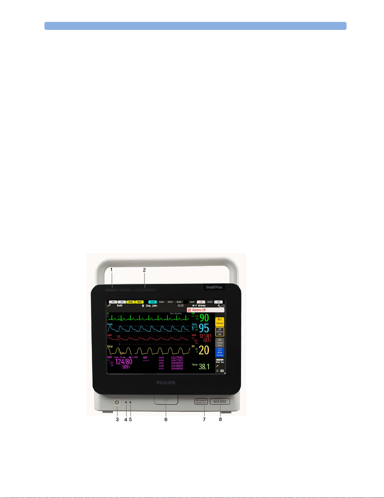
MX400/450/500/550
The MX400/450/500/550 monitors have the same parts, controls and indicators. Here the MX400 is
shown.
1 Color coded alarm lamps
2 Alarms Off lamp
3 Power on/Standby switch with
integrated LED: Green - On/
Standby, Red - Error
4 AC power LED
5 Battery LED
6 Mounting quick-release lever
(when this is pressed the
monitor is not fixed on the
mounting)
7 Service number and serial
number
8 Device type
17
1Introduction
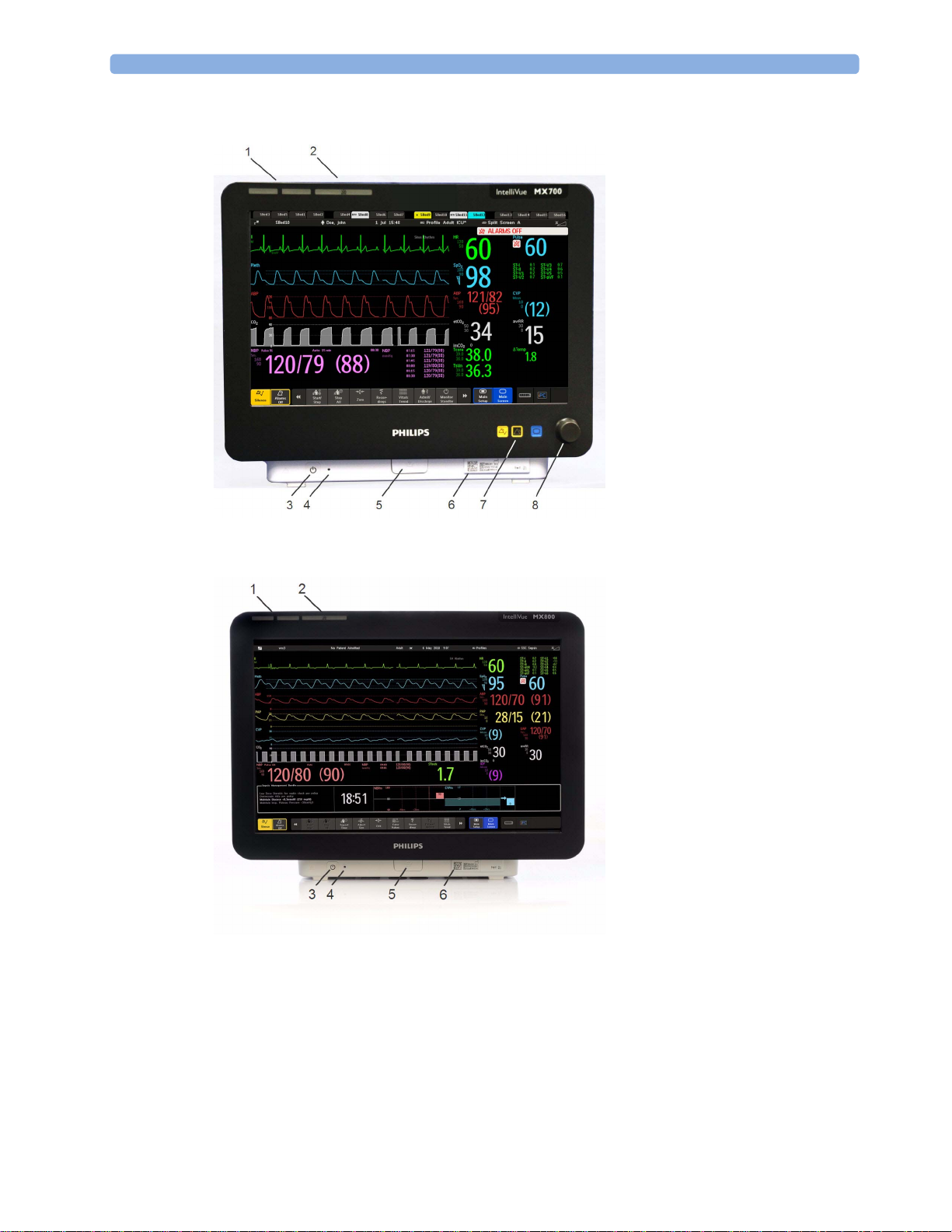
MX600/700
1 Color coded alarm lamps
2 Alarms Off lamp
3 Power on/Standby switch with
integrated LED: Green - On/
Standby, Red - Error
4 AC power LED
5 Mounting quick-release lever
(when this is pressed the
monitor is not fixed on the
mounting)
6 Part number and serial number
7 Hardkeys (Silence, Alarms Off,
Main Screen)
8 Navigation knob
MX800
1 Color coded alarm lamps
2 Alarms Off lamp
3 Power on/Standby switch with
4 AC power LED
5 Mounting quick-release lever
6 Part number and serial number
Devices for Acquiring Measurements
integrated LED: Green - On/
Standby, Red - Error
(when this is pressed the
monitor is not fixed on the
mounting)
18
The patient monitor acquires patient measurements using the devices described in this section. You
can also extend the measurement capabilities of your monitor with such devices. Of these
measurement devices, only the X2 has its own power on/standby switch, and can be powered from an
external power supply or a rechargeable battery when not directly connected to the monitor (refer to
the IntelliVue X2 Instructions for Use for details). All the rest take their power exclusively from the

monitor, and switch on automatically when you turn on the monitor. A green power-on LED indicates
when they are drawing power from the monitor. A permanently illuminated, or flashing, red LED
indicates a problem with the unit that requires the attention of qualified service personnel.
All symbols used on the front panels are explained in “Symbols” on page 445.
WARNING
When connecting devices for acquiring measurements, always position cables and tubing carefully to
avoid entanglement or potential strangulation.
Flexible Module Rack (M8048A)
1 Introduction
MX600/
MX700/
MX800
The 8-slot flexible module rack (FMS-8) lets you use up to eight plug-in physiological measurement
modules. For the MX800, you can connect two FMSs to use up to 10 measurement modules.
The maximum number of specific module types that can be used simultaneously in an FMS-8 is: five
pressure modules, four temperature modules, four VueLink or IntelliBridge modules (any
combination).
When two FMSs are used, in total a maximum of 10 pressure modules can be used.
Connect the FMS to the monitor via the measurement link cable (MSL). Use the MSL connector on
the left-hand side to connect an additional MMS. Use the connector on the right to connect to the
monitor.
4-Slot Flexible Module Rack (FMS-4)
1 X1 Multi-Measurement Module
2 Multi-Measurement Module
mount
3 Flexible Module Rack FMS-8
4 Power on LED
5 Interruption indicator
MX600/
MX700/
MX800
The 4-Slot flexible module rack (FMS-4) lets you use up to four plug-in physiological measurement
modules.
19

1Introduction
The maximum number of specific module types that can be used simultaneously in an FMS-4 is: four
pressure modules, four temperature modules, four VueLink or IntelliBridge modules (any
combination).
Connect the FMS to the monitor via the measurement link cable (MSL). Use the MSL connector on
the left-hand side (if you have the appropriate option) to connect an additional MMS. Use the
connector on the back to connect to the monitor.
Measurement Modules
MX500/
MX550
MX600/
MX700/
MX800
You can use up to three plug-in modules in the optional module slots. Available modules are:
• Invasive blood pressure (M1006B)
• Temperature (M1029A)
• Oxygen saturation of arterial blood (SpO
) (M1020B)
2
• Cardiac output (M1012A), and Continuous cardiac output with M1012A Option #C10
• Intravascular Oxygen Saturation - ScvO2 or SvO2 (M1011A)
• Spirometry (M1014A)
• EEG (M1027A)
• NMT (865383)
• IntelliBridge EC10 (865115)
• Recorder (M1116B/C)
You can use up to eight measurement modules with the Flexible Module Rack (M8048A). Available
modules are:
• Invasive blood pressure (M1006B)
• Temperature (M1029A)
• Oxygen saturation of arterial blood (SpO
) (M1020B)
2
• Cardiac output (M1012A), and Continuous cardiac output with M1012A Option #C10
MX500/550/
600/700/800
20
• Transcutaneous gas (M1018A)
• Mixed venous oxygen saturation - SvO
• Intravascular Oxygen Saturation - ScvO
(M1021A)
2
or SvO2 (M1011A)
2
• EEG (M1027A)
• Bispectral Index - BIS (M1034A)
• Spirometry (M1014A)
• NMT (865383)
• VueLink device interface (M1032A)
• IntelliBridge EC10 (865115)
• Recorder (M1116B/C)
You can plug in and unplug modules during monitoring. Insert the module until the lever on the
module clicks into place. Remove a module by pressing the lever upwards and pulling the module out.
A measurement automatically switches on when you plug the module in, and switches off when you

unplug it. Reconnecting a module to the same monitor restores its label and measurement settings,
such as alarms limits. If you connect it to a different monitor, the module remembers only its label.
The connector socket on the front of each module is the same color as the corresponding connector
plug on the transducer or patient cable.
Press the Setup key on the module's front to display the measurement's setup menu on the monitor
screen. When the setup menu is open, a light appears above the key. Some modules have a second key.
On the pressure module, for example, it initiates a zeroing procedure.
Example Module (SpO2)
MX500/550/
600/700/800
1 Introduction
1 Module name
2 Setup key LED
3 Setup key to enter setup menu of measurement modules or
external device data window. Some modules have a second
module-specific key next to this one, for example Zero.
4 Connector socket for patient cable/transducer
X1 Multi-Measurement Module (M3001A)
The X1 Multi-Measurement Module (MMS) can simultaneously monitor 3-, 5-, 6- or 10-lead ECG
(including arrhythmia and ST monitoring), respiration, SpO
temperature.
You can connect it to the monitor via a cable or mount it on the left side of the FMS.
, NBP and either invasive pressure or
2
21

1Introduction
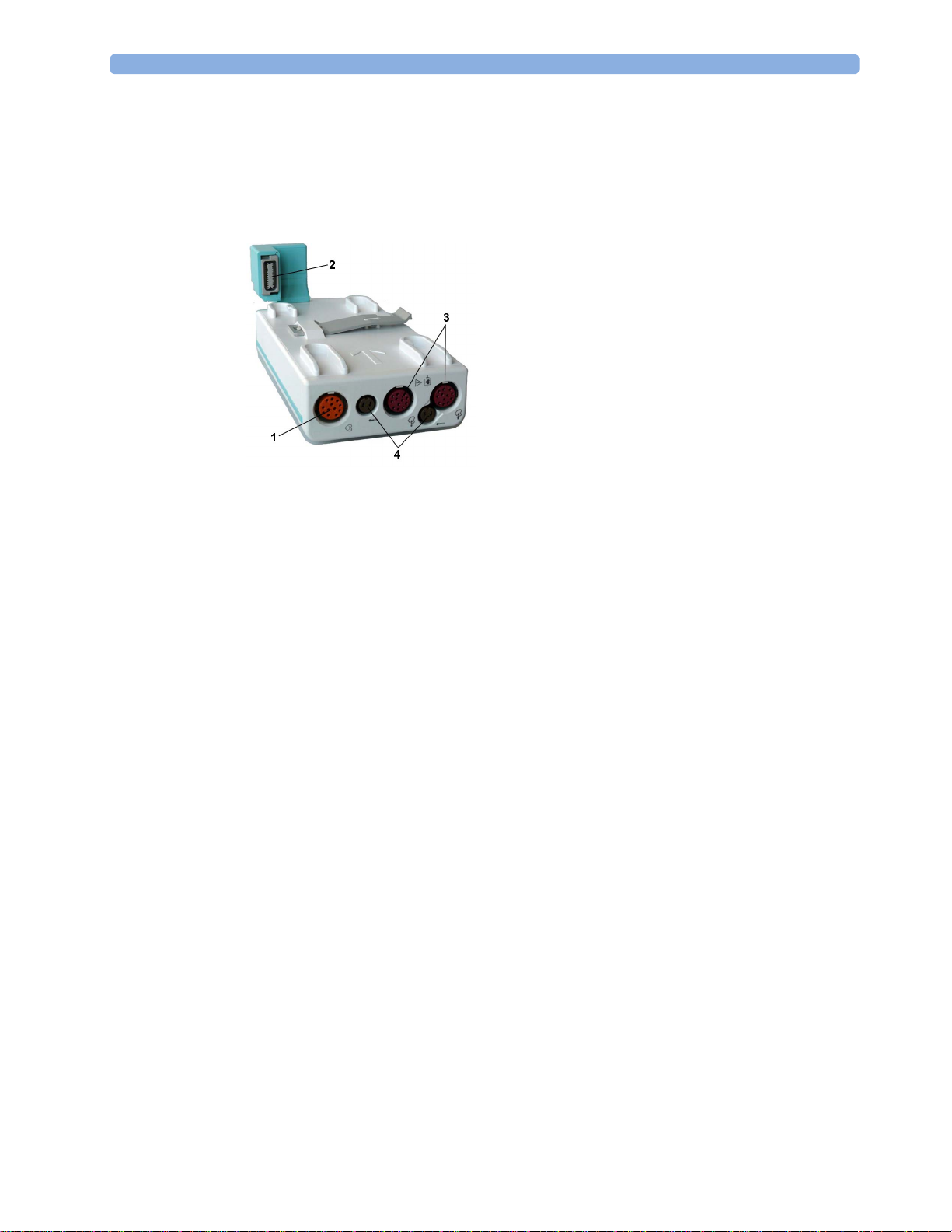
X1 Connectors and Symbols
1 White ECG/Resp connector
X2 Multi-Measurement Module (M3002A)
The X2 Multi-Measurement Module (MMS) can simultaneously monitor 3-, 5-, 6- or 10-lead ECG
(including arrhythmia and ST monitoring), respiration, SpO
temperature, or CO
The X2 has the added capability to operate as a stand-alone monitor, and can be powered by a
rechargeable battery. This makes it particularly suited to transport situations. When the X2 is
disconnected from the original host monitor, it continues to monitor the patient as a stand-alone
monitor running on battery power, eliminating the need for a separate transport monitor. When the
X2 is connected to a new host monitor, it resumes its role as MMS, ensuring fully continuous
monitoring. For details of using the X2 as a stand-alone monitor, refer to the IntelliVue X2
Instructions for Use.
. It has a color touchscreen display.
2
2 Blue SpO
3 Red NBP connector
4 Combined pressure (red) and temperature
connector
2
(brown) connector - connect either invasive
pressure transducer or temperature probe.
You might have a version of the MMS that
does not have this connector.
5 NBP STAT key - starts NBP STAT series
of measurements
or
Zero key - initiates a zero procedure for the
connected pressure transducer when
pressed and held for a second
6 NBP Start/Stop key - starts or stops NBP
measurements
7 Silence: acknowledges all active alarms by
switching off audible alarm indicators and
lamps
, NBP and either invasive pressure and
2
22
When connected to a host monitor (
Companion Mode is indicated), the X2 takes power from the
host, including that required for battery charging. The X2 can also be powered by AC mains when not
connected to a host monitor using the optionally available external power supply (M8023A). See the
IntelliVue X2 Instructions for Use for details.
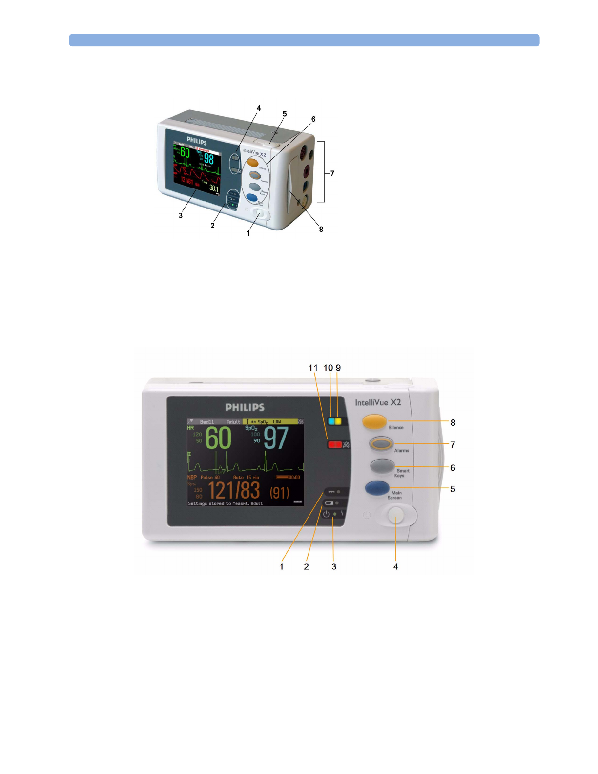
X2 Overview
1 Introduction
1 On/Standby switch
2 Power and battery indicators (see “X2
Controls and Indicators” on page 23)
3 3.5-inch TFT LCD touchscreen QVGA
display
4 Alarm lamps (see “X2 Controls and
Indicators” on page 23)
5 Battery eject button
6 Hard keys (see “X2 Controls and
Indicators” on page 23)
7 Measurement connectors (see “X2 Patient
Connectors, Right Side” on page 24)
8 Battery compartment
X2 Controls and Indicators
1 External power LED. Green when monitor is powered from an external power source.
2 Battery status LED. Yellow when charging. Flashing red when battery is empty.
3 On/Standby LED. Green when monitor is on. Red indicates an error.
4 On/Standby switch. Disabled when X2 is connected to a host monitor
5 Main Screen key: closes all open menus/windows and returns to the main screen.
6 SmartKeys key: brings up SmartKeys on the screen.
7 Alarms key: turns alarms On/Off, or pauses them.
23

1Introduction
8
Silence key
9 Active alarm lamp. Red or yellow, depending on alarm level. Blinks until active alarm is
acknowledged.
10 Active INOP alarm lamp in light blue. Blinks until active INOP is acknowledged.
11 Alarms off indicator. When alarms are suspended, the lamp is red (or yellow when yellow alarms
are suspended), and the alarms off symbol is shown.
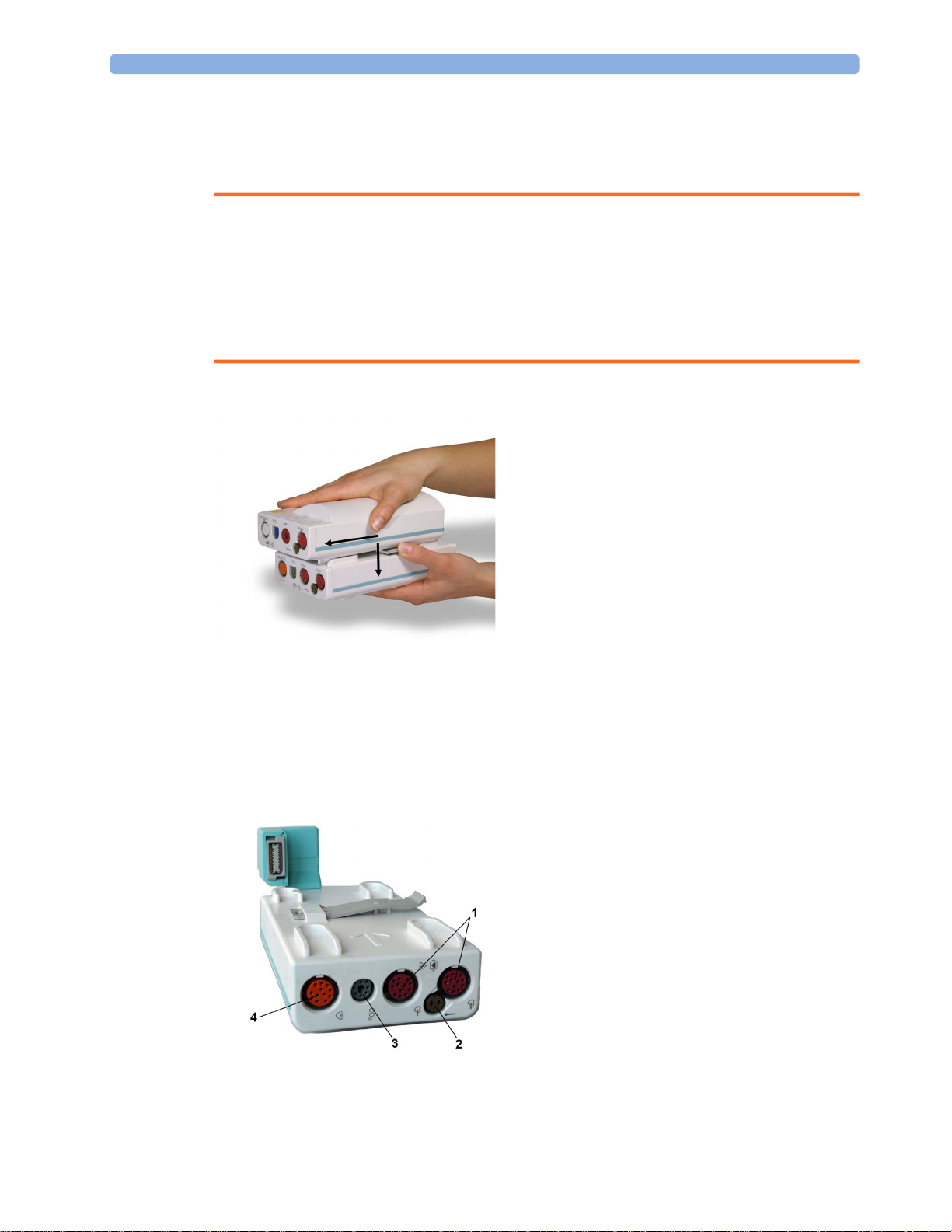
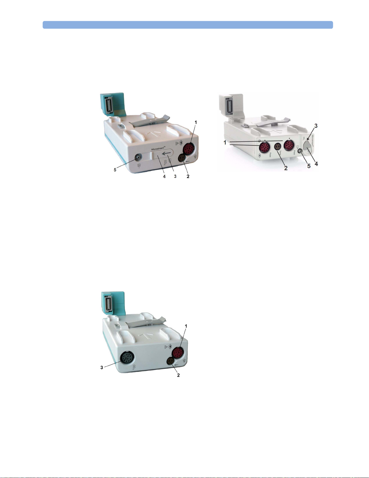
X2 Patient Connectors, Right Side
1 Pressure (option)
2 Temperature (option)
3 Noninvasive blood pressure
X2 Left Side
4 SpO
5 ECG sync pulse output
6 ECG/Respiration
7 CO
2
(option in place of
2
Pressure and Temperature)
1 Loudspeaker
2 MSL Connector. Connects to the external power
supply or a host monitor via the MSL cable for AC
mains operation, battery charging, and
communication with a network.
24
MMS Extensions
The MMS extensions connect to the X1 and X2 MMS and use the MMS settings and power. Trend
data and measurement settings from the measurements in the extensions are stored in the MMS.
WARNING
• The MMS extensions can only function when they are connected to an MMS. If the MMS is
removed during monitoring, the measurements from both the MMS and the extension are lost.
• Measurements from an MMS extension connected to an X2 are not available when the X2 is
running on its own battery power. They are only available when the X2 is powered from AC mains,
when connected to a host monitor or the external power supply (M8023A), or from the Battery
Extension.
To separate an extension from the MMS, press the release lever down, and push the MMS forward.
1 Introduction
M3014A, M3015A, M3015B and M3016A Capnography MMS Extensions
The optional M3014A Capnography extension adds mainstream capnography or sidestream
capnography, and optionally one pressure plus either a pressure or a temperature, Cardiac Output and
Continuous Cardiac Output to the MMS.
M3014A
1 Pressure connectors (red)
2 Temperature connector (brown)
3 Mainstream/sidestream connector CO
4 Cardiac Output connector
2
25
1Introduction
The optional M3015A Microstream CO2 extension adds microstream capnography and optionally
either pressure or temperature to the MMS. The optional M3015B Microstream CO
microstream capnography, two pressures and a temperature to the MMS.
M3015A M3015B
1 Pressure connectors (red) - M3015A optional
extension adds
2
MX600/700/
800
2 Temperature connector (brown) - M3015A optional
3 Inlet
4 Microstream connector CO
5 Gas sample outlet
2
The optional M3016A Mainstream CO2 extension adds mainstream capnography and optionally either
pressure or temperature to the MMS.
M3016A
1 Pressure connector (red)
2 Temperature connector (brown)
3 Mainstream/sidestream connector CO
2
(optional)
26
When a capnography extension is connected to an X2 MMS with CO
will be automatically deactivated in favor of the one in the X2. If you prefer to use the CO
, the CO2 from the extension
2
2
measurement on the extension, you can activate it via the measurement selection key (see “Resolving
Label Conflicts” on page 44).
The cardiac output measurement in the M3014A is deactivated when the extension is used with an X2
MMS, even if the X2 is connected to an external power supply. The cardiac output measurement is
only available when the X2 is connected to a host monitor.
M3012A Hemodynamic MMS Extension
The M3012A Hemodynamic extension can be connected to the M3001A Multi-Measurement Module
to provide the following additional measurements: Temperature, Pressure, an additional Pressure or
Temperature, and C.O. and CCO measurements.
1 Introduction
1 Cardiac Output (orange; optional)
2 Connection to MMS
3 Pressure connectors (red)
4 Temperature connectors (brown)
The cardiac output measurement is deactivated when the extension is used with an X2 MMS unless the
X2 is connected to a host monitor.
Using MMSs in a Mixed Software Environment
When an MMS is used with monitors having different software revisions, be aware that functionality
set up in a monitor with a newer revision will disappear when the MMS is connected to a monitor with
an older revision without that functionality. For example, if an X2 is used with a revision H monitor
and has been set up to alarm on Afib, this alarm will no longer exist when the X2 is connected to a
revision G monitor. If you work in a mixed software environment, inform yourself about the
differences between revisions by referring to the What's New chapter.
Operating and Navigating
Everything you need to operate the monitor is contained on its screen. Almost every element on the
screen is interactive. Screen elements include measurement numerics, waveforms, screen keys,
information fields, alarms fields and menus. The typical operator's position is in front of the monitor.
The configurability of the monitor means that often you can access the same element in different ways.
For example, you might be able to access an item through its on-screen setup menu, via a hard key, or
via a SmartKey.
27
1Introduction
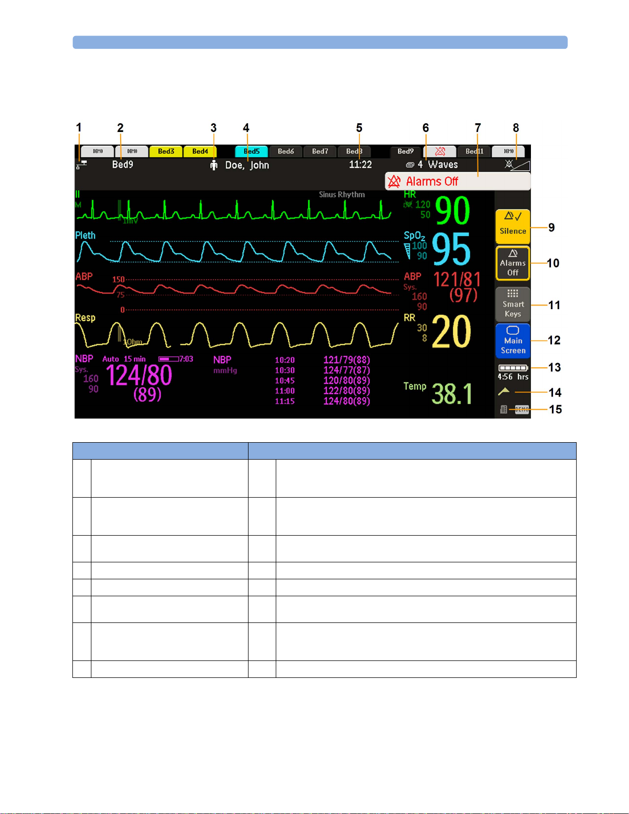
MX400
On the MX400, the permanent keys and the key to access the SmartKeys are on the right of the screen.
Monitor information line Other screen elements
network connection indicator
1
(documented in Troubleshooting in the
Service Guide)
bed label - gives access to Equipment
2
window
patient category symbol
3
patient name
4
date and time
5
current screen name/enter Change Screen
6
menu
alarm status area - shows active alarm
7
messages or Alarms Off symbol when
alarms are switched off
alarms off/alarm volume indicator
8
Silence - acknowledges all active alarms by switching off audible alarm indicators
9
and lamps permanently or temporarily, if alarm reminder (ReAlarm) is configured
on.
Pause Alarms or Alarms Off - stops alarms being announced for a set time or
10
switches them off. Select again to immediately switch alarms on again. Can be
configured not to appear here.
SmartKeys -displays a block of SmartKeys. These change according to your
11
monitor's configuration
close all open menus and windows and return to main screen
12
battery indicator with remaining battery time
13
status messages indicator - clicking this area displays any pending status messages
14
measurement selection symbol - opens Measurement Selection window to resolve
15
label conflicts
28
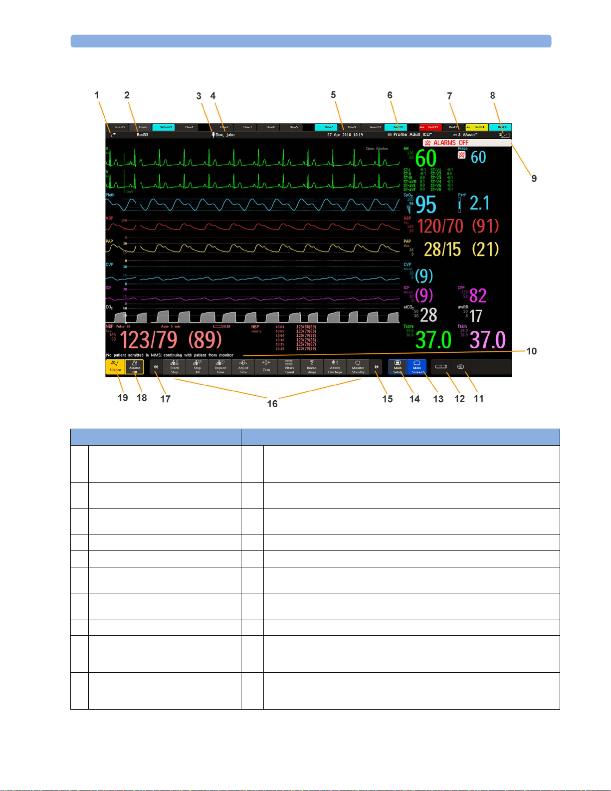
MX450/500/550/600/700/800
1 Introduction
Monitor information line Other screen elements
network connection indicator
1
(documented in Troubleshooting in the
Service Guide)
bed label - gives access to Equipment
2
window
patient category symbol
3
patient name
4
date and time
5
access the Profiles menu or Profile
6
name, depending on configuration
current screen name/enter Change
7
Screen menu
adjust alarm volume/level indicator
8
alarm status area - shows active alarm
9
messages or Alarms Off symbol when
alarms are switched off
The status line shows messages with information and prompts you for possible
10
actions (MX400/450/500/550 do not have a reserved space for this feature).
remote application symbol or iPC symbol (MX600/700/800 only)
11
measurement selection symbol - opens Measurement Selection window to
12
resolve label conflicts
close all open menus and windows and return to main screen
13
enter Main Setup menu
14
scroll right to display more SmartKeys
15
SmartKeys - these change according to your monitor's configuration
16
scroll left to display more SmartKeys
17
Pause Alarms or Alarms Off - stops alarms being announced for a set time or
18
switches them off. Select again to immediately switch alarms on again. Can be
configured not to appear here.
Silence - acknowledges all active alarms by switching off audible alarm indicators
19
and lamps permanently or temporarily, if alarm reminder (ReAlarm) is configured
on.
29

1Introduction
Selecting Screen Elements
Select a screen element to tell the monitor to carry out the actions linked to the element. For example,
select the Patient Identification element to call up the
HR numeric to call up the
menu.
Note that the space between each line of a menu may be configured to wide or narrow to facilitate
your most common method of operation, either touch, remote control or a pointing device such as a
mouse.
Setup ECG menu. Select the ECG wave segment to call up the ECG Lead
Using the Touchscreen
Select screen elements by pressing them directly on the monitor's screen.
Disabling Touchscreen Operation
To temporarily disable touchscreen operation of the monitor, press and hold the Main Screen
permanent key. A padlock will appear on the
Patient Demographics window, or select the
Main Screen permanent key.
Press and hold the Main Screen permanent key again to re-enable the touchscreen operation.
Using a Mouse or Trackball
If you are using a mouse or trackball, select screen elements by clicking on them (press and release the
left mouse button). While you are moving the mouse, a cursor appears and a highlight shows your
current position.
Moving Windows
You can move windows and menus using the Touchscreen or a mouse. To move a window,
1 Select the title of the window and keep your finger on the title, or the mouse button pressed.
2 Move your finger on the Touchscreen, or move the mouse, to move the window.
3 Take your finger off the screen, or release the mouse button, to place the window in the final
position.
The new position is only active until the window or menu is closed. Not all locations on the screen can
be a target position, a window cannot overlap the monitor info line, the alarms and INOPs or the
status line.
Using Keys
The monitor has four different types of keys:
Permanent Keys
A permanent key is a graphical key that remains on the screen all the time to give you fast access to
functions.
30
 Loading...