

Page 1
Published by GE 9845 Monitor Service Dept. Printed in Italy © Copyright reserved Subject to modification
3119 206 13832
H
GB
USER MANUAL
MGD203
MGD403
Page 2
I FCC NOTICE - COPYRIGHT
FCC NOTICE
This equipment has been tested and found to comply with
the limits for a Class A digital device, pursuant to part 15
of the FCC (U.S. Federal Communications Commission)
rules. These limits are designed to provide reasonable
protection against harmful interference when the
equipment is operated in a commercial environment.
This equipment generates, uses and can radiate radio
frequency energy and , if not installed and used in
accordance with the instruction, may cause harmful
interference to radio communications.
Operation of this equipment in a residential area is likely
to cause harmful interference in which case the user will
be required to correct the interference at his own expense.
The monitor described in this user manual has been
certified/registered by the safety agencies/regulatory
authorities as model n° MD0709BRM.
Modification
The FCC requires the user to be notified that any changes
or modifications made to this device that are not expressly
approved by the manufacturer may void the user’s
authority to operate the equipment.
Cables
Connections to this device must be made with shielded
signals cables with metallic RFI/EMI connector hoods to
maintain compliance with FCC Rules and Regulations.
The lighting flash with arrowhead symbol is intended
to alert the user of the presence of uninsulated “dangerous
voltage” within the product’s enclosure that may be sufficient magnitude to constitute a risk of electric shock to
people.
The exclamation mark is intended to alert the user of
the presence of important operating and maintenance
(servicing) instructions in literature accompanying the
appliance.
CAUTION: TO REDUCE THE RISK OF ELECTRICAL SHOCK,
DO NOT REMOVE COVER (OR BACK)
NO USER SERVICEABLE PARTS INSIDE
REFER SERVICING TO QUALIFIED SERVICE PERSONNEL
CAUTION
RISK OF ELECTRICAL SHOCK
DO NOT OPEN
ATTENTION
RISQUE DE CHOC ELECTRIQUE
NE PAS OUVRIR
WARNING:
TO PREVENT DAMAGE WHICH MAY RESULT
IN FIRE OR SHOCK HAZARD, DO NOT
EXPOSE THIS APPLIANCE TO RAIN OR
EXCESSIVE MOISTURE.
Page 3

COPYRIGHT - CE II
Copyright ©
This manual is copyrighted with all rights reserved. Under
the copyrights law, this manual may not be copied in
whole or part, without written consent. Under the law,
copying includes translating into another language or
format.
Apple, Macintosh/II, PowerMacintosh, Apple Quadra,
Centris and Power Mac are trademark of Apple Computer
Inc.
IBM, IBM PC/XT, PC/AT, PS2 (Personal Sytem/2) , VGA
(Video Graphics Array) , OS/2 and DOS are registered
trademarks of International Business Machines
Corporation.
386, 386SX, 486 and Pentium are registered trademarks
of Intel Corporation.
SunSparc station is a registered trademark of Sun
Microsystems.
Windows and Windows ‘95 are a registered trademark of
Microsoft Corporation.
DDC is trademark owned by the Video Electronics
Standards Associations.
All other trademarks and registered trademarks are the
sole property of their respective companies or
organisation.
Cyberscreen ® monitor is a Philips technology
Printed in Italy
The manufacturer declares that this product
satisfies the basic requirements of Electromagnetic
Compatibility and Safety of the Directive:
- 93/42/EEC Medical Device regarding risk Class I
device.
- As having been designed and tested in conformity with
the requirements of the following Reference Standards:
- EN55011 - Limits and methods of measurements of
radio interference characteristics of Industrial Scientific
and Medical (ISM) radio-frequency equipment; Class B
- EN60601-1-2 (1993) Medical electrical equipment -
Part 1: General requirements for Safety - 2 - Collateral
Standard: Electromagnetic compatibility Requirements and tests.
- EN60601-1 Medical electrical equipment - Part 1:
General requirements for Safety.
- EN60950 (Safety of Information Technology equipment,
including electrical business equipment).
Conformity with the above basic requirements is certified
by means of the CE Marking shown on the product.
Page 4

1 ENGLISH
TABLE OF CONTENTS
PREFACE 2
INTRODUCTION 2 - 3
MAIN FEATURES 4 - 5
SETTING UP YOUR NEW MONITOR 6 - 9
Inspection and unpacking 6
Connecting your monitor 7 - 9
INFORMATION AND USE OF THE CONTROL PANEL
Control location and functions 10
HARDWARE OSD
Adjustment: size position, geometry and special
functions 11 - 22
Technical Specification APPENDIX 1
Mechanical Specification APPENDIX 2
Note for UK APPENDIX 3
Factory Pre-Set Video Timings APPENDIX 4
Page 5

ENGLISH 2
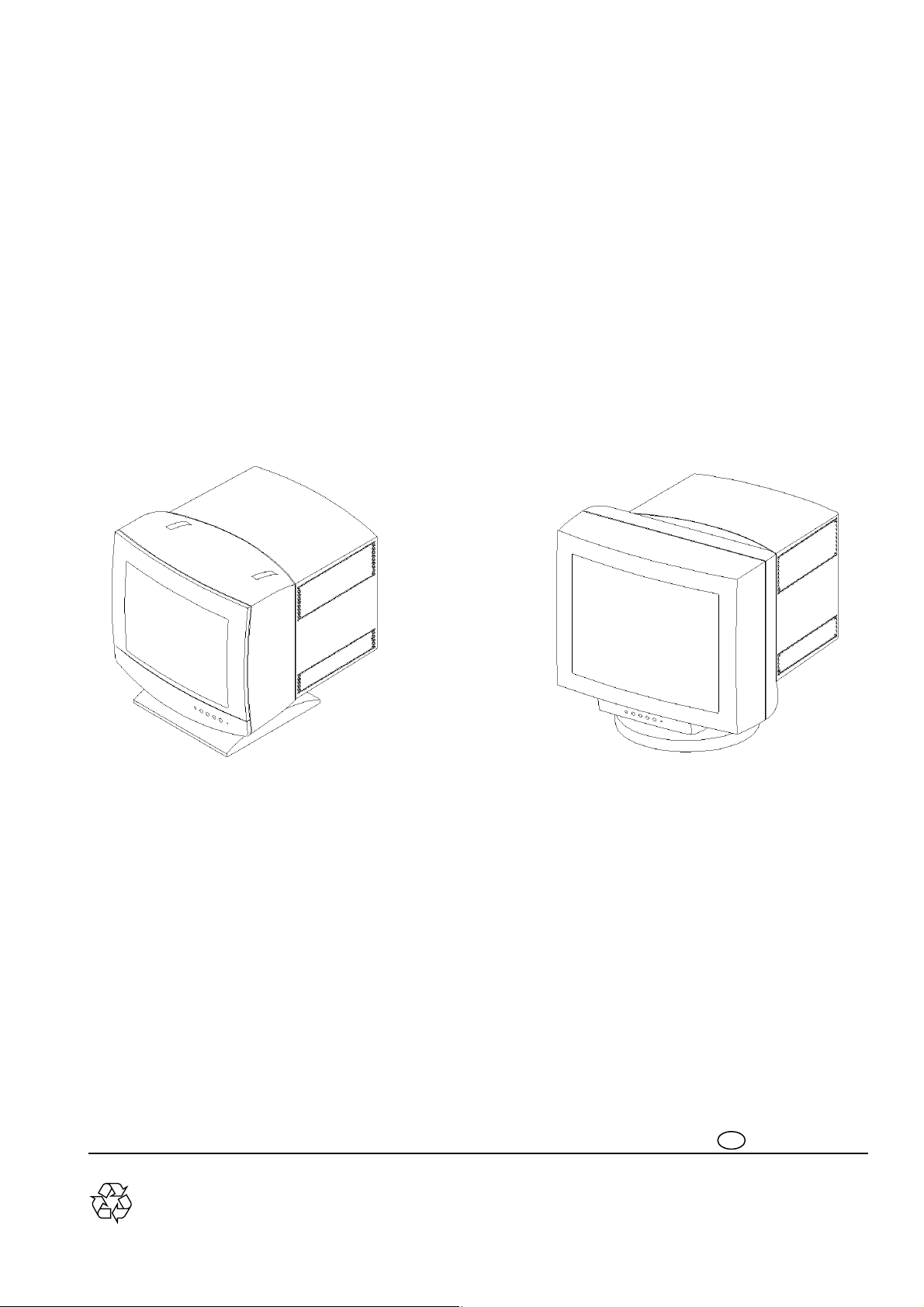
Thank you for purchasing the new MGD 203/MGD 403 high brightness monochrome
monitor. We hope you will enjoy using it and we are confident that this quality product will
meet your highest expectations.
This user manual contains the following informations:
‘ An introduction to the product features
‘ Instructions for unpacking and connecting to a computer: this allows you to quickly set-
up and receive the best performance from your new monitor
‘ Guide to the On Screen Display
‘ Instructions for the care and maintenance of the monitor to extend its service life
‘ Trouble shooting information in case you encounter any difficulties while you are
installing or using the monitor
‘ Technical performance
PREFACE
Page 6

3 ENGLISH
The new MGD 203/MGD 403 is a very high brightness, high resolution digitally controlled
autoscan monochrome monitor, based on the CyberScreen technology. ®
This new monitor, specifically designed for medical applications, gives unique performances
in term of brightness, resolution and spot size.
Typical applications are X-ray display systems, Tele Radiology (TR), Picture Archiving and
Communications Systems (PACS), Radiology Information Systems (R.I.S.)
Cardiac Workstation, etc.
A rich set of functions allows quick installation, flexible user preference customization and
easy maintenance.
Specifically designed for very high-end medical imaging applications, the new MGD 203/ MGD
403 monitor is capable of working with all the formats available from the most
different monochrome as well as color video cards of both Apple and PC environments
and from all the high-end workstations.
This monitor incorporates a DDC1/DDC2B function that allows bidirectional communications
between the monitor and PC system for optimal video configuration.
It is also possible to use up to 15 of these monitors in Daisy Chain Mode, as explained later
in this manual.
Almost all the internal functions of the monitor are digitally controlled, and they can be stored
in a resident memory which may contain up to 28 different formats, 12 of which are factory preset. The monitor can store also five different ref. settings (all user adjustable) wich can be
recalled at any moment.
The power saving is operating ONLY when used with VESA DPMS compliant PC’s and/or
video controllers. By reducing power consumption to less than 15 W in suspend or standby mode and about 3 W in off mode, the monitor also complies with the Energy Star
Computers Program initiated by the EPA.
INTRODUCTION
Page 7

ENGLISH 4
The monitor will automatically sychronise within a wide range of scanning frequencies and
determine the specific operating mode.
Monitor behaviour (degauss & reset), image quality and screen geometry adjustments can
be changed or selected via the hardware OSD by means of the front panel push-buttons.
Your new monitor provides special features as:
´ Very high contrast, high definition image.
´ Digital brightness uniformity control (higher than 90%).
´ Automatic correction of the effect of the horizontal magnetic field.
´ Digital correction of geometric distortions.
´ Automatic calibration (with optional light probe and software tool).
´ Incredible high contrast (750 cd/sqm for 21” - 900 cd/sqm for the 17”).
´ Universal power supply.
´ Interactive On Screen Display with a rich set of functions for easy installation and cus-
tomization.
´ Fully autoscan from 30 to 95 KHz (Horizontal Frequency)
50 to 170 Hz (Vertical Frequency).
´ Most common video modes already factory stored in the monitor memory.
´ Large number of free memory locations to store up to 16 user-defined video modes.
´ Full compatibily with all mono and color video cards, progressive and interlaced timing
´ Black Level Stabilization for quick warm-up (4 min.) and perfect contrast stability over
time.
´ Integrated Ambient Light Compensation control function.
´ RS 485 - like ’Daisy chain’ bus connection (up to 15 monitors), allows simultaneous
adjustment of each enabled monitor from each monitor’s keyboard.
´ RS 232 serial connection to host computer or service laptop.
´ Large number of functions available through the interactive On Screen
Display, (including also Hours of Operating, Horizontal Scan Rate,
Vertical Refresh Rate) to allow easy installation and optimal operation.
´ Orbiting function to increase CRT lifetime.
´ Loop-through input facility makes the connection of more monitors to the same video
source easy and economical.
´ Flexible inputs selection: 3 BNCs (for mono drivers), 5 BNCs or 15 pin D-sub (for color
drivers).
´ Six user selectable combinations of max Brightness and max Contrast
(5 preset + 1 available to the user).
´ Direct key access for most commonly used user commands:
BRIGHTNESS up/down, CONTRAST up/down, REF. SETTING,
USER SETTING, USER STORE, KEYBOARD UNLOCK.
´ Automatic Brightess Control programmable.
´ Multi-level Keyboard lock facility.
´ Number of hours of operation recorded and readable at any time.
´ Power Saving (VESA DPMS) function according to latest Environmental
Regulations & Reccomendations, including also the Power Factor (IEC 555-2) control circuit.
Page 8

5 ENGLISH
ADVANCED TECHNOLOGY
The MGD 203/MGD 403 monitor includes the following advanced technologies:
- CYBERSCREEN®: digital technology that allows the optimization of the picture quality
all over the screen, corners included.
- MAGNETOMETER: the magnetic field inside your monitor may dramatically change
whenever you tilt or swivel the monitor, or when you bring a magnetic object, e.g. an audio
speaker, close to the monitor. Changes to the magnetic field around a monitor can cause
distortion of the image displayed on the screen. The automatic magnetic field compensation
circuitry (horizontal component of earth magnetic field) of your MGD 203/
MGD 403 monitor, immediately correct these effects thus keeping the image always sharp.
- ABC: Automatic Brightness Control (ABC) function, when enabled, adjusts automatically Brightness and Contrast according to the ambient light.
- Black Level Stabilization: The circuit reduces the time necessary to have a stabilized
brightness level from 20 minutes to less than 4 minutes. The BLS circuit also automatically
compensates the normal brightness decay due to the aging of the CRT.
- Digital Brightness Uniformity: thanks to the CyberScreen Technology, the screen
brightness can be digitally controlled all over the screen, making possible to have a >90%
brightness uniformity.
- Digital Control: all the monitor parameters, and display functions are accessible either
via the Service Software package or by means of a set of direct commands, making it easy
to remotly control the unit either from the System Console or from the Application
Program.
- Digital Geometry Control:
Full digital control of all geometry parameters to improve
the overall performances (geometry up to 1% - linearity up to 5%)
- Brightness Calibrator:
The optional MAP 201 HW/SW tool allows you to recalibrate the unit and to even
improve the brightness uniformity of the image all other the screen.
- Input Connection:
Your new monitor can be operated either through the 3 (5) BNC input or via the 15
pin mini D-sub inputs to give you the maximum flexibility.
AGAS
The CRT of your new MGD203/MGD403 is finished with “AGAS” treatment, one of the most
effective Anti-Glare/Anti-Static screen coating. With this treatment the intensity of reflected
light is reduced to less than 0,5%, the picture contrast and sharpness remains unimpaired,
and cleaning the screen is made easier.
MAIN FEATURES
Page 9

ENGLISH 6
AUTOSCAN
This feature allows you to use your monitor with a wide range of video cards: the MGD
203/MGD 403 monitor will automatically synchronize at all horizontal frequencies in the
range 30 - 95 KHz and vertical frequencies in the range 50-170 Hz, and will automatically discriminate the specific operating mode.
CATHODE RAY TUBE
This new monitor incorporates a special monochrome 17”/21” CRT for brilliant and high
contrast image (approximately three times the brightness of a standard monochrome
CRT). The Flat Square screen has P45 phosphor for best performance, high resolution inline electron polygon DAF (Dynamic Astigmatism and Focusing) triple gun and AGAS
coating.
DDC (DISPLAY DATA CHANNEL)
This feature allows your operating system and application software to retrieve the display
identity information directly from the display device.
Note: the DDC feature works only if the monitor is connected to the PC by a mini D-Sub
15 pins / mini D-Sub 15 pins video signal cable as explained in the chapter Connecting
your monitor’ .
ENVIRONMENT
All the package materials are recyclable. This monitor does not contain any:
Polychlorinated Biphenyl (PCB), Polyc. Diphenylether (PCDE), Polybromated
Diphenylether (PBDE), Asbestos and Cadmium.
The complete manufacturing process of the monitor does not emit the following substances: Chlorinated Fluorohydrocarbons (CFC), Acrylonitrile, Styrol, Phenol, Benzol and
Heavy Metals.
HARDWARE OSD (ON SCREEN DISPLAY)
An easy to use OSD menu allows the user to control and adjust some monitor parameters: Tilt, Hor. & Vert. Phase, Hor. and Vert. Size.
Plug
and
Play
Page 10

7 ENGLISH
1GUN / 3 GUNS BRIGHTNESS
This function allows to select (via OSD menu) between Low Brigtness Mode (even better
picture sharpness and reduced eye strain) and High Brightness Mode (full brightness).
WARNING: This function is available only if “1-BNC” input is selected since it has no much
sence with color video cards.
MAP 201 - Calibration Package (optional)
Specifically designed for the Triple Gun monochrome monitor series, this package consists of a calibration software and an high sensitivity light probe sensor.
The calibration package allows precise calibration of: brightness uniformity across the
entire area, black level and white level, moreover it allows the user to correct the beam
convergence from edge to edge for optimum display sharpness and accuracy.
ORBITING
The MGD 203/MGD 403 monitor includes a circuit specifically developed to increase the
Cathode Ray Tube phosphors life-time by slightly moving, on a circular orbit, the entire displayed image.
DAISY CHAIN INTERFACE
The two 9-pin DSUB (male and female) connectors are parallel-wired RS485-like MultiPoint Serial Interface to allow the connection of up to 15 units in daisy chained configuration, each one having unique address in the range from 1 to 15.
The maximum total cable lenght between monitors is 15 m.
If Daisy Chain Mode is ENABLED the RS232, KEYBOARD and ABC controls are trasmitted to all the other monitors and at the same time executed inside the monitors.
(see specific chapter for details)
AUTOMATIC BRIGHTNESS CONTROL
The ABC feauture automatically adapts the contrast/brightness level to the ambient light
(measured with a special sensor).
The ABC function is selectable in one of the following three modes:
Active control range : 10 - 1000 lux ambient on the photo-sensor
ABC - FULL Adjustable Reduction Effect via OSD (20% - 100%)
ABC - REDUCTION Derived from ABC - FULL
ABC - OFF No reduction (100%)
In case of daisy chain connection only one unit can be allowed to be “ABC master” (flying master concept). See also pages 18 and 25 of this user manual.
SHOW CONFIGURATION
Via OSD it is possible to display the monitor unit information:
firmware release, total working hours (to keep track of the real usage of the monitor),
active video mode, horizontal and vertical frequencies.
Page 11

ENGLISH 8
Note:
REFERENCE SETTING
Five different ‘pairs’of brightness and contrast combinations can be defined, and stored
in the monitor and selected via OSD menu. This feature is particularly attractive for
OEMs using the monitor with multiple systems wich will save a lot of time in the factory and in the field as well (‘tailoring’ of the monitor adjustments on the specific system
is no more needed).
POWER MANAGEMENT
The MGD 203/MGD 403 is ENERGY STAR compatible (requires “VESA DPMS”
compliant signalling).
The Power Management feature operates automatically by gradually powering down
the monitor in three different status:
ON: Display in full operation (GREEN/YELLOW/RED)
depending on reference setting status - see also’ LED
LIGHT MEANING TABLE’.
SUSPEND OR STAND-BY: Either Hsync or Vsync is missing, the power con sum-
ption is less than 15 W, (Yellow blinking LED).
OFF: Both H & V signals are inactive, the power consum-
ption is about 3 W, LED off).
This function can be easily disabled in a safe and permanent way through the Hardware
OSD (Mode/Power Saver).
The manufacturer is a partner in the EPA’s Energy Star computer program.
The Energy Star emblem does not represent EPA endorsement of any product or service.
PRE-SET MODES
The monitor memory can store the geometry display parameters of each operating
mode up to 28 modes (12 of them are factory pre-set; see appendix 4), thus allowing
to auto-size the picture for the detected mode.
For any “not found” mode, the microprocessor will automatically store the geometry settings as adjusted by the user in the first free location.
The user has the possibility to change the adjustments at any time.
RESOLUTION
The maximum resolutions displayable on the screen are:
MGD203 : 1280 x 1024 @ 90 Hz
MGD403 : 1600 x 1280 @ 72 Hz
UNIVERSAL POWER SUPPLY
This unit will automatically detect and power up at any line voltage and frequency all
over the world with no intervention of the operator.
Page 12

9 ENGLISH
Before installation, please check your monitor for physical damages which may have
occurred during transport, and also check that the package includes all the items below:
´ Your new monitor (including pedestal)
´ Power cord
´ User manual
´ Signal cable (optional)
In case any items are missing or damaged, please contact your dealer or supplier.
This chapter explains in detail how to safely unpack and position your new display:
Caution: please remember that your monitor weights approximately:
MGD 203 24 Kg (52.9 lbs);
MGD 403 32 Kg (70.5 lbs);
therefore to avoid injury, you should not lift it by yourself: two people are required.
1. To safely lift the monitor, position one hand below the top front mask and the other
one below the bottom of the backcover.
2. Place the monitor only on a strong table or a desk. Avoid placing your monitor on
top of a computer.
To minimise glare and reduce eye fatigue, it is recommended to place your monitor in the
following positions:
´ avoid direct sunlight or other bright light source;
´ keep the screen lower than your eyes (with an angle of 20° respect to the ideal
horizontal line;
´ set the monitor to ”1 gun mode”, when full brightness is not required;
Retain your original packing, which is ideal and safe, in case you need to transport
your monitor in the future.
The MGD 203/MGD 403 monitor is equipped with a tilt swivel base which will allow you to
position the display at a comfortable viewing angle.
The base rotates 140° to the right and to the left (a stop prevents further rotation) and 5°
top / forward plus 15° top / backwards.
A duly designed metal bracket is also available as option for both MGD203 and MGD403
when a ceiling or trolley mount application is requested.
INSPECTION
UNPACKING
Suggestions !
Important !
Page 13

ENGLISH 10
Follow these steps to connect the MGD 203/MGD 403 monitor to your computer:
This monitor is equipped with a standard European or North American or United Kingdom
power cord provided with ground wire (depending on where your monitor has been purchased). According to the AC power standards utilised in your Country, you may be
required to purchase a different power cord.
THE SOCKET OUTLET TO WHICH THE UNIT IS CONNECTED SHALL BE INST ALLED
NEAR THE EQUIPMENT AND SHALL BE EASILY RECOGNIZABLE AND ACCESSIBLE AND/OR THE POWER LINE SHALL BE PROVIDED WITH AN EASILY RECOGNIZABLE CIRCUIT BREAKER.
- Connect the monitor to a grounded outlet.
- This equipment can be connected to an IT power system with phase voltage of
230 VAC.
POWER LED COLOUR
In X-ray systems context, the red light indicates that the system is not working with optimal Image Quality; user could work in a hazardous condition. Press both + and - ref. keys
contemporary; LED light turns green, and the optimal Image Quality shall be restored.
CONNECTING YOUR
MONITOR
Connection to the mains
Warning !
!
Important !
figure 1
1. Remove the connector protection from the rear cover.
2. Connect the female plug of the power cord to the
mainssocket on the back of the monitor (see figure 1).
3. Connect securely the male plug of the power cord to the AC
power supply outlet.
All the world AC power voltages (100 - 240 Vac) and frequencies will be automatically selected. You do not need to check
the voltage or change any fuses.
Important !
Please, be sure the AC power of your computer or any one
else in the chain (if Daisy Chain mode is used) is ‘OFF’
before connecting any display peripheral. You may cause
serious personal injury as well as permanent damage to
your computer equipments.
Warning !
!
End of life disposal
Your new set contains materials which can be recycled and reused. Specialized companies can recycle your product to increase the amount of reusable materials and to minimize the amount of material to be disposed of.
Please, inform yourself on local regulations on disposal of your old set.
Page 14

11 ENGLISH
figure 2
Connection to the computer
1. Connect the male plug of the mini D-Sub 15 pins cable (optional) to the D-SUB
input connector at the rear of the monitor (see figure 2).
2. (Alternative) Connect the BNC connectors (VIDEO/H/V) of the video cable to
thesocket on the back of the monitor as shown in figure 3. In this configuration,
the three guns will be automatically ‘locked’ (the monitor is driven as ‘monochrome’).
3. (Alternative) Connect the BNC connectors (R/G/B/H/V) of the video cable to the
socket as in § 2. (see figure 4). In this configuration, the guns are driven indepentently (the monitor is seen as ‘colour’).
4. If you use some monitors in Daisy Chain configuration, the units shall be connected each other as shown in figure 5.
5. Connect the other end of the video cable to the VIDEO OUTPUT of your PC (with
high resolution graphic card or usual VGA graphic card).
Note: The monitor automatically recognizes the connected input.
The 15 pins D-Sub interface cable complies with VESA DDC1/2B standard.
D-SUB
VIDEO H/H+V V
Important !
to prevent bad connection
and to ensure a proper fit,
tighten the thumbscrews.
RGB H/H+V V
DAISY CHAIN
figure 3
Page 15

ENGLISH 12
figure 4
RS232 IN
OUT
DAISY-CHAIN
RS232 IN
OUT
DAISY-CHAIN
RS232 IN
OUT
DAISY-CHAIN
UNIT # 1 UNIT # 2 UNIT # 6
FROM
COMPUTER
SYSTEM
figure 5
This connector, located on the back of the monitor, is provided for Service maintenance of
the monitor through an extra RS232 line.
It is to be used only by qualified personnel.
RS232 CONNECTOR
RS-232
Caution !
Page 16

13 ENGLISH
INFORMATION AND USE OF THE CONTROL PANEL
Control location and functions
AA
Brightness -/+ ´ Adjusts brightness (brilliance of the screen)
BB
Contrast -/+ ´ Adjusts contrast (the ratio between the brightness of the brightest and darkest parts of
a picture).
LED COLOR / MEANING TABLE
OFF Monitor in STAND-BY condition or powered off.
YELLOW BLINKING Monitor in suspend condition (see POWER MANAGEMENT)
RED Monitor out of reference (see REFERENCE SETTING / STORE REFERENCE SET-
TING)
YELLOW “USER SETTING” Calibration mode is active
GREEN One of the five
ABC-SENSOR
3 COLOR - LED
Page 17

ENGLISH 14
HARDWARE ON SCREEN DISPLAY
An easy OSD menu to control and adjust by keyboard or mouse all the monitor parameters.
The H. OSD has five languages selectable by the user.
Hardware On Screen Display flow chart - MAIN MENU
OSD FUNCTIONS
GLOBAL MENU LOCAL MENU
____ 1-GUN / 3-GUNS
____ DEGAUSS
____ KEYLOCK (ALL / STORE / CNTRL / OFF)
____ ABC (FULL / REDUCED / OFF)
____ REF. SETTING (1 / 2 / 3 / 4 / 5)
____ LOCAL MENU ____ ABC MASTER (ON / OFF) <1>
____ POWER SAV. (ON / OFF)
____ AUTO DEG
AUSS (ON / OFF)
____ DAISYADDRESS (ON / OFF)
____ DAISY CHAIN (ON / OFF)
____ INPUT (1-BNC / 3-BNC / DSUB)
____ ORBITING (ON / OFF)
____ LIGHT BAR (ON / OFF)
____ OSD REVERSE
____ OSD POSITION
____ SHOW CONFIG.
____ STORE REF. SET.
____ H. SIZE
____ V. SIZE
____ H. SHIFT
____ V. SHIFT
____ TILT
____ ABC CONTRAST
____ ABC BRIGHTNESS
____ SERVICE MENU
NOTES:
´ The DIRECT KEY ENTRY functions are transmitted over the daisy chain (if enabled) to set all monitors with the
same light paramiters (brightness and contrast)
´ The OSD MENUs are meant for SERVICE purposes only
´ The GLOBAL MENU functions are transmitted over the daisy chain (if enabled) to set all monitors with the same
paramiters.
´ The LOCAL MENU functions are intended for customising, NOT transmitted and only LOCAL executed.
<1> This function is executed ONLY on the LOCAL unit (that is going to be defined as ABC-Master). However, before the
local execution of the setting, the GLOBAL command “Reset All Master ABC Units” is transmitted over the DaisyChain, in order to disable another (possible) already active Master unit.
Page 18

15 ENGLISH
USER INTERFACE FUNCTIONS
DIRECT KEYBOARD FUNCTIONAL INTERFACE
The monitor is equipped with DIRECT KEYING FUNCTIONS control capability for brightness and contrast functions.
When not locked, the operations are executed by using single front keys as following:
AA
Brightness - Decreases monitor brightness level.
AA
Brightness + Increases monitor brightness level.
BB
Contrast - Decreases monitor contrast level.
BB
Contrast + Increases monitor contrast level.
Notes: These above direct keying functions have an auto-repeat function implemented.
These operations are terminated as soon as the key is released.
AA
Brightness - AND
AA
Brightness + Set the monitor into the REFERENCE setting.
BB
Contrast - AND
BB
Contrast + Set the monitor into the USER setting.
AA
Brightness + AND
BB
Contrast - Store the current brightness and contrast value as new USER setting.
Notes: All these above direct keying functions are transmitted to other monitors via the daisy chain (when enabled) to obtain the same light value.
10 seconds after the last key release: brightness and contrast settings are stored in non-volatile memory.
AA
Brightness - AND
BB
Contrast + Activates the monitor OSD main menu and allows to select the desired function or sub menu
Note: This function is not transmitted over the daisy chain and is only executed locally.
All 4 buttons KEYBOARD UNLOCK
Notes: This function will never be locked.
This function is transmitted over the daisy chain when Daisy-Chain-Mode is enabled.
DIRECT KEYING FUNCTIONS
´REFERENCE SETTING
Pressing
AA
Brightness - AND
AA
Brightness + together, the brightness and contrast optimal factory stored values are recalled and update the
currently active values. The front panel LED turns GREEN.
All the other daisy chain mode enabled units will execute it in parallel.
The window shown below will be displayed on all enabled units and will disappear after 2 seconds time-out.
´USER
SETTING
Pressing
BB
Contrast - AND
BB
Contrast + together, the brightness and contrast stored by the user are recalled and update the currently active
values.
All the other daisy chain mode enabled units will execute it in parallel.
The window shown below will be displayed on all enabled units and will disappear after 2 seconds time-out.
´USER
STORE
Pressing
AA
Brightness + AND
BB
Contrast - together, the currently active brightness and contrast setting values are permanently stored. These
values will be recalled whenever the User Setting function will be activated.
All the other daisy chain mode enabled units will execute it in parallel.
The window shown below will be displayed on all enabled units and will disappear after 2 seconds time-out.
MODE
REF. SETTING
MODE
USER SETTING
USER STORE
MODE
Page 19

ENGLISH 16
´KEYBOARD UNLOCK
While “Key Lock” warning message is displayed on screen, pressing ALL front keys together, the LOCAL KEYBOARD LOCK FUNCTION DIS-
ABLED shell be locally executed in the monitor.
The window shown below will be displayed on all enabled units (if daisy chain on) and will disappear after 3 seconds time-out.
´OSD GLOBAL MENU
Pressing
AA
Brightness - AND
BB
Contrast + together, the item of the ‘GLOBAL MENU’ menu is invoked locally.
The second line shows the new key functionality.
Due to the fact that the number of items can be quite high, in order to avoid a too large menu_window, only four of them are displayed. When the
last displayed item is highlighted, scrolling is used to show the next item.
ON-SCREEN-DISPLAY SPECIAL KEYS FUNCTIONS
OVERVIEW FOR OSD KEY FUNCTIONALITY
After the activation of OSD window, the following functions are associated to the different keys:
FUNCTION KEY DESCRIPTION
´Select
AA
Brightness - Selects and executes the OSD FUNCTION highlighted
When the highlighted item is blinking, store the new parameter value
´Exit
AA
Brightness + Escapes from the On-Screen-Display Menu Function
´Adjust
BB
Contrast - When main menu or sub-menu is active, it allows to move or scroll to the previous (upper) item
When the highlighted item is blinking, decrements the relevant parameter value.
´Adjust
BB
Contrast + When main menu or sub-menu is active, it allows to move or scroll to the following (lower) item
When the highlighted item is blinking, increments the relevant parameter value.
Note: When in GLOBAL MENU mode, if no keys are pressed, the window shall disappear in 30 sec.
When in LOCAL MENU mode, if no keys are pressed, the window shall disappear in 5 min.
OSD DAISY-CHAIN OPERATION WARNING WINDOW
If a DAISY CHAINED function is executed and the DAISY CHAIN MODE is ENABLED the Daisy-Chain ‘Sense-Line’ is tested.
If the ‘Sense-Line’ is low, this means that some other unit is already ‘Master’ and have previously engaged the Line.
In this case a waiting time e.g. 1 second is engaged until the sense-line is freed.
If the waiting time is longer than this maximum waiting a pop-up window appears locally for 3 seconds with warning message.
MODE
KEYBOARD UNLOCK
GLOBAL MENU
SEL EXIT - +
3 - GUNS
DEGAUSS
KEYLOCK ALL
ABC REDUCED
REF. SETTING 1
LOCAL MENU
MODE
DAISY CH. BUSY
Page 20

17 ENGLISH
GLOBAL MENU CONTROLS
The commands associed to the global menu are trasmitted over daisy chain (if enabled), and the other monitors connected receive and execute the
commands. Apop-up window appears with a message to indicate a change: e.g.
The message window will be displayed on all applicable units.
´3-GUNS / 1-GUN (BRIGHT. HI / LOW)
This function makes sense only if 1-BNC input signal is selected. In this case it is possible to switch between 3-GUNS (Hi-brightness) mode and
1-GUN (Low-brightness) mode.
If the active selection is 1-GUN (Low-brightness) the front LED indicator is set to Red. In the other input selection cases (3-BNC or D-SUB) this function is locked to 3-GUNS mode. The message shown on the OSD window will be:
‘3-GUNS Locked’.
Pressing the “SELECT” key, the current active mode is TOGGLED.
´DEGAUSS
When the Global Menu window is displayed locally on the screen, if ‘DEGAUSS’ item is highlighted:
Pressing the “SELECT” key, the Degaussing function is executed locally (degaussing circuit is operated once).
MODE
REF. SETTING 3
GLOBAL MENU
SEL EXIT - +
3-GUNS
DEGAUSS
KEYLOCK ALL
GLOBAL MENU
SEL EXIT - +
1-GUN
DEGAUSS
KEYLOCK ALL
Page 21

ENGLISH 18
KEYBOARD LOCK
The Key lock function can be extended selectively to different key function controls. By default the KEYLOCK OFF shall always appear, then
by ripetitively pressing the “SELECT” key you will have access to the following functions in turn:
MENU MESSAGE FUNCTION
a) : KEYLOCK ALL Lock ALL: All keyboard functions disabled (1)
b) : KEYLOCK CNTRL Lock BRIGHT. +/-, CONTR. +/-, USER-STORE_Function
c) : KEYLOCK STORE Lock USER-STORE_Function
d) : KEYLOCK OFF No lock
Pressing the “EXIT” key: the displayed lock-mode item is activated. The Special Function Menu window disappears, and a window simi-
lar to the one shown below appears on all monitors, showing which kind of lock function took place. From now
on, all key boards operate according to the selected Lock-mode (except from the keyboard UNLOCK function).
If the ‘Daisy Chain Mode’ option is enabled, the proper daisy chain command sequence is transmitted over the
Daisy Chain Line and all the other monitors connected execute the command.
Pressing “Adj. +” or “Adj. -”: the highlight selection of menu item moves downward/upward, and exit from the Lock-item line without activat-
ing any LOCK mode.
If “Lock All” (or “Store” or “Cntrl”) is enabled, it is not allowed to activate OSD Menu anymore.
The warning message shall be displayed. To access OSD Menu, it is necessary to unlock the keyboard: e.g.
´ABC
MENU
When the Global Menu window is displayed on the screen, if ‘ABC <status>’ item is highlighted:
Pressing the “SELECT” key, the ABC-mode selection <status> toggles between the 3 possible choices: FULL / REDUCED / OFF.
Every time the “SELECT” key is pressed once, the newly displayed selection becames effective. If the ‘Daisy Chain Mode’ option is enabled,
the proper daisy chain command sequence is transmitted over the Daisy Chain Line and all other monitors execute the same function.
ABC
FULL
Set ABC-Full Range
ABC REDUCED Set ABC-Reduced Range (the real brightness and contrast depend on the ambient light)
ABC OFF Set ABC-Off (Disabled)
GLOBAL MENU
3-GUNS
DEGAUSS
KEYLOCK CNTRL
KEYBOARD
LOCKED CNTRL
GLOBAL MENU
SEL EXIT - +
DEGAUSS
KEYLOCK ALL
ABC FULL
Page 22

19 ENGLISH
´REFERENCE SETTING
Five different Brightness/Contrast parameters ‘pairs’ are available (Factory preset).They are identified with a number in the range 1-5. These values can be modified using OSD Service Local Menu item ‘STORE REF. SET’. The Reference Setting #n choice defines which pair of ‘Brightness’
and ‘Contrast’ parameter is to be used when ‘Reference Setting Recall’ or ‘Store Ref. Set.’ function is activated.
When the Special Function Menu window is displayed on the screen, if ‘REF. SETTING (1/2/3/4/5)’ item is highlighted:
Pressing the “SELECT” key, the Reference id. number displayed on the line ‘rotates’starting from the current setting through all of the 5 possible
choices, at the same time the newly selected reference becomes the active one. If the ‘Daisy Chain Mode’ option is enabled, the proper daisy chain
command sequence is transmitted over the Daisy Chain Line and all other monitors execute the same function.
´LOCAL MENU
When the Global Menu window is displayed on the screen, if ‘LOCAL MENU’ item is highlighted:
Pressing the “SELECT” key, the GLOBALMenu window is replaced by the Local Menu window:
GLOBAL MENU
SEL EXIT - +
KEYBOARD LOCK
ABC FULL
REF. SETTING 5
GLOBAL MENU
SEL EXIT - +
ABC FULL
REF. SETTING 1
LOCAL MENU
LOCAL MENU
SEL EXIT - +
ABC MASTER ON
POWER SAV. ON
AUTO DEG. OFF
DAISY ADDR. 6
DAISY-CH. ON
ORBITING OFF
LIGHT BAR ON
OSD REVERSE
OSD POSITION
SHOW CONFIG.
STORE REF. SET.
H. SIZE
V. SIZE
H. SHIFT
V. SHIFT
TILT
ABC BRIGHTNESS
ABC CONTRAST
SERVICE MENU
Page 23

ENGLISH 20
LOCAL MENU CONTROLS
´SET MASTER
ABC
This function allows the monitor’s light sensor to operate as Master ABC Sensor for the Daisy-chained units. When enabled, the monitor sends (every
2 seconds) through the Daisy-Chain a command sequence to set “Contrast and Brightness” of all units to a suitable value, according to the measured ambient light.
Pressing the “SELECT” key, the ‘ABC Master’ function setting is toggled to ABC Master ON (if Daisy Chain is ON) or the warning blinking message “Daisy Chain Off” (if Daisy Chain is OFF).
Note: If any other monitor was set with ABC Master “ON”, it shall be automatically turned to ABC Master “OFF”.
When replacing one unit in an existing dasy chain installation, please take care of setting the new unit the same as the replaced one, to avoid dasy
chain conflict between 2 master units.
´POWER SAVING
This function when enabled will check the presence or absence of horizontal and vertical TTL sync signals and activate the proper Power-State
accordingly: 1) Power-On (< 190 W) if both H &V sync.s ; 2) Standby/Suspend (< 15 W) if only one sync; 3) Power-Off (< 1.5 W) if no sync signal is present.
Pressing the “SELECT” key, the active mode of this function is toggled (ON/OFF).
´AUTO DEGAUSS
When enabled, Degaussing will be automatically triggered by the detection of a magnetic field variation (e.g. by changing or rotating the monitor unit
orientation). When disabled, degauss is executed only once at power-on.
In Daisy Chain configuration, the unit on which the function is set becomes the ‘Degauss-Master-Unit’.
This means that the specific unit will send on, the daisy chain line the Degauss Command, and all units will execute the function simultaneously.
In Daisy Chain configuration, at power on the unit whose Daisy Address is “1” and AUTO DEG. ON will execute the Degauss command on itself and
send the same command through the Daisy Chain to all other units connected. It is very important to assign an “address-1” unit in each Daisy Chain
installation in order to have the Degauss function executed on each unit at power on.
Pressing the “SELECT” key, the ‘previously active mode of this function item is toggled.
Note: When replacing one unit in an existing dasy-chain installation, please take care of setting this function, on the new unit, the same as on the
replaced one, to avoid dasy-chain conflict between two units set as AUTO DEG. ON.
LOCAL MENU
SEL EXIT - +
ABC MASTER ON
POWER SAV. ON
AUTO DEG. OFF
LOCAL MENU
SEL EXIT - +
ABC MASTER ON
POWER SAV. OFF
AUTO DEG. OFF
LOCAL MENU
SEL EXIT - +
ABC MASTER ON
POWER SAV. OFF
AUTO DEG. OFF
Page 24

21 ENGLISH
´SET
ADDRESS
This function allows to assign an unique address to each monitor in a Daisy Chain connection. This local operation is executed once during installation. The address can be in the range 1-15.
Note: Care must be taken to assign different addresses to each of the monitors connected in one Chain.
Each time the “SELECT” key is pressed, the address displayed on the window is incremented by one unit (set to 1 if ‘--’) and saved in the memory
of the monitor. When the address “15” is reached a further key press shall set it to ‘--’ (this simbol indicate no address assigned).
Note: When replacing one unit in an existing dasy chain installation, please take care of setting the address of the new unit the same of the replaced
one, to avoid dasy-chain conflict between two units having the same address.
´DAISY CHAIN MODE
Each monitor has 2 modes of control operation:
DAISY-CHAIN MODE option OFF for local operation: RS232, KEYBOARD and ABC controls are just executed LOCALLY (inside the monitor unit).
In this condition no command sequence is sent (trasmitted) to Daisy-Chain interface and no command will be received from the Chain.
DAISY-CHAIN MODE option ON the controls are trasmetted to the other monitors and all applicable received controls are executed.
The Daisy-Chain Control commands are:
Brightness, Contrast, Reference Setting, User Setting, Store User Setting, via Keyboard;
1-GUN / 3-GUNS, DEGAUSS, KEYLOCK, (ALL / STORE / CNTRL), ABC (FULL/ REDUCED / OFF), REF. SETTING (1/2/3/4/5)
ABC MASTER OFF, via On Screen Display selection.
ABC measurement control and RS232 Commands
When a unit is set to Daisy Chain OFF, it shall automatically reset to ABC Master OFF, to prevent the possibility to set to ABC Master ON in more
than one unit in a Daisy Chain configuration.
Pressing the “SELECT” key, the active mode of this function item is toggled (ON/OFF).
´INPUT SELECTION
This function allows to choose the setting of the proper input mode between three possibilities:
Pressing the “SELECT” key, the ‘INPUT = <SEL>’ item displays the next selection among three possibilities: 1-BNC, 3-BNC, D-SUB.
The current choice is not activated immediately, to avoid the loss of the image on the screen.
Pressing the “EXIT” key, the selected input is activated.
1-BNC: when selected, the video amplifier input is switched to BNC V2 (green).
3-BNC: when selected, the video amplifier input is switched to three BNC: V1, V2, V3.
Each gun is connected to the single BNC input.
D-SUB: when selected, the video amplifier input is switched to 15 PINS D-sub connector.
Note: If the previous selection of the brightness mode item was 1-GUN, after activation of D-SUB or 3-BNC mode, it will be
automatically forced to 3-GUN LOCKED (see also GLOBAL MENU CONTROLS - 3-GUN/1-GUN).
LOCAL MENU
SEL EXIT - +
POWER SAV. ON
AUTO DEG. OFF
DAISY ADDR. 1
LOCAL MENU
SEL EXIT - +
AUTO DEG. OFF
DAISY ADDR. 4
DAISY CH. ON
LOCAL MENU
SEL EXIT - +
DAISY ADDR. 6
DAISY CH. ON
INPUT = 3-BNC
Page 25

ENGLISH 22
´ORBITING
When enabled, the function causes a very slow movement of the image displayed on screen, shifting few millimeters upward, leftward, downward
and rightward in order to reduce the “ PRINTING” effect on the screen due to browning of glass and burn-in of phosphors of CRT tube displaying a
still image. The total cycle lasts about one hour.
Pressing the “SELECT” key, the previously active mode of this function item is toggled.
Note: When ORBITING function is enabled all the geometry adjustments from the OSD Local Menu are inhibited, and at the corresponding menu
line the warning message ‘ORBITING ON’ is displayed with blinking attribute. In this case, pressing the “SELECT” key once more will remove the
warning message.
´LIGHT BAR (ON / OFF)
When disabled, this function prevents the appearing on screen of Brightness & Contrast Bars, Ref. Setting, User Setting, and User Store messages,
after touching one of control keypads.
When enabled, the above mentioned messages appear (for 3 seconds) on the screen, during adjust operation from keypads.
Pressing the “SELECT” key, the previously active mode of this function item is toggled.
´OSD REVERSE
On Screen Display menu window is displayed with reversed video attributes: e.g. ‘dark background’’ will be toggled to ‘white background’’.
Pressing the “SELECT” key, the previously active mode of this function item is toggled
LOCAL MENU
SEL EXIT - +
DAISY CH. ON
INPUT = 3-BNC
ORBITING OFF
LOCAL MENU
SEL EXIT - +
INPUT = 3-BNC
ORBITING OFF
LIGHT BAR OFF
LOCAL MENU
SEL EXIT - +
ORBITING OFF
LIGHT BAR
OSD REVERSE
LOCAL MENU
SEL EXIT - +
ORBITING OFF
LIGHT BAR
OSD REVERSE
Page 26

23 ENGLISH
´OSD POSITION
This function allows to move the OSD Menu window at the desired position on the screen.
First “SELECT” key press will change the message ‘
OSD POSITION’ to ‘OSD UP/DOWN’ (blinking) message, indicating that the function is
active, press + / - keys to move up/down the window.
Next “SELECT” key press saves previous changes and turns the message ‘
OSD UP/DOWN’ (blinking) to ‘OSD LEFT/RIGHT’ (blinking) mes-
sage, indicating that the function is active, press - / + keys to move left/right the window.
Further “SELECT” key press saves previous changes and turns the message
‘OSD LEFT/RIGHT’ (blinking) to ‘OSD POSITION’ message, (non
blinking).
At this point all the changes in OSD window position are permanently stored
If pressing the “EXIT” key at any time, when the message is blinking, last change in the new OSD position is only temporary saved in memory.
In this case if the monitor is switched OFF, the “temporary saved” change is lost.
´SHOW CONFIGURATION
This function is intended to display monitor firmware release, accumulated operating hours, selected video channel Hor. & Vert. frequencies
on the screen window:
Pressing the “SELECT” key, the Local Menu disappears and a new window (see below) appears. This window contains information about unit.
Pressing “SELECT” key again this windows disappears and the Local Menu is displayed.
Note: The useful range for Working Hours is: 0 to 99.999
Channel number is the stored timing presenty recognized by the monitor.
LOCAL MENU
SEL EXIT - +
LIGHT BAR ON
OSD REVERSE
OSD POSITION
LOCAL MENU
SEL EXIT - +
LIGHT BAR
OSD REVERSE
SHOW CONFIG.
SEL EXIT
FW-REL: 1.00
WORK. HRS. 12345
CHANNEL NUM. 11
HOR. 31.5 KHz
VERT. 70.0 Hz
Page 27

ENGLISH 24
´ST
ORE REFERENCE SETTINGS
This function allows to modify the values of Brightness and Contrast associated to each of the 5 Reference Settings of the unit. The change is oper-
ated on the currently active Ref. Setting in OSD Global Menu.
The sequence of operations is:
➢ Select the reference to be changed in OSD Global Menu (1 to 5).
➢ Set the desired values using keys
AA
Brightness -/+ and
BB
Contrast -/+. LED will turn to RED because setting is out of ref.
values.
➢ When Brightness and Contrast values are set as required, enter OSD and select the Local Menu ‘STORE REF. SETTING’ item.
The LED will turn GREEN, to show that the setting is now stored.
Pressing the “SELECT” key, the current Brightness and Contrast values are stored in the active Reference Setting Memory.
The Local Menu disappears and a new window will be displayed indicating information about which one of the Reference Settings has been
updated.
´HORIZONTAL SIZE / VERTICAL SIZE / HORIZONTAL SHIFT / VERTICAL SHIFT / TILT
When the Local Menu window is displayed, if one of the following item is highlighted: “H.SIZE”, “V.SIZE”, “H.SHIFT”, “V.SHIFT”, “TILT”
A first “SELECT” key press makes the line blinking; the corresponding parameter can now be modified using + and - keys.
A further “SELECT” key press makes the line stop blinking. This way the value is also saved in memory.
If you press the “EXIT” key when the message is blinking the new parameter value remains active but is not saved in memory.
Pressing the “EXIT” key, the Local Menu disappears.
When displaying a new timing not yet known by the monitor, you can adjust all the geometry parameters and then automatically store them in memory. The associated CHANNEL NUM will be shown in the SHOW-CONFIG window of the Local Menu.
Note:
When the ORBITING function is enabled, all the geometry adjustments from the OSD Local Menu are inhibited. If an attempt is made to modify one
of following items: H. SIZE, V.SIZE, H. SHIFT, V. SHIFT and TILT, on the corrisponding menu line the blinking warning message ‘ORBITING ON’is
displayed.
To modify one of the geometry parameters the Orbiting Function must be disabled first.
LOCAL MENU
SEL EXIT - +
OSD REVERSE
SHOW CONFIG.
STORE REF. SET.
STORED
REF. SETTING 3
LOCAL MENU
SEL EXIT - +
OSD REVERSE
SHOW CONFIG.
H. SIZE 75
LOCAL MENU
SEL EXIT - +
SHOW CONFIG.
H. SIZE 75
V. SIZE 66
LOCAL MENU
SEL EXIT - +
H. SIZE 75
V. SIZE 66
H. SHIFT 88
LOCAL MENU
SEL EXIT - +
V. SIZE 66
H. SHIFT 88
V. SHIFT 43
LOCAL MENU
SEL EXIT - +
H. SHIFT 88
V. SHIFT 43
TILT 57
Page 28

´ABC CONTRAST REDUCTION-FACT
OR EFFECT
This function allows the user to customize the ‘CONTRAST’ behavior of the ABC circuit at different ambient light in the range: 10 to 100 lux.
To modify ABC_Contrast Reduction-Factor, the sequence of operations is the following:
First set ABC FULL in the Global Menu and than blank the sensor (e.g. with a finger) for all the time of the operation.
Highlight ABC CONTRAST in the Local Menu and press “SELECT” key: a new window is displayed on the screen.
The blinking line shows the ‘ABC Contrast Reduction factor value’. Press now the + / - key to change the value: the effect is visible at the same
time.
When the desired effect is achived, press the “SELECT” key to exit the function, this way the Local Menu window is displayed and the new ‘ABC
Contrast Reduction factor value ‘ is saved in memory.
If you press the “EXIT” key when the message is blinking the new parameter value will remain effective but will not be permanently stored in memory.
Pressing the “EXIT” key, the Local Menu disappears.
´ABC BRIGHTNESS REDUCTION-FACTOR EFFECT
This function allows to customize the BRIGHTNESS behavior of the ABC circuit at different ambient light in the range: 10 to 100 lux.
To modify ABC_ Brightness Reduction-Factor, the sequence of operations is the following:
First set ABC FULL in the Global Menu and than blank the sensor (e.g. with a finger) for all the time of the operation.
Highlight ABC BRIGHTNESS in the Local Menu and press ‘SELECT’ key: a new window is displayed on the screen.
The blinking line shows the ‘ABC Brightness Reduction factor value’. Press now the + / - key to change the value, the effect is visible at the
same time.
When the desired effect is achived, press the “SELECT” key to exit the function this way the Local Menu window is displayed and the new ‘ABC
Brightness Reduction factor value’ is saved in memory.
If you press the “EXIT” key when the message is blinking the new parameter value will remain effective but will not be permanently stored in memory.
Pressing the “EXIT” key, the Local Menu disappears.
LOCAL MENU
SEL EXIT - +
TILT 57
ABC CONTRAST
ABC BRIGHTNESS
SEL EXIT - +
ABC BR 204
25 ENGLISH
LOCAL MENU
SEL EXIT - +
V. SHIFT 43
TILT 57
ABC CONTRAST
SEL EXIT - +
ABC CT 137
Page 29

ENGLISH 26
´ABC REDUCTION-FACTORS COMBINED TO REF. SETTINGS
Each of the five Reference Settings has its own couple of ABC_Reduction_Factor settings.
At monitor power-on, the ABC_Setting corresponding to the active Reference Setting are used to drive the ABC_Reduction_Effect.
Every time a new Reference Setting is selected, the associated ABC_Setting variables are used to drive the ABC effect.
To preset any of the five ABC brightness and contrast reduction factors, please use the following sequence of operations:
a) - select one of 5 reference settings (e.g. #1) in the OSD global menu.
b) - Set ABC contrast and ABC brightness reduction factors according your needs following the Local Menu procedures indicated
above.
c) - repeat steps a) and b) selecting the other reference settings.
´SERVICE MENU
This function is reserved to TECHNICAL SERVICE personnel which only has the tools and the knowhow to perform the factory - level involved light
adjustments.
Pressing the “EXIT” keys to go back to the Local Menu.
LOCAL MENU
SEL EXIT - +
ABC CONTRAST
ABC BRIGHTNESS
SERVICE MENU
Page 30

APPENDIX
Page 31

APPENDIX 1
The following specification are subject to change without notice. Specification limits are guaranteed for the pre-set
timings at the “nominal picture size”
TECHNICAL SPECIFICATIONS
CRT 17/21 inches - Flat square CRT - Medium persistence white phosphor type
P45 - Surface treatment Anti Glare Anti Static (AGAS) - 43% light transmis-
sion (approx.) - Dynamic astigmatic Focus
POWER SUPPLY Universal Power Supply 90 to 264 Vac, nominal range 100 ÷ 240 Vac
INPUT SIGNALS VIDEO = BNCs (VIDEO G/VIDEO RGB, V, H/H+V) and D-SUB inputs
analog 0.700 Vpp typ., Impedance = 75Ω
SYNC = composite on video or separate composite TTL level or separate H
and V sync TTL level (+ or -), Impedance = 270Ω
SCANNING FREQUENCIES HORIZONTAL RANGE:
MGD 203: 30 to 85 KHz (continuous/autoscan)
MGD 403: 30 to 95 KHz (continuous/autoscan)
VERTICAL RANGE:
50 to 170 Hz (continuous/autoscan)
VIDEO BANDWIDTH MGD 203: up to 1280x1024 @ 90Hz
MGD 403: up to 1600x1200 @ 75H
RESOLUTION up to 1280 x 1024 @ 90 Hz (MGD203) - 1600x1200 @ 75 Hz (MGD403)
VISUAL PERFORMANCE SPOT SIZE ≤ 0.30 mm at 120 cd/m2(center)
(typical) ≤ 0.35 mm at 300 cd/m2(center)
≤ 0.45 mm at 750 cd/m2(center)
EMI / RFI CISPR11/EN5011 Class B, FCCClass A, IEC 601-1-2/EN60601-1-2
SAFETY & REGULATIONS EN60950/UL1950/CSA No 950, EN601-1/UL2601/CSA No 601-1,
FDA/DHHS, RœV
MARKS AND STATEMENTS CSA NTRL/C, CE, RœV §5 (4), 21CFR Subch. J (FDA)
47CFR Part 15 Class A(FCC)
ERGONOMICS Ergonomics performance complies with ZH 1/618 and ISO9241-3
ENVIRONMENTAL CONDITIONS
OPERATING AMBIENT TEMPERATURE: 0°C ÷ +40°C
STORAGE AMBIENT TEMPERATURE: -20°C ÷ +60°C
HUMIDITY 10% ÷ 90% R.H. (non condensing)
RELIABILITY
MTBF 50.000 hours (excluding CRT)
CONNECTORS
INPUT SIGNALS CONN. 15 pins mini D-SUB and 5 BNCs
RS232 INPUT standard D-SUB
EQUIPOTENTIAL PIN External ground safety connector
DAISY CHAIN CONN. IN and OUT standard RS 485 Interface
AC POWER EN60320 C14 (EUROPE)
EXTERNAL CONTROLS
FRONT SIDE Brightness High/Low, Contrast High/Low (Multifunction keys)
REAR SIDE Power on-off
CABLES
POWER CORD
Page 32

APPENDIX 2
PIN ASSIGNMENT
(1) The 15-pins D-sub connector (female) of the video signal cable:
5
10
15
1
6
11
(1)
Pin N° Assignment Pin N° Assignment
1V1 video input 9 +5V EXT
2V2 video input/Sync on green 10 Logic ground
3V3 video input 11 Optional - connected to pin10
4 Ground 12 NC
5 Ground 13 H sync
6V1 video ground 14 V sync
7V2 video ground 15 NC
8V3 video ground
(2) Communications port (RS 232):
1
6
5
9
Pin N° Assignment Pin N° Assignment
1NC 6NC
2 Rx viewed from PC 7 NC
3 Tx viewed from PC 8 NC
4 NC 9 + 5 V
5 Ground
Pin N° Assignment Pin N° Assignment
1 Ground 6 NC
2 Sense line 7 Ground
3NC 8NC
4 NC 9 Data line 2
5 Data line 1
BNC Assignment
R Red Analog Video
G Green Analog Video + Combined sync. on green
B Blue Analog Video
V Vertical sync.
H/H+V Horizontal / Comp. sync.
(5) Daisy chain connection:
RS232 IN
OUT
DAISY-CHAIN
RS232 IN
OUT
DAISY-CHAIN
RS232 IN
OUT
DAISY-CHAIN
UNIT # 1 UNIT # 2 UNIT # 6
FROM
COMPUTER
SYSTEM
(3) Two 9-pins D-sub connectors (1 male - 1 female) for Daisy chain:
1
6
H
RVG
5
9
B
Page 33

APPENDIX 3
MGD 203 MECHANICAL SPECIFICATIONS - CARATERISTIQUES MECANIQUES
WEIGHT - POIDS 24kg (52.9 lbs)
DIMENSIONS : w x h x d (l x h x p) : 426 x 446 x 495 mm
Page 34

APPENDIX 4
MGD 403 MECHANICAL SPECIFICATIONS - CARATERISTIQUES MECANIQUES
WEIGHT - POIDS 32kg (70.5 lbs)
DIMENSIONS : w x h x d (l x h x p) : 498 x 485 x 557 mm
Page 35

APPENDIX 5
This apparatus is supplied with an approved moulded
13Aplug. T o change a fuse in this type of plug proceed
as follow:
1. Remove Fuse cover and fuse.
2. Fit new fuse which should be a BS 1362 5A,
A.S.T.A. or BSI approve type.
3. Refit the fuse cover.
If the fitted plug is not suitable for your socket outlets,
it should be cut off and an appropriate 3-pin plug fitted
in its place.
If the main plug contains a fuse, this should have a
value of 5A. If a plug without a fuse is used, the fuse
at the distribution board should be not greater then 5A.
Note: the severed plug must be destroyed to avoid a
possible shock hazard should it be inserted into
a 13A socket elsewhere.
How to connect a plug
The wires in the mains lead are colored in accordance
with the following code:
BLUE - “NEUTRAL” (“N”)
BROWN - “LIVE” (“L”)
GREEN & YELLOW- “EARTH GROUND”
(“E”)
1. The GREEN & YELLOW wire must be connected
to the terminal in the plug which is marked with the
letter “E” or by the Earth symbol or
colored GREEN or GREEN & YELLOW.
2. The BLUE wire must be connected to the terminal
which is marked with the letter “N” or colored
BLACK.
3. The BROWN wire must be connected to the terminal which is marked with the letter “L” or colored
RED.
Before replacing the plug cover, make
certain that the cord grip is clamped over the sheath of
the lead - not simply over the three wires.
WARNING - THIS APPLIANCE MUST BE EARTH GROUNDED
IMPORTANT (information for UK only)
Page 36

APPENDIX 6
MGD203 / MGD403 FACTORY PRESET VIDEO TIMINGS
NUM-9 ST-VGA-1 INT-31/100 INIT-31/120 VESA SUN-81/76
ITEM UNIT 1280x1024 640x480 625/100/2:1 525/120/2:1 1024x768 1280x1024
60 Hz VGA 100 Hz 120 Hz 85 Hz 76Hz
Pixel Rate MHz 106.85 25.18 29.688 24.696 94.5 134.81
Hor. Freq. KHz 63 31.47 31.25 31.5 68.677 81.01
Vert. Freq Hz 59.10 59.94 100.00 120.00 84.997 76.00
Horiz. Res. pixels 1280 640 754 642 1024 1280
Vert. Res. lines 1024 480 561 481 768 1024
H. Period pixels 1696 800 950 784 1376 1664
H. Blank pixels 416 160 196 142 352 384
H. Fr. Prc. pixels 43 16 31 22 48 28
H. Sy. Wdt pixels 132 96 70 60 96 64
Interlace Y/N N N Y Y N N
V. Period lines 1066 525 625 525 808 1066
V. Blank lines 42 45 32 22 40 42
V. Fr. Prc. lines 6 10 6 4 1 2
V. Sy. Wdt lines 4 2 2.5 3 3 8
Comp.Sync. G/H H G G H
H/Comp.Sy.Pol. +/- - - + -
V. Sy. Pol. +/- - +
H. Width mm 356 380 380 380 380 356
V. Height mm 285 285 285 285 285 285
Factory Preset N° 12 3 4 5 6
DEC-77/72 SUN-72/76 ST-MAC 2 SUN-62/66 SUN 71/66 ATI-80/75
ITEM Unit 1280x1024 1152x900 1152x870 1152x900 1280x1024 1280x1024
72 Hz 76 Hz 75 Hz 66 Hz 66 HZ 75 H
Pixel Rate MHz 130.81 107.89 100.00 94.80 116.79 135.00
Hor. Freq. KHz 77.12 71.8 68.68 61.91 71.43 79.976
Vert. Freq. Hz 77.55 76.6 75.00 66.07 66.44 75.03
Horiz. Res. pixels 1280 1152 1152 1152 1280 1280
Vert. Res. lines 1024 900 870 900 1024 1024
H. Period pixels 1696 1503 1456 1532 1635 1688
H. Blank pixels 416 351 304 380 355 408
H. Fr. Prc. pixels 32 29 32 37 28 16
H. Sy. Wdt pixels 160 128 128 129 117 144
Interlace Y/N N N N N N N
V. Period lines 1063 937 915 937 1075 1066
V. Blank lines 39 37 45 37 51 42
V. Fr. Prc. lines 3 2 3 2 6 1
V. Sy. Wdt lines 3 4 3 4 8 3
Comp. Sync. G/H G H H G G
H/Comp.Sy.Pol. +/- - - -
V. Sy. Pol. +/- -
H. Width mm 356 365 380 365 356 356
V. Height mm 285 285 285 285 285 285
Factory Preset N° 78 9101112
 Loading...