

Page 1

1PHILIPS MD 1.2E/AA
Recommended Safety Parts
Item Part No. Description
4822 265 30389 2P conn. L01,L02
4822 256 92053 Fuse holder
4822 492 62076 Spring transistor
1463 4822 252 11194 19398E1 (0,800A)
1501 4822 070 33152 2183.15 (3.15A)
1566 4822 252 51175 19398E1 (2,500)
1572 4822 071 52502 19372 (2.5A)
1580 4822 252 51186 19398E1 (2,0A)
2425 4822 121 70434 11nF 5% 1.6KV
2425 5322 121 44345 15nF 5% 1.6KV
2426 4822 121 42934 27nF 10% 400V
2427 4822 121 10563 0.82uF 5% 250V
2433 4822 126 12274 1500pF 10% 2KV
2450 4822 121 40518 100nF 10% 250V
2487 4822 124 40433 47uF 20% 25V
2500 4822 121 70285 470nF 10% 250V
2505 4822 124 11772 150uF 20% 385V
2505 4822 124 23492 220uF 50% 385V
2506 4822 121 40487 100nF 10% 400V
2511 4822 126 11141 2.2nF 10% 1KV
2512 4822 126 11141 2.2nF 10% 1KV
2540 4822 126 12426 330pF 10% 1KV
2543 4822 126 13451 2.2nF 10% 2KV
2544 4822 126 13451 2.2nF 10% 2KV
2550 4822 126 10727 3.3nF 20% 400V
2559 4822 124 40433 47uF 20% 25V
2568 4822 126 12426 330pF 10% 1KV
2609 4822 124 40433 47uF 20% 25V
2751 4822 124 41579 10uF 20% 50V
2752 4822 124 41579 10uF 20% 50V
2763 4822 124 41579 10uF 20% 50V
3401 4822 052 11229 22 ohm 5% 0.5W
3402 4822 052 11229 22 ohm 5% 0.5W
3430 4822 052 11471 470 ohm 5% 0.5W
3443 4822 052 10688 6 ohm8 5% 0.33W
3461 4822 052 10228 2 ohm2 5% 0.33W
3461 4822 052 11158 1 ohm5 5% 0.5W
3462 4822 052 10228 2 ohm2 5% 0.33W
3464 4822 052 11568 5 ohm6 5% 0.5W
3472 4822 052 10228 2 ohm2 5% 0.33W
3483 4822 050 24708 4 ohm7 1% 0.6W
3484 4822 050 24708 4 ohm7 1% 0.6W
3500 4822 116 21224 1MA/387V VDR
3502 4822 052 10338 3ohm3 5% 0.33W
3506 4822 117 12027 18ohm-3k ohm 25% PTC
3524 4822 052 10109 10ohm 5% 0.33W
3540 4822 116 83027 0.22 ohm 5% 3W
3541 4822 052 10102 1K 5% 0.33W
3545 4822 052 10159 15 ohm 5%m 0.33W
3588 4822 052 11338 3 ohm 3 5% 0.5W
3752 4822 052 10828 8 ohm 2 5% 0.33W
3753 4822 052 10828 8 ohm 2 5% 0.33W
5410 4822 142 40351 Line drive transf.
5421 4822 157 63079 LC coil (21”)
5421 4822 157 10992 LC coil (other)
5424 4822 157 53069 Balance coil
5430 4822 140 10595 LOT ELDOR (21”)
5430 4822 140 10584 LOT CML16P
5480 4822 158 10728 Bridge coil. 11uH
5503 4822 142 40315 Mains filter
5550 4822 146 10366 Transf. CE425V
5550 4822 146 31469 transf. 10290250
6423 4822 130 41275 BY228/20
6424 4822 130 41602 BYW95C/20
6457 4822 130 30621 1N4148
6480 4822 130 30621 1N4148
6481 4822 130 30621 1N4148
6510 4822 130 31933 1N5061
6511 4822 130 31933 1N5061
6512 4822 130 31933 1N5061
6513 4822 130 31933 1N5061
6524 4822 130 31631 BYV10-20
6530 4822 130 30621 1N4148
6571 4822 130 31982 BYV27-100
6591 4822 130 30621 1N4148
6600 4822 130 30621 1N4148
6601 4822 130 30621 1N4148
6763 4822 130 30621 1N4148
7420 4822 130 63271 BU2508AF
7421 4822 130 10779 BU1506DX
7450 4822 130 44197 BC558B
7520 4822 209 90025 MC44603P
7556 4822 130 10025 CNX82A
7561 4822 130 44197 BC558B
7580 4822 209 80817 MC7800
7591 4822 130 44197 BC558B
7602 4822 130 41344 BC337-40
7605 4822 130 44197 BC558B
1100 4822 071 51001 Fuse 19372(100mA)
2008 4822 124 40196 220uF 20% 16V (BG LI)
2009 4822 124 41579 10uF 20% 50V
2033 5322 126 10223 4.7nF 10% 63V
2034 5322 126 10223 4.7nF 10% 63V
2036 5322 126 10223 4.7nF 10% 63V
2037 4822 124 41579 10uF 20% 50V
2101 5322 126 10223 4.7nF 10% 63V
2104 5322 126 10223 4.7nF 10% 63V
Recommended Safety Parts
Item Part No. Description
2105 5322 126 10223 4.7nF 10% 63V
2108 5322 126 10223 4.7nF 10% 63V
2125 4822 122 33177 10nF 20% 50V
2127 4822 124 41579 10uF 20% 50V
2136 5322 122 34123 1nF 10% 50V
2137 4822 126 10002 100nF 20% 25V
2138 4822 122 33177 10nF 20% 50V
2139 4822 122 33177 10nF 20% 50V
2140 5322 122 34123 1nF 10% 50V
2144 5322 122 34123 1nF 10% 50V
2145 5322 122 34123 1nF 10% 50V
2158 4822 124 40433 47uF 20% 25V
2162 5322 126 10223 4.7nF 10% 63V (P/Sec.)
2169 4822 122 33177 10nF 20% 50V
2170 5322 126 10223 4.7nF 10% 63V
2171 4822 122 33177 10nF 20% 50V
2175 5322 122 34123 1nF 10% 50V
2176 5322 122 34123 1nF 10% 50V
2179 4822 124 40433 47uF 20% 25V
2600 4822 124 41579 10uF 20% 50V
2606 4822 122 33177 10nF 20% 50V
2607 4822 122 33177 10nF 20% 50V
2655 5322 122 34123 1nF 10% 50V
2665 4822 126 10002 100nF 20% 25V
2685 4822 122 33177 10nF 20% 50V
2700 4822 122 33177 10nF 20% 50V
2703 5322 122 32654 22nF 10% 63V
2708 4822 126 10002 100nF 20% 25V
2709 4822 122 33177 10nF 20% 50V
2711 4822 126 10002 100nF 20% 25V
2712 5322 122 32654 22nF 10% 63V
2715 4822 124 41579 10uF 20% 50V
2716 4822 124 41579 10uF 20% 50V
2830 4822 124 41579 10uF 20% 50V
2837 4822 126 10002 1nF 20% 25V
3031 4822 051 20472 4k7 5% 0.1W
3032 4822 051 20472 4k7 S% 0.1W
3033 4822 051 20472 4k7 5% 0.1W
3040 4822 052 10479 47ohm 5% 0.33W
3126 4822 051 20153 15k 5% 0.1W
3156 4822 051 20109 10ohm 5% 0.1W
3162 4822 052 10478 4ohm7 5% 0.33W
3169 4822 052 10478 4ohm7 5% 0.33W
3186 4822 052 10478 4ohm7 5% 0.33W
3190 4822 051 20332 3k3 5% 0.1W
3193 4822 051 20008 0 ohm (jumper)
3613 4822 051 20472 4k7 5% 0.1W
3614 4822 051 20472 4k7 5% 0.1W
3616 4822 051 20472 4k7 5% 0.1W
3617 4822 051 20472 4k7 5% 0.1W
3623 4822 051 20472 4k7 5% 0.1W
3624 4822 051 20472 4k7 5% 0.1W
3670 4822 051 20472 4k7 5% 0.1W
3680 4822 051 20472 4k7 5% 0.1W
3691 4822 051 20472 4k7 5% 0.1W
3692 4822 051 20472 4k7 5% 0.1W
3704 4822 051 20008 0 ohm (jumper)
3805 4822 052 10109 10 ohm 5% 0.33W
3817 4822 051 20472 4k7 5% 0.1W
3826 4822 051 20121 120 ohm 5% 0.1W
3847 4822 052 10109 10 ohm 5% 0.33W
3860 4822 051 20472 4k7 5% 0.1W
5106 4822 157 51462 10uH
6030 4822 130 30621 1N4148
6031 4822 130 30621 1N4148
6032 4822 130 30621 1N4148
6105 4822 130 30621 1N4148
6106 4822 130 30621 1N4148
6107 4822 130 30621 1N4148
6108 4822 130 30621 1N4148
6109 4822 130 30621 1N4148
6660 4822 130 30621 1N4148
6661 4822 130 30621 1N4148
6700 4822 130 30621 1N4148
6830 4822 130 31983 BAT85
7009 5322 130 41982 BC848B
7010 5322 130 41982 BC848B
7030 5322 130 41982 BC848B
7031 5322 130 41982 BC848B
7032 5322 130 41982 BC848B
7100 5322 130 41982 BC848B
7102 5322 130 41982 BC848B
7120 5322 130 41982 BC848B
7150 5322 130 41982 BC848B
7601 5322 130 41982 BC848B
7604 5322 130 41982 BC848B
7605 5322 130 41982 BC848B
7608 5322 130 41982 BC848B
7700 5322 130 41982 BC848B
7826 5322 130 41982 BC848B
7850 5322 130 41982 BC848B
7867 5322 130 41982 BC848B
4822 255 70261 Socket Pict. tube
2320 4822 122 33172 390pF 5% 50V
2383 4822 124 40433 47uF 20% 25V
3309 4822 052 10102 1K 5% 0.33W
3329 4822 052 10102 1K 5% 0.33W
Recommended Safety Parts
Item Part No. Description
3349 4822 052 10102 1K 5% 0.33W
3355 4822 051 20109 10 ohm 5% 0.1W
3356 4822 051 20008 0 ohm (jumper)
3386 4822 052 10128 1 ohm2 5% 0.33W
3387 4822 052 10109 10 ohm 5% 0.33W
3388 4822 052 10689 68 ohm 5% 0.33W
3391 4822 051 20008 0 ohm (jumper)
6344 4822 130 30621 1N4148
7301 5322 130 41982 BC848B
7321 5322 130 41982 BC848B
7340 5322 130 41982 BC848B
7365 5322 130 41982 BC848B
2352 4822 124 41579 10uF 20% 50V
2353 4822 124 41579 10uF 20% 50V
2354 4822 124 41579 10uF 20% 50V
2355 4822 124 41579 10uF 20% 50V
2356 4822 124 41579 10uF 20% 50V
2357 4822 124 41579 10uF 20% 50V
2358 4822 124 41579 10uF 20% 50V
2359 4822 124 41579 10uF 20% 50V
2360 4822 124 41579 10uF 20% 50V
2361 4822 124 41579 10uF 20% 50V
2362 4822 124 41579 10uF 20% 50V
2363 4822 124 41579 10uF 20% 50V
2365 4822 124 41579 10uF 20% 50V
2367 4822 124 41579 10uF 20% 50V
2368 4822 124 41579 10uF 20% 50V
2373 5322 126 10223 4.7nF 10% 63V
2378 5322 126 10223 4.7nF 10% 63V
2382 5322 122 34123 1nF 10% 50V
2383 5322 122 34123 1nF 10% 50V
2386 5322 122 34123 1nF 10% 50V
2387 5322 122 34123 1nF 10% 50V
2388 5322 122 34123 1nF 10% 50V
2389 5322 122 34123 1nF 10% 50V
2390 5322 122 34123 1nF 10% 50V
2394 4822 126 10002 100nF 20% 25V
2395 5322 122 34123 1nF 10% 50V
2396 4822 122 33172 390pF 5% 50V
2397 4822 122 33172 390pF 5% 50V
2398 4822 126 10002 100nF 20% 25V
2401 4822 126 10002 100nF 20% 25V
2408 4822 126 10002 100nF 20% 25V
2452 5322 126 10223 4.7nF 10% 63V
2453 5322 126 10223 4.7nF 10% 63V
2454 5322 126 10223 4.7nF 10% 63V
2455 5322 126 10223 4.7nF 10% 63V
3364 4822 051 20472 4k7 5% 0.1W
3376 4822 051 20472 4k7 5% 0.1W
3382 4822 051 20332 3k3 5% 0.1W
3383 4822 051 20332 3k3 5% 0.1W
3387 4822 051 20332 3k3 5% 0.1W
3389 4822 051 20332 3k3 5% 0.1W
3395 4822 051 20008 0 ohm (jumper)
5351 4822 157 51462 10uH
6384 4822 130 30621 1N4148
7350 4822 209 83163 LM833N
7351 4822 209 83163 LM833N
7382 5322 130 41982 BC848B
7383 5322 130 41982 BC848B
7387 5322 130 41982 BC848B
7389 5322 130 41982 BC848B
7415 5322 130 41982 BC848B
7420 5322 130 41982 BC848B
7427 5322 130 41982 BC848B
7430 5322 130 41982 BC848B
7432 5322 130 41982 BC848B
2000 5322 126 10223 4.7nF 5% 63V
7002 5322 130 41982 BC848B
2279 4822 124 40433 47uE 20% 25V
2285 5322 122 32654 22nF 10% 63V
3278 4822 051 20332 3k3 5% 0.1W
3288 4822 052 10399 39ohm 5% 0.33W
3292 4822 052 10689 68ohm 5% 0.33W
7276 5322 130 41982 BC848B
7282 5322 130 41982 BC848B
5013 4822 142 40344 Driver transformer
6011 4822 130 31631 BYV10-20
0022 4822 276 13592 Mains switch
4822 265 30389 2P conn. vert. K12
4822 267 51348 2P conn. K09
3520 4822 053 21475 4M7 5% 0.5W
3521 4822 053 21475 4M7 5% 0.5W
2810 4822 122 33342 33nF 10% 63V
2832 4822 122 33177 10nF 20% 50V
2834 4822 122 33177 10nF 20% 50V
3813 4822 051 20008 0 ohm (jumper)
3814 4822 051 20472 4k7 5% 0.1W
7840 5322 130 41982 BC848B
4822 276 13603 Mains switch
4822 265 30389 2P conn. vert. K101
4822 267 51348 2P conn. K104
4822 256 91766 LED holder
3520 4822 053 21475 4M7 5% 0.5W
3521 4822 053 21475 4M7 5% 0.5W
7811 4822 130 44197 BC558B
7812 4822 130 40937 BC548B
Recommended Safety Parts
Item Part No. Description
(For 16;9 & Surround Sound)
4822 265 30389 Con. 2P (L01, I02)
4822 256 92053 Fuse holder
4822 492 62076 Spring fix. transistor
1463 4822 252 11194 Prot dev 65V 800mA
1566 4822 252 51175 Prot dev 65V 2.5A
1572 4822 071 52502 Fuse T2.5A lEC 250V
1580 4822 252 51175 Prof dev 65V 2.5A
2420 4822 126 13435 1.2nF 10% 2KV
2425 4822 121 70434 11nF 5% 1.6KV
2425 5322 121 44345 15nF 5% 1.6KV
2426 4822 121 10653 22nF 5% 630V
2427 4822 121 10563 820nF 5% 250V
2433 4822 126 12274 1.5nF 10% 2KV
2433 4822 126 13449 1nF 10% 2KV
2450 4822 121 10619 220nF 10% 250V
2450 4822 121 40518 100nF 10% 250V
2487 4822 124 40433 47uF 20% 25V
2500 4822 126 13589 470nF 275V
2505 4822 124 11772 150uF 20% 385V
2505 4822 124 23492 220uF 50% 385V
2506 4822 121 40487 100nF 10% 400V
2511 4822 126 11141 2.2nF 10% 1KV
2512 4822 126 11141 2.2nF 10% 1KV
2540 4822 126 12426 330pF 10% 1KV
2543 4822 126 13451 2.2nF 10% 1KV
2544 4822 126 13451 2.2nF 10% 1KV
2550 4822 126 14105 3.3nF 20% 250V
2559 4822 124 40433 47uF 20% 25V
2568 4822 126 12426 330pF 10% 1KV
2609 4822 124 40433 47uF 20% 25V
2751 4822 124 41579 10uF 20% 10U
2752 4822 124 41579 10uF 20% 50V
2763 4822 124 41579 10uF 20% 10U
3401 4822 052 11229 22 ohm 5% 0.5W
3402 4822 052 11229 22 ohm 5% 0.5W
3430 4822 052 11471 470 ohm 5% 0.5W
3443 4822 052 10688 6 ohm 8 5% 0.33W
3461 4822 052 10228 2 ohm 2 5% 0.33W
3461 4822 052 11158 1 ohm 5 5% 0.33W
3462 4822 052 10228 2 ohm 2 5% 0.33W
3464 4822 052 11568 5 ohm 6 5% 0.33W
3472 4822 052 10228 2 ohm 2 5% 0.33W
3483 4822 050 24708 4 ohm 7 1% 0.6W
3484 4822 050 24708 4 ohm 7 1% 0.6W
3502 4822 052 10338 3 ohm 3 5% 0.33W
3506 4822 117 12027 PTC/PTC 18 ohm 276V
3507 4822 117 12027 PTC/PTC 18 ohm 276V
3524 4822 052 10109 10 ohm 5% 0.33W
3545 4822 052 10159 15 ohm 5% 0.33W
3588 4822 052 11338 3 ohm 3 5% 0.5W
3601 4822 050 24708 4 ohm 7 1% 0.6W
3602 4822 050 24708 4 ohm 15 0.6W
3603 4822 050 24708 4 ohm 7 1% 0.6W
3752 4822 052 10828 8 ohm 2 5% 0.33W
3753 4822 052 10828 8 ohm 2 5% 0.33W
5410 4822 142 40351 Line drive trafo
5421 4822 157 10992 Linearity coil LC90
5421 4822 157 63079 Linearity cor. AT4042/97
5424 4822 157 53069 Balance coil
5430 4822 140 10584 Line output trafo CML16P
5430 4822 140 10595 Line output trafo ELDOR
5480 4822 158 10728 Bridge coil
5503 4822 157 11236 Line filter 40mH
5550 4822 146 10366 Power trafo CE42SV
5550 4822 146 31469 Power trafo 10290250
6423 4822 130 41275 BY228/20
6424 4822 130 41602 BYW95C/20
6457 4822 130 30621 1N4148
6480 4822 130 30621 1N4148
6481 4822 130 30621 1N4148
6510 4822 130 31933 1N5061
6511 4822 130 31933 1N5061
6512 4822 130 31933 1N5061
6513 4822 130 31933 1N5061
6524 4822 130 31631 BYV10
6530 4822 130 30621 1N4148
6571 4822 130 31982 8YV27-100
6591 4822 130 30621 1N4148
6600 4822 130 30621 1N4148
6601 4822 130 30621 1N4148
6610 4822 130 30621 1N4148
6763 4822 130 30621 1N4148
7420 4822 130 63271 BU2508AF
7421 4822 130 10779 BU1506DX
7450 4822 130 44197 BC558B
7520 4822 209 90025 MC44603P
7556 4822 130 10025 CNX82A
7561 4822 130 44197 BC558B
7580 4822 209 80817 MC7805CT
7591 4822 130 44197 BC558B
7602 4822 130 41344 BC337-40
7605 4822 130 44197 BC558B
1100 4822 071 51001 Fuse T100mA
2008 4822 124 40196 220uF 20% 16V
2009 4822 124 41579 10uF 20% 50V
21" 90NN
Recommended Safety Parts
Item Part No. Description
2033 5322 126 10223 4.7nF 10% 63V
2034 5322 126 10223 4.7nF 10% 63V
2036 5322 126 10223 4.7nF 10% 63V
2037 4822 124 41579 10uF 20% 50V
2101 5322 126 10223 4.7nF 10% 63V
2104 5322 126 10223 4.7nF 10% 63V
2105 5322 126 10223 4.7nF 10% 63V
2108 5322 126 10223 4.7nF 10% 63V
2125 4822 122 33177 10nF 20% 50V
2127 4822 124 41579 10uF 20% 50V
2136 5322 122 34123 1nF 10% 50V
2137 4822 126 10002 100nF 20% 50V
2138 4822 122 33177 10nF 20% 50V
2139 4822 122 33177 10nF 20% 50V
2140 4822 122 33177 10nF 20% 50V
2144 5322 122 34123 1nF 10% 50V
2145 5322 122 34123 1nF 10% 50V
2158 4822 124 40433 47uF 20% 25V
2162 5322 126 10223 4.7nF 10% 63V
2169 4822 122 33177 10nF 20% 50V
2170 5322 126 10223 4.7nF 10% 63
2171 4822 122 33177 10nF 20% 50V
2175 4822 122 33177 10nF 20% 50V
2176 4822 122 33177 10nF 20% 50V
2179 4822 124 40433 47uF 20% 25V
2600 4822 124 41579 10uF 20% 50V
2606 4822 122 33177 10nF 20% 50V
2607 4822 122 33177 10nF 20% 50V
2655 5322 122 34123 1nF 10% 50V
2665 4822 126 10002 100nF 20% 50V
2685 4822 122 33177 10nF 20% 50V
2700 4822 122 33177 10nF 20% 50V
2703 5322 122 32654 22nF 10% 63V
2708 4822 126 10002 100nF 20% 50V
2709 4822 122 33177 10nF 20% 50V
2711 4822 126 10002 100nF 20% 50V
2712 5322 122 32654 22nF 10% 63V
2715 4822 124 41579 10uF 20% 50V
2716 4822 124 41579 10uF 20% 50V
2830 4822 124 41579 10uF 20% 50V
2837 4822 126 10002 100nF 20% 50V
3031 4822 051 20472 4k7 5% 0.1W
3032 4822 051 20472 4k7 5% 0.1W
3033 4822 051 20472 4k7 5% 0.1W
3040 4822 052 10479 47 ohm 5% 0.33W
3126 4822 051 20153 15k 5% 0.1W
3156 4822 051 20109 10 ohm 5% 0.1W
3162 4822 052 10478 4 ohm 7 5% 0.33W
3169 4822 052 10478 4 ohm 7 5% 0.33W
3186 4822 052 10478 4 ohm 7 5% 0.33W
3190 4822 051 20332 3k3 5% 0.1W
3193 4822 051 20008 0 ohm Jumper
3613 4822 051 20472 4k7 5% 0.1W
3614 4822 051 20472 4k7 5% 0.1W
3616 4822 051 20472 4k7 5% 0.1W
3617 4822 051 20472 4k7 5% 0.1W
3623 4822 051 20472 4k7 5% 0.1W
3624 4822 051 20472 4k7 5% 0.1W
3670 4822 051 20472 4k7 5% 0.1W
3680 4822 051 20472 4k7 5% 0.1W
3691 4822 051 20472 4k7 5% 0.1W
3692 4822 051 20472 4k7 5% 0.1W
3704 4822 051 20008 0 ohm Jumper
3720 4822 051 20472 4k7 5% 0.1W
3805 4822 052 10109 10 ohm 5% 0.33W
3817 4822 051 20472 4k7 5% 0.1W
3826 4822 051 20121 120 ohm 5% 0.1W
3847 4822 052 10109 10 ohm 5% 0.33W
3860 4822 051 20472 4k7 5% 0.1W
5106 4822 157 51462 10uH
6030 4822 130 30621 1N4148
6031 4822 130 30621 1N4148
6032 4822 130 30621 1N4148
6105 4822 130 30621 1N4148
6106 4822 130 30621 1N4148
6107 4822 130 30621 1N4148
6108 4822 130 30621 1N4148
6109 4822 130 30621 1N4148
6660 4822 130 30621 1N4148
6661 4822 130 30621 1N4148
6700 4822 130 30621 1N4148
6830 4822 130 31983 BAT8S
7009 5322 130 41982 BC848B
7010 5322 130 41982 BC848B
7030 5322 130 41982 BC848B
7031 5322 130 41982 BC848B
7032 5322 130 41982 BC848B
7100 5322 130 41982 BC848B
7102 5322 130 41982 BC848B
7120 5322 130 41982 BC848B
7150 5322 130 41982 BC848B
7601 5322 130 41982 BC848B
7604 5322 130 41982 BC848B
7605 5322 130 41982 BC848B
7608 5322 130 41982 BC848B
7700 5322 130 41982 BC848B
7720 5322 130 41982 BC848B
Recommended Safety Parts
Item Part No. Description
7826 5322 130 41982 BC848B
7850 5322 130 41982 BC848B
7867 5322 130 41982 BC848B
4822 255 70261 CRT socket
4822 267 51249 CRT socket DAF
4822 26731858 Con. 1P
2320 4822 122 33172 390pF 5% 50V
2383 4822 124 40433 47uF 25V
2508 4822 122 33893 18nF 10% 63V
2510 4822 122 33893 18nF 10% 63V
3306 4822 051 20153 15K 5% 0.1W
3308 4822 051 20008 0 ohm jumper
3309 4822 052 10102 1K 5% 0,33W
3329 4822 052 10102 1K 5% 0,33W
3349 4822 052 10102 1K 5% 0,33W
3354 4822 051 20109 10 ohm 2 5% 0,5W
3355 4822 051 20109 10 ohm 2 5% 0.1W
3356 4822 051 20008 0 ohm Jumper
3386 4822 052 10108 1 ohm 5% 0,33W
3386 4822 052 10128 1 ohm 5% 0.33W
3387 4822 052 10109 10 ohm 5% 0,33W
3388 4822 052 10689 68 ohm 5% 0,33W
3391 4822 051 20008 0 ohm jumper
3500 4822 052 10279 27ohm 5% 0,33W
3512 4822 051 20008 0 ohm Jumper
6344 4822 130 30621 1N4148
6501 4822 130 30621 1N4148
6504 4822 130 30621 1N4148
6505 4822 130 30621 1N4148
6506 4822 130 30621 1N4148
7301 5322 130 41982 BC848B
7321 5322 130 41982 BC848B
7340 5322 130 41982 BC848B
7365 5322 130 41982 BC848B
7366 5322 130 41982 BC848B
7503 4882 130 44196 BC548C
7504 5322 130 60068 BC558C
4882 265 31251 Con. 5P (I27)
1600 4882 071 51001 Fuse T100mA
2350 4822 126 10002 100nF 20% 50V
2352 4822 124 41579 10uF 20% 50V
2353 4822 124 41579 10uF 20% 50V
2354 4822 124 41579 10uF 20% 50V
2355 4822 124 41579 10uF 20% 50V
2356 4822 124 41579 10uF 20% 50V
2357 4822 124 41579 10uF 20% 50V
2358 4822 124 41579 10uF 20% 50V
2359 4822 124 41579 10uF 20% 50V
2360 4822 124 41579 10uF 20% 50V
2361 4822 124 41579 10uF 20% 50V
2362 4822 124 41579 10uF 20% 50V
2363 4822 124 41579 10uF 20% 50V
2365 4822 124 41579 10uF 20% 50V
2367 4822 124 41579 10uF 20% 50V
2368 4822 124 41579 10uF 20% 50V
2373 5322 126 10223 4.7nF 10% 63V
2378 5322 126 10223 4.7nF 10% 63V
2382 5322 122 34123 1nF 10% 50V
2383 5322 122 34123 1nF 10% 50V
2386 5322 122 34123 1nF 10% 50V
2387 5322 122 34123 1nF 10% 50V
2388 5322 122 34123 1nF 10% 50V
2389 5322 122 34123 1nF 10% 50V
2390 5322 122 34123 1nF 10% 50V
2391 4822 126 10002 100nF 20% 50V
2394 4822 126 10002 100nF 20% 50V
2395 5322 122 34123 1nF 10% 50V
2396 4822 122 33172 390pF 5% 50V
2397 4822 122 33172 390pF 5% 50V
2398 4822 126 10002 100nF 20% 50V
2401 4822 126 10002 100nF 20% 50V
2408 4822 126 10002 100nF 20% 50V
2436 5322 122 34123 1nF 10% 50V
2437 5322 122 34123 1nF 10% 50V
2438 5322 122 34123 1nF 10% 50V
2448 5322 122 34123 1nF 10% 50V
2449 5322 122 34123 1nF 10% 50V
2452 5322 126 10223 4.7nF 10% 50V
2453 5322 126 10223 4.7nF 10% 50V
2454 5322 126 10223 4.7nF 10% 50V
2455 5322 126 10223 4.7nF 10% 50V
2602 4822 122 33177 10nF 20% 50V
2604 4822 126 10002 100nF 20% 50V
2607 4822 124 41579 10uF 20% 50V
2619 4822 126 10002 100nF 20% 50
2620 4822 126 10002 100nF 20% 50V
2624 4822 126 10002 100nF 20% 50V
2625 4822 122 33893 18nF 10% 50V
2627 4822 124 41579 10uF 20% 50V
2628 4822 124 41579 10uF 20% 50V
3364 4822 051 20472 4k7 5% 0.1W
3376 4822 051 20472 4k7 5% 0.1W
3382 4822 051 20332 3k3 5% 0.1W
3383 4822 051 20332 3k3 5% 0.1W
3387 4822 051 20332 3k3 5% 0.1W
3389 4822 051 20332 3k3 5% 0.1W
3391 4822 051 20332 3k3 5% 0.1W
Page 2
2PHILIPS MD 1.2E/AA
Recommended Safety Parts
Item Part No. Description
3395 4822 051 20008 0 ohm jumper
3443 4822 051 20332 3k3 55 0.1W
3444 4822 051 20332 3k3 5% 0.1w
3613 4822 051 20008 0 ohm jumper
3614 4822 051 20008 0 ohm jumper
3615 4822 051 20008 0 ohm jumper
3616 4822 051 20008 0 ohm jumper
3626 4822 051 20153 15k 5% 0.1W
5351 4822 157 51462 10uH
6384 4822 130 30621 1N4148
7350 4822 209 83163 LM833N
7351 4822 209 83163 LM833N
7382 5322 130 41982 BC848B
7383 5322 130 41982 BC848B
7387 5322 130 41982 BC848B
7389 5322 130 41982 BC848B
7415 5322 130 41982 BC848B
7420 5322 130 41982 BC848B
7427 5322 130 41982 BC848B
7430 5322 130 41982 BC848B
7432 5322 130 41982 BC848B
7433 5322 130 41982 BC848B
4822 492 62076 Spring fix. transistors
4822 265 31251 Con. 5P eco-duo 1,25
2757 4822 124 41579 10uF 20% 50V
2758 4822 124 41579 10uF 20% 50V
2787 4822 122 30103 22nF 80% 63V
2788 4822 122 30103 22nF 80% 63V
3752 4822 052 10828 8 ohm 2 5% 0.33W
3753 4822 052 10828 8 ohm 2 5% 0.33W
6770 4822 130 30621 1N4148
2759 4822 124 41579 10nF 20% 50V
2760 4822 124 41579 10uF 20% 50V
2761 4822 124 41579 10uF 20% 50V
2762 4822 126 10002 100nF 20% 25V
2763 4822 124 41579 10uF 20% 50V
2776 4822 122 33893 18nF 10% 63V
2779 4822 126 10002 100nF 20% 25V
2786 4822 124 41579 10uF 20% 50V
2787 4822 124 41579 10uF 20% 50V
2788 4822 122 33893 18nF 10% 63V
2789 4822 126 10002 100nF 20% 25V
3761 4822 051 20332 3k3 5% 0.1W
3762 4822 051 20332 3k3 5% 0.1W
3779 4822 051 20332 3k3 5% 0.1W
3794 4822 051 20332 3k3 5% 0.1W
3798 4822 051 20332 3k3 5% 0.1W
3799 4822 051 20332 3k3 5% 0.1W
6775 4822 130 30621 1N4148
6790 4822 130 30621 1N4148
7770 5322 130 41982 BC848B
7771 5322 130 41982 BC848B
7773 5322 130 41982 BC848B
7780 5322 130 41982 BC848B
4822 276 13603 Mains switch
4822 265 30389 Con. 2P (Fixed pin)
4822 256 91766 Led holder
3520 4822 053 21475 4M7 5% 0.5W
3521 4822 053 21475 4M7 5% 0.5W
7811 4822 130 44197 BC558B
7812 4822 130 44197 BC558B
4822 265 10429 Pin strip (F92)
2406 4822 124 41579 10uF 20% 50V
2409 4822 124 40196 220uF 20% 16V
2410 5322 126 10223 4.7nf 10% 63V
2420 4822 122 33177 10nF 20% 50V
2424 4822 126 12944 47nF 10% 50V
2425 4822 126 12944 47nF 10% 50V
3420 4822 051 20472 4k7 5% 0.1W
3427 4822 052 10479 47 ohm 5% 0.33W
3429 4822 051 20332 3k3 5% 0.1W
3432 4822 051 20472 4k7 5% 0.1W
3448 4822 051 20472 4k7 5% 0.1W
6401 4822 130 30621 1N4148
6402 4822 130 30621 1N4148
6403 4822 130 30621 1N4148
6404 4822 130 30621 1N4148
6405 4822 130 30621 1N4148
6410 4822 130 42489 BYD33G
7402 5322 130 41982 BC848B
7403 5322 130 41982 BC848B
7404 5322 130 41982 BC848B
7405 5322 130 41982 BC848B
7406 5322 130 41982 BC848B
7411 5322 130 41982 BC848B
7420 5322 130 41982 BC848B
4822 276 13592 Mains switch
4822 265 30389 Con. 2P
4822 256 91766 LED holder
2604 4822 124 40196 220uF 20% 16V
3520 4822 053 21475 4M7 5% 0.5W
3521 4822 053 21475 4M7 5% 0.5W
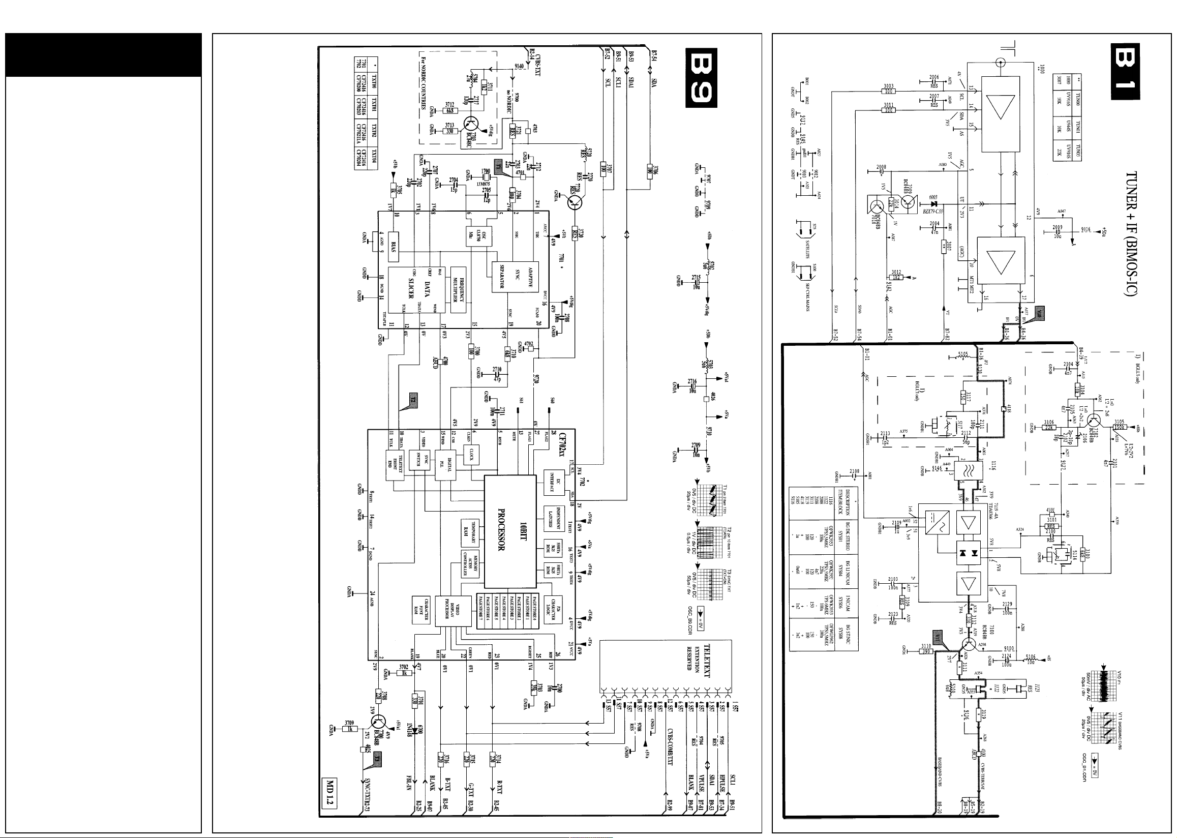
Text
Diagram
Tuner & IF Diagram
Page 3
3PHILIPS MD 1.2E/AA
PCB Identification
Safety instructions for repairs,
Maintenance instructions,
Warnings and Notes
Safety instructions for repairs
1. Safety regulations require that during a repair
the set should be connected to the mains via
an isolating transformer;
safety components, indicated by the symbol
▲ should be replaced by components
identical to the original ones;
when replacing the CRT, safety goggles must
be worn.
2. Safety regulations require that after a repair
the set must be returned in its original
condition. In particular attention should be
paid to the following points:
As a strict precaution, we advise you to
resolder the solder joints through which the
horizontal deflection current is flowing, in
particular:
• all pins of the line output transformer (LOT);
• fly-back capacitor(s);
• S-correction capacitor(s);
• line output transistor;
• pins of the connector with wires to the
deflection coil;
• other components through which the deflection current flows.
- The cabinet should be checked for defects to
avoid touching of any inner parts by the
customer.
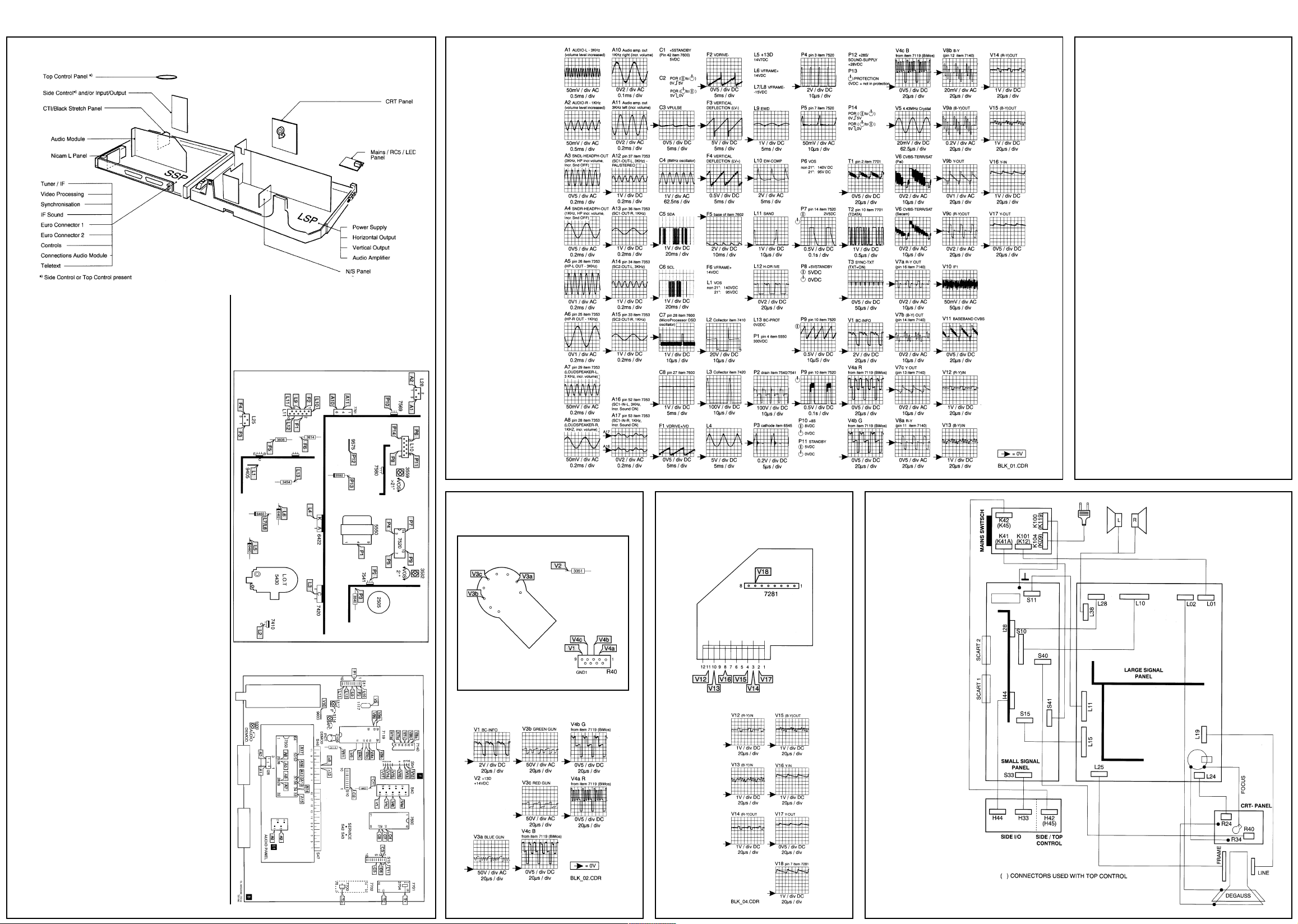
Test Point
Large signal panel
Waveforms
Test Point - CRT Panel
Test Point -
CTI/Black Stretch Panel
Service Modes
DST, Error messages, Protections,
Faultfinding and repair tips
In this chapter the following paragraphs are
included:
6.1 Test points
6.2 Service Modes and Dealer Service Tool
(DST)
6.3 Error codes and “blinking LED” procedure
6.4 Protections
6.5 Fault finding and repair tips
6.1 Test points
The MD1 chassis is equipped with test points in
the service printing. These test points are
referring to the functional blocks:
* A1-A2-A3, etc.:Test points for the audio
processing circuitry
* C1-C2-C3, etc.: Test points for the control
circuitry
* F1-F2-F3, etc.: Test points for the frame drive
and frame output circuitry
* L1-L2-L3, etc.: Test points for the line drive
and line output circuitry
* P1 -P2-P3, etc.: Test points for the power
supply
* T1-T2-T3, etc.: Test point for the teletext
circuitry
* V1-V2-V3, etc.: Test points for the video
processing circuitry
6.2 Service modes and Dealer Service
Tool(DST)
For easy installation and diagnosis the dealer
remote control RC7150 is introduced. The
RC7150 can be used for all new TV sets,
including all set of the MD1 chassis. The
Wiring
Diagram
Note:
This resoldering is advised to prevent bad
connections due to metal fatigue in solder
joints and is therefore only necessary for
television sets older than 2 years.
- The wire trees and EHT cable should be
routed correctly and fixed with the mounted
cable clamps.
- The insulation of the mains lead should be
checked for external damage.
- The mains lead strain relief should be checked
for its function in order to avoid touching the
CRT, hot components or heat sinks.
- The electrical DC resistance between the
mains plug and the secondary side should be
checked (only for sets which have a mains
isolated power supply).
This check can be done as follows:
• unplug the mains cord and connect a wire
between the two pins of the mains plug;
• set the mains switch to the on position (keep
the mains cord unplugged !);
• measure the resistance value between the
pins of the mains plug and the metal shielding
of the tuner or the aerial connection on the
set. The reading should be between 4.5 MO
and 12 MO;
• switch off the TV and remove the wire
between the two pins of the mains plug.
Small signal panel
Page 4
4PHILIPS MD 1.2E/AA
Service Modes Cont’d
RC7150 is also called Dealer Service Tool or
DST. The ordering number of the DST (RC7150)
is 4822 218 21232.
6.2.1Installation features for the dealer
The dealer can use the RC7150 for programming the TV-set with presets, TV-settings, Dish
settings.
10 Different program tables can be programmed
into the DST via a GFL or MD2 TV-set
(downloading from the GFL or MD2 to the DST;
see GFL or MD2 service manuals) or by the
DST-l (DST/PC interface; ordering code 4822
218 21277). For explanation of the installation
features of the DST, the directions for use of the
DST are recommended (For the MD1 chassis,
download code 4 should be used).
6.2.2 Diagnose features for the service
The MD1.2 sets can be put in the two service
modes via the DST RC7150. These are the
Service Alignment Mode (SAM) and the Service
Default Mode (SDM). SDM can also be entered
by short circuiting the “service” pins on the SSP.
6.2.2.1 Service Default Mode (SDM)
Entering the SDM:
- By transmitting the “DEFAULT’ command with
the RC7150 Dealer Service Tool.
- By temporarily shorting pins S42 and S43 on
the Small Signal Panel.
Exiting the SDM:
- Switch the set to stand-by (the error buffer is
also cleared).
Note:
When the mains power is switched off while the
set is in SDM, the set will enter to SDM immediately when the mains is switched on again.
The SDM has the following pre-defined conditions for all microprocessor controlled tuning
and linear functions:
- For recognition of the SDM “SER” is displayed
at the top of the screen.
- Tuning at 475.25 MHz (Secam on Multi
France sets (with Nicam L), PAL on other
sets).
- Volume level is set to 25% (of the maximum
volume level). Other picture and sound
settings are set to 50%.
- Auto switch off disabled (normally the set is
automatically switched off when no video
signal (IDENT) was received for iS minutes).
- Sleep timer is disabled.
- All other controls operate normally.
- When the microprocessor supports the
blinking LED” procedure (See 6.3) and an
error code is present in the error buffer, the
LED will blink the number of times, equal to
the value of the last error code.
This function will also work when there is
no sound or picture.
6.2.2.2 Service Alignment Mode (SAM)
Entering SAM:
- By transmitting the “ALIGN” command with the
RC7150 Dealer Service Tool (this works both
while the set is in normal operation mode or in
the SDM).
- By pressing the “MENU” and “-“ key on the
local keyboard simultaneously when the set is
in SDM.
Exiting SAM:
Switch the set to stand-by.
Note:
When the mains power is switched off while the
set is in SAM, the set will enter SDM immediately when the mains is switched on again.
In the SAM the following information is displayed on the screen:
- Software version (the software version of the
microprocessor in the set is displayed. This
software version identification corresponds
with the software versions in the Software
Survey as published in the Product Survey.
- Error code buffer (see paragraph 6.3).
- Options (see paragraph 8.4).
- Alignment and geometry information (see
paragraph 8.2.1, 8.3.1 and 8.3.2).
Service Modes, DST, Error messages,
(1)Software version
(2)Error buffer
(3)Options
(4)Alignments and geometry
M12XXx-x.x ①
ER0000000≠
③ E2 N AX xx RD xx
UO N VP xx GD xx
LL N 16 N VA xx BD xx
NI N SS xx VL xx HD xx
TT N D1 xx VS xx HW xx
ET N D2 xx VG xx HP xx
HI N D3 xx VA xx HC xx
14 N D4 xx NL xx HT xx
④
Figure 6.1
Screen of the Service Alignment Mode (SAM)
6.3 Error codes and “blinking LED” proce-
dure
The error code buffer contains all errors
detected since the last time the buffer was
erased. The buffer is written from left to right.
- The last error detected (actual) is the error at
the left side
- The error buffer will be reset in the following
cases:
1. exiting the SAM with the “standby” command
on the remote control
2. transmitting the commands “DIAGNOSE 9 9
OK” with the DST
- By leaving the SAM with the mains switch, the
error buffer is not reset.
Examples:
ERROR: 0 0 0 0 0 0: No error code detected
ERROR: 3 0 0 0 0 0: Error code 3 is the last and
ERROR: 5 3 0 0 0 0: Error code 3 first and error
only detected error
code 5 last detected
The contents of the error buffer can also be
made visible through the “blinking LED”
procedure. This is especially useful when there
is no picture. There are two methods:
1. When the SDM is entered, the LED will blink
the number of times, equal to the value of the
last
error code. The LED will stay off briefly
and blink again the number of times, equal to
the value to the
2. With the DST
last
error code
all
error codes in the error
buffer can be made visible. While in SDM,
transmit the command:
“DIAGNOSE x OK”
where x is the position in the error buffer to be
made visible x ranges from 1, (the last
(actual) error) to 7 (the first error)
The LED will operate in the same way as in
point 1, but now for the error code on position x.
Example:
Error code position
12345 67
Error buffer 2410 0 00
• after entering SDM blink (2x) -
pause
- blink
(2x)
• after transmitting
DST
blink (4x)
• after transmitting
OST
blink -
• after transmitting
DST
nothing happens
“DIAGNOSE 2 OK”
-pause
- blink (4x)
“DIAGNOSE 3 OK”
pause
- blink
“DIAGNOSE 4 OK”
with the
with the
with the
Note!
Note that it may take up to 7 seconds before the
set response to a DIAGNOSE command.
Interruption of the blinking sequence may lead
to incorrect results.
Important!
Not all software versions of the MD1.2E chassis
support the blinking LED procedure and the
DIAGNOSE 99 command. Software versions
NOT supporting the blinking LED procedure are
M12BAx-x.x
Error Error Description Blinking Possible
code LED deflective
0 No error detected — —
1 BIMOS 1x IC7119
2 M5P3400/341 0 2x IC7353
3I2C bus error 3x All 12C-related
4 Wrong EEPROM 4x IC7685 (SSP)
5 EEPROM 5x IC7685
6 Tuner error 6x U1000 (SSP)
7 TXT error 7x IC7702 (SSP)
8 Histogram Proc. 8x IC7210
9 16:9 processor 9x IC7440
10 WSSB module 10x IC7540
11 Dolby processor lix IC7600
and
M12COx-3.x.
components
(TDA8366) error (SSP)
error (SSP)
components
defective (SSP)
error (reserved)
error (16x9 module)
error (WSSB module)
error (Audio module)
Table 6.1 Error code list
Protections, Faultfinding and Repair tips
6.4 Protections
6.4.1 In the MD 1 .2E the following protections
are possible:
Protections generated by the power supply:
• Overload protection ➝ Hick up mode
• Underload ➝ Hick up mode
• Over voltage ➝ Hick up mode
• Under voltage ➝ Hick up mode
Deflection:
• Horizontal Protection ➝ Supply to standby
• EW-Protection ➝ Supply to standby
• Vertical Protection ➝ BIMOS standby
mode
Software protection
• BIMOS 1C71 19 defective ➝ (Error code 1)
Set can be switched between standby and
ON, but there is no picture, no OSD, sound is
only noise.
• SDA or SCL shorted ➝ (Error code 3) Set is
switched to standby via standby line, set tries
to restart.
• No +5Db or +85c at pC ➝ Set is switched to
standby via standby line, set tries to restart.
6.4.2 Power supply protections
The power supply will go to a very good audible
hick-up mode in the following situations:
• Overload protection
• Under load
• Over voltage
• Under voltage
In hick-up mode
Pin 1 of IC7520 starts up from the start circuit for
approximately 2 seconds, immediately after that
the protection is activated. This cycle is constantly repeated in hick-up mode. When the set
is in hick-up mode a short squeak is audible
every 2 seconds.
6.4.3 Horizontal-protection
When the beam current becomes too high for a
long period the voltage across C2450 will drop.
D6450 will start conducting and as soon as the
voltage drop across R3456 is 0V7, TS7450 will
conduct, making PROT high. Via the hold
circuitry of the power supply, the set will stay in
the protection mode (standby) and can only be
reset by switching the set off and on via the
mains switch. If the fault is still present, the set
will switch to standby (protection mode) again.
6.4.4 EW-protection (not for 21” sets)
The East/West protection switches the power
supply to standby via the signal line STANDBYSUPPLY PROTECTION. Via the hold-circuitry of
the power supply, the set will stay in the
protection mode (standby) and can only be reset
by switching the set off and on via the mains
switch. If the fault is still present, the set will
switch to standby (protection mode) again.
The East/West protection detects when the
current through the East/West power output
stage with T57480 is too high.
Note:
A current through the East/West stage that is too
high can be caused by a defective part in the
line-deflection circuitry!
The current through the East/West stage is
measured on the LSP via 2 precision resistors
(R3483 and R3484). In case of a line problem,
the east/west-current becomes too high and the
voltage across resistors R3483 and R3484 rises.
When the voltage level exceeds 0.6V, D6480
starts to conduct and STANDBY-SUPPLY
PROTECTION becomes HIGH. When the
voltage across C2480 is very high
(e.g. when a line problem is already present
when the set is switched on with the mains
switch), D6481 and D6482 conduct and EWPROTECTION is activated very fast.
The East/West protection becomes active in the
following cases:
1. Bad contacts of horizontal deflection circuit:
• bad contacts of horizontal deflection coil
• bad contacts of linearity corrector coil L5421
• bad contacts of S-correction capacitor C2427
2. Bad contacts of flyback capacitor C2425.
3. Shorted flyback diode D6421 or D6423.
4. Shorted S-correction capacitor C2427.
5. Bad solder contacts in the line output stage.
When EW-protection has been active, the line
output transistor 7420 may also be defective.
6.4.5 Vertical-protection
The vertical output stage creates VERTICALPROTECTION pulses at every flyback pulse
when it is functioning correctly. These pulses are
sensed by the BIMOS IC7119-4D on pin 37.
When the pulse train is interrupted, the BIMOS
will switch to BIMOS STANDBY mode. In the
BIMOS STANDBY mode, the BIMOS switches
off the VDRIVE+ and VDRIVE- while the RGB
outputs are blanked. Circuit breaker 1463 may
be open. Probably, the line output stage will not
work and the power supply will switch to hick-up
mode (under voltage protection).
6.4.6 Software protection
The software protection is managed by the
microprocessor. It continuously verifies the
presence of the +5 and +8 supply voltages on
pin 34 and the activity of the PC bus. When the
protection becomes active, the software will
switch the power supply on and off continuously
via the STANDBY line. In this situation the
power supply produces a squeaking sound.
Service Modes, DST, Error messages,
- I2C protection
The I2C bus is controlled at each I2C command. Therefore every I2C command has a
defined start/stop condition. When the defined
start/stop condition is repeatedly incorrect,
error 3 is placed in the error buffer and the set
switches to software protection.
I2C protection is generated in the following
situations:
• SDA shorted to earth
• SCL shorted to earth
• SDA and SCL shorted
When SCL or SDA is shorted, the set tries to
restart and the LED lights in a clearly recognisable pattern.
• SDA/SCL shorted when the set is switched
ON with the mains switch:
LED is 8 seconds RED, 8 seconds GREEN,
flashes RED, 8 seconds GREEN, flashes
RED, 8 seconds GREEN, flashes RED,
etcetera.
• SDA/SCL shorted during operation LED is 8
seconds GREEN, flashes RED, 8 seconds
GREEN, flashes RED, et cetera.
- +5Db and +8Sc protection of the microprocessor +5Db and +8Sc are the main supply
voltages of the entire small signal processing
of the set. At pin 34 the microprocessor
senses whether the supply voltages +5SDb or
+8Sc coming from the power supply are
present. When one or both the supply
voltages are missing, the set switches to
software protection.
6.5 Fault finding and repair tips
Note that for 21” sets, voltages and waveforms
may differ.
6.5.1 General
LED indication after start-up procedure is
completed
- No LED
Set is switched OFF, supply problem or
microprocessor problem.
- LED continuously
Set is in standby, control part defective,
standby mode defective.
- LED blinking
Set in SDM, transmitting error buffer.
Audible checks
- Demagnetisation audible: mains voltage is
present at LSP.
- EHT audible: supply is operational (line output
stage only works in case VOS (+140V for 25
& 29”; +95V for 21”) is present.
- Hick-up sound power supply audible: power
supply is shorted. Check the LOT (item 5430)
and the line output transistor T57420.
6.5.2 Fault finding in the power supply
In case of a power supply problem, the power
supply can be simplified to a stand alone power
supply at low voltages (low risk) as follows:
Control part of the power supply
1. Disconnect the SSP (as a result the line will
not function any more and therefore will no
longer be a load of the power supply) or
disconnect the line by removing jumper 9400
and R3400 (if present) on the LSP.
2. Connect an external DC power supply
between supply pin 1 IC7520 (via a diode e.g. BYD33D - with cathode to supply pin 1
IC7520) and hot earth (e.g. earth of the big
smoothing capacitor C2505).
3. Connect a oscilloscope to test point P4 at pin
3 IC7520.
4. Turn up the external DC supply voltage slowly
to 17V DC.
Remark:
The IC starts at a supply voltage of 14V DC,
after that the supply voltage can drop to approx.
9V DC. At approximately 18V DC, over voltage
protection becomes active, resulting in a supply
voltage drop below 7V DC before a new start-up
is performed by turning up the supply voltage
above 14V DC.
5. The correct (measured) situation is displayed
in . Other results indicate a defect in the
power supply control part (IC7520 or peripheral components at pins 10 or 11).
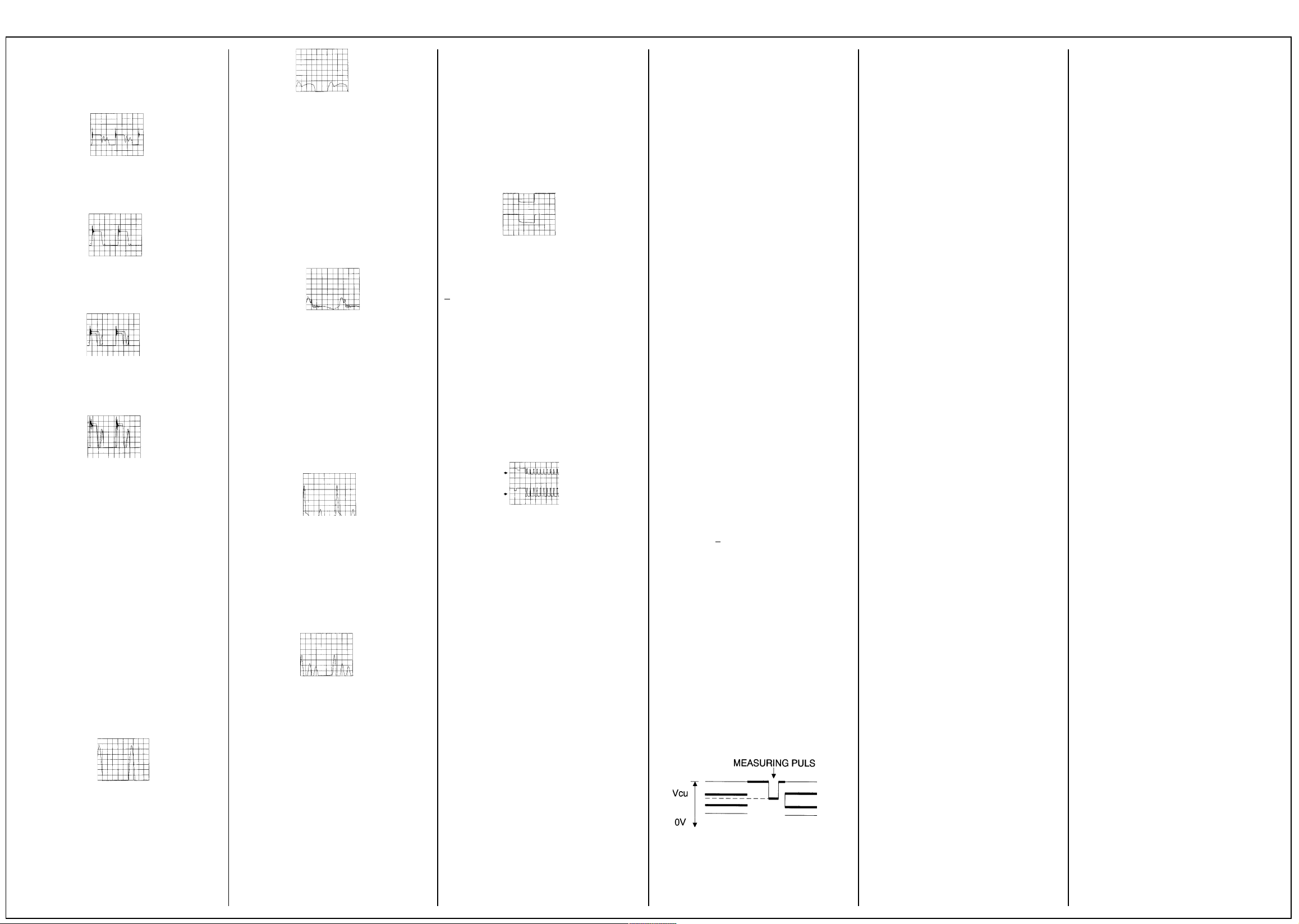
Figure 6.2
5V/div; 5u5/div
➝ 40KHz pulse
Energy transfer of the power supply (only if
control part is OK)
6. Apply action 1, 2 and 4 as described earlier..
7. Connect a lamp of 230V/100W across the
VOS output capacitor C2569.
8. Connect a 1kΩ resistor between the +5
STANDBY (connector 7L10) and the
STANDBY line (connector 8L10) to switch the
power supply to normal operation.
9. Connect the mains connector to a VARIAC
but leave it at 0.
10.Connect a voltmeter across C2569 and an
oscilloscope between the drain of T57541 (25
& 29”) or T57540 (21”) and hot earth.
11.Slowly increase the mains input voltage by
the VARIAC (in this way further damage to the
power supply can be avoided).
Protections, Faultfinding and Repair tips,
The waveforms for the following mains voltage
are given:
Mains in voltage
10V AC: 20kHz and VOS 7V5
20V AC: 40kHz and VOS 30V
40V AC: 40kHz and VOS 80V
65V AC: 40kHz and VOS 140V
> 65V AC: Stable situation, so 40kHz
and 140V
In case of a feedback problem, the situation will
not stabilise or the voltage will exceed 140V
(95V with 21”)
Page 5
5PHILIPS MD 1.2E/AA
Service Mode Cont’d
1. Figure 6.3:
Mains in 10VAC
10V/div; bus/div
2. Figure 6.4:
Mains in 20V AC
20V/div; 5uS/div
➝ 40kHz pulse
➝ VOS 30V
3. Figure 6.5:
Mains in 40V AC
50V/div; 5uS/div
➝ 40kHz pulse
➝ VOS 80V
4. Figure 6.6:
Mains in 65V AC
50V/div; 5uS/div
➝ 40kHz pulse
➝ VOS 140V
6.5.3 Fault finding of the horizontal circuitry
When the horizontal circuitry itself is defective, it
can be simplified to a stand alone “switched
mode supply” at low voltages (low risk) as
follows:
1. Disconnect the set from mains.
2. Disconnect the SSP by removing all cables to
the SSP.
3. Connect an external 50V DC (or 40V DC)
supply with current measurement possibility
across C2400.
4. Replace the HDRIVE by an external LF
generator (1TL level (between 0 and 5V); duty
cycle 50%) with a 16 kHz pulse at the base of
TS741 0 (near LOT at the side of the PCB).
5. Connect a oscilloscope to test point L1
(collector of line output transistor 7420).
Possibilities:
1. Figure 6.7:
L3; test point at collector line output transistor
(7420)
50V/div; 10pS/div
Current from external DC supply approx. 100mA
Observation: normal 16kHz pulses and 100mA
supply current
Correct horizontal circuitry
Note that the amplitude of the signal strongly
depends on the frequency of the generator.
2. Figure 6.8:
L3; test point at collector line output transistor
(7420)
50V/dlv; 10µS/div
Line deflection open:
Current from external DC supply is
approximately 100mA.
Observation: small pulse followed by wide
pulse and 100mA supply current
Causes: horizontal deflection coil open linearity
coil L5421 open S-correction C2427 open
3. Figure 6.9:
L3; test point at collector line output transistor
(7420)
50V/dlv; 10µS/div Current from external DC
supply approx 500mA!!
Observation: fast oscillations and 500mA
supply current
Cause:horizontal deflection shorted (e.g. line
deflection coil shorted)
When the line deflection is not completely
shorted but only a number of windings are
shorted, the waveform does not show the
oscillation and the current of the external DC
supply is approximately 200mA.
4. Figure 6.10:
L3; test point at collector line output transistor
(7420)
100V/div; 10µS/div
Current from external DC supply is
approxImately 150mA
Observation: flyback time is shorter, one extra
pulse in between, 150mA supply current
Cause: flyback capacitor C2425 open
5. Figure 6.11:
L3; test point at collector line output transistor
(7420)
100V/div; 10µS/div
Current from external DC supply > 1A
Observation: 2 pulses per cycle extra and
supply current from more than 1A
Cause: short-circuit in picture tube (e.g. EHT to
Aquadag)
Service Modes, DST, Error messages,
6.5.4 Fault finding “no picture, no protection” (problem in the video controller IC part
TDA8366-4C)
When there is no picture and no protection, it is
most likely that there is a problem with the
BC_INFO caused by the TDA8366, the RGB
amplifiers or the picture tube.
For measuring, connect a video generator (e.g.
PM5518) at the aerial input with a white pattern
to the tuner. Trigger the oscilloscope field
frequent. A stable picture is obtained if triggered
with VDRIVE+ at pin 4 S11.
Normal start up procedure
1.First phase of start up; 4 white measuring
lines (lines 15,16, 17, 18) and the main
picture is muted (wave forms are better visible
if the picture tube is cold);
Figure 6.12:
Red (pin 8 of connector R43 on the CRT panel)
and green gun (pin 6) 100V/div DC;
100 µs/div
The total beam current is measured and fed
back to pin 16 TDA8366 (IC7119)
The TDA8366 checks the voltage at pin 16 of
the TDA8366 during these lines
<4.5V: set remains in this phase
<4.5V: set continues with start up phase 2
2. Second phase of start up; each beam is
separately measured and the main picture is
still muted. Line 15 is Red, line 16 is Green
and line 17 is Blue. BC_INFO is measured.
- differences between the lines (guns) are
compensated
- when the differences are minimal the set
continues with phase 3, otherwise it remains
in phase 2
Figure 6.13:
Red (lower line) (pin 8 of connector R43 on the
CRT panel) and green (upper line) gun (pin 6)
50V/div AC; 100µs/div
3. After start up the picture is present and
differences in cut-off points of the R, the G
and the B gun are compensated continuously.
Repair procedure
Typical situation: no picture and no error
codes
- Switch the set on.
- In a 4:3 set, press “picture size” to switch the
set to “16:9 compressed” mode.
- In a 16:9 set, shift down the picture with the
cursor keys.
The start up phase of the set can be identified:
1. A bright white horizontal line at the top; the
rest of the picture is dark (set hangs in first
phase of start up procedure) Oscilloscope
picture of the voltage over the guns looks like
figure 6.12.
TDA8366 (IC7119), picture tube and RGB
amplifiers are OK
There should be 4.5V at pin 16 TDA8366.
Possible problem: if there is no 4.5V present at
pin 16 of TDA8366, there is a defect (in one or
more of the components) in the BC_INFO
feedback loop.
2. Small horizontal red, green and blue lines at
the top; the rest of the picture is dark (set
hangs in second phase of start up procedure)
TDA8366 is OK
Possible problem: one or more of the guns of
the picture tube are bad.
Measure at pin 16 TDA8366 which feedback
line(s) (the R or G or B line) is/are smaller; the
corresponding amplifier(s) or gun(s) is/are faulty.
3. No lines visible (picture dark)
Measure pin 16 TDA8366; possible measurements:
- 0V: Check TDA8366
(sandcastle and the
supply voltage)
-5V: Check RGB amplifiers
Short pin 16 TDA8366 to
ground, now there will be
measuring lines (at continuously
5V, phase 1 and 2 is bypassed)
- Pulses: there is a measuring line, so the
TDA8366 is OK
Measure on cathode on the CRT
panel if the measuring lines are
present:
Yes ➝ BC_INFO circuit is open
or no HEATER voltage
No ➝ RGB amplifier problem
8. Electrical alignments
General: the Service Default Mode (SDM) and
Service Alignment Mode (SAM) are
described in chapter 6.
Alignment conditions:
All electrical adjustments should be performed
under the following conditions:
• Power supply voltage: 240V±10%, 50Hz ±5%.
• Warm-up time: ≈ 10 minutes
• The voltages and oscillograms are measured
in relation to the tuner earth.
• Test probe: Ri > 10MΩ; Ci < 2,5 pF.
8.1 Adjustments on the large signal panel
8.1.1 95V/140V supply voltage
For 21” TV-sets
Connect a voltmeter to the cathode of D6567.
With the aid of R3532 adjust the power supply
voltage to 95V + 0,5V
For sets 21”
Connect a voltmeter to the cathode of D6567.
With the aid of R3559 adjust the power supply
voltage to 140V± lV.
8.1.2 VG2 adjustment
Connect a pattern generator displaying a full
black picture. Switch the TV-set to the service
default mode (see chapter 6). Connect an
oscilloscope to the picture tube cathodes for
red, green and blue (pins 6, 8 en 11 of the
picture tube socket). Set the oscilloscope to DC,
50 V/div and 2 ms/div. Measure the DC level of
the measuring pulses at the end of the
frameblanking (see fig. 8.1). Using the Vg2
potentiometer on the linetransformer (bottom
potentiometer) the measuringpulse with the
highest level must be set to +160V ± 2V.
8.1.3 Focusing
Is aligned using the focuspotentiometer on the
linetransformer (top potentiometer).
8.2 Alignments on the small signal panel
8.2.140.4 MHz IF filter (only for sets with
SECAM LL’ reception)
Using a signal generator (e.g. PM5326) and a
capacitor of 5,6 pF supply a 40,4 MHz signal to
pin 17 of the tuner. Connect an oscilloscope to
pin 1 of filter 1016. Switch on the set and select
in the installation menu MANUAL; SYSTEM
EUR.W. Align coil L5117 for maximum DC
output voltage.
8.2.2 AFC
Switch the set to service default mode (see
chapter 8).
Using a pattern generator (e.g. PM5518) supply
a signal on a frequency of 475,25 MHz
Align coil L5114 for optimal picture quality.
8.2.3 Picture demodulator (only for sets with
SECAM LL’ reception)
Using a signal generator (e.g. PM5326) supply a
32.95MHz signal via a 5,6 pF capacitor to pin 17
of the tuner. Align the signal level of the
generator so that the DC-voltage on pin 5 of the
tuner is 5V.
Switch on the set and select in the installation
menu MANUAL; SYSTEM FRANCE. Align
capacitor C2106 for minimal voltage on pin 5 of
the tuner.
8.2.4 RF-AGC
If the signal of a strong local transmitter is
distorted, align the value for AX (AGC crossover) in the service menu (see chapter 8) until the
picture is no longer distorted.
8.2.5 Audio demodulator (Not for sets with
LL’ and NICAM reception possibility)
Using a signal generator (e.g. PM5326) supply a
38.9MHz signal via a 5,6 pF capacitor to pin 17
of the tuner.
Connect an oscilloscope (2ms/div) to pin 12 of
IC7033 (TDA3845). Align coil L5030 for minimal
amplitude.
8.3 Picture tube alignments
8.3.1 White balance
Connect a pattern generator and select a white
picture. Set contrast to maximum (63) for 21” or
to 40 for 21” tv-sets. Use the / keys to
select an alignment and the / keys to
change the value. Set GD to 50, RD to 57 and
BD to 45.
If necessary change the settings for RD and BD
for a correct white balance.
8.3.2 Geometry adjustments (for software
versions M12COx-3.x and M12BAx-x.x)
Connect a pattern generator and select a
geometry pattern (signal at 475.25 MHz)
• Switch to the Service Default Mode, then to
the Service Alignment Mode.
• Select the desired alignment with the /
keys.
• Change the selected alignment with the /
keys.
• A value between 0 and 63 can be selected.
• Changed values are stored immediately.
Vertical
VP: Vertical Shift
Set this for the correct vertical position.
VA: Picture height
Set this for the correct picture height.
VL: Vertical linearity
Set this so that the vertical centre of the
➝
➝
➝
➝
➝
➝
➝
picture is at the centre of the tube.
VS: Vertical S-correction
Set this so that the height of the squares in the
top of the picture equal the height in the bottom
of the picture.
Horizontal
HD: Horizontal shift.
Set this so that the horizontal centre of
the picture is on the centre of the tube.
For sets with a screen size larger than 21”, the
following alignments can be done as well. For
21” sets these alignments have no function.
HW: East-west width
Align the picture width with this.
HP: East-west parabola correction
Set this so that the vertical lines at the
sides of the screen are straight.
HC: East-west corner-correction.
Set this so that the vertical lines are
straight in the corners.
HT: Trapezium correction
Set this so that the vertical lines are as
vertical as possible.
Adjustments for 16:9 sets (reserved)
16 = N 4:3 tube (options SS, D1, D2, D3 and
D4 not available (blue))
16 = Y 16:9 tube (options SS, D1, D2, D3 and
D4 available)
8.4 Options
E2: Number of Euro/Scart connectors
(options N or Y)
N 1 Euro/Scart connector present
Y 2 Euro/Scart connectors present
UO: Tuner type
N UHFNHF tuner (item 1000 is UV9165)
Y UHF tuner (item 1000 is UV9445).
Used in the United Kingdom (/05 sets)
LL:Nicam L (options N or Y)
N Nicam L not present
Y Nicam L present (Nicam L panel
required and item 7353 is M5P3410)
NI:Nicam (stereo) sound (options N or Y)
N Only 2C5 stereo, no Nicam (item 7353 is
M5P3400)
Y 2C5 and Nicam stereo (item 7353 is
M5P3410)
U: Teletext (options N or Y)
N No Teletext present
Y Teletext present
ET: (Eastern Europe) teletext type
(options N or Y)
N No Eastern Europe teletext
Y Eastern Europe teletext (/58 sets)
14: 14:9 Picture format supported by 4:3
tube (options N or Y)
N Not supported
Y Supported
HI: Histogram (not with software version M1
2BAx-x.x)
N No Histogram present (options VG, VA
➝
and NL not available (blue))
Y Histogram present (options VG, VA and
NL available)
M2: MD1 .1 E or MD1 .2E chassis
(only with software version M12BAx-x.x)
N MD1.1E chassis
Y MD1.2E chassis
Page 6
6PHILIPS MD 1.2E/AA
Alignments
(16;9 & Surround Sound)
8. See MD1.2E AA for a description of the basic
alignments for the MD1 .2E AA software.
Software version:
M12BAx-4.x
M1200x-3.2
4:3 sets (NO flashing LED procedure, replaced
by M12COx-4.0)
M12COx-4.0
4:3 sets (WITH flashing LED procedure,
replaces M1200x-3.2)
In the Service Default and Service Alignment
Mode widescreen sets switch to Wide Screen
format. All the geometry alignments also have to
made in the WideScreen mode.
In this supplement the additional options for
16:9 and Dolby Pro Logic sets with the following
software are described:
M12COx-5.1
(or later) 16:9 sets
(also suitable for 4:3 sets)
Ml 2DOx-1.0
(or later) Dolby Pro Logic sets
(4:3 and 16:9)
SS Picture dimension and rotation coil
dependent setting.
SS Picture tube / rotation coil
1 32” with rotation coil
2 28’ with rotation coil
3 24” with rotation coil
4 32” without rotation coil
5 28” without rotation coil
6 24” without rotation coil
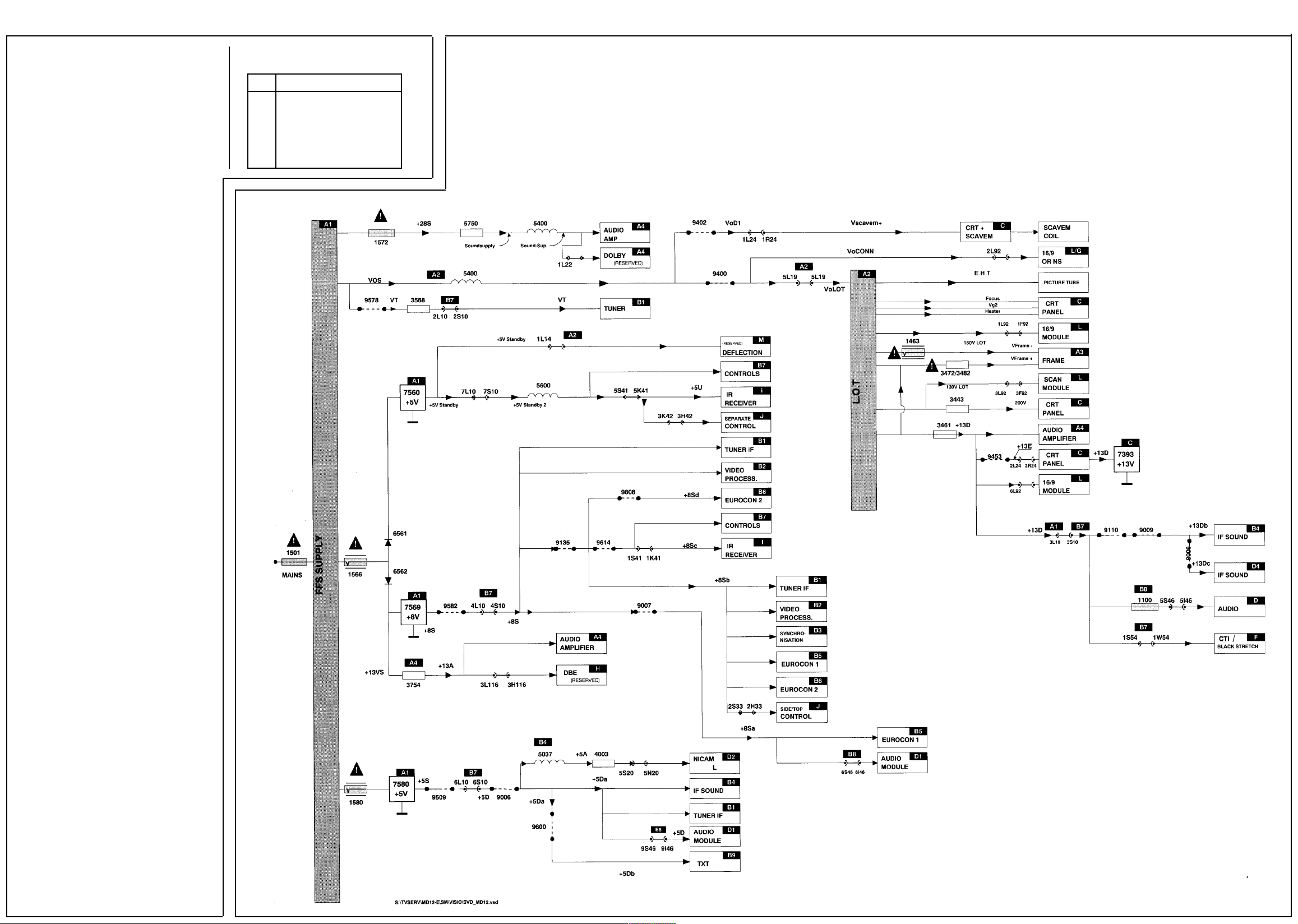
Supply Voltage Diagram
8.1 Options and alignments
HI Histogram option. This option is not
used and is not selectable.
WB Format detection for 4:3,14:9 or 16:9
picture (16:9 sets only) and Dolby Pro
Logic sound (Dolby Pro Logic sets
only) by the teletext IC.
Y Automatic detection on
N Automatic detection off
Automatic 16:9 detection via the Scart
cable also functions if ‘WB N’ is set.
16 Picture tube aspect ratio
Y 16:9 picture tube
N 4:3 picture tube
If ‘16 N’ is set, parameters WB*, RT,
SS, Dl, D2, D3 and D4 automatically
become blue and are made
non-selectable.
* In Dolby Pro Logic sets the WB option can be
selected independently of the 16 option, as
the automatic sound detection can also be
switched on and off in this manner.
RT Rotation coil (picture tilt)
Y Rotation coil present; An option to tilt the
picture appears under the YELLOW key in
the operating menu.
N No rotation coil present.
D1 HD-value deviation in 4:3, Zoom 14:9
and Zoom 16:9 in relation to
WideScreen mode.
D2 HD-value deviation in SuperWide
(panorama) format in relation to
WideScreen mode.
D3 HP-value deviation in 4:3, Zoom 14:9
and Zoom 16:9 in relation to
WideScreen mode.
D4 HP-value deviation in SuperWide
(panorama) format in relation to
WideScreen mode.
The alignment settings are dependent on picture
tube format:
Picture tube format 20” 24” 28” 32”
D1 12 9 9 8
D2 2 3 3 5
D3 10 9 9 8
D4 7 9 9 8
Page 7

7PHILIPS MD 1.2E/AA
Controls Diagram
Page 8

8PHILIPS MD 1.2E/AA
Audio Module Diagram
Page 9

Audio Output Diagram
9PHILIPS MD 1.2E/AA
Audio Module Connections Diagram
Page 10

10PHILIPS MD 1.2E/AA
16:9 PCB Diagram
Page 11

11PHILIPS MD 1.2E/AA
Click Fit Diagram
DBE PCB Diagram
CTI/Black Stretch Diagram
Page 12

12PHILIPS MD 1.2E/AA
CRT Base PCB Diagram
(16:9 & Surround Sound)
Page 13

13PHILIPS MD 1.2E/AA
CRT PCB Diagram
Page 14

Control & Input/Output Diagram
14PHILIPS MD 1.2E/AA
Horizontal Output Diagram
N/S Panel Diagram
Page 15

15PHILIPS MD 1.2E/AA
Dolby Module Diagram
Page 16

16PHILIPS MD 1.2E/AA
Mains/RC5/LED PCB Diagram
Mains /RC5/LED PCB Diagram
(Classic Line)
Mains & Front Control PCB Diagram
Nicam L Module
Diagram
Sync Diagram
Page 17

17PHILIPS MD 1.2E/AA
Power Supply Diagram (21” only)
Page 18

18PHILIPS MD 1.2E/AA
Power Supply Diagram (Over 21”)
Page 19

19PHILIPS MD 1.2E/AA
Scart
Diagram 1
Sound IF Diagram
Scart Diagram 2
Surround Sound PCB Diagram
Page 20

20PHILIPS MD 1.2E/AA
Wiring Diagram
(16:9 & Surround Sound)
Vertical
Output
Diagram
Video
Processing
Diagram
 Loading...