

Philips MCR220BK Service Manual
CD Clock Radio
AJ3970
MCR220BK
all versions
Handling Chip Components and Safety ..........................1 - 1
Technical Specification & Service tools...........................2 - 1
Service Measurement......................................................2 - 2
Instructions for use.................................................3 - 1..3 - 2
Disassembly Diagram......................................................4 - 1
CD Service Test program................................................4 - 2
Block Diagram .................................................................5 - 1
Wiring Diagram................................................................6 - 1
Main Board - Circuit Diagram
AF part.....................................................................7 - 1
Control part..............................................................7 - 2
Tuner part................................................................7 - 3
Main Board - Layout Diagram
Layout diagram (component side)...........................8 - 1
Layout diagram (copper side)..................................8 - 2
IC D01 - AX CD Board
Circuit Diagram........................................................9 - 1
Layout Diagram ......................................................9 - 2
Alarm Board
Circuit Diagram......................................................10 - 1
Layout Diagram ....................................................10 - 1
Play Select Board & CD Door Switch Board
Circuit Diagram......................................................11 - 1
Layout Diagram ....................................................11 - 1
Exploded view - cabinet.................................................12 - 1
Mechanical partslist.......................................................12 - 2
Electrical partslist .............................................13 - 1 .. 13 - 6
© 3140 785 22940
Published by LX 0222 Service Audio Printed in The Netherlands Subject to modification
TABLE OF CONTENTS
©
Copyright 2001 Philips Consumer Electronics B.V. Eindhoven, The Netherlands
All rights reserved. No part of this publication may be reproduced, stored in a retrieval
system or transmitted, in any form or by any means, electronic, mechanical, photocopying,
or otherwise without the prior permission of Philips.
CLASS 1
LASER PRODUCT
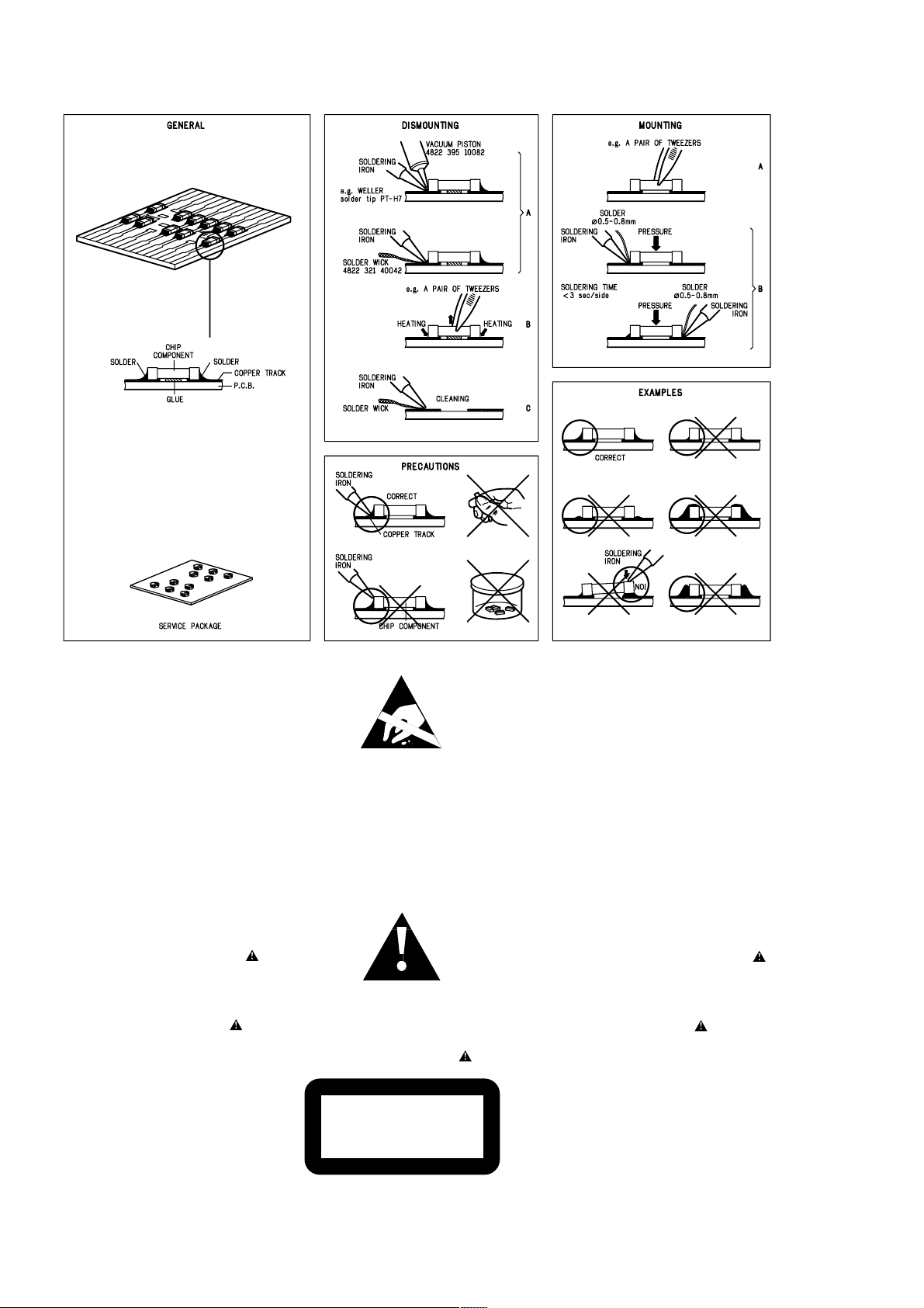
HANDLING CHIP COMPONENTS
1 - 1
© WARNING
All ICs and many other semiconductors are susceptible to
electrostatic discharges (ESD). Careless handling during
repair can reduce life drastically.
When repairing, make sure that you are connected with the
same potential as the mass of the set via a wristband with
resistance. Keep components and tools at this potential.
f ATTENTION
Tous les IC et beaucoup d´autres semi-conducteurs sont
sensibles aux décharges statiques (ESD). Leur longévite
pourrait être considérablement écourtée par le fait qu´aucune
précaution nést prise à leur manipulation.
Lors de réparations, s´assurer de bien être relié au même
potentiel que la masse de l´appareil et enfileer le bracelet
serti d´une résistance de sécurité.
Veiller à ce que les composants ainsi que les outils que l´on
utilise soient également à ce potentiel.
©
Safety regulations require that the set be restored to its
original condition and that parts which are identical with
those specified be used.
Safety components are marked by the symbol
f
Les normes de sécurité exigent que l`appareil soit remis
à l`état d`origine et que soient utilisées les pièces de
rechange identiques à celles spécifiées.
Les composants de sécurité sont marqués
d WARNUNG
Alle ICs und viele andere Halbleiter sind empfindlich
gegenüber elektrostatischen Entladungen (ESD).
Unsorgfältige Behandlung im Reparaturfall kann die
Lebensdauer drastisch reduzieren.
Sorgen Sie dafür, daß Sie im Reparaturfall über ein Pulsarmband mit Widerstand mit dem Massepotential des
Gerätes verbunden sind.
Halten Sie Bauteile und Hilfsmittel ebenfalls auf diesem
Potential.
d
Bei jeder Reparatur sind die geltenden Sicherheitsvorschriften zu beachten. Der Originalzustand des Gerätes
darf nicht verändert werden. Für Reparaturen sind Originalersatzteile zu verwenden.
Sicherheitsbauteile sind durch das Symbol markiert.
ESD
SAFETY
ñ WAARSCHUWING
Alle IC´s en vele andere halfgeleiders zijn gevoelig voor
electrostatische ontladingen (ESD).
Onzorgvuldig behandelen tijdens reparatie kan de levensduur
drastisch doen vermindern. Zorg ervoor dat u tijdens reparatie
via een polsband met weerstand verbonden bent met hetzelfde
potentiaal als de massa van het apparaat.
Houd componenten en hulpmiddelen ook op ditzelfde potentiaal.
i AVVERTIMENTO
Tutti IC e parecchi semi-conduttori sono sensibili alle scariche
statiche (ESD).
La loro longevità potrebbe essere fortemente ridatta in caso di
non osservazione della più grande cauzione alla loro
manipolazione. Durante le riparationi occorre quindi essere
collegato allo stesso potenziale che quello della massa
delápparecchio tramite un braccialetto a resistenza.
Assicurarsi che i componenti e anche gli utensili con quali si
lavora siano anche a questo potenziale.
ñ
Veiligheidsbepalingen vereisen, dat het apparaat in zijn
oorspronkeliijke toestand wordt teruggebracht en dat
onderdelen, identiek aan de gespecificeerde, worden toegepast.
De Veiligheidsonderdelen zijn aangeduid met het symbool
i
Le norme di sicurezza estigono che l´apparecchio venga
rimesso nelle condizioni originali e che siano utilizzati i
pezzi di ricambiago identici a quelli specificati.
Componenty di sicurezza sono marcati con
©
DANGER: Invisible laser radiation when open.
AVOID DIRECT EXPOSURE TO BEAM.
s Varning !
Osynlig laserstrålning när apparaten är öppnad och
spärren är urkopplad. Betrakta ej strålen.
∂ Advarsel !
Usynlig laserstråling ved åbning når sikkerhedsafbrydere
er ude af funktion. Undgå udsaettelse for stråling.
CLASS 1
LASER PRODUCT
ß Varoitus !
Avatussa laitteessa ja suojalukituksen ohitettaessa olet alttiina
näkymättömälle laserisäteilylle. Älä katso säteeseen !
©
After servicing and before returning the set to customer
perform a leakage current measurement test from all
exposed metal parts to earth ground, to assure no
shock hazard exists.
The leakage current must not exceed 0.5mA.
f
"Pour votre sécurite, ces documents doivent être utilisés par
des spécialistes agréés, seuls habilités à réparer votre
appareil en panne".

2 - 1
TECHNICAL SPECIFICATION
GENERAL
Mains voltage -/00 : 230 V
-/05 : 240V
-/17 : 120 V
Mains frequency -/00/05 : 50 Hz
-/17 : 60 Hz
Power consumption Max. : < 15 W
Standby : < 5 W
Dimension (W x H x D) : 326.5 x 75 x 190 mm
Weight : 1.3 Kg
AMPLIFIER
Output power : 2 x 0.8 W
Speaker impedance : 2 x 8 ohm
Frequency response : 100 Hz - 10 kHz (±3dB)
COMPACT DISC
Frequency response : 100 Hz - 10 kHz ± 2dB
S/N ratio : 60 dB
Channel difference 1 kHz : 2 dB
Channel crosstalk 1 kHz : 40 dB
Laser wavelength : 780 ± 20 nm
Laser light power : < 0.5mW
TUNER - FM SECTION
Tuning range : 87.5 - 108 MHz
IF frequency : 10.7 MHz ± 0.2 MHz
Sensitivity : 22 dBf at 26dB S/N
Selectivity : 20 dB at 300kHz
IF rejection : 50 dB
Image rejection : 20 dB
Crosstalk : 20 dB
TUNER - AM SECTION
Tuning range MW : 525 - 1602 kHz
-/17 : 530 - 1710 kHz
IF frequency : 468 kHz ± 1 kHz
Sensitivity MW : 4000 µV/m at 26dB S/N
Selectivity MW : 16 dB
IF rejection MW : 24 dB
Image rejection MW : 28 dB
SERVICE TOOLS
Audio signal disc SBC 429.......................................................................4822 397 30184
Playability test disc SBC 444
Test disc 5 (disc without errors ) +
Test disc 5A (disc with dropout errors, black spots and fingerprints)
SBC 426/426A.....................................................................4822 397 30096
Burn in test disc (65 min. 1kHz signal at -30 dB level without “pause”)
...................................................................4822 397 30245
.....4822 397 30155
AVAILABLE ESD PROTECTION EQUIPMENT
anti-static table mat
anti-static wristband
connection box (3 press stud connections, 1MΩ) 4822 320 11307
extendible cable (2m, 2MΩ, to connect wristband to connection box) 4822 320 11305
connecting cable (3m, 2MΩ, to connect table mat to connection box) 4822 320 11306
earth cable (1MΩ, to connect any product to mat or to connection box) 4822 320 11308
KIT ESD3 (combining all 6 prior products - small table mat) 4822 310 10671
wristband tester 4822 344 13999
large 1200x650x1.25mm 4822 466 10953
small 600x650x1.25m 4822 466 10958
4822 395 10223
2 - 2
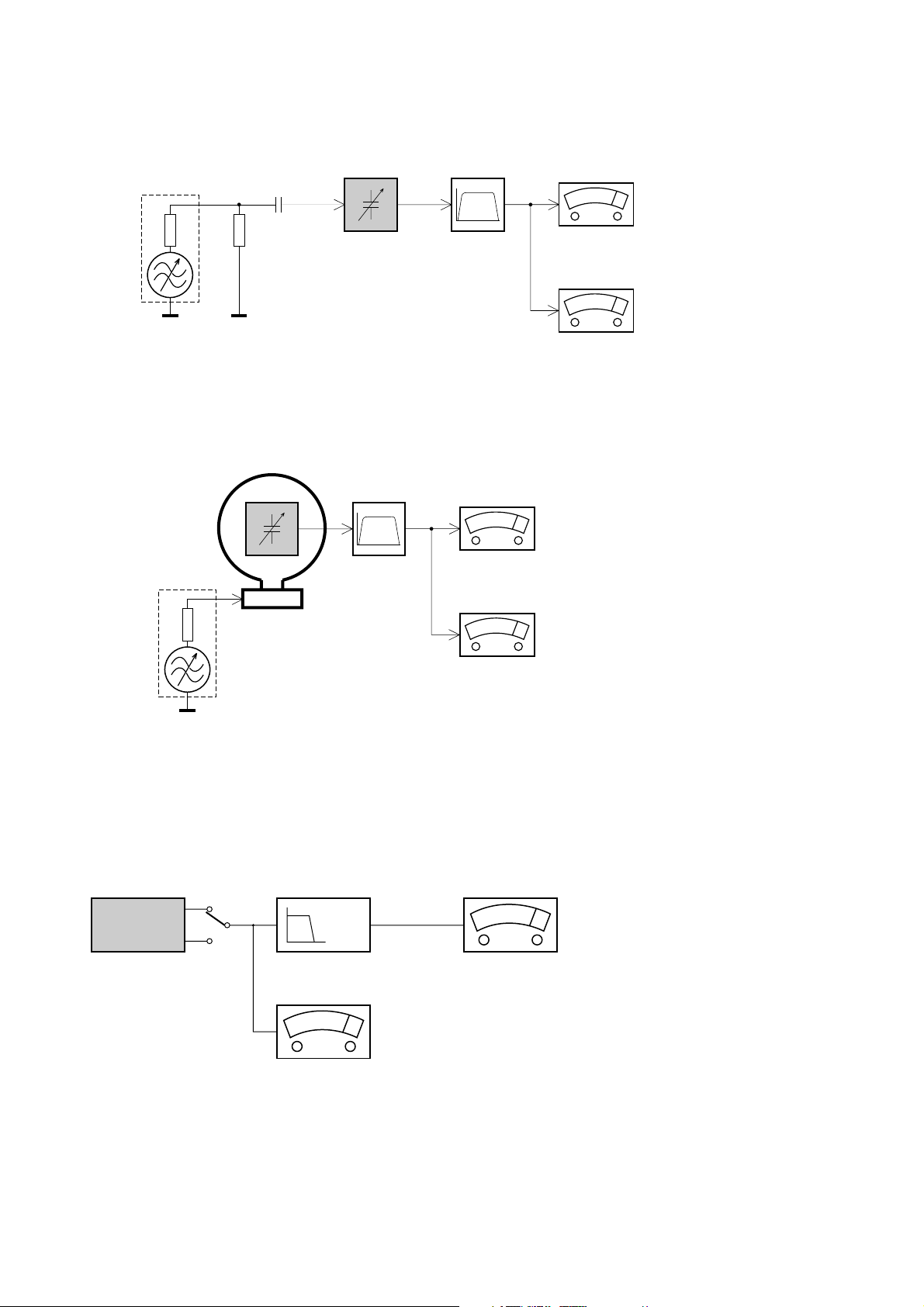
SERVICE MEASUREMENT
Tuner SW
RF Generator
e.g. PM5326
Aerial replacement
DUT
Capacitor
Ri=50Ω
R=50Ω
Bandpass
250Hz-15kHz
e.g. 7122 707 48001
LF Voltmeter
e.g. PM2534
S/N and distortion meter
e.g. Sound Technology ST1700B
To avoid atmospheric interference all AM-measurements have to be carried out in a Faraday«s cage.
Use a bandpass filter (or at least a high pass filter with 250Hz) to eliminate hum (50Hz, 100Hz).
Tuner AM (MW,LW)
RF Generator
e.g. PM5326
Ri=50Ω
DUT
Frame aerial
e.g. 7122 707 89001
Bandpass
250Hz-15kHz
e.g. 7122 707 48001
LF Voltmeter
e.g. PM2534
S/N and distortion meter
e.g. Sound Technology ST1700B
To avoid atmospheric interference all AM-measurements have to be carried out in a Faraday«s cage.
CD
Use Audio Signal Disc SBC429 4822 397 30184 (replaces test disc 3)
L.P.F. = 13
th
order filter 4822 395 30204
DUT
L
R
Low pass filter 22kHz
LEVEL METER
e.g. Sennheiser UPM550
with FF-filter
S/N and distortion meter
e.g. Sound Technology ST1700B
3 - 1
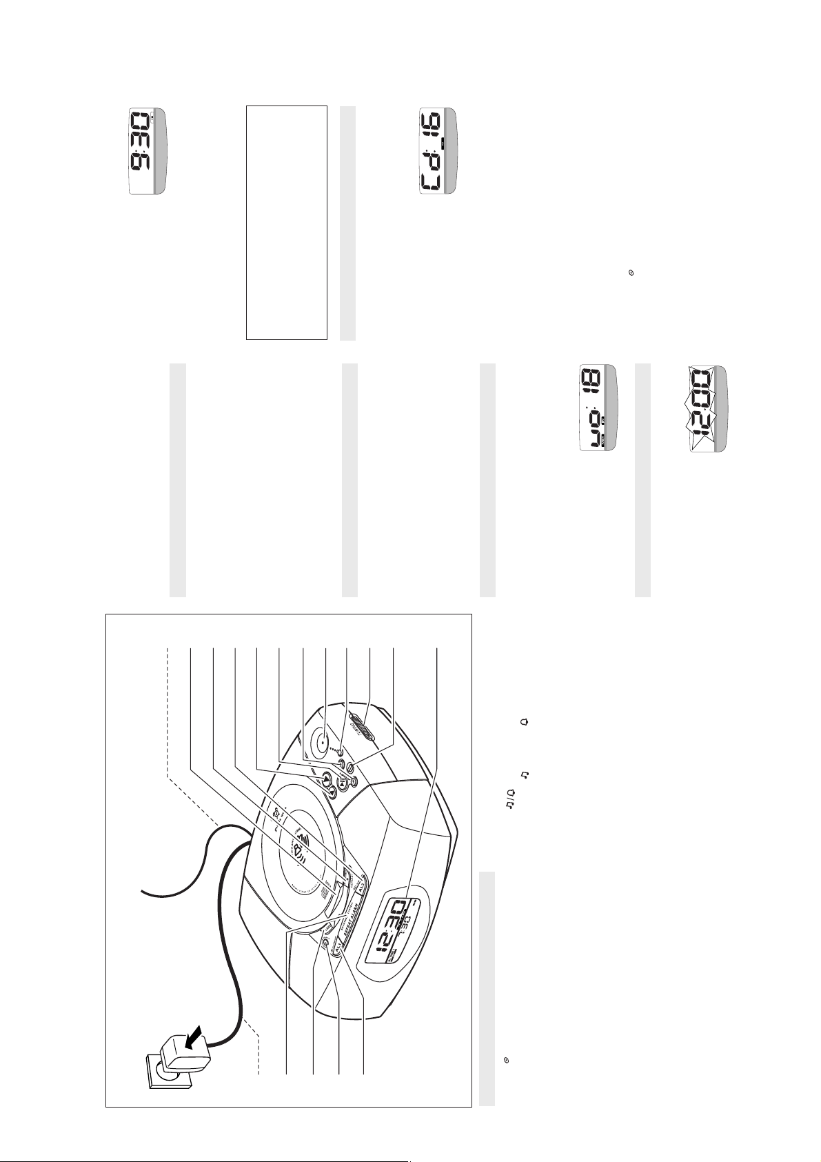
INSTRUCTIONS FOR USE
∞ / §
when you have reached the desired
∞ / §
slowly, minute by minute,
press and release
repeatedly.
Release
setting.
y If you need to adjust the time
3.
.
confirmed when the display stops flashing.
Repeat steps 1-3 for each of the clock or alarm (AL1,
AL2) settings
y After several seconds, the time setting is
Alarm time display
4.
If you have set both alarms, the standby alarm time display
will show the earlier of the two alarm times as priority.
time 5:45.
Insert a CD with the printed side facing up, and close the
door.2.Press PLAY/ PAUSE
E.g. if AL1 = 6:00 and AL2 = 5:45, then the standby alarm
display will show the AL2
CD PLAYBACK
1.
to start playback.
2;
ber of tracks, then your cur-
rent track number, before
'Cd: --' and the total num-
y Display shows:
.
3
or
4
ed incorrectly.
finalized
returning to clock time.
Other possible CD indications before
returning to clock time:
y door is shown if the CD door is not closed.
y noCd is shown if no CD has been inserted / insert-
set.
y nFCd is shown if the CD-R(W) is non-
Adjust the sound with
y Err indicates a general error in operation of the
3.
2;
again to resume playback.
2;
To interrupt, press
Press
Press ALARM RESET to stop playback.
y CD icon flashes.
4.
5.
6.
Note: If CD playback is paused for more than 15
minutes and no controls are pressed, the set
automatically goes to standby mode.
TIME/ ALARM
- toggle to set the times for the clock time, or alarm 1 or 2.
- shows the clock / alarm times and status of the unit.
^
& Display
Check if the power voltage, shown on the AC-DC adapter
plug, corresponds to your local power
supply. If it does not, consult your dealer or service cen-
ter.2.Connect the AC-DC adapter plug to the wall outlet.
To disconnect the set completely from the power supply,
POWER SUPPLY
6
1.
7
90!@#$%
8
withdraw the AC-DC adapter plug from the wall outlet.
3.
bottom of the set.
The serial and production number are located on the
MEMORY BACKUP
Standby power consumption (clock mode)..........2W
low
➟
bright
to adjust the
➟
3
or
low
Toggle REPEAT ALARM/ BRIGHTNESS CONTROL.
If power supply returns after 3 minutes you will need to re-
enter the clock and alarm time settings.
The memory backup conveniently allows your clock and alarm
time settings to be stored for up to 3 minutes when there is a
power interruption e.g. AC power failure.
The complete CD clock radio and lighted display will be
switched off. As soon as the power supply returns, the display
will indicate the correct time.
^
&
BASIC FEATURES
•
- switches off radio / CD timer (SLEEP);
y The brightness of the display toggles between:
1.
Display brightness
- stops the active buzzer, radio or CD alarms for 24 hours.
- selects radio / buzzer alarm mode;
9 AL 2 ( ALARM/ OFF)
4
Volume
Press
- to cancel or switch off radio / buzzer alarm.
- adjusts the sound level.
0 VOLUME 3 , 4
! PLAY / PAUSE 2;
volume level. The volume
- starts / pauses CD playback.
SETTING THE CLOCK AND ALARM TIMES
level uo: is indicated as a number
from 0-32.
- adjusts clock / alarm times
- skips CD tracks / searches for a particular passage.
@ DOWN, UP ∞ , §
Press and hold down TIME/
1.
The time is displayed using the 12 hour clock (PM indica-
tor lights up = PM, off = AM).
waveband.
- shows the radio frequency of your selected
# Tuning indicator
ALARM until the clock or alarm
time display flashes, then
release TIME/ ALARM.
time or alarm displays
• Press TIME/ ALARM repeatedly to toggle between the
- switches on the radio;
- selects the radio waveband.
$ RADIO ON (FM/ AM)
- tunes to a radio station.
% TUNING
to fast adjust both the
∞ / §
hours and minutes settings.
Press and hold down
2.
5
4
3
2
1
1
CONTROLS (see figure 1)
1 AL 1 ( ALARM/ OFF)
selects CD alarm;
to cancel or switch off CD alarm.
to program to your favorite CD track for wake-up track
-
-
alarm option.
-
2 WAKE-UP TRACK
3 SLEEP
- adjusts timer options for CD / radio;
- switch on radio for timer mode.
-changes the brightness of the display window;
-switches off the alarm for a 9 minute period;
-switches off radio / CD timer (SLEEP).
-connect AC-DC adapter plug to wall outlet.
-antenna to improve FM reception.
- lift here to open / close CD door
4 REPEAT ALARM/ BRIGHTNESS CONTROL
5 Power cord
6 Coil antenna
7 CD door
- stops CD / radio playback;
8 ALARM RESET (CD/ RADIO OFF)
3 - 2
NSTRUCTIONS FOR USE
(CD) or RADIO ON (radio) to switch on the
2;
Press
desired mode.
SLEEP
About Sleep
The CD clock radio has a built-in sleep timer which enables
the set to be automatically switched off
during radio or CD playback after a set period of time. There
are 3 sleep times: 60, 30 and 15 minutes.
The sleep function does not change the operation of your
alarm settings.
Setting SLEEP
SWITCHING OFF THE ALARM
There are three ways to switch off the alarm. Unless you
cancel the alarm completely, the 24 HOUR ALARM
RESET will be automatically selected after 59 minutes,
from the time your alarm time first goes off.
24 HOUR ALARM RESET
If you want the alarm mode to be stopped
immediately but also wish to retain the same alarm setting
for the following day:
mode.
1.
• You can also press SLEEP if you want the timer in radio
alarm is reset.
y You will hear a beep tone to confirm the 24 hour
• Press ALARM RESET.
REPEAT ALARM
Select your timer option by pressing SLEEP once or
more until the desired option is
shown.
2.
• Display shows SL: and the timer
NESS CONTROL.
This will repeat your alarm call at 9-minute intervals.
• During the alarm call, press REPEAT ALARM/ BRIGHT-
To cancel the timer function you can either:
options:
60➟ 30➟ 15 minutes ➟ 60➟ 30...
3.
• Press ALARM RESET.
or
,
Note:
• The selected alarm mode
• Repeat if desired up to an hour.
longer shown.
• Press SLEEP once or more until the sleep function is no
• Press REPEAT ALARM/ BRIGHTNESS CONTROL.
indicators flashes throughout the repeat alarm duration.
resumes at the point where the repeat alarm
interrupted.
• If you are using the CD alarm mode, CD playback
• During the CD alarm, CD playback continues for up to an
hour unless you cancel / reset the alarm.
been cancelled.
indicator disappears from the display.
CANCELING THE ALARM COMPLETELY
To cancel the set alarm time before it goes off, or
y You will hear a beep tone to confirm the alarm has
during the alarm call:
• Press AL1 or AL 2 once or more until the selected alarm
, the
3
or
4
operly to a station.
Radio Alarm:
Read the following section if you want to select the
If you have selected the radio alarm, make sure you
have tuned pr
to skip tracks.
∞ or §
Selecting a different track during playback
Press § once or more to skip to the next track(s).
The track number appears briefly in the display when you
press
•
WAKE-UP TRACK alarm option.
2.
Selecting CD WAKE-UP Alarm Mode
You can program and select a CD track number between 1-
99, when the set is in the standby or radio playback mode.
However, if the track number programmed does not exist on
your CD, the CD will start playback from the first track dur-
ing the alarm call.
§
or
∞
when you recognize the passage you
§
more than once to skip to previous tracks.
once and playback will return to the beginning
∞
∞
of the current track.
• Press
During playback, press and hold down
• Press
Finding a passage within a track
1.
or
∞
volume; the display will show 'Cd:' and your
current track number.
Release
y The CD is played at high speed and low
want.
2.
until the desired track number is shown.
§
or
∞
If you want to review your programmed track number,
Set the alarm time for AL1.2.Insert a CD into the CD compartment.
Press AL 1 to select CD alarm mode.
Press WAKE-UP TRACK to activate favorite track pro-
gramming.
Press
1.
3.
y Normal CD playback and standby clock time resumes.
RADIO
Press WAKE-UP TRACK to confirm the selected track
4.
5.
6.
Press RADIO ON (FM/ AM) to switch on the radio.
Press RADIO ON (FM/ AM) again if you wish to
change waveband.
y Display shows 'tu' before returning to clock time.
1.
2.
press WAKE-UP TRACK
number.
y The display returns to standby clock time.
7.
3
or
4
Adjust the sound using
Adjust the TUNING wheel to tune to a radio
station.
3.
4.
To improve reception:
alarm if you have:
Note:
• The buzzer alarm option will automatically replace the CD
ing the position of your set.
optimum reception.
FM: Extend coil antenna at the back of the unit fully for
AM: Uses a built-in antenna. Direct the antenna by adjust-
inserted a CD incorrectly;
inserted a damaged CD;
forgotten to insert any CD;
not closed the CD door properly.
–
–
–
–
Gentle Wake Volume
A sure way of getting up in the mornings, the gentle wake
volume for the alarm begins from a fixed gentle volume
Press ALARM RESET to switch off.
SETTING THE ALARM OPTIONS
5.
GENERAL
Two different alarm times, AL 1 and AL 2 can be set in the
CD, radio or buzzer modes.
during the alarm call.
3
or
4
maximum volume is HI : 25. •During the alarm call, if you press
(10) and gradually increases to a maximum higher setting
of ( 25.)
• The default low volume is Lo : 10, and the
Select your choice of alarm mode.
Either press briefly:
1.
Selecting the Alarm Mode Options
When selected, the selected alarm mode is shown in the
display, and the respective AL 1 or 2 button lights up.
mal CD and radio playback volume level, unless you
volume stops increasing immediately.
nor
have pressed
• The gentle wake volume settings do not affect
AL TIME 2
This enables CD
.
radio /
alarm
buzzer
playback from the first track as your alarm call.
• AL1 once for CD alarm
• AL2 once or more for
4 - 14 - 1
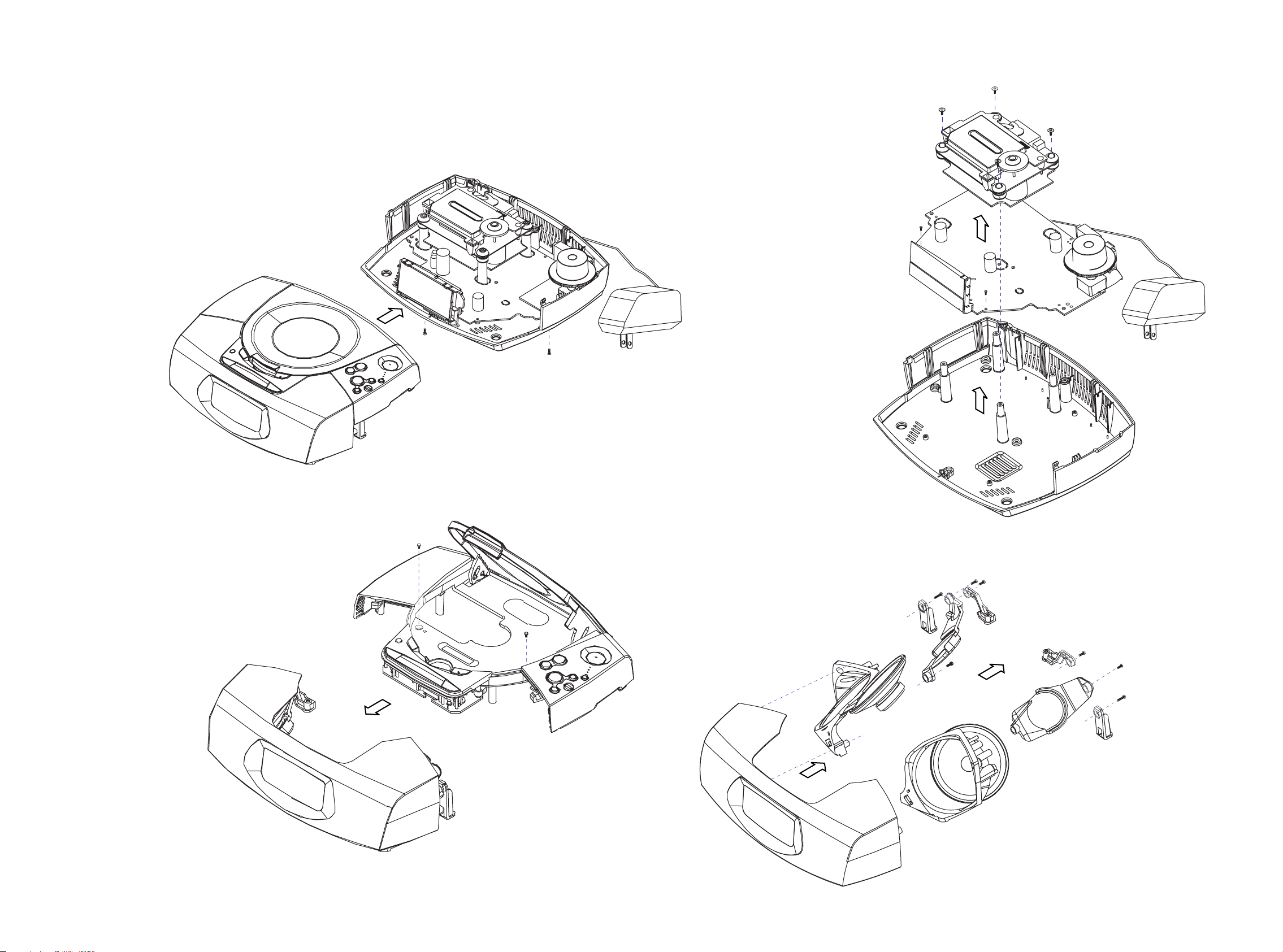
DISASSEMBLY DIAGRAM
(4x)
C3
A. REMOVE BACK CABINET ASSEMBLY
- REMOVE SCREWS A1(3x10) 6 PCS
A1
(6x)
C. REMOVE COMBI BOARD ASSEMBLY
- REMOVE SCREWS C3 (2.5x10) 4 PCS
- REMOVE SCREWS C4 (2x8) 2 PCS
C4
(2x)
B. REMOVE FRONT CABINET ASSEMBLY
- REMOVE SCREWS B2(3x6) 2 PCS
(INSIDE CD DOOR)
B1
(2x)
D. REMOVE LOUDSPEAKER
- REMOVE SCREWS D5 (3x10) 4 PCS
- REMOVE SCREWS D6 (3x10) 2 PCS
- REMOVE SCREWS D7 (3x16) 2 PCS
YD77-4A
D6
(2x)
D5
D7
(4x)
(2x)
4 - 2 4 - 2
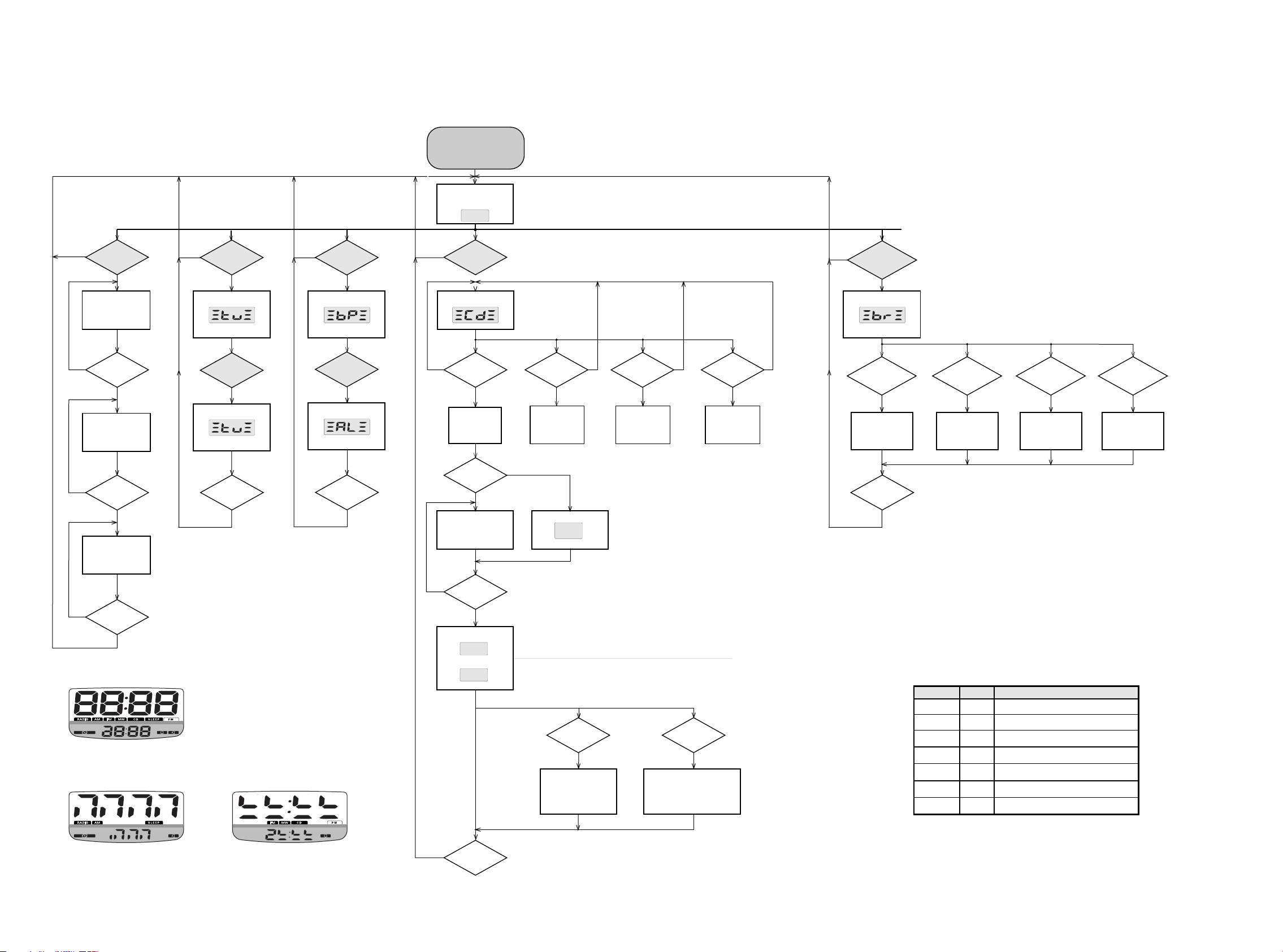
SERVICE TEST PROGRAM
STOP button pressed in any step returns
*
to begin of Service Testprogram.
To leave Service Testprogram disconnect
*
the power supply.
Door switch is ignored → CD door can be opened.
*
To enter Service Test Program
keep ALARM RESET & PLAY
buttons depressed while
power up (plug-in) the set.
DISPLAY TEST BUZZER TESTTUNER TEST
WAKE UP
N
TRACK button
pressed?
Display shows all
segments and flags.
see figure 1
WAKE UP
N
TRACK button
pressed?
Display shows part
segments and flags.
see figure 2
WAKE UP
N
TRACK button
pressed?
Display shows part
segments and flags.
see figure 3
Y
Y
Y
RADIO button
N
Display shows
Switch on radio
RADIO button
N
Display shows
Toggle radio band
STOP button
N
pressed?
Y
pressed?
Y
pressed?
Y
AL1 button
N
pressed?
Display shows
Roger beep tone
AL2 button
N
pressed?
Display shows
Buzzer alarm tone
STOP button
N
pressed?
Display shows
version number
of the µ P - software.
r005
PLAY button
N
pressed?
Y
N
Y
Y
Display shows
PLAY button
pressed?
YY Y Y
FOCUS search
Focus switch on
FOCUS found?
Y
Y
Display shows
Slide servo, Radial servo, Focus servo, Disc motor
and Laser are switched off.
Mute is switched on via decoder IC.
CD SERVO TEST
SLIDE MOTOR test DISC MOTOR test
NN N
DOWN ∞ button
pressed?
Slide moves
inside as long as
button is held
depressed.
N
UP § button
pressed?
Slide moves
outside as long as
button is held
depressed.
Display shows
WAKE-UP
TRACK button
pressed?
Disc motor turns
in play direction
as long as button
is held depressed.
BRIGHTNESS TEST
N
BRIGHTNESS
button pressed?
Y
Display shows
Toggle LED brightness
BRIGHTNESS
button pressed?
Y
Toggle Main
clock light
STOP button
N
pressed?
Y
SET TIME
button pressed?
Y
Toggle Alarm
time light
AL1 button
pressed?
Y
Toggle AL1
Led light
AL2 button
pressed?
Y
Toggle AL2
Led light
-F02
disc motor turns.
N
STOP button
pressed?
Y
AL TIME 1 AL TIME 2
PM
figure 1
AL TIME 1 AL TIME 2
figure 2 figure 3
N
PLAY button
pressed?
Y
Display shows
PLAY
then
Fb:
xx
Auto Adjustment test mode
NEXT button
pressed?
toggle auto-adjustment
display mode
Fb:xx -> Fg:xx
-> Fo:xx -> tb:xx
-> tg:xx -> to:xx
PM
Y
STOP button
pressed?
N
Y
SERVICE PLAY TEST
PLAY button
pressed?
Set is in Service PLAY Mode.
In case of failure, error
codes according to table 1
will be displayed.
N
Y
The SERVICE PLAY MODE intended
to detect and identify the failures in the
CD mode.
In this mode the electronics will still function
even when an error is detected so that
repair activities can be carried out.
Error code
E-00 W
E-01
E-05
E-06
E-20
E-22
E-23
F......Fatal error W......Warning
CD ERROR CODES
Type Error description
Focus error
HF error
W
Jump error
W
Subcode error
W
Focus search erro
F
F
Fatal subcode error
F
Light detection error
table 1
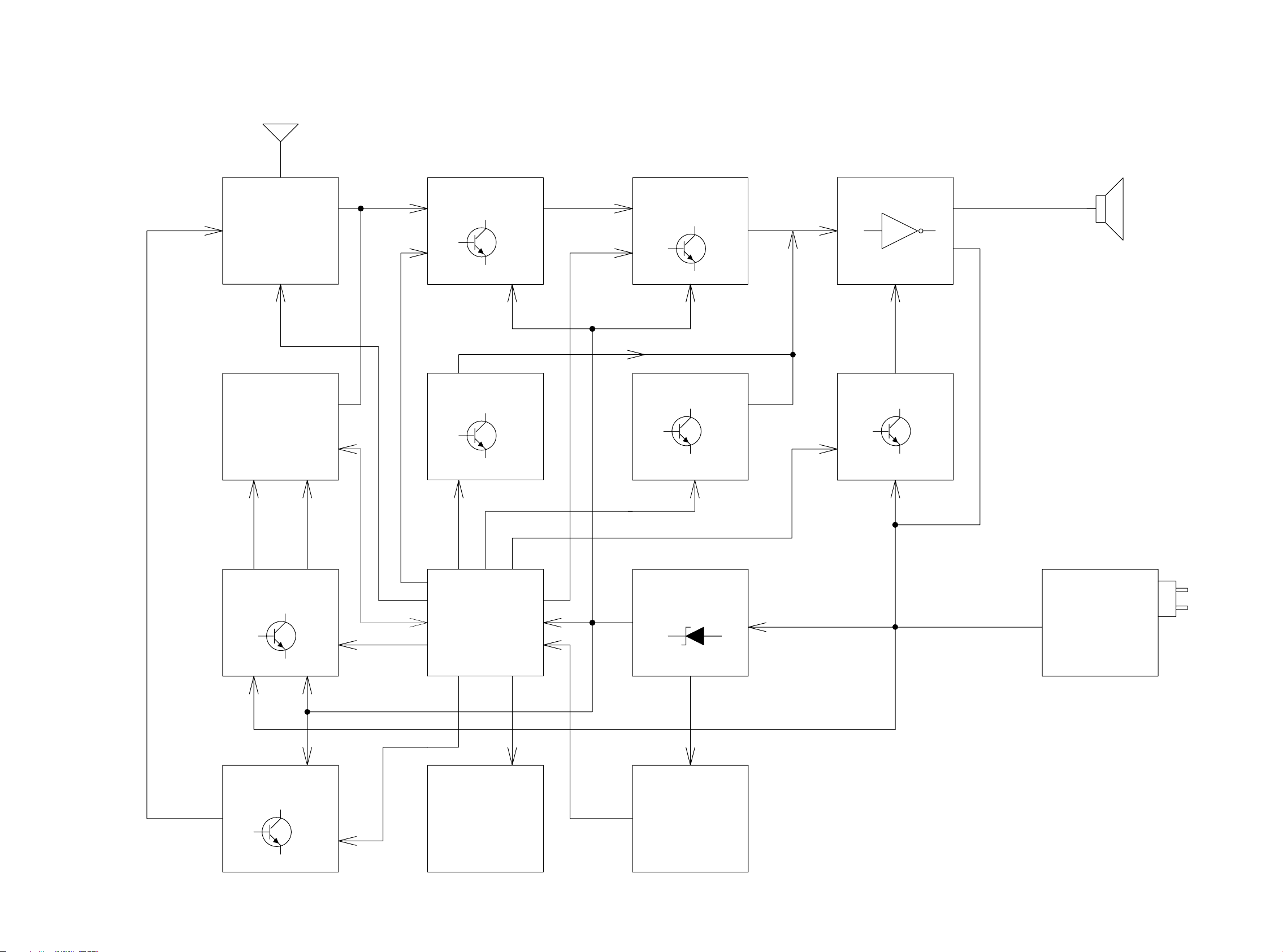
5 - 1 5 - 1
BLOCK DIAGRAM
ANT
ATM5
TUNER
MODULE
AM/FM
ICD01
CD MODULE
SW
PRE-AMP
DBB MUTE PWR ENABLE
BUZZER OUT
VOL-CTRL
PWM
VOL-CTRL
POWER AMP
8 OHM
TDA2822/
TDA2822M
9V
10V 10V5V
CD ENABLE
RADIO ENABLE
5V
CD ENABLE
RADIO ENABLE
TMP86CH21F
MCU
LCD
DISPLAY
5V
VOLTAGE
REGULATOR
5V
KEYBOARD
POWER
ADAPTOR
AC/DC
/00/05 ~230V
/17 ~120V
 Loading...