

Page 1
Media Center MCP9350i
Quick install guide
QIG_MCP9350i_Eng_UK.qxd 01-11-2005 09:21 Pagina 1
Page 2

2
Support
If you need help with your MCP9350i, please visit the Philips support website:
www.P4C.philips.com
If the website does not provide the solution you are looking for, please contact the Philips helpdesk:
UK 0906 1010 017 £ 0.15 / min
QIG_MCP9350i_Eng_UK.qxd 01-11-2005 09:21 Pagina 2
Page 3
3
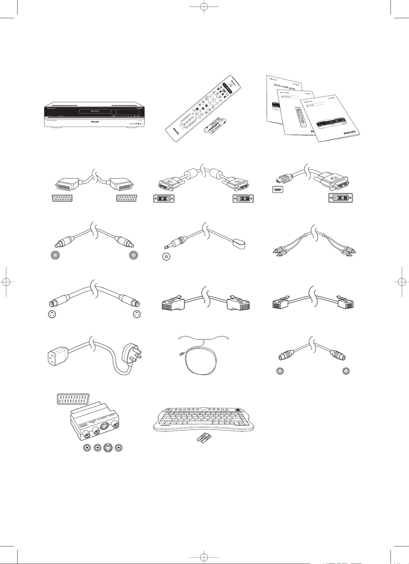
What’s in the box
Media Center MCP9350i Remote control,
2 x AA batteries
SCART cable
DVI-D cable DVI-D to HDMI cable
Quick install guide / Use cases /
RC4370 User manual
Digital audio cinch (coaxial) cable
2 x IR blaster for set-top box Stereo audio cinch cable
S-Video cable
Ethernet cable Telephone cable
Power cable
FM antenna cable TV antenna cable (1 m)
TV antenna cable (10 cm)
Wireless keyboard
3 x AA batteries
SCART to SVHS / CVBS adapter
QIG_MCP9350i_Eng_UK.qxd 01-11-2005 09:21 Pagina 3
Page 4

4
What’s in the box .................................................................. 3
1 Functional overview ......................................................... 5
Front view .............................................................................................................................. 5
Rear view ............................................................................................................................... 6
Remote control ................................................................................................................... 7
Wireless keyboard ............................................................................................................... 9
2 Installing your Philips Media Center ............................ 10
Connecting a TV / monitor ............................................................................................. 10
Connecting video (e.g. set-top box) .............................................................................. 12
Connecting audio ...............................................................................................................13
Connecting to the Internet ............................................................................................. 14
Connecting antennas ......................................................................................................... 16
Inserting batteries in the remote control .................................................................... 16
Connecting to the mains / Switching ON and to standby ...................................... 17
Installing the wireless keyboard ..................................................................................... 18
3 Configuring your Philips Media Center ....................... 19
Microsoft Windows®setup ............................................................................................ 19
Media Center setup wizard ............................................................................................. 19
Manual channel search ...................................................................................................... 24
Additional software setup ................................................................................................ 24
Changing settings ............................................................................................................... 25
Changing screen resolution ............................................................................................. 25
Adjusting aspect ratio ....................................................................................................... 26
4 Additional connections .................................................. 28
Connecting a microphone ............................................................................................... 28
Connecting headphones ................................................................................................... 28
Connecting a video camera (or other portable external source) ......................... 28
Connecting a portable media player (or HDD or photo camera) ........................ 29
Connecting an external drive (HDD, optical drive) .................................................. 29
Inserting memory cards ................................................................................................... 30
5 Important information .................................................. 31
Data loss disclaimer .......................................................................................................... 31
Safety and regulatory information ................................................................................. 31
Contents
Page
QIG_MCP9350i_Eng_UK.qxd 01-11-2005 09:21 Pagina 4
Page 5
5
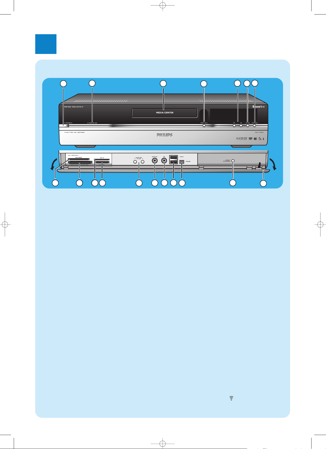
Front view
1
5
8
7
6
8
9
3
13
12
9 10
11
4
14
15
16
17
18
2
1yySTANDBY-ON
Switches the Media Center ON and to standby (lowpower mode).
STANDBY/ON indicator (on the key)
– Lights up orange when the Media Center is connected
to the mains supply.The Media Center is then in lowpower mode, consuming only minimum power.
– Lights up red when the Media Center is switched to
standby with the yyStandby key (1) on the remote
control.
– The indicator is off when the Media Center is swit-
ched on with the y Standby key (1) on the remote
control or the yySTANDBY-ON key (1).
2 RF KEYBOARD LINK
Flashes when the set receives signals from the wireless
keyboard.
3 Optical drive
For playing and burning CDs / DVDs.
4 OPEN/CLOSE //
Opens and closes the optical drive.
5 5
– Searches fast backwards in the current track (keep
pressed).
6
– Searches fast forward in the current track (keep pres-
sed).
– Plays the track in slow motion when the DVD is in
pause mode (press once).
6 STOP 9
Stops playback.
7 PLAY/PAUSE
– Starts playback.
– Pauses playback.
8 SMART MEDIA
For inserting a Smart Media memory card.
9 COMPACT FLASH TYPE 1 / 11, MICRODRIVE
For inserting a Compact Flash memory card.
10 MMC/SD
For inserting an MMC/SD (MultiMedia Card / Secure
Digital card) memory card from a digital camera for
example.
11 MS/MS PRO
For inserting a Memory Stick (Pro).
12 4 HEADPHONE VOLUME 3
Sets the headphones volume. Headphones volume is
independent from set volume.
13 HEADPHONE
For connecting headphones.
14 MIC
For connecting a microphone.
15 USB 2.0
For connecting USB 1.1 and 2.0 enabled devices.
16 FIREWIRE (IEEE1394 / i.LINK) - 4 pins
For connecting digital, FireWire / IEEE1394 / i.LINK enabled, products (e.g. digital camcorders, hard disks, etc.
that require 4-pin connection) to transfer data to the
Media Center.
17 CONNECT RF KEYBOARD
Connects the Media Center with the keyboard.To be
used in combinationwith the key (3) on the keyboard.
18 Flap
1
Functional overview
QIG_MCP9350i_Eng_UK.qxd 01-11-2005 09:21 Pagina 5
Page 6
6
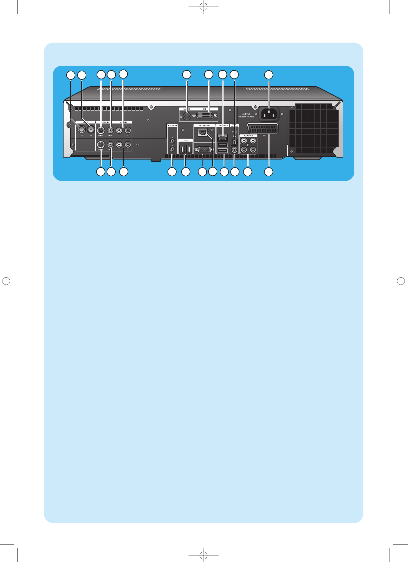
Rear view
364
5
10
15
14
16
18
19
20 21
7 8 9
121113
17
1 2
1 RF IN - FM - Radio
For connecting to the antenna system or to a roofmounted FM antenna (with an impedance of 75 W
(ohm).
2 RF IN - TV
For connecting to the cable antenna system.
3 VIDEO IN 1 - S-Video
Video input socket for connecting to the S-Video output
socket of a TV, cable/satellite set-top box, DVD
player/recorder, etc.
4 VIDEO IN 1 -Video (CVBS)
Video input socket for connecting to the CVBS (composite video) output socket of a TV, cable/satellite set-top
box, DVD player/recorder, etc.
5 AUDIO IN 1
Stereo audio input sockets for connecting to the audio
output sockets of a cable/satellite set-top box, DVD
player/recorder, audio equipment, etc.
6 S-VIDEO OUT
Output socket for connecting to the input socket of
S-Video enabled recording devices (DVD,VCR) or an
S-Video enabled TV.
7 DVI OUT
DVI-D (Digital Video Interface-Digital only) output socket for connecting to the DVI-D input socket of a DVID enabled monitor or flat screen TV.
8 LAN
For connecting to your local area network (LAN).
9 DIGITAL AUDIO - Optical - Out
Optical output socket for connecting to the optical
input socket of a receiver,TV or recording device (CD
recorder,VCR, etc.).
10 AC-INPUT (100-240V - 50/60Hz)
For connecting the Media Center to the mains.
11 VIDEO IN 2 - S-Video
Video input socket for connecting to the S-Video output
socket of a TV, cable/satellite set-top box, DVD
player/recorder, etc.
12 VIDEO IN 2 - Video (CVBS)
Video input socket for connecting to the CVBS (composite video) output socket of a TV, cable/satellite set-top
box, DVD player/recorder, etc.
13 AUDIO IN 2
Stereo audio input sockets for connecting to the audio
output sockets of a cable/satellite set-top box, DVD
player/recorder, audio equipment, etc.
14 IR (infrared) BLASTER (2 x)
For connecting an IR (infrared) blaster in order to select
channels on your cable/satellite set-top box via the
Media Center remote control.
15 1394 (Firewire / i.LINK) - 6-pin(2 x)
For connecting to IEEE 1394 / Firewire / i.LINK compatible peripherals and devices such as an external hard
disk that requires two additional pins for power supply..
16 VGA
For connecting to a VGA (Video Graphics Array) enabled monitor or flat screen TV.
17 MODEM
For connecting the Media Center to a telephone socket
(in order to obtain Internet access).
18 USB 2.0 (2 x)
For connecting USB 1.1 and 2.0 enabled devices.
19 DIGITAL AUDIO - COAXIAL - Out
Coaxial output socket for connecting to the coaxial
input socket of a receiver or recording device (e.g a
DVD recorder).
20 AUDIO OUT (2 x)
Stereo audio output sockets for connecting to the audio
input sockets of a receiver or recording device (e.g a
DVD recorder).
21 SCART (RGB / CVBS)
For connecting to the SCART input connector of a TV.
Note:Wireless LAN antennas (802.11b/g) are already built in in
the set so there is no need for connecting a wireless USB
adapter in order to integrate the Media Center in your
wireless netwerk.
QIG_MCP9350i_Eng_UK.qxd 01-11-2005 09:21 Pagina 6
Page 7
7
C
Remote control
3
1
2
5
4
6
10
9
7
8
12
13
14
17
18
21
20
22
23
16
15
19
11
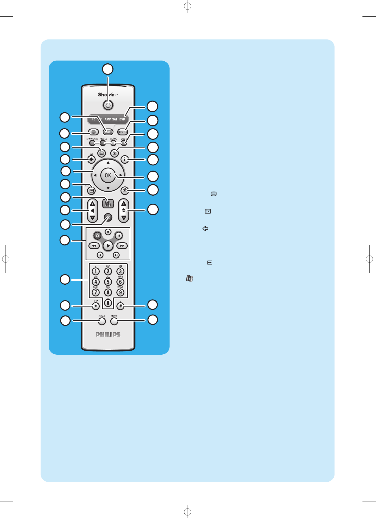
24
In this chapter we will only describe RC key functions in Media
Center (PC) mode. For a desciption of key functions in other
modes (TV,AMP, SAT and DVD), please refer to the RC4370 user
manual.
Notes:
– After switching on the Media Center, the remote control will auto-
matically switch to Media Center mode as well.
– If a key or key combination is pressed for longer than 30 seconds,
the remote control will stop transmitting IR signals.
1yyStandby
Switches the Media Center ON and to standby.
2 SELECT
Selects the device you wish to operate via the remote control.
PC stands for the Media Center.
After switching on the remote control, it will automatically
enter the Media Center mode.
3 Teletext (
)
TV/SAT (in PC mode): text on/off.
4 Guide ( )
Opens the electronic TV program guide.
5 Back ( )
Returns to the previous screen.
6 1 2 3 4
Cursor left, right, up and down keys. Menu navigation keys.
7 MENU ( )
Displays the menu of the DVD currently in the optical drive.
8
Opens Microsoft Windows®XP Media Center edition home
menu.
9 – Volume +
Adjusts the volume of your Philips TV down (–) and up (+).
For adjusting the volume of other TV brands, see the RC4370
User manual.
10 Mute (s)
Mutes headphones output.
11 0 (Record)
Records a TV program and stores it on the Media Center hard
disc drive. By default, recorded programs are stored in the
Shared Documents folder (RecordedTV folder).
9 (Stop)
Stops media currently playing or recording.
; (Pause)
Pauses media currently playing or recording.
5 6 (Search)
Search fast backwards (5) and forward (6) in the current
DVD chapter (keep pressed).
2 (Play)
Plays movie, music or pictures.
¡ ™ (Skip)
Skips the media (video and / or audio) backwards (¡) or forward (™) one music track (CD) or one movie chapter (DVD)
at a time.
QIG_MCP9350i_Eng_UK.qxd 01-11-2005 09:21 Pagina 7
Page 8
8
3
1
2
5
4
6
10
9
7
8
12
13
14
17
18
21
20
22
23
16
15
19
11
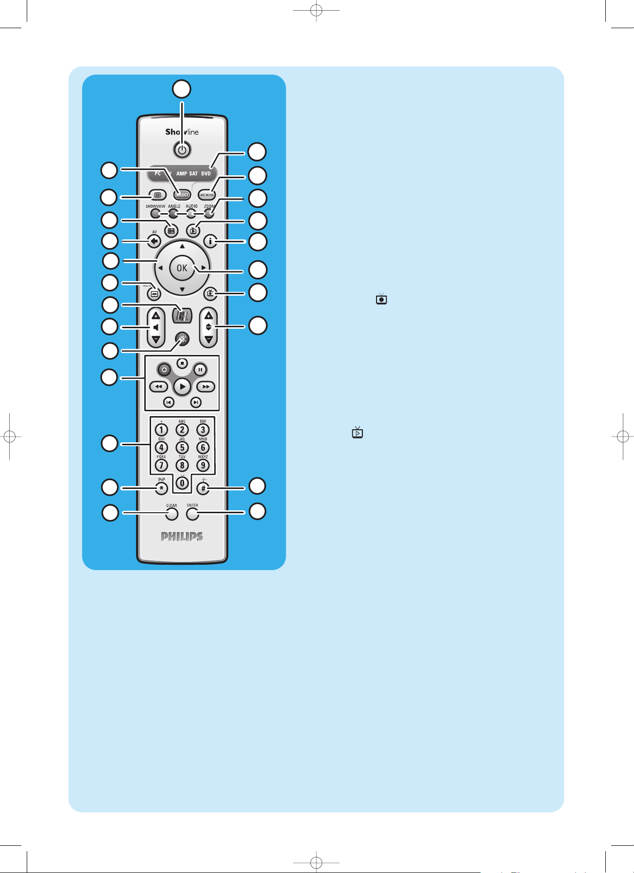
24
12 0 - 9 digit keys
Used to enter numbers or letters (depending on selected
function) that are used to change TV channels, enter text into
a Media Center search or text box, etc.
13 P 1 P (*)
Previous program / channel.
14 CLEAR
Deletes the previous selection you made (functions as the
backspace key on a keyboard).
15 ENTER
Selects desired action or window option.
16 – / – – (#)
Selects between single and double digit program / channel
numbers.
17 – Program +
Program / channel down (–) and up (+).
18 Recorded TV ( )
Shortcut to TV programs, recorded on the Media Center hard
disk.
19 OK
Selects your desired action or window (functions like the
Enter key).
20 i
– Provides information about the currently selected TV pro-
gram.
– Provides extra possibilities within different menus.
21 Live TV ( )
Shortcut for viewing live TV.
22 Red (SHOWVIEW)
Teletext active: red.
Green (ANGLE)
Teletext active: green.
Yellow (AUDIO)
Teletext active: yellow.
Blue (ZOOM)
Teletext active: blue.
23 LIKE MUSIC
Automatically generates a music playlist.
24 Selector window
Indicates which device is selected.
QIG_MCP9350i_Eng_UK.qxd 01-11-2005 09:21 Pagina 8
Page 9
9
Wireless keyboard
3
6
4
5
9
7
8
14
15
1 2 10 11
12
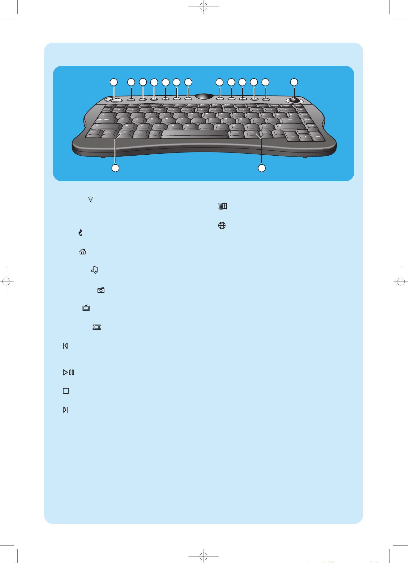
13
1 Left and right mouse keys
2 Connect
Connects the keyboard with the Media Center.To be
used together with the CONNECT RF KEYBOARD
key (17) on the front of the Media Center.
3 Back
Returns to the previous screen.
4Start
Opens the Media Center menu.
5 My Music
Opens the My Music menu of the Media Center.
6 My Pictures
Opens the My Pictures menu of the Media Center.
7 My TV
Opens the My TV menu of the Media Center.
8 My Videos
Opens the My Videos menu of the Media Center.
9
Moves the media (video and/ or audio) backwards one
music track or one DVD chapter at a time.
10
Plays the CD and DVD player, images, music.
11
Stops media currently playing or recording.
12
Moves the media (video and/or audio) forward one
music track or one DVD chapter at a time.
13 Trackball (mouse)
Controls the cursor on the screen.
14
Opens Windows®Start menu.
15
Starts Internet Explorer.
QIG_MCP9350i_Eng_UK.qxd 01-11-2005 09:21 Pagina 9
Page 10
2
Installing your Philips Media Center
10
Connecting a TV / monitor
Your Media Center needs an Internet connection to download the EPG (Electronic Program Guide) and channel frequency information. Make sure that you have access to a dial-up or broadband Internet connection before starting your Media
Center software setup. Contact your Internet service provider for more information about setting up your Internet connection.Also see ‘Connecting to the Internet’.
Your Media Center is equipped with four TV OUT / MONITOR OUT connectors: S-VIDEO OUT (6), DVI OUT (7),
VGA (16) and SCART (21).The DVI (to HDMI) connection is recommended as it offers the highest picture quality. If your
TV is equipped with a CVBS connector, you can use the SCART to SVHS / CVBS adapter to make a CVBS connection.
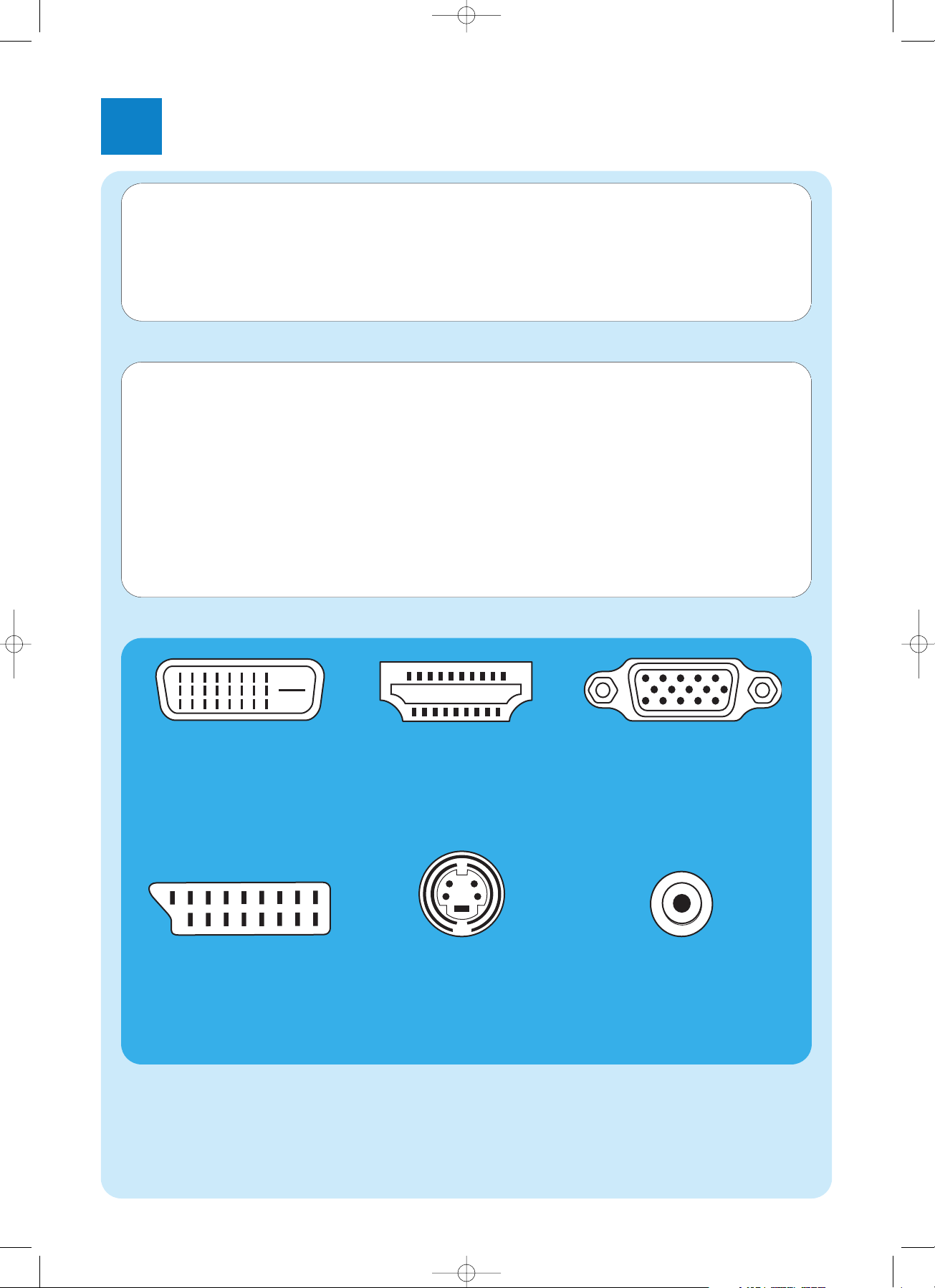
Locate your connector:
Please, first check the type of connector your TV / monitor is equipped with before making any connections.You can locate your
connector in the overview below.The sequence (1-6) also indicates the order of picture quality of the various connectors.
CAUTION! Be sure the Media Center is switched off and disconnected from the mains before making any con-
nections.
Notes:
– Unless indicated otherwise, all Media Center inputs and outputs mentioned are located on the rear of the Media Center.
– First make all required video (TV / monitor) connections, then refer to the ‘Connecting audio’chapter for instructions on how
to make audio connections on the Media Center.
1. DVI-D connector
Recommended. Full resolution and digital connection.
2. HDMI connector
Recommended. Full resolution and digital connection.
3. VGA connector
Full resolution but signal
converts to analog.
4. SCART connector
Limited resolution and
analog connection (RGB: 3
color separation).
5. S-Video connector
Limited resolution and analog connection (RGB: 1
channel modulated).
6. CVBS connector
Only used for recording
from a set-top box.
TV / monitor connectors
QIG_MCP9350i_Eng_UK.qxd 01-11-2005 09:21 Pagina 10
Page 11
11
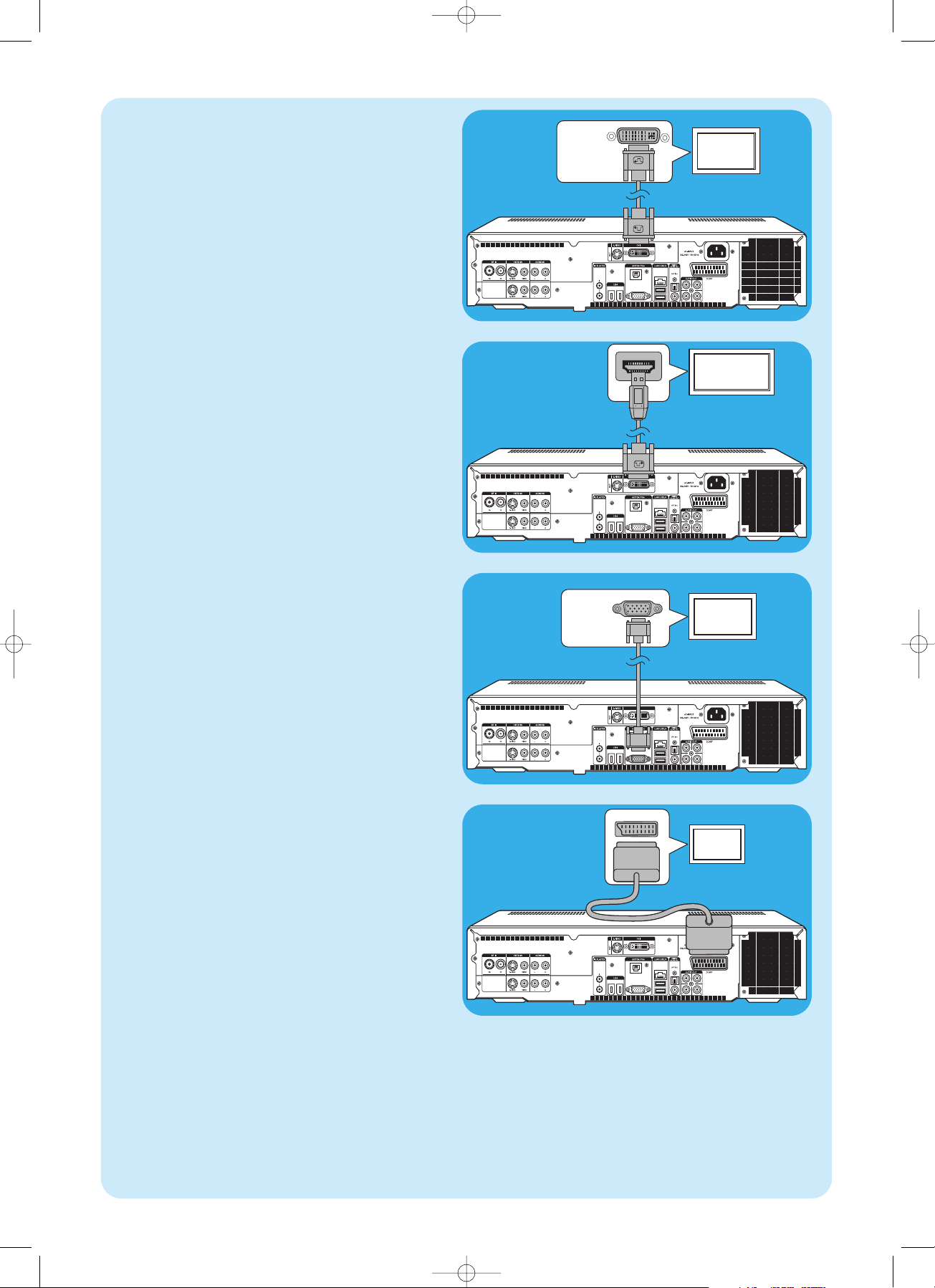
SCART IN
TV / Monitor
(SCART)
4. SCART connection
• Connect the SCART cable between the SCART input
of the TV / monitor and the SCART connector (21) of
the Media Center.
Notes:
– Be sure the SCART connector on your TV supports RGB
(Red, Green, Blue) for optimum picture quality.
– When using normal PC applications, picture quality may not
be optimal.
– When using normal PC applications, picture quality may not
be optimal.
– Some TVs automatically switch between 4:3 and 16:9 image
ratio according to the Wide Screen Signaling information.The
Media Center however does not support Wide Screen
Signaling (WSS). Please consult the User manual that came
with your TV on how to select image ratio manually.
– In case of SCART connection, some small bars might appear
on all sides of the screen.This is not a defect
HDMI
HDMI IN
(HD)TV / Monitor
(HDMI)
2. HDMI connection (recommended)
• Connect the DVI-D to HDMI cable between the
HDMI IN socket of the TV / monitor and the DVI
OUT socket (7) of the Media Center.
• Tighten the screws of the DVI connector.
VGA
Video input
(VGA IN)
TV / Monitor
(VGA)
3.VGA connection
• Connect an VGA cable (not supplied) to the
VGA IN socket the TV / monitor and the VGA output
(17) of the Media Center.Tighten the screws on both
connectors.
Note: If your VGA TV / monitor is equipped with a fixed VGA con-
nection cable, simply plug this cable into the VGA output
(17) of the Media Center and tighten the screws.
DVI
Video input
(DVI-D IN)
TV / Monitor
(DVI-D)
1. DVI-D connection (recommended)
• Connect the DVI-D cable between the DVI-D IN soc-
ket of the TV /monitor and the DVI OUT socket (7) of
the Media Center.Tighten the screws on both connectors.
Note: If your DVI-D TV / monitor is equipped with a fixed DVI-D
connection cable, simply plug this cable into the DVI
OUT socket (7) of the Media Center and tighten the
screws.
SCART
QIG_MCP9350i_Eng_UK.qxd 01-11-2005 09:21 Pagina 11
Page 12

12
Video equipment
SCART OUT
SCART
ADAPTER
SCART connection
If your video equipment is only equipped with a SCART
output, you can use the SCART to SVHS / CVBS adapter to
connect the equipment to the Media Center.
1 Connect the SCART to SVHS / CVBS adapter to the
SCART connector of the video equipment.
2 Connect an CVBS cable (not supplied) between the yel-
low video connector of the adapter and the CVBS
input (4, 12) of the Media Center.
OR:
2 Connect the S-Video cable between the S-Video con-
nector of the adapter and one of the S-Video inputs
(VIDEO IN 1 - 3, VIDEO IN 2 - 11) of the Media
Center.
3 Connect the stereo audio cinch cable between the red
and white audio connectors of the adapter and the corresponding AUDIO outputs (5, 13) of the Media
Center.
Note: Upon using the S-Video connection, the picture may be
black & white.To solve this problem make sure that the
video equipment uses S-Video as output. For this see the
User manual that came with your video equipment.
SCART / CVBS
Connecting video (e. g. set-top box)
Video equipment
S-VIDEO
OUT
AUDIO
OUT L/R
S-Video connection
S-Video connection offers the best picture quality.
1 Connect the S-Video cable between the
S-VIDEO OUT socket of the video equipment and
one of the S-VIDEO IN sockets (3, 11) of the Media
Center.
2 Connect the stereo audio cinch cable between the
AUDIO OUT L/R sockets of the video equipment
and the AUDIO IN L/R sockets (5 or 13) of the
Media Center.
S-Video
Video equipment
SCART OUT
SCART
ADAPTER
SCART / S-Video
S-Video
Video input
(S-VIDEO IN)
TV / Monitor
(S-Video)
5. S-Video connection
• Connect the S-Video cable between the
S-VIDEO IN socket of the TV / monitor and the
S-VIDEO OUT socket (6) of the Media Center.
Note:When using normal PC applications, picture quality may
not be optimal.
QIG_MCP9350i_Eng_UK.qxd 01-11-2005 09:21 Pagina 12
Page 13

13
Connecting audio
Digital
OPTICAL IN
Receiver /
Recording device
COAXIAL IN
Receiver /
Recording device
Digital optical audio connection
• Connect a digital optical cable (not supplied) between
the OPTICAL IN socket of the monitor,TV, receiver
or recording device and the DIGITAL OPTICAL
output (9) of the Media Center.
Digital coaxial audio connection
• Connect the digital coaxial cable between the COAXI-
AL IN socket of the monitor,TV,receiver or recording
device and the DIGITAL COAXIAL output (19) of
the Media Center.
Receiver /
Recording device
L
AUDIO IN
R
Analog audio connection
• Connect the stereo audio cinch cable between the
AUDIO IN L/R sockets of the monitor,TV, receiver or
recording device and the AUDIO OUT L/R sockets
(20) of the Media Center.
Analog
IR
Set-top box
Connecting an IR-blaster
1 Remove the adhesive tape from the infrared sensor of
the IR blaster.
3 Place the IR blaster in front of the IR receiver eye of
the cable / satellite set-top box.
4 Connect the IR blaster cable to one of the IR
BLASTER outputs (14) of the Media Center.
> You can now select channels on your cable/satellite set-top
box, using the Media Center remote control.
IR-blaster
QIG_MCP9350i_Eng_UK.qxd 01-11-2005 09:21 Pagina 13
Page 14

14
Telephone socket
Dial-up modem
Dial-up modem connection
1 Make sure the dial-up modem is connected to the tele-
phone network.
2 Connect the telephone cable between the telephone
socket and the MODEM connector (17) of the Media
Center.
• For settings, contact your Internet service provider.
LAN
Ethernet (LAN)
Router / DSL modem
Ethernet connection
• Connect the ethernet cable between the router/DSL
modem and the LAN connector (8) of the Media
Center.
• For settings, contact your Internet service provider.
Connecting to the Internet
The Media Center requires an Internet connection to access the Internet. Make sure you have access to a dial-up or
broadband Internet connection before starting Media Center software setup. Contact your Internet service provider for
more information about setting up your Internet connection.
The Media Center offers three possible ways for connecting to the Internet:
1 via the ethernet cable to a DSL (Digital Subscriber Line) modem (if you have a wired network);
2 via the telephone cable to connect to the telephone line (if you have a dial-up modem);
3 wireless connection to a DSL (Digital Subscriber Line) modem (if you have a wireless network).
If you connect (either wired or wireless) the Media Center to an existing home network with centrally shared broadband
Internet access for all connected computers, you can connect the Media Center directly to your central network device
(the router/gateway). In this way, the Media Center can access the Internet just like your other computers and you do not
need to install ICS (Internet Connection Sharing) to make Internet access available to your Media Center.
QIG_MCP9350i_Eng_UK.qxd 01-11-2005 09:21 Pagina 14
Page 15

15
Internet
Wireless connection
Wireless base stations (and wired Internet gateway routers) share their broadband Internet access automatically
within the network.
Notes:
–We strongly recommend the use of an encryption key to
protect your network against intruders.
– Wireless LAN antennas (802.11b/g) are already integrated
in the set so there is no need for connecting a wireless USB
adapter in order to integrate the Media Center in your wireless netwerk.
1 Check your existing wireless network settings to enter
them upon request during Media Center setup.
Determine the wireless network name (SSID) and the
encryption key(s) you used for securing your wireless
network.
Wireless Network Name (SSID - Service Set
Identifier):
Usually, you can find the wireless network name in the
options menu of your wireless network adapter or
wireless base station.To check this, open the program
that came with your network adapter.
Encryption key:
The wireless encryption key can be either a WEP code
or a WPA code.
WEP (Wired Equivalent Privacy) provides basic protection for home networks and uses 64- or 128-bit
encryption keys.
- 64-bit: 5 characters ASCII, or 10 characters HEX, or
- 128 bit: 13 characters ASCII, or 26 characters HEX.
WPA (Wi-Fi Protected Access) offers up to 256-bit
encryption keys, which are much harder to decode than
WEP encryption keys.
WPA increases the level of data protection and access
control for wireless networks.
Note: Both network name (SSID) and encryption key are case
sensitive, meaning that ‘ABC’ is not the same as ‘aBc’.
Always input characters in the correct case to avoid problems.
2 Write down your encryption key(s) and SSID.You may
need them when installing the Media Center.
3 Upon request enter your SSID and encryption key to
add the Media Center to the wireless network. Refer to
the base station (wireless access point) user manual for
details.
Wireless
QIG_MCP9350i_Eng_UK.qxd 01-11-2005 09:21 Pagina 15
Page 16

16
Radio antenna connection
1 Connect a coaxial cable (not supplied) to the RF IN
FM connector (1) of the Media Center.
2 Connect the other end of the cable to the cable anten-
na system.
If your are not connected to a cable antenna system, you
can use the FM cable.
1 Connect the FM cable to the RF IN FM (1) connector
of the Media Center.
2 Position and vary the direction of the FM antenna until
you find the strongest reception.Then secure the antenna in that position.
Wallsocket
10cm
TV antenna connection
1 Disconnect the TV antenna cable from the cable anten-
na system.
2 Connect the 10 cm TV antenna cable to the RF IN TV
socket (2) of the Media Center and to the cable
antenna system.
Connecting antennas
1 Remove the battery compartment cover and insert two
AA (1.5 V) batteries, noting the + and – configuration in
the battery compartment.
2 Replace the cover.
Inserting the batteries in the remote control
2 x
QIG_MCP9350i_Eng_UK.qxd 01-11-2005 09:21 Pagina 16
Page 17

17
Connecting to the mains
After connecting all desired equipment as described, you
can connect the Media Center to a wall socket.
1 Make sure all connections have been made before con-
necting the Media Center to the mains supply.
2 First connect the mains lead to the AC-INPUT (10) and
then to a wall socket.
> The Standby/On indicator (on the STANDBY-ON key 1)
lights up orange.
> The Media Center is now in low power mode, consuming
only a minimum amount of power.
Switching ON
• To switch on the Media Center from low-power mode,
press the y STANDBY-ON key (1) on the front of
the Media Center.
> The Standby/On indicator (1) goes out.
• Press the y STANDBY-ON key (1) again to put the
Media Center back to low-power mode.
Switching to standby
• When the Media Center is switched on (Standby/On
indicator out), press the y Standby key (1) on the
remote control to place the Media Center in standby
mode.
> The Standby/On indicator (1) lights up red.
• To switch the Media Center on again from standby
mode, press the y Standby key (1) on the remote
control again or the y STANDBY-ON key (1) on the
front of the Media Center.
> The Standby/On indicator (1) goes out.
Note: In both low-power and standby mode the Media Center is
still consuming some power.To disconnect the Media
Center from the mains supply completely, disconnect the
mains lead from the wall socket.
Connecting to the mains / Switching ON and to standby
QIG_MCP9350i_Eng_UK.qxd 01-11-2005 09:21 Pagina 17
Page 18

18
1 Remove the battery compartment cover and insert
three AA (1.5 V) batteries, noting the + and – configuration in the battery compartment.
2 Replace the cover.
3 Make sure the Media Center is connected to the mains.
4 Press the y STANDBY-ON key (1) to switch on the
Media Center.
> The Standby/On indicator (on the STANDBY-ON key 1)
goes out.
5 Press the CONNECT RF KEYBOARD key (17) on
the Media Center.
6 Press the key (1) on the keyboard.
> The Media Center is now able to receive commands from
the wireless keyboard.
Note:When not used for 5 minutes, the keyboard switches to
standby.You can activate the keyboard again by pressing
any key except the left and right mouse keys (1) and the
trackball (13).
Installing the wireless keyboard
3 x
QIG_MCP9350i_Eng_UK.qxd 01-11-2005 09:21 Pagina 18
Page 19

19
3
Setup of your Philips Media Center
To setup Windows for the first time:
Follow the on-screen instructions for the initial Microsoft
Windows setup.
1 Click Next to set up your system.
2 Select your country/region and language.
3 Select your time zone.
4 Read the End Users License Agreement.Select ‘Yes, I
accept’ to accept.
5 Select a computer name.A default name is already filled
in.You are free to accept this name or to enter any
other name. E.g. ‘Our family Media Center’.
6 Click Next if your computer is not part of a domain.
If your Media Center will be part of a domain, select
Ye s and enter the name of this domain.
7 Select Finish.
Microsoft Windows®setup
After switching on your Media Center for the first time, the initial Microsoft Windows setup screen is displayed. Follow
the on-screen instructions to complete this setup.
Notes:
– Before switching on the Media Center, be sure to switch on your monitor or TV first and select a channel for the Media Center
on your TV.
– Please use your wireless keyboard with integrated trackball to navigate the screens. Make your selection with the cursor and
click Next.
– If there is no wireless connection between keyboard and Media Center: press the CONNECT RF KEYBOARD key (17) on
the Media Center and the ( ) key (2) on the keyboard.
Media Center setup wizard
Required Setup
Media Center setup wizard guides you through the initial
setup of the Media Center, including the steps required for
your network connection and your broadband connection.
Follow the on-screen instructions to complete this setup.
Notes:
– Please use your wireless keyboard with integrated trackball
(13) to navigate the screens.
– Make sure the following physical connections are established
for your Media Center:
- Internet;
- TV- and radio signal;
- network connection (if your Media Center will be part of a
network);
- set-top box connection (if you are using a set-top box).
After finishing the initial Microsoft Windows setup,Windows restarts automatically and the Media Center setup
wizard is displayed.
QIG_MCP9350i_Eng_UK.qxd 01-11-2005 09:21 Pagina 19
Page 20

20
The Welcome screen of Media Center setup wizard is displayed.
1 Click Next.
> Media Center Setup required and optional setup informa-
tion is displayed.
2 Click Next.
> Media Center Privacy Policy information is displayed.
3 Click Next.
> Enhanced Playback screen is displayed.
4 Follow the on-screen instructions, make your selection
and click Next.
> Join Wireless Network screen is displayed.
5 For connection of your Media Center to a wireless net-
work select Ye s and click Next.
• Select ‘Enter my network name manually’ and
click Next.
• Select your network name in the list and click Next.
• Select Finish to exit.
OR:
If your network name is not listed:
• Select ‘Not listed’ and click Next.
• Enter your network name and click Next.
• If your network is protected, select Yes and click
Next.
• Enter your network key (WEP or WPA) and click
Next.
Note:The encryption key is case sensitive, meaning that ‘ABC’ is
not the same as ‘aBC’.
6 If you have a permanent connection to the Internet
(‘always on’ DSL or cable connection) selectYe s and
click Next.
7 Click Test to test your Internet connection.
• If your connection is not working, check:
- connectors and cables;
- check your router settings;
- contact your Internet service provider.
Optional setup
In the optional setup procedure you can customize your Media Center.The setup wizard enables you to:
– configure tuners,TV signal, and TV program guide information;
– select and adjust Media Center display settings;
– setup of speakers;
– control of your set-top box.
Media center installation with a Sky set-top box
Configure Tuners,TV Signal and Guide
1 Confirm Your Region
• Check Current Region is correct and follow on-screen instructions
2 Automatic TV Signal Setup
• Select ‘I will manually configure my TV signal’
3 • Select Your TV Signal
• If you are using a set-top box, select ‘Satellite’
4 • Select Your TV Signal Type
• Select ‘Analog Terrestrial (PAL/SECAM)’
5 Which Tuners Do You Want to Configure?
If you are using one set-top box please tick check ‘NVIDIA DualTV Tuner’ only
If you wish to connect two set-top boxes to your Showline PC Media Center also tick check ‘NVIDIA DualTV Tuner 2’
QIG_MCP9350i_Eng_UK.qxd 01-11-2005 09:21 Pagina 20
Page 21

21
6 Prepare For Set-top Box Setup
• Follow on-screen instructions
7 Select A Working TV Signal
• Follow on-screen instructions
8 Set-top Box Remote
• Follow on-screen instructions
9 Identify Set-top Box Remote
• Follow on-screen instructions
10 Set-top Box Remote Identified
• Follow on-screen instructions
11 Select Number of Digits
• UK set-top boxes operate with three digits
12 How Do You Change Channels?
• Select ‘No, I just enter the channel number’
13 Test Channel Changing
• Follow on-screen instructions
> If you experience any difficulties please contact us on 0906 1010 017
14 Set IR Signal Speed
• Follow on-screen instructions
15 IR Signal Speed Set
• This page is for information
16 Guide Privacy
• Select ‘Ye s ’
17 Guide Terms Of Service
• Follow on-screen instructions
18 Enter Your Post Code
• Follow on-screen instructions
19 Download Provider Information
• Please wait for download to complete before clicking ‘Next’
20 Select TV Signal Provider
• Select Sky Digital BBC London/ITV London
21 Download TV Program Guide Information
• Showline will now download TV information
Media center installation from a tv signal
Configure Tuners,TV Signal and Guide
1 Confirm Your Region
• Check Current Region is correct and follow on-screen instructions
2 Automatic TV Signal Setup
• Select ‘I will manually configure my TV signal’
3 Select Your TV Signal
• Select ‘Antenna’
4 Select Your TV Signal Type
• Analog Terrestrial (PAL/SECAM)
5 Which Tuners Do You Want to Configure
•Tick both boxes tuners if you wish to be able to watch one channel whilst you record another
6 Guide Privacy
• Follow on-screen instructions
7 Guide Terms of Service
• Follow on-screen instructions
8 Enter Your Postal Code
• Follow on-screen instructions
9 Download Provider Information
• Follow on-screen instructions
10 Select TV Signal Provider
• Select 'Analogue terrestrial – all channels'
11 Download TV Program Guide Information
• Follow on-screen instructions
QIG_MCP9350i_Eng_UK.qxd 01-11-2005 09:21 Pagina 21
Page 22

22
The Showline PC will tune all available channels.When complete …
• Press the green start button in the centre of the remote control to access the media centre menu.
• Select Settings,TV, Guide, and Edit channels. From this screen it is possible to view each channel the media centre has
installed.
• Please review the channels one by one and untick any which have a poor or non existent picture.This will ‘block’ these
channels.When you have finished please save your selection.
• Return to the Guide menu and select Change Channel Order.The change channel menu lists the channels installed by
the Media center. Channels marked as ‘blocked’ have a poor or non existent picture.
• Follow the instructions on screen to place the channels in the order you wish to view them. For example, Channel 1 for
BBC1.
Media center installation with a Freeview set-top box
Configure Tuners,TV Signal and Guide
1 Confirm Your Region
• Check Current Region is correct and follow on-screen instructions
2 Automatic TV Signal Set-up
• Select ‘I will manually configure my TV signal’ and then click ‘Next’
3 Select Your TV Signal
• If you are using a set-top box, Select ‘Cable or digital cable’ and then click ‘Next’
4 Select Your TV Signal Type
• Select ‘Analog Terrestrial (PAL/SECAM)’
5 Do You Have A Set-top Box?
• Select ‘Ye s ’
6 Which Tuners Do You Want To Configure?
• If you are using one set-top box please tick check ‘NVIDIA DualTV Tuner’ only
• If you wish to connect two set-top boxes to your Showline PC also tick ‘NVIDIA DualTV Tuner 2’
7 Prepare for Set-top Box Setup
• Follow on-screen instructions
8 Select A Working TV Signal
• Follow on-screen instructions
9 Set-top Box Remote
• Follow on-screen instructions
10 Identify Set-top Box Remote
• Follow on-screen instructions
11 Set-top Box Remote Identified
• Follow on-screen instructions
12 Select Number of Digits
• UK Set-top boxes operate with three digits
13 How Do You Change Channels?
• Select ‘No, I just enter the channel number’
14 Test Channel Changing
Using the IR blaster with your set-top box. Follow on-screen instructions. If the channel does not change try selecting
‘Try next IR control cable’ and repeat.
> If you experience any difficulties please contact us on 0906 1010 017
If channels do not change correctly…
Change Channel Entry Method
• Select ‘I am certain the channel entry method is correct’
Learn Set-top Box Remote
• Select ‘Learn set-top box codes’
15 Set IR Signal Speed
• Follow on-screen instructions
16 IR Signal Speed Set
• This page is for information
17 Set Up Your TV Program Guide
• This page is for information
18 Guide Privacy
For ‘Quick Start’ we recommend you select ‘No’.
If you choose to install the guide you will need to re-name and re-order the channels (see main instructions for use).
QIG_MCP9350i_Eng_UK.qxd 01-11-2005 09:21 Pagina 22
Page 23

23
Optimize how the Media Center looks on your display
This option enables you to adjust display settings.
1 Select your display type.
2 Select the connection type of your display.
Note: If you are using the SCART output (21) of the Media Center, select Component (YpbPr).
3 Adjust display settings to your personal preferences in Display Calibration.
Note: If you select a wrong display setting the screen may turn black. Please wait for about 15 seconds, then the on-screen infor-
mation will be be visible again.
Setup your speakers
This option enables you to specify and test your speaker configuration.
• Always select the 2 speakers option since the Media Center offers analog stereo output only.
If you are using the digital audio connection:
After finishing the Media Center setup wizard, follow the instructions below:
1 Press the key (8) on the remote control.
> The Media Center Start menu appears.
2 Select More Programs and press the OK key (9)
3 Select DVD Settings and press the OK key (9)
4 Select Audio Settings and press the OK key (9)
5 Select SPDIF and press the OK key (9)
6 Select Save and press the OK key (9)
> After finishing the Optional Setup procedure, the Media Center’s Start screen is displayed and your Philips Media Center is
ready for use.
Note: S/PDIF (Sony/Philips Digital Interface) is a standard audio transfer file format, usually found on digital audio equipment or audio
processing devices. It allows the transfer of audio from one file to another without the conversion to and from an analog format,
which could degrade the signal quality.
QIG_MCP9350i_Eng_UK.qxd 01-11-2005 09:21 Pagina 23
Page 24

24
Philips Media Manager add on transcoder
Philips Media Manager (PMM) makes the music, photo, and movie files on your computer available for transfer from
your computer to your television and audio system.
The Media Center uses the new DVR-MS file format when recording video. DVR-MS stands for Digital Video Recorder-
Microsoft®.The video contained in a DVR-MS file is encoded as MPEG-2 video stream.A DVR-MS file can also be copy protected, allowing playback only on the Media Center.
The PMM and PMM add on transcoder modules work together to enable you to stream Media Center content to a
Philips Streamium Client.
We advise you to install these modules only when you intend to use the PMM / PMM add on transcoder feature.
• To se tup PMM, double click the PMM icon ( ) and follow the on-screen instructions.
• To install PMM add on transcoder, double click the s icon ( ) and follow the on-screen instructions.
Manual channel search
1 Press the key (8) on the remote control.
2 Select Settings and press the OK key (19) on the
remote control.
3 Select TV, then TV Signal Setup and press the OK
key (19).
4 SelectYe s in the TV Signal Setup inset window.
5 Select Start Scan and press the OK key (19).
> The scanning for TV channels starts.
6 Select Next and then Finish when scanning is
completed.
For automatic channel search, see ‘TV Guide function - Seeking a TV program’ in the use cases.
Additional software setup
Norton
The Norton Internet Security module provides essential protection from viruses,hackers, and privacy threats. Norton
Internet Security includes a firewall and other powerful tools to safeguard your system.The firewall automatically turns back
on after a period of being temporarily switched off.With the most recent version you can prevent certain Internet worms
from entering your system.You can stop e-mail addresses from being sent to Web sites without your permission,and you
can control which sites track your activities with Internet cookies.You can also block banner ads and pop-up windows.The
Norton installer is started up automatically when the Media Center is switched on for the first time.All you have to do is
follow the on-screen instructions.
QIG_MCP9350i_Eng_UK.qxd 01-11-2005 09:21 Pagina 24
Page 25

25
After you have completed the initial setup procedure with the Media Center setup wizard, changing of settings is
always possible. Steps you have skipped during initial setup can also be completed.
Changing settings
1 Press the key (8) on the remote control.
> The Media Center Start menu appears.
2 Select Settings.
3 Press the OK key (19).
You have access to Settings-submenus for:
- General Media Center settings
- TV
- Pictures
- Music
- DVD
- Messenger and Caller ID
- Radio
- Help
Changing screen resolution
An important example of changing your Media Center’s settings is the change in screen resolution.
1 Press the key (8) on the remote control.
2 Select Settings and press the OK key (19).
3 Select Media Center Setup in the Settings
(General) window and press the OK key (19).
4 Select Configure Your TV or Monitor in the Media
Center Setup settings window and the OK key (19).
5 Follow the on-screen instructions and select Display
type and Connection type.
Note: If you are using the SCART output (21) of the Media
Center, select Component (YpbPr).
6 Select Adjust Display Controls in the Adjust Your
Display Settings window and the OK key (19).
7 Select Next and press the OK key (19) to display the
list of controls in the Display Calibration window.
8 Select Aspect Ratio (Shape) and press the OK key
(19).
9 Select Change Screen Resolution, press the OK key
(19) and select Ye s in the inset window.
10 Use your keyboard and mouse to set the new resoluti-
on in the Windows XP Display Properties window that
appears.
11 When finished click the maximize key in the upper right
corner of the Media Center window to return to the
fullscreen display of the Media Center window.
QIG_MCP9350i_Eng_UK.qxd 01-11-2005 09:21 Pagina 25
Page 26

26
Adjusting aspect ratio
Aspect ratio is the relation between width and height of an image.The aspect ratio of the screen of a standard computer
monitor and CRT (Cathode Ray Tube) TV set is 4:3. The 4 means 4 units wide, and the 3 means 3 units high.
High-definition TV (HDTV) format is 16:9.
Your TV,TV content (video or DVD played on your TV) and Media Center may have different aspect ratios, resulting in
horizontal or vertical bars on your screen. If this is the case, refer to the information below on how to adjust the aspect
ratio in various situations.
Resolution: 720 x 576.
SCART connected.
Standard (CRT)
TV / monitor
Resolution: 720 x 576.
SCART connected.
Standard (CRT)
TV / monitor
Resolution that gives a 16:9
aspect ratio (e.g.: 1280 x 720
or 1920 x 1080). DVI,VGA or
HDMI connected.
Flat screen TV /
monitor (plasma or
LCD)
Standard screen
(No video or
DVD is played)
Video or DVD
with a 4:3 aspect
ratio is played
Video or DVD
with a 16:9
aspect ratio is
played
No bars.Aspect ratio
correct. No action
required.
Vertical bars. See A. No bars.Aspect ratio correct.
See D.
No bars.Aspect ratio
correct. No action
required.
Vertical bars. See B. Vertical bars. See B.
Horizontal bars. See C.
No bars.
Aspect ratio correct.
1
No bars.Aspect ratio correct.
No action required.
2
QIG_MCP9350i_Eng_UK.qxd 01-11-2005 09:21 Pagina 26
Page 27

27
A
Vertical bars on standard screen (no video or DVD
is played):
• Minimize / remove bars by adjusting the aspect radio of
your TV.For this see the User manual that came with
your TV.
Note:Aspect ratio of the displayed image will be distorted.
B
Vertical bars when playing 4:3 video or DVD on 16:9
TV (monitor):
In this situation vertical bars on both sides are normal and
cannot be minimized / removed without distorting the
aspect ratio of the displayed image.Adjust the aspect ratio
of the played content (video or DVD).
1 Press the i key (20) on the remote control.
2 Select Zoom and press the OK key (19).
3 Select the best aspect ratio option for your situation
(1, 2 or 3).
C
Horizontal bars when playing 16:9 video or DVD on
4:3 TV (monitor):
In this situation horizontal bars on both sides are normal
and cannot be minimized / removed without distorting the
aspect ratio of the displayed image or without displaying
only part of the image.Adjust the aspect ratio of the played
content (video or DVD).
1 Press the i key (20) on the remote control.
2 Select Zoom and press the OK key (19).
3 Select the best aspect ratio option for your situation (1,
2 or 3).
D
• Adjust the Media Center graphic settings to a 16:9
resolution that gives the best picture quality on your
specific TV / monitor. 1280 x 720 or 1920 x 1080 are
most commonly supported by flat screen TVs / monitors.
1 – If vertical bars appear: adjust aspect ratio of your TV.
– If horizontal bars appear: adjust aspect ratio of the played content (video or DVD) as decribed under B and C.
– ‘Wide screen’ content (e.g. DVDs) is not always recorded with a 16:9 aspect ratio but slightly different. If this is the case,
small horizontal bars might still appear.
2 ‘Wide screen’ content (e.g. DVDs) is not always recorded with a 16:9 aspect ratio but slightly different. If this is the case,
small horizontal bars might still appear.
QIG_MCP9350i_Eng_UK.qxd 01-11-2005 09:21 Pagina 27
Page 28

28
4
Additional connections
1 Connect headphones with a 3.5 mm jack to the
HEADPHONE socket (13) on the front of the Media
Center.
2 Set the headphone volume with the
4 HEADPHONE VOLUME 3 keys (12).
• You can mute the headphones sound with the Mute
(s) key (10) on the remote control.
Connecting headphones
Video
camera
• Connect the Firewire (IEEE1394 / i.LINK) connector
of your camera to the FIREWIRE (IEEE1394 / Firewire
/ i.LINK) connector (16) on the front of the Media
Center. For this use a 4-pin firewire (IEEE1394 / i.LINK)
cable (not supplied).
OR:
• Connect the USB connector of your camera to the
USB 2.0 input (15) on the front of the Media Center.
For this use a USB 2.0 cable (not supplied).
Notes:
– Be sure to connect the camera to the Media Center before
starting the DV Capture program.
– Be sure to exit the DV Capture program before disconnec-
ting the camera.
– Please check to see if additional software is required to sup-
port your device. Install the drivers that came with your device before connecting the device to the Media Center. For
this, see the user manual of the device.
Connecting a video camera (or other portable external source)
• Connect a microphone to the MIC input (14) on the
front of the Media Center.
Connecting a microphone
QIG_MCP9350i_Eng_UK.qxd 01-11-2005 09:21 Pagina 28
Page 29

29
External HD
Input
External HD
• Connect the Firewire (IEEE1394 / i.LINK) connector
of your external drive to the FIREWIRE (IEEE1394 /
i.LINK) connector (15) on the rear of the Media
Center. For this use a 6-pin firewire (IEEE1394 / i.LINK)
cable (not supplied).
OR:
• Connect the USB connector of your external drive to
the USB 2.0 connector (18) on the rear of the Media
Center. For this use a USB 2.0 cable (not supplied).
Note: Please check to see if additional software is required to
support your device. Install the drivers that came with your
device before connecting the device to the Media Center.
For this, see the user manual of the device.
Connecting an external drive (HDD, optical drive)
Por ta ble
Media
Player
• Connect the Firewire (IEEE1394 / i.LINK) connector
of your portable media player (e.g. an MP3 player, Hard
Disk Drive or photo camera) to the FIREWIRE
(IEEE1394 / i.LINK) connector (16) on the front of the
Media Center. For this use a 4-pin firewire (IEEE1394 /
i.LINK) cable (not supplied).
OR:
• Connect the USB connector of your portable media
player (e.g. an MP3 player, Hard Disk Drive or photo
camera) to the USB 2.0 input (15) on the front of the
Media Center. For this use a USB 2.0 cable (not
supplied).
Note: Please check to see if additional software is required to
support your device. Install the drivers that came with your
device before connecting the device to the Media Center.
For this, see the user manual of the device.
Connecting a portable media player (or HDD or photo camera)
QIG_MCP9350i_Eng_UK.qxd 01-11-2005 09:21 Pagina 29
Page 30

30
• Smart Media memory cards can be inserted into the
SMART MEDIA drive (8) of the Media Center.
Inserting memory cards
• Compact Flash memory cards can be inserted into the
COMPACT FLASH TYPE 1 / 11, MICRODRIVE
(9) of the Media Center.
• MMC (MultiMedia Card) and SD (Secure Digital card)
memory cards can be inserted into the MMC/SD drive
(10) of the Media Center.
• MS and MS PRO memory cards/sticks can be inserted
into the MS/MS PRO drive (11) of the Media Center.
The first time a memory card is inserted in one of the memory card drives (SMART MEDIA - 8, COMPACT FLASH
TYPE 1 / 11, MICRODRIVE - 9, MMC/SD - 10 or MS/MS PRO - 11) of the Media Center, the explorer creates four
new drive letters. One for each drive. So if the last drive letter was for example, then the drive letters for the memory
cards will be E, F, G and H and so on.
QIG_MCP9350i_Eng_UK.qxd 01-11-2005 09:21 Pagina 30
Page 31

31
Data Loss Disclaimer
Before sending the MCP9350i Media Center out for service, be sure to make a backup all data and remove all third party
software.
With respect to all service provided, it is your responsibility to back up the contents of your Media Center, including any
data you have stored or software you have installed on the Media Center. It is likely that the contents of your Media Center
will be lost in the course of service and we will not be responsible for any damage to or loss of any programs, data or
other information stored on any media or any part of any product serviced hereunder.
IF DURING THE REPAIR OF THE PRODUCT THE CONTENTS OF the 2005 Entertainment PC Platform
ARE ALTERED, DELETED, OR IN ANY WAY MODIFIED,WE ARE NOT RESPONSIBLE WHATSOEVER.
YOUR PRODUCT WILL BE RETURNED TO YOU CONFIGURED AS ORIGINALLY PURCHASED (SUBJECT TO AVAILABILITY OF SOFTWARE).
Be sure to remove all third party hardware, software, features, parts, options, alterations, and attachments not warranted by
us prior to sending the product to us for service.We are not liable for any loss or damage to these items.
Safety and Regulatory Information
This section provides detailed safety and regulatory information for the 2005 Entertainment PC Platform, including:
Safety Compliance Statement This product also complies with international safety requirements for Information Technology
Equipment, IEC/EN 60950-1, and is properly CE labeled for use within the European Union.
Lithium Battery Caution Statement
SS
CAUTION
Risk of explosion if the batteries are replaced with an incorrect type. Batteries should be recycled where possible.
Disposal of used batteries must be in accordance with local environmental regulations.
Safety Notices,Telecom
SS
CAUTION
To reduce the risk of fire, use only No. 26 AWG or larger telecommunication line cord provided with this product.
Safety Notices, Radiofrequency
The 2005 Entertainment PC Platform, like other radio devices, emits radiofrequency electromagnetic energy.The level of
energy emitted by this device, however, is less than the electromagnetic energy emitted by other wireless devices such as
mobile phones.
Notice:
Install or position the MCP9350i Media Center so that the antenna (located behind the equipment front panel) is at least 8
inches (20 cm.) from the user or other persons.
In some situations or environments, the use of the wireless device may be restricted by the proprietor of the building or
responsible representatives of any applicable organization or authority. If you are uncertain of the policy that applies to the
use of wireless devices in specific organizations or environments, you are encouraged to request authorization to use the
MCP9350i Media Center prior to any wireless transmission of data.
5
Important information
QIG_MCP9350i_Eng_UK.qxd 01-11-2005 09:21 Pagina 31
Page 32

32
Other Wireless Devices
Safety Notices for Other Devices in the Wireless Network: Please refer to the user documentation supplied with
wireless keyboard, wireless mouse, Bluetooth transmitter, or other devices in the wireless network for any additional safety
notices.
Local Restrictions on Radio Usage
The 2.4GHz frequency bands used by the MCP9350i Media Center are not fully harmonized in all countries.This equipment
has been certified for use in specific countries and should not be operated outside the countries or markets designated
below.As a user of this product, you are responsible for ensuring that this equipment is used only in the countries for
which it was intended and for verifying that it is properly configured with the correct selection of frequency and channels
for the country of use. Any deviation from the permissible settings for the country of use is an infringement of national law,
rules, or regulations and may be punishable as such. See below for country- specific information:
Europe Union frequency bands:
• Germany, Luxemburg, Netherlands, Spain,Sweden and the United Kingdom: 2.400 - 2.4835 GHz (Europe ETSI)
• France:
Metropolitan departments: 2.400 - 2.4835 GHz indoor use; 2.400 -2.454 GHz (channels 1 to 7) outdoor
use.
Guadeloupe, Martinique, St Pierre et Miquelon, Mayotte: 2.400 - 2.4835 GHz indoor and outdoor use.
Reunion, Guyane: 2.400 - 2.4835 GHz indoor use; 2.420 - 2. 4835 GHz outdoor use (channels 5 to 13)
• Italy:
For use in private premises; indoor or outdoor use; 2.400 - 2. 4835 GHz
For use in public premises; indoor or outdoor use; general use authorization is required from the Italian
Ministry of Post and Telecommunication; 2.400 - 2.4835 GHz.
• Belgium:
For use in private premises; indoor or outdoor use; less than 300m operating range; 2.400 - 2.4835 GHz
For use in private premises; outdoor use and above public areas exceeding 300m operating range, a
license from IBPT/ BIPT is required;2. 400 - 2.4835 GHz.
Wireless interoperability
The MCP9350i Media Center is designed to be interoperable with any wireless LAN product that is based on direct
sequence spread spectrum (DSSS) radio technology and compliant with the following standards:
• IEEE 802.11a - Standard for Wireless LAN.
• IEEE 802.11b - 1999, Standard for Wireless LAN.
• IEEE 802.11 - Standard for Wireless LAN.
• Wireless Fidelity (WiFi) certification, as defined by WECA (Wireless Ethernet Compatibility Alliance).
Emissions Compliance Statements
Any changes or modifications to the equipment not expressly approved by Philips could void the user’s authority to
operate the equipment.
Installation and use of this device must be in strict accordance with the instructions included in the user documentation
provided with the product.Any changes or modifications (including the antennas) made to this device that are not expressly
approved by the manufacturer may void the user’s authority to operate the equipment.The manufacturer is not responsible
for any radio or television interference caused by unauthorized modification of this device, or the substitution of the connecting cables and equipment other than manufacturer specified. It is the responsibility of the user to correct any interference caused by such unauthorized modification, substitution or attachment. Manufacturer and its authorized resellers or
distributors will assume no liability for any damage or violation of government regulations arising from failing to comply
with these guidelines.
Telecom Compliance Statements
• This equipment is provided with an RJ11C Universal Service Order Codes (USOC) jack for connection to the telepho-
ne network.
• The Ringer Equivalence Number (REN) is used to determine the number of devices that may be connected to a tele-
phone line. Excessive RENs on a telephone line may result in the devices not ringing in response to an incoming call. In
most but not all areas, the sum of RENs should not exceed five (5.0).To be certain of the number of devices that may
be connected to a line, as determined by the total RENs, contact the local telephone company.The REN for this product
is 0.0B.
QIG_MCP9350i_Eng_UK.qxd 01-11-2005 09:21 Pagina 32
Page 33

33
• The telephone company may make changes in its facilities,equipment, operations or procedures that could affect the
proper functioning of the equipment. If this happens, the telephone company will provide advance notice in order for
you to make necessary modifications to maintain uninterrupted service.
• There are no user serviceable parts contained in this equipment.
• Connection to party line service is subject to state tariffs. Contact the state public utility commission, public service
commission, or corporation commission for information.
• If your home has specially wired alarm equipment connected to the telephone line, ensure the installation of this equip-
ment (MCP9350i Media Center with modem) does not disable your alarm equipment. If you have questions about what
will disable alarm equipment, consult your telephone company or a qualified installer.
European Union Compliance Statements
We, Philips, declare that the product, Entertainment PC, is in compliance with the essential requirements and other relevant
provisions of Directive 1999/ 5/ EC (Radio Equipment and Telecommunications Terminal Equipment).The product is properly CE labeled demonstrating this conformity and is for distribution within all member states of the EU with restrictions as
noted above.
Product Ecology Statements
The following information is provided to address worldwide product ecology concerns and regulations.
Disposal Considerations
This product contains the following materials that may be regulated upon disposal: lead solder on printed wiring board
assemblies.
Recycling Considerations
We encourage our customers to recycle their products and components (e. g., batteries, circuit boards, plastic enclosures,
etc.) whenever possible.
In the absence of a viable recycling option, products and their components must be disposed of in accordance with all applicable local environmental regulations.
Safety Information: Electric, Magnetic and Electromagnetic Fields (‘EMF’)
1 Philips Royal Electronics manufactures and sells many products targeted at consumers,which, like any electronic appara-
tus, in general have the ability to emit and receive electro magnetic signals.
2 One of Philips’ leading Business Principles is to take all necessary health and safety measures for our products, to com-
ply with all applicable legal requirements and to stay well within the EMF standards applicable at the time of producing
the products.
3 Philips is committed to develop, produce and market products that cause no adverse health effects.
4 Philips confirms that, if its products are handled properly for their intended use, they are safe to use according to scien-
tific evidence available today.
5 Philips plays an active role in the development of international EMF and safety standards, enabling Philips to anticipate
further developments in standardization for early integration in its products.
QIG_MCP9350i_Eng_UK.qxd 01-11-2005 09:21 Pagina 33
Page 34

34
Information to the Consumer
Disposal of your old product
Your product is designed and manufactured with high quality materials and components, which can be recycled and reused.
When this crossed-out wheeled bin symbol is attached to a product it means the product is covered
by the European Directive 2002/96/EC.
Please inform yourself about the local separate collection system for electrical and electronic products.
Please act according to your local rules and do not dispose of your old products with your normal
household waste.The correct disposal of your old product will help prevent potential negative consequences for the environment and human health.
The making of unauthorized copies of copy-protected material, including computer programmes, files, broadcasts and sound
recordings, may be an infringement of copyrights and constitute a criminal offence.This equipment should not be used for
such purposes.
QIG_MCP9350i_Eng_UK.qxd 01-11-2005 09:21 Pagina 34
Page 35

QIG_MCP9350i_Eng_UK.qxd 01-11-2005 09:21 Pagina 35
Page 36

Specifications are subject to change without notice.
Trademarks are the property of Koninklijke Philips Electronics N.V. or their respective owners.
2005 © Koninklijke Philips Electronics N.V. All rights reserved.
www.philips.com
3122 475 00 001.2 Printed in Hungary NM/RR/4205
QIG_MCP9350i_Eng_UK.qxd 01-11-2005 09:21 Pagina 36
 Loading...