

Page 1
MediaCenter PC Model
MCP9350i
Service Manual
Contents Page Contents Page
1. About this Manual 2
2. Safety Instructions, Warnings and Note s 3
3. System Overview 4
4. Technical Reference 5
5. Required Equipment List 10
6. Diagnosis and Repair Flowchart 11
7. Installation and Initial Checks 12
8. Troubleshooting - Start-up Failure 15
9. Software Update and Repair 16
10. PC Doctor Diagnostic Tool 20
11. Hardware Tests 22
12. Hardware Repair 38
13. Software Re-installation 64
14. End Test 65
15. Parts Information 66
©
Copyright 2005 Philips Consumer Electronics B.V. Eindhoven, The Netherlands.
All rights reserved. No part of this publication may be reproduced, stored in a
retrieval system or transmitted, in any form or by any means, electronic,
mechanical, photocopying, or otherwise wi t hout prior permission of Philips.
Published by Philips Applied Technologies Printed in the Netherlands
Subject to modification EN 0000 000 00000
Page 2

EN 2 1. MCP9350i
1. About this Manual
1.1. Content of this Manual
About this Manual
Note: The MCP9350i will be serviced on a modular level only. Faulty modules will be identified and replaced. Detailed circuit
1.1.1. What is included in this Manual
• Safety Information
• System Overview
•
• Parts / Module Identification
• Module Functional Descriptions
• Basic Module Technical Descriptions
• Basic Measuring Point Information
• Basic Fault Finding Strategy
• Module Removal & Replacement Procedures
• Functionality Testing Procedures
• End Test Sequence / Checklist
• Parts List / 12NC Numbers
diagrams and technical information on a component level are therefore not provided in this document.
Basic System Block Diagrams
1.2. Additional Documentation
The following documentation is supplied by Philips and can be used for further reference.
• MCP9350i Quick Install Guide
• MCP9350i Use Cases
• RC4370 Remote Control User Manual
Page 3
Safety Instructions, Warnings and Notes
2. Safety Instructions, Warnings and Notes
2.1. Safety Instructions
2.1.1. ESD Protection
All ICs and many other semi-conductors are susceptible to electrostatic discharges (ESD). Careless handling during
repair can reduce life drastically. When repairing, make sure that you are connected with the same potential as the
mass of the set via a wrist wrap with resistance. Keep components and tools also at this potential.
MCP9350i 2. EN 3
Page 4

EN 4 3. MCP9350i
3. System Overview
3.1. Technical Specification
System - General Connection rear
CPU: 3.0 GHz P4 (630) Video outputs: DVI-D single link
Memory: 512 MB VGA
HDD: 250 GB SATA S-video (Y/C)
SCART (CVBS + RGB)
Optical disc recording:
DVD: +RW, +R, -R, -RW, +R DL Video Inputs: 2 x S-video (Y/C)
CD: -R, -RW 2 x CVBS
Wireless LAN: IEEE802.11 b/g Audio outputs: 2x stereo Chinch L/R
Optical digital out
Software installed: Coax digital out
Windows® XP Media Center Edition
LikeMusic Audio inputs: 2x stereo Chinch L/R
Norton Internet Suite Ethernet: 1x (100 Mb)
Cyberlink: Make DVD, CaptureDV, PowerDVD Modem (built in): 1x RJ45
Picture improvement: Trimension MCE USB: 2x USB 2.0
Philips Media Manager IEEE1394: 2x 6 pins
IR blaster: 2x to support up to 3 IR blaster eyes
Picture Improvement algorithms: Others: TV in
Motion adaptive de-interlacing Film mode detector
Tuner card: NVIDIA
TV system: PAL/SECAM
DVI to DVI cable
DVI to HDMI cable
Connection front
Card reader: MS/MS pro (Memory Stick) Digital audio coax cable
CF I/II Microdrive (Compact Flash) Power cable
Smart Media FM antenna cable
MMC/SD (Multi Media Card/Secure Digital) S-video (Y/C)
USB 2x USB 2.0 Stereo audio cable
IEEE1394 1x 4 pins (i.LINK) Ethernet cable
Microphone 6.3 mm jack Telephone cable
Headphone 6.3 mm jack 2x IR blaster with 1 IR transmitter
TV antenna splitter
Antenna cable 10 cm
Antenna cable 1 m
SCART adapter (SCART to CVBS/S-video (Y/C))
Audio L/R Chinch
Universal remote control with batteries
Wireless keyboard with batteries
Digital Natural Motion
System Overview
FM radio in
Accessories
SCART cable
Page 5

4. Technical Reference
4.1. System Block Diagram
Technical Reference
MCP9350i 4. EN 5
Figure 4.1-1
Page 6
A
EN 6 4. MCP9350i
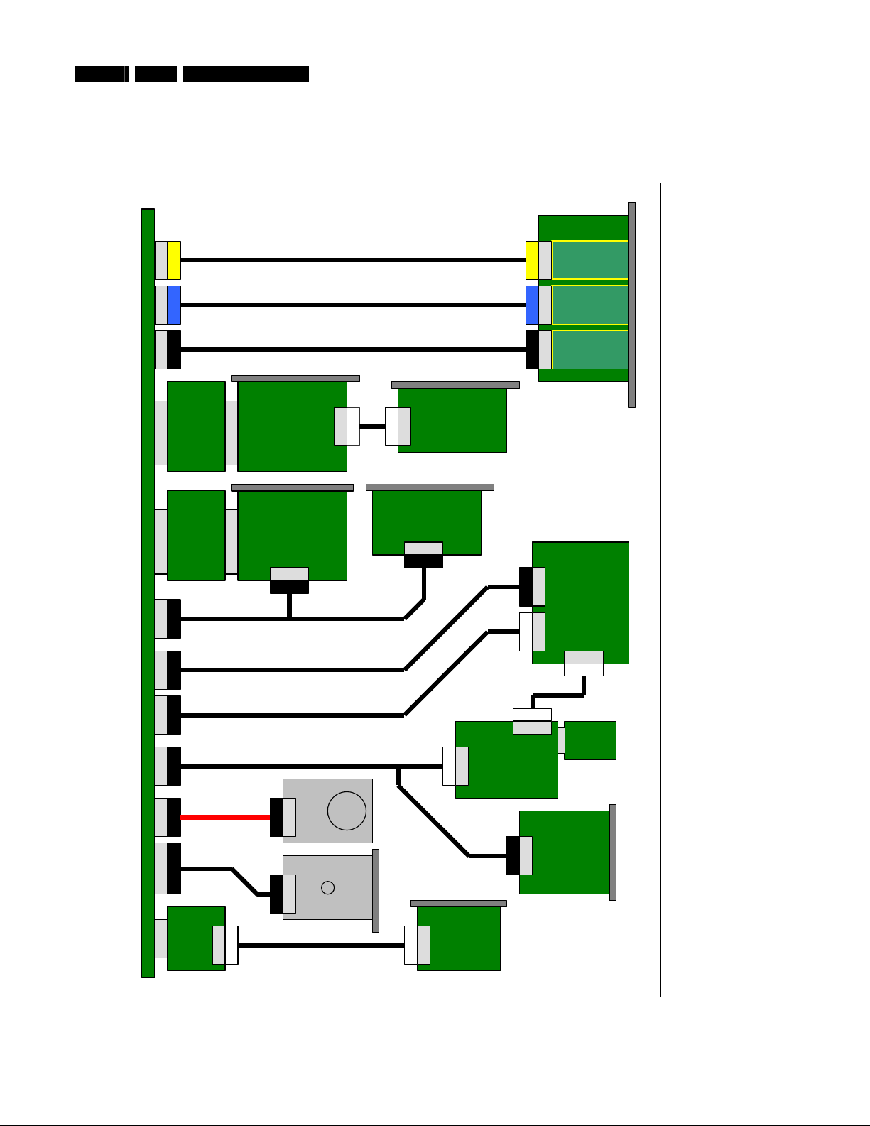
4.2. System Cable Definition
4.2.1. System Cable Schematic
J8H1
Cable 1
Technical Reference
FP I/O Board
JAUDIO1
FP_AUDIO
Front panel
J5A2 J8A2
PCI Riser TV Tuner Card
PCI Bus
PCI-E Riser Graphics Card
PCI-E Bus
MOTHERBOARD
J9H1 J6A1 J9C2 J7A2 SATA EIDE
Cable 2
Cable 3
Rear panel
PCI Bus
PCI-E Bus
Cable 11
Cable 4
Cable 5
Cable 7
JFP1 JJFP2
FP_1394
FP_USB
Rear panel
Cable 12
V2
-
TV Daughter Card
-
Rear panel Rear panel
SCART Daughter Card
-
SW Board
JFP1
VFD Board
JUSB1 J2
Cable 6
JRF2
JRF1
RF Board
HDD
MD Card
MDC
Cable 8
Cable 9
-
SATA
ODD
EIDE
Cable 10
Front panel
Card Reader
-
Rear panel
MD RJ-11 Board
-
Front panel
Figure 4.2-1
Page 7

4.2.2. System Cable Definition Table
Cable
Number
Cable Name Start End(s)
1 FP_AUDIO_CABLE MB J8H1 FP BOARD JAUDIO1
2 FP_1394_CABLE MB J5A2 FP BOARD JFP1
3 FP_USB_CABLE MB J8A2 FP BOARD JFP2
4 VFD_USB_CABLE MB J6A1 VFD Board JUSB1
5 IR_BLASTER_INTERNAL_CABLE MB J9C2 VFD BOARD J2
6 SW_RF_CABLE VFD Board JRF1 SW BOARD JRF2
Technical Reference
MCP9350i 4. EN 7
7 V-TYPE_CABLE MB J7A2 (1) SW BOARD JFP1
8 SATA_HDD_CABLE MB J7F1 HDD
9 ATA33_ODD_CABLE MB EIDE ODD
10 MD_CABLE MB MD CARD MD RJ-11 CONNECTOR BOARD
11 ADD2_SCART_CABLE MB J9H1 (1) ADD2 SCART DAUGHTER CARD
12 A/V_1x10_CABLE TV tuner AV2 TV daughter card
(2) CARD READER
(2) GRAPHICS CARD (ADD2 BOARD)
Page 8
p
p
EN 8 4. MCP9350i
Technical Reference
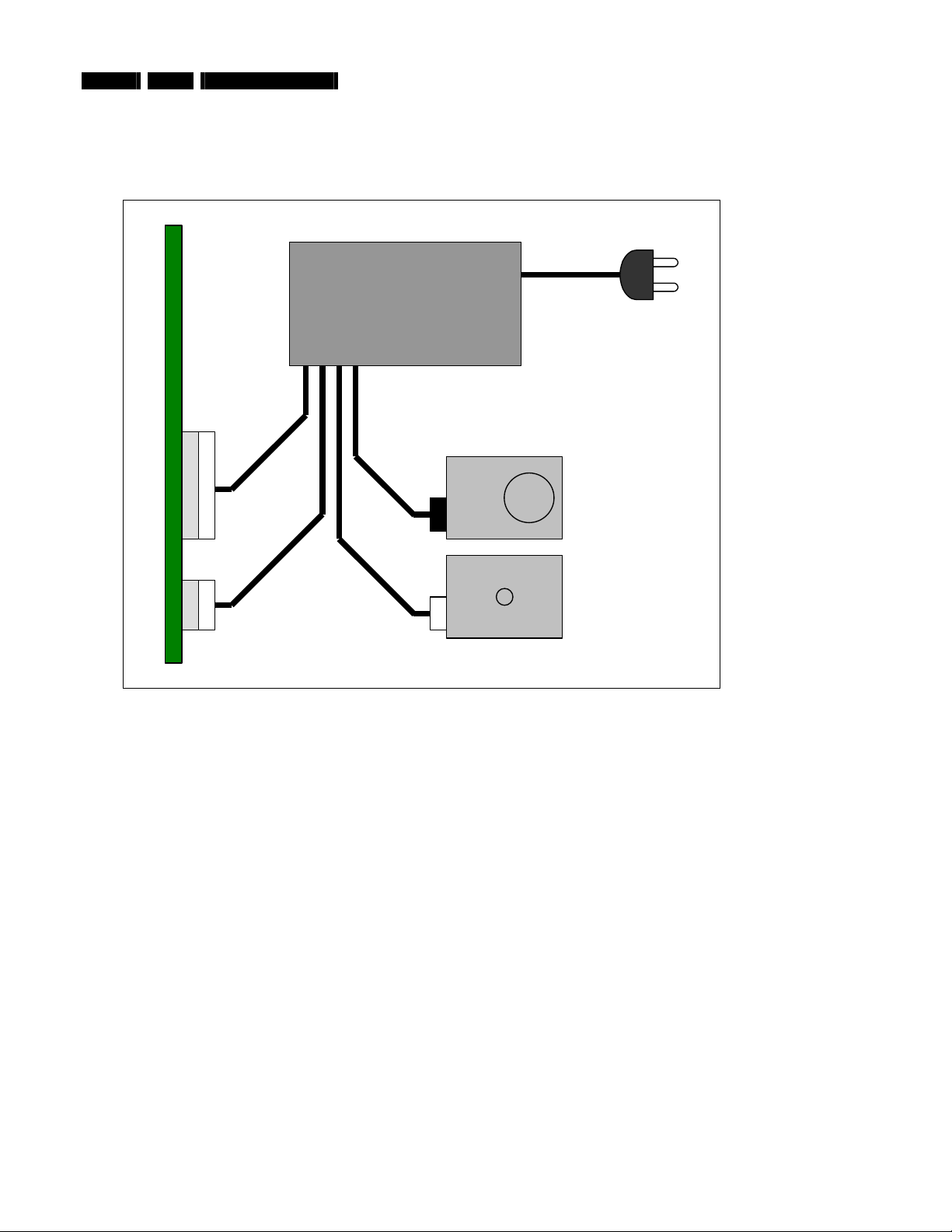
4.3. PSU Cables and Connectors Definition
4.3.1. PSU Cable Schematic
PSU
MOTHERBOARD
2x12-
in Main 2x2-
~
100-240 VAC
50/60 Hz
HDD
ODD
in
4-pinSATA
Figure 4.3-1
Page 9

4.3.2. PSU Connector Pin Definit i on
Technical Reference
MCP9350i 4. EN 9
Main Power Connector, 2x12-pin
Figure 4.3-2
Peripheral Power Connector, 4-pin
Figure 4.3-4
+12V Power Connector, 2x2-pin
Serial ATA (SATA) Power Connector
Figure 4.3-3
Figure 4.3-5
Page 10

EN 10 5. MCP9350i
Required Equipment List
5. Required Equipment List
Equipment & Facilities
• Repair kit
- Working samples of all modules of the MCP9350i
- Wireless keyboard with integrated trackball
- Remote control (MediaCenter version)
• PC Monitor with VGA and DVI input
• TV with SCART and S-Video input
• USB keyboard
• Stereo Headphones (with 6.3 mm Jack Plug)
•
Microphone (with 6.3 mm Jack Plug)
• IEEE 1394 4-pin device (example: digital video camcorder)
• IEEE 1394 6-pin device (example: external hard disk)
• USB device (examples: USB memory stick; USB mouse)
• External audio amplifier with the following connections:
- audio L/R cinch inputs (x2)
- coaxial SPDIF input
- optical SPDIF input
• Wireless (IEEE 802.11 b/g) access point and router with Ethernet LAN ports
• S-video signal source (examples: DVD player; video camcorder)
• Composite video signal source (examples: DVD player; video camcorder)
•
RF TV signal source (examples: external TV antenna; cable TV connection; VCR)
• RF Radio signal source (examples: external radio antenna; cable connection)
• Analogue telephone line
Cables
•
VGA cable
• DVI cable
• SCART cable
• S-Video cabl e
• IEEE 1394 4-pin cable
•
IEEE 1394 6-pin cable
• 2x Audio L/R Chinch cables
• Digital audio coax cable
• Digital audio optical cable
• Ethernet cable (RJ45, CAT5)
•
Telephone cable (RJ11)
• TV and Radio RF coax cable
Software Tools
• Recovery DVD
•
PC Doctor – Service Edition (CD and USB license)
• Test CD with latest BIOS, drivers, applications and PC Doctor test scripts
Memory Cards / Media
• Compact Flash (CF)
• Smart Media (SM)
• Secure Digital (SD)
• MultiMedia Card (MMC)
• Memory stick (MS)
• Audio CD
• Video DVD
• CD R / RW
• DVD+R / RW
Page 11
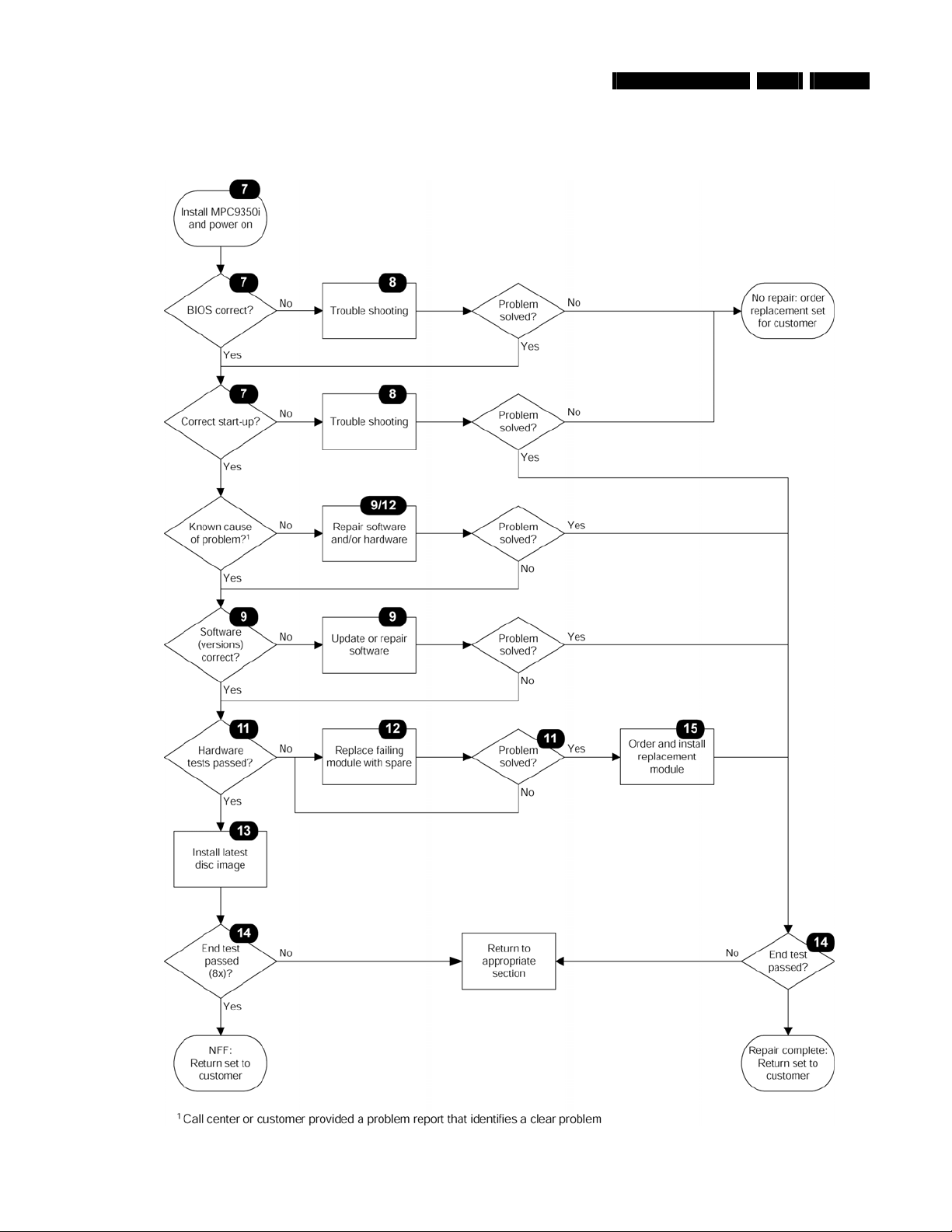
Diagnosis and Repair Flowchart
6. Diagnosis and Repair Flowchart
MCP9350i 6. EN 11
Figure 6-1
Page 12
EN 12 7. MCP9350i
Installation and Initial Checks
7. Installation and Initial Checks
7.1. Installation
1. Connect the MCP9350i to a monitor, using either the DVI or the VGA connector.
2. Insert the power cord (both 110V or 230V are supported). The LED on the Standby-On button should light-up yellow.
3. Connect a USB keyboard to one of the front USB ports.
7.2. BIOS Check
7.2.1. Test Procedure
Install the MCP9350i. See paragraph 7.1.
1.
2. Press the Standby-On button. The LED on the Standby-On button will turn-off and the MCP9350i should begin to start up.
3. During the early part of the start-up process press the ‘F2’ key on the keyboard to enter the BIOS setup.
4. On the BIOS setup main screen check the installed memory size. See table below.
Total memory size 512 MB
5. Check the system manufacturer information. (BIOS menu select: Main > Additional system information). See table below.
System information > manufacturer “Tatung co.”
Desktop board information > manufacturer Intel Corporation
Chassis Information > Manufacturer Philips MCPC1001
6. Check the BIOS version. (BIOS menu select: Main > BIOS version). See table below.
Software module Release version
System BIOS SU94510J.86A.0048
7. Check that the HDD and the optical drive have been detected by the BIOS. (BIOS menu select: Advanced > Drive
Configuration
Drive Type
HDD (primary supplier) Western Digital WD????JS-55M-250.0GB
Optical Drive Philips DVDR1628 – ATAPI
8. Check the function of the temperature sensors. Confirm that the temperatures have reasonable values, between 0 C and 128 C.
(BIOS menu select:
Temperature Sensor Possible value (allow for a wide variation)
Processor 1 63 C
Front internal 31 C
Rear internal 25 C
Remote 1 23 C
Remote 2 21 C
Check the fan speeds. (BIOS menu select:
9.
Fan Speed (allow for a wide variation)
Processor 1 fan 900 – 1400 RPM
Rear fan 1000 RPM
). See table below.
Advanced > Hardware Monitoring). See table below.
Advanced
>
Hardware Monitoring
). See table below.
Page 13

10. Check the power values. (BIOS menu select: Advanced > Hardware Monitoring). See table below.
Power Center value (allow for a ± 5% variation)
V 12.0 +12.0 V (± 0.6 V)
V 5.0 +5.0 V (± 0.25 V)
V 3.3 + 3.3 V (± 0.165 V)
V 1.5 +1.5 V (± 0.075 V)
V ccp + 1.28 V (± 0.064 V)
11. Exit the BIOS setup screen without saving changes. (BIOS menu select: Exit > Exit discarding chan ges ).
The MCP9350i will now continue to start-up. Perform the start-up sequence check, see paragraph 7.3.
7.2.2. Fail Procedure
Perform Troubleshooting procedure. See paragraph 8.
Installation and Initial Checks
MCP9350i 7. EN 13
Page 14
EN 14 7. MCP9350i
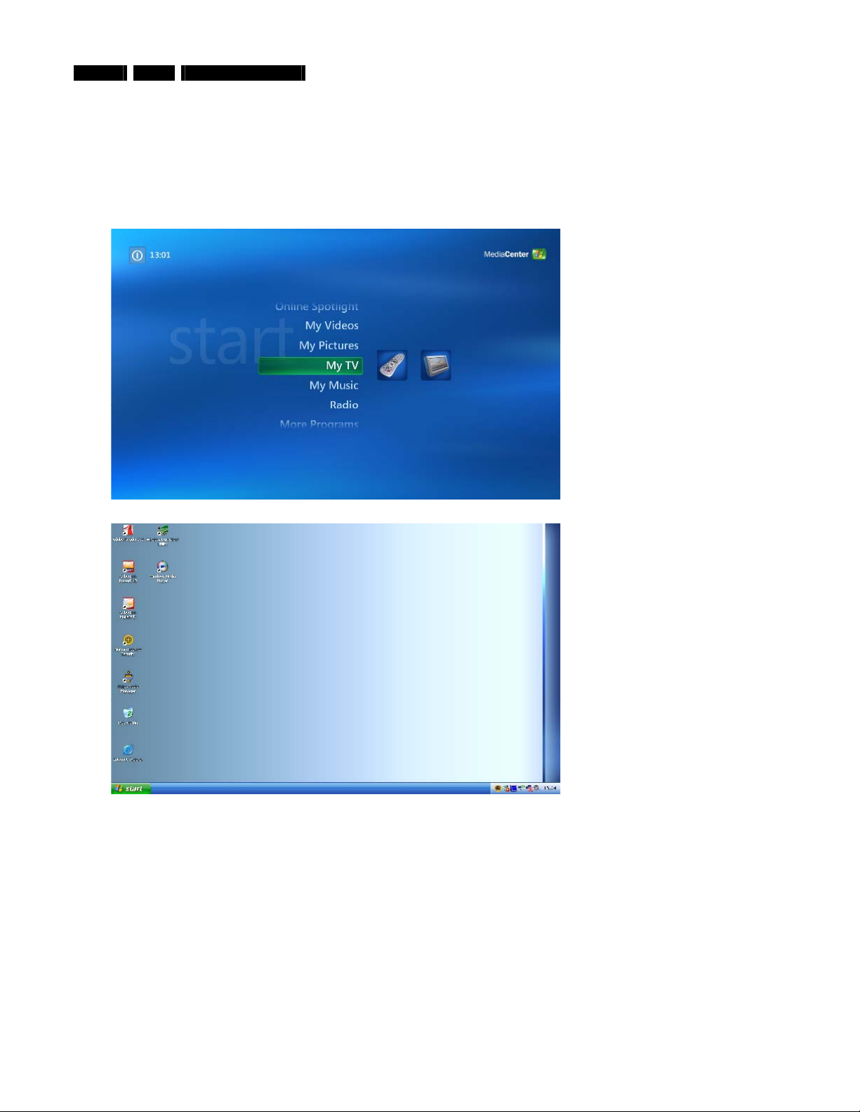
7.3. Start-up Sequence Check
7.3.1. Test Procedure
1.
Power on the MCP9350i.
2. Watch the boot-up sequence for error messages.
3. After a short time the Windows Media Center main window, or the Windows XP desktop (possibly adapted by the user), will be
shown on-screen.
Installation and Initial Checks
7.3.2. Fail Procedure
Perform Troubleshooting procedure. See paragraph 8.
Figure 7.3-1: Media Center main window (English version)
Figure 7.3-2: Windows XP desktop (English version)
Page 15

Troubleshooting - Start-up Failure
8. Troubleshooting - Start-up Failure
8.1. Problems in BIOS
This section lists potential BIOS problems together with recommended corrective actions.
•
Incorrect BIOS version
- Update the BIOS. See paragraph 9.2.
• Drive(s) not detected
- Replace the drive cabl e(s).
- Replace the drive(s). See paragraph 12.3 or 12.4.
Note: Any service to non-standard drives must be treated as an out-of-warranty service call.
• Incorrect temperature
- Check that the thermistor plugs on the motherboard are correctly inserted. See paragraph 12.16.9.
- Replace the motherboard. See paragraph 12.16.9.
• Incorrect fan speeds (with correct temperature)
- Re-insert fan cables.
- Replace fan. See paragraph 12.15.5.
- Replace motherboard. See paragraph 12.16.9.
• Incorrect power
- See paragraph 8.2.
• No or insufficient memory (512 MB expected)
- Re-insert the memory modules. See paragraph 12.16.7.
- Remove the memory modules and insert in the other connector bank (black DIMM connectors on the motherboard).
- Replace the memory modules. See paragraph 12.16.7.
- Replace the motherboard. See paragraph 12.16.9.
•
Chassis manufacturer is not ‘
- Update the BIOS. See paragraph 9.2.
Philips MCPC1001’
MCP9350i 8. EN 15
8.2. No or Incorrect Power
1. Re-insert the PSU cables.
2. Disconnect the PSU cables and measure the voltages. See paragraph 4.3.2.
- If the values are incorrect replace the PSU. See paragraph 12.14.1.
3. Replace the SW Board. See paragraph 12.10.
4. Reinsert CPU or replace the CPU. See paragraph 12.16.5.
5. Replace the motherboard. See paragraph 12.16.9.
8.3. No Video
1. Make sure that a working monitor is connected and in the correct mode (VGA or DVI).
2. Remove the memory from the motherboard, (see paragraph 12.16.7), and reboot. If there is a beeping sound, replace the memory.
3. Re-insert the memory. See paragraph 12.16.7.
If there is still no video, replace the graphics card. See paragraph 12.6.
4.
Replace the motherboard. See paragraph 12.16.9.
5.
8.4. Operating System Not Found
Reboot the MCP9350i and enter the BIOS menu by pressing ‘F2’. Confirm that the HDD is detected.
1.
2. Replace the SATA cable.
3. Replace the HDD. See paragraph 12.3.
4. Re-insert the memory modules. See paragraph 12.16.7.
5. Remove the memory modules and insert in the other connector bank (black DIMM connectors on the motherboard).
6. Replace the memory modules. See paragraph 12.16.7.
7. Replace the motherboard. See paragraph 12.16.9.
8.5. No Repair
If none of the above recommendations have solved the problem and the set cannot be repaired, it must be sent for further analysis to
Philips. If the incident happened within the warranty period, the customer shall be provided with a new set. Please initiate a ‘non-policy
replacement’ procedure with Euroservice.
Page 16

EN 16 9. MCP9350i
Software Update and Repair
9. Software Update and Repair
This section describes how to update and ‘repair’ the software on the MCP9350i without affecting the customer’s data.
9.1. Software Update and Repair Flowchart
Page 17
9.2. Update BIOS
Update the BIOS after installing a new motherboard, or when the MCP9350i is programmed with an older version of the BIOS.
1. Insert the bootable disc with the latest BIOS version.
2. Restart the MCP9350i.
3. Follow the on-screen instructions.
9.3. Updat e Drivers and Software
The table below lists the drivers and software applications that are installed on the MPC9350i and that could theoretically have been
altered by the customer in such a way that the system stopped performing correctly.
Software module Release version
Microsoft MediaCenter Edition MCE Version 2005 SP2, v.2161
Intel chipset software installation utility 7.0.0.1025
Intel 945G Graphics PV14.17.1.4399 (ver. 6.14.10.4399)
Intel 82562EZ or 82562EX (10/100) LAN controller 8.0.19.0
Sigmatel Audio Drivers v012_4641_EPC_W
C-com / Smartlink Azalia modem 7.23.00.00
Lite-On Atheros WLAN 4.1.2.57
Tatung Front Panel Manager
VFD w/ button board
Tatung VFD Firmware 1.10_PV
ODD FW P1.0
Nvidia (TV Tuner) Nvidia_5.9.4.86
LikeMusic Like Music GM
CyberLink AP (Power DVD, Make DVD, Capture DV) Cyberlink GM 3.0
Philips Media Manager Program PMM_windows_3_2_1_0004
In case of a problem with the software, the normal procedure is to recover the system with the latest disc image (as provided by Philips).
Repair or upgrade of the software is on the repair technician’s own risk.
Software Update and Repair
1.1_PV
MCP9350i 9. EN 17
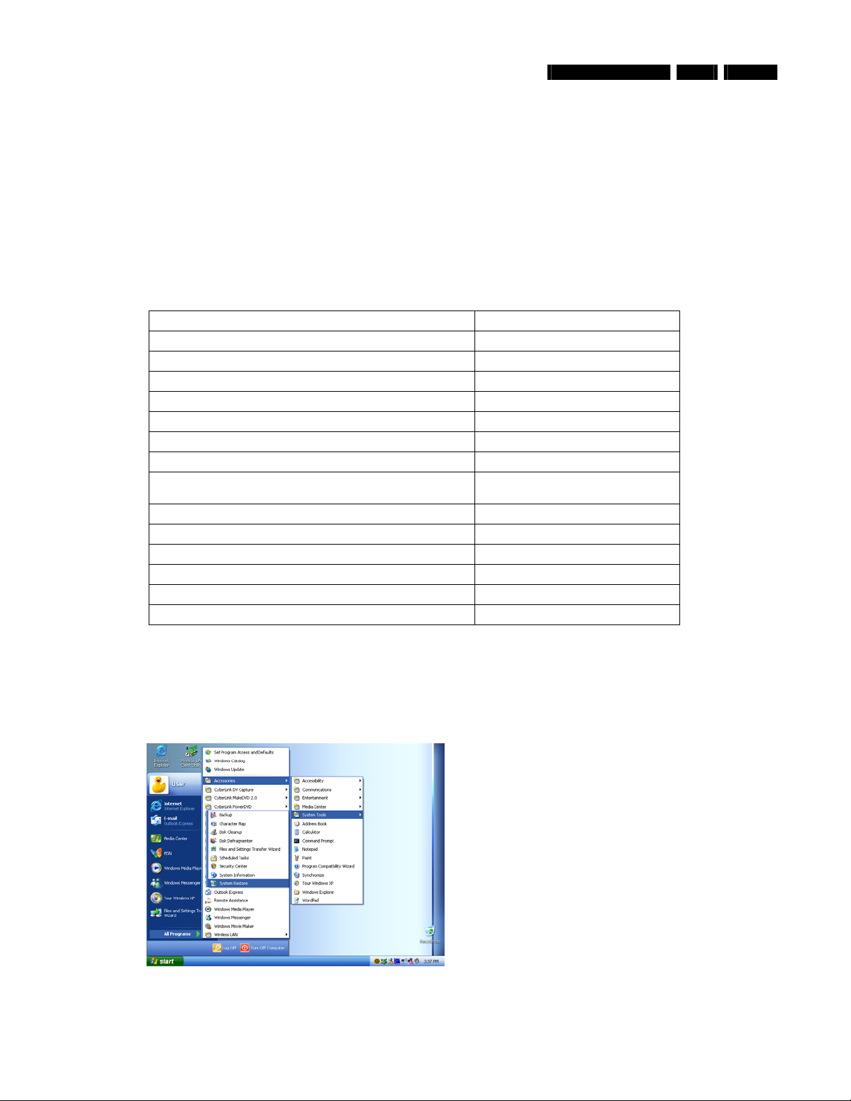
9.4. System Restore
1. In Windows XP select: Start > All programs > Accessories > System Tools > System Restore.
Figure 9.4-1
Page 18

EN 18 9. MCP9350i
2. Select the ‘restore my system to an earlier time’ option.
Software Update and Repair
3. Select a date in time before the problems were first seen.
4. Carefully read the instruction and continue.
Figure 9.4-2
Figure 9.4-3
Figure 9.4-4
Page 19

9.5. System Recovery
A system restore is used to return the set to its original software configuration. If a later software built is available, this built should be
installed on the system instead (see Chapter 13 – Software Re-installation)
1. In Windows XP select: Start > All programs > System Recovery > System Recovery. (Alternatively, press the F11 key during
boot sequence).
Software Update and Repair
MCP9350i 9. EN 19
2. Follow the on-screen instructions to perform a system recovery without performing a format, (operations from this point are carried
out in DOS mode).
Figure 9.5-1
Figure 9.5-2
Page 20

EN 20 10. MCP9350i
PC Doctor Diagnostic Tool
10. PC Doctor Diagnostic Tool
10.1. PC Doctor Introduction
PC Doctor is a software based test tool that is used to verify the correct functioning of different modules.
10.2. Running PC Doctor
1. Insert the ‘PC Doctor’ USB dongle in one of the USB slots on the back of the MCP9350i.
2. Insert the PC Doctor disc.
3. If this is the first time that the dongle is used, install the driver for the USB dongle from the PC Doctor disc.
4. Start PC Doctor in the ‘Quick Install and Run’ mode (otherwise certain tests will not be enabled). See Figure 10.2-1.
5. PC Doctor will now run. Select the ‘diagnostics’ option. You are now ready to run one of the tests by selecting one of the icons.
See Figure 10.2-2.
Note: It is recommended that test sequences be run using the PC Doctor batc h files provided by Phil ips. See paragraph 10.3.
Note: More information on the type and sequence of tests can be found in paragraph 11.2.
Figure 10.2-1
Figure 10.2-2
Page 21

10.3. PC Doctor Batch Tests
Sequences of PC Doctor tests can be pre-programmed to run in batches. There are two pre-programmed test batch files provided by
Philips on the Test CD. These are identified as ‘Automatic’ tests and ‘Interactive’ tests.
Automatic tests
These are tests that run fully automatic, without any user interaction. This test sequence takes approximately 15 minutes to complete.
1. Copy the test script ‘Automatic.PCB’ from the test CD to the HDD of the MCP9350i.
2. Insert a DVD+RW disc in the optical drive.
Insert memory cards in all four slots of the memory card reader.
3.
Connect the set with the network using an Ethernet cable.
4.
Insert the telephone line in the modem connector.
5.
6. Insert the USB flash drive containing the batch files.
7. In the PC Doctor menu select: Test Set > Custom Test Settings.
8. Open the automated test batch file ‘Automatic.PCB’ from the HDD and start the test sequence.
9. Remove the test script from the HDD after the test sequence has finished.
Interactive tests
These tests require some action of the user (listening to sound, pushing buttons at the keyboard, etc.). This test sequence takes
approximately 5 minutes to complete.
1. Copy the test script ‘Interactive.PCB’ from the test CD to the HDD of the MCP9350i.
Insert the USB flash drive containing the batch files.
2.
In the PC Doctor menu select:
3.
Open the interactive test batch file ‘
4.
5. Follow the on-screen instructions.
6. Remove the test script from the HDD after the test sequence has finished.
>
Test Set
Interactive.PCB
PC Doctor Diagnostic Tool
Custom Test Settings
’ from the HDD and start the test sequence.
.
MCP9350i 10. EN 21
Page 22

EN 22 11. MCP9350i
11. Hardware Tests
11.1. Introduction
The purpose of the hardware tests is to guarantee the correct functioning of all hardware modules. There are three cases:
1. The cause of the hardware problem is known. Run the appropriate test to confirm that the cause of the problem is correct. Swap
the failing module with one from the ‘repair kit’. Run the test again. For swapping: swap the cheapest component first (e.g. cables,
riser boards), then the modules and finally the motherboard.
2. The cause of the problem is not known. Start with the first test (see below) and continue until one of the tests fails. Then swap the
failing module, etc.
3. None of the tests identifies a failing module. If the technician suspects that the problem is not covered by the tests, he can create
his own test. Otherwise, the product is marked as ‘NFF’. When the new test finds a problem, the technician has to inform Philips
about this so it can be used to improve the test process.
Hardware Tests
Page 23

11.2. Test Sequence
# Test Method
(paragraph)
1 7.2 BIOS check Manual
2 7.3 Start-Up sequence Manual
3 11.3 Fan speed Manual
4 11.4 CPU Automatic
5 11.5 HDD (Hard disk drive) Automatic
6 11.6 Memory card reader Automatic
7 11.7 ODD (Optica l disk drive) Automatic
8 11.8 Memory Automatic
9 11.9 PCI cards Automatic
10 11.10 Ethernet connection Automatic
11 11.11 Modem Automatic
12 11.12 Graphics card Automatic
13 11.13 USB controllers Automatic
14 11.14 CMOS Automatic
15 11.15 Motherboard Automatic
16 11.16 IEEE 1394 controller Automatic
17 11.17 Rear Panel Audio Output Connectors Interactive
18 11.18 Wireless keyboard (and receiver) Interactive
19 11.19 Microphone, headphones and headphones volume control Interactive
20 11.20 Wireless network connection Manual
21 11.21 USB connectors Manual
22 11.22 IEEE 1394 connectors Manual
23 11.23 Video outputs Manual
24 11.24 FM Tuner Manual
25 11.25 TV Tuner Card and Audio / Video Inputs Manual
26 11.26 Front display and buttons Manual
27 11.27 Remote control and infrared receiver Manual
28 11.28 IR blaster Manual
Hardware Tests
Module Test Type ; Checked
MCP9350i 11. EN 23
Page 24

EN 24 11. MCP9350i
11.3. System Fans
11.3.1. Required Equipment
None.
11.3.2. Test Procedure
At first start-up, the PSU and CPU fans will start at the highest speed. After a couple of seconds, the fans must switch to a slower speed.
Note: When the system has already been running, the fans might start at the lower speed.
11.3.3. Fail Procedure
- Replace the PSU fan. See paragraph 12.14.3.
- Replace the CPU fan. See paragraph 12.15.5.
- Replace the motherboard. See paragraph 12.16.9.
11.4. CPU
11.4.1. Required Equipment
PC Doctor CD & USB dongle
11.4.2. Test Procedure
In PC Doctor: Run the CPU test.
Hardware Tests
11.4.3. Fail Procedure
Replace the CPU. See paragraph 12.16.5.
11.5. HDD (Hard disk drive)
11.5.1. Required Equipment
PC Doctor CD & USB dongle
11.5.2. Test Procedure
In PC Doctor: Run the ‘SMART’ test.
11.5.3. Fail Procedure
- Replace the SATA cable.
- Replace the HDD. See paragraph 12.3.
- Make sure that the latest software image is installed on the replacement HDD. See paragraph 13.
11.6. Card Reader
11.6.1. Required Equipment
• PC Doctor CD & USB dongle
• Compact Flash (CF) card
• Smart Media (SM) card
• Secure Digital (SD) card
• Memory Stick (MS)
11.6.2. Test Procedure
Insert the memory cards into the appropriate slots of the card reader.
1.
In PC Doctor: Run the card reader test.
2.
11.6.3. Fail Procedure
- Replace the V-Type cable.
- Replace the card reader board. See paragraph 12.11.3.
- Replace the motherboard. See paragraph 12.16.9.
Page 25

11.7. ODD
11.7.1. Required Equipment
•
PC Doctor CD & USB dongl e
• DVD+RW disc
11.7.2. Test Procedure
Insert the DVD+RW disc into the ODD.
1.
2. In PC Doctor: Run the DVD+RW test.
11.7.3. Fail Procedure
- Replace the ATA33 cable.
- Replace the ODD. See paragraph 12.4.
11.8. Memory
11.8.1. Required Equipment
PC Doctor CD & USB dongle
11.8.2. Test Procedure
In PC Doctor: Run the memory test.
Hardware Tests
MCP9350i 11. EN 25
11.8.3. Fail Procedure
- Remove the memory modules and insert in the other connector bank (black DIMM connectors on the motherboard).
- Replace the defective DIMM. See paragraph 12.16.7.
11.9. PCI Cards
11.9.1. Required Equipment
PC Doctor CD & USB dongle
11.9.2. Test Procedure
In PC Doctor: Run the PCI test.
11.9.3. Fail Procedure
- Replace the Riser Card associated with the failing PCI card. See paragraph 12.6 or 12.7.
- Replace the failing PCI card. See paragraph 12.6 or 12.7.
11.10. Ethernet
11.10.1. Required Equipment
•
PC Doctor CD & USB dongl e
• Wireless router/access point with Ethernet ports
• Ethernet cable
11.10.2. Test Procedure
Connect the Media Centre PC with the router using the Ethernet cable.
1.
2. In PC Doctor: Run the network test.
11.10.3. Fail Procedure
Replace the motherboard. See paragraph 12.16.9.
Page 26

EN 26 11. MCP9350i
11.11. Modem
11.11.1. Required Equipment
•
PC Doctor CD & USB dongle
• Active telephone line
• Telephone cable
11.11.2. Test Procedure
Connect the Media Center PC to the telephone line using the telephone cable.
1.
In PC Doctor: Run the modem test.
2.
11.11.3. Fail Procedure
- Replace the modem cable.
- Replace the RJ11 connector board. See paragraph 12.9.5.
- Replace the modem board. See paragraph 12.9.1.
- Replace the motherboard. See paragraph 12.16.9.
11.12. Graphics Card
11.12.1. Required Equipment
PC Doctor CD & USB dongle
Hardware Tests
11.12.2. Test Procedure
In PC Doctor: Run the 2d/3d test
11.12.3. Fail Procedure
- Replace PCI-express riser board. See paragraph 12. 6.
- Replace graphics card. See paragraph 12.6.
11.13. USB Controllers
11.13.1. Required Equipment
PC Doctor CD & USB dongle
11.13.2. Test Procedure
In PC Doctor: Run the USB test
11.13.3. Fail Procedure
Replace the motherboard. See paragraph 12.16.9.
11.14. CMOS
11.14.1. Required Equipment
PC Doctor CD & USB dongle
11.14.2. Test Procedure
In PC Doctor: Run the CMOS test
11.14.3. Fail Procedure
Replace the motherboard. See paragraph 12.16.9.
Page 27

11.15. Motherboard
11.15.1. Required Equipment
PC Doctor CD & USB dongle
11.15.2. Test Procedure
In PC Doctor: Run the system board test
11.15.3. Fail Procedure
Replace the motherboard. See paragraph 12.16.9.
11.16. IEEE 1394 Controller
11.16.1. Required Equipment
PC Doctor CD & USB dongle
11.16.2. Test Procedure
In PC Doctor: Run the IEEE 1394 test
11.16.3. Fail Procedure
Replace the motherboard. See paragraph 12.16.9.
Hardware Tests
MCP9350i 11. EN 27
11.17. Rear Panel Audio Output Connectors
11.17.1. Required Equipment
• An external amplifier that has:
• 2 analogue audio inputs
• a coaxial SPDIF input
• an optical SPDIF input
•
Cables for each of these four inputs
11.17.2. Test Procedure
Connect the four audio outputs of the Media Center with the amplifier.
1.
2. In PC Doctor: Run the Sound test.
Select the first input on the amplifier and push some on-screen test buttons to get sound on the different boxes.
3.
Repeat this for the other three inputs on the amplifier.
4.
11.17.3. Fail Procedure
Replace the motherboard. See paragraph 12.16.9.
11.18. Wireless Keyboard and Receiver
11.18.1. Required Equipment
• PC Doctor CD & USB dongle
• The wireless keyboard that was returned with the set.
• If no keyboard was returned, use your own wireless keyboard.
11.18.2. Test Procedure
In PC Doctor: Run the keyboard test and follow the instructions, (if using the keyboard from the customer make sure to push all keys).
11.18.3. Fail Procedure
- Re-connect the keyboard with the set. (Press the ‘connect’ button on the Media Center front panel and then press the connect
button on the keyboard).
- Replace the keyboard batteries.
- Replace keyboard.
- Replace the RF board. See paragraph 12.10.
- Replace the motherboard. See paragraph 12.16.9.
Page 28

EN 28 11. MCP9350i
Hardware Tests
11.19. Microphone, Headphones and Headphones Volume Control
11.19.1. Required Equipment
•
PC Doctor CD & USB dongle
• Headset (combined headphones/microphone) with two 9mm jack plugs
11.19.2. Test Procedure
In PC Doctor: Run the microphone test and follow the instructions.
1.
2. Play the recorded sound a number of times, using the volume buttons to increase and decrease the volume.
11.19.3. Fail Procedure
- Replace the FP Audio cable.
- Replace the FP I/O board. See paragraph 12.12.3.
- Replace the motherboard. See paragraph 12.16.9.
Page 29

11.20. Wireless Network Connection (802.11b/g)
11.20.1. Required Equipment
Wireless router/access point within range of the Media Center PC
11.20.2. Test Procedure
In Windows XP, open the Wireless LAN client utility. (Select: Start > All Programs > Wireless LAN).
1.
2. Set-up a connection with the wireless access point: in the Site Survey section select Refresh and Connect with the access point.
Make sure that you enter the correct protection key if necessary.
Hardware Tests
MCP9350i 11. EN 29
Select the Status section. Both link quality and signal strength should now be sufficiently high. (Maximum values are 52.0 Mbps and
3.
100%).
11.20.3. Fail Procedure
- Replace both antenna cables and antennas. See paragraphs 12.8.3 and 12.8.5.
- Replace the WLAN card. See paragraph 12.8.1.
- Replace the motherboard. See paragraph 12.16.9.
Page 30

EN 30 11. MCP9350i
11.21. USB Connectors
11.21.1. Required Equipment
USB memory stick or USB mouse
11.21.2. Test Procedure
Insert the USB device into one of the USB slots.
1.
2. Check that the device is detected and that it functions correctly.
3. Repeat this procedure for each of the four USB slots (2 on the front, 2 at the rear).
11.21.3. Fail Procedure
For the front USB connectors:
- Replace the FP_USB cable.
- Replace the FP I/O board. See paragraph 12.12.3.
- Replace the motherboard. See paragraph 12.16.9.
For the rear USB connectors:
- Replace the motherboard. See paragraph 12.16.9.
11.22. IEEE 1394 Connectors
11.22.1. Required Equipment
• 1394 device (e.g. external hard disc or a digital camera)
•
4-pin and 6-pin 1394 cables
Hardware Tests
11.22.2. Test Procedure
Insert the 1394 device into one of the 1394 slots.
1.
2. Check that the device is detected and that it functions correctly.
3. Repeat this procedure for each of the three 1394 slots (1 on the front, 2 at the rear).
11.22.3. Fail Procedure
For the front 1394 connector:
- Replace the 1394 cable.
- Replace the FP I/O board. See paragraph 12.12.3.
- Replace the motherboard. See paragraph 12.16.9.
For the rear 1394 connectors:
- Replace the motherboard. See paragraph 12.16.9.
Page 31

11.23. Graphics Card and Video Output Connectors
11.23.1. Required Equipment
•
TV and/or Monitor with the following inputs:
• SCART
• DVI
• VGA
• S-Video
•
Cables for each of these inputs
11.23.2. Test Procedure
Connect the TV and/or monitor to the four video outputs of the Media Center.
1.
2. On the MediaCenter: select the ‘Intel® Graphics Media Accelerator Driver’ icon in the icon bar on the bottom right.
3. Select the graphics properties option.
4. Select the ‘Intel® Dual Display Clone’ option and make sure that the primary device is ‘digital display’ and the secondary device
is ‘
television
’.
Hardware Tests
MCP9350i 11. EN 31
5. Switch you monitor and/or TV between the different inputs to check if the desktop can be seen on all four (Scart, DVI, VGA and S-
Video) output modes.
6. Return the set to the original settings.
11.23.3. Fail Procedure
For the SCART output:
- Replace the ADD2_SCART cable.
- Replace SCART connector board. See paragraph 12.16.3.
- Replace PCI-express riser board. See paragraph 12. 6.
- Replace graphics card. See paragraph 12.6.
- Replace the motherboard. See paragraph 12.16.9.
For the DVI, VGA or S-Video outputs:
- Replace PCI-express riser board. See paragraph 12. 6.
- Replace graphics card. See paragraph 12.6.
- Replace the motherboard. See paragraph 12.16.9.
Page 32

EN 32 11. MCP9350i
11.24. FM Tuner
11.24.1. Required Equipment
RF FM Radio signal source (examples: external FM antenna, cabl e)
11.24.2. Test Procedure
In MediaCenter, select the
Radio
Hardware Tests
option and search for a channel.
11.24.3. Fail Procedure
- Replace the PCI riser card. See paragraph 12.7.1.
- Replace the TV tuner card. See paragraph 12.7.1.
- Replace the motherboard. See paragraph 12.16.9.
Page 33

11.25. TV Tuner Card and Audio/Video Inputs
11.25.1. Required Equipment
•
RF TV signal source (examples: external TV antenna, cable TV, VCR)
• Composite Video signal source (examples: DVD player, camcorder)
• S-Video signal source (examples: DVD player, camcorder)
11.25.2. Test Procedure
Connect the Composite Video source to the upper connector on the MCP9350i back panel.
1.
Connect the TV signal source to the TV RF-in connector.
2.
Go to the TV signal setup section in the Windows Media Center program. (Select:
3.
Hardware Tests
MCP9350i 11. EN 33
> TV >
Settings
Set Up TV Signal
)
4. Acknowledge that the current settings will be deleted (in actuality, the procedure will be cancelled at the end so the settings will
remain).
5. Select the correct region.
Page 34

EN 34 11. MCP9350i
6. Select the manual configuration option (this screen is skipped in some versions).
7. Select Cable or Digital Cable as the source of the TV signal.
Hardware Tests
Select the correct signal type (in general: NTSC for America, PAL/SECAM for Europe).
8.
Page 35

9. Indicate that you want to install a set top box.
10. The Which Tuners Do You Want to Confiure? screen will appear. Select NVIDIA NVTV Dual Tuner Card Tuner 1 (the upper
Composite and S-Video connectors).
Hardware Tests
MCP9350i 11. EN 35
11. Select Enter Channel and enter a channel number that should be available. Check if you can see the expected TV signal in the
small video window on the right.
12. Select Composite Video. Check for the expected Composite Video signal in the video window.
Disconnect the Composite Video cables from the MCP9350i. Connect the S-Video source to the upper connector on the back
13.
panel.
Select
14.
15. Move the S-Video cable to the lower connector on the MCP9350i back panel.
. Check for the expected S-Video signal in the video window, if necessary click
S-Video
Scan again
to refresh the display.
Page 36

EN 36 11. MCP9350i
16. Click on back to return to the Which Tuners Do You Want to Confiure? screen. Select NVIDIA NVTV Dual Tuner Card Tuner 2.
17. Repeat the previous S-Video and Composite video checks for Tuner 2.
18. Click on ‘Cancel’ to stop this TV signal installation, without saving the new settings.
11.25.3. Fail Procedure
- Replace the PCI riser card. See paragraph 12.7.1.
- Replace the TV tuner card. See paragraph 12.7.1.
- Replace the motherboard. See paragraph 12.16.9.
Hardware Tests
11.26. VFD Di sp l a y an d Bu t t o n s
11.26.1. Required Equipment
Audio CD
11.26.2. Test Procedure
Insert an Audio CD into the ODD.
1.
Use the transport control buttons located below the VFD display to navigate the CD. Check that each button operates correctly.
2.
3. Check that the VFD display is functioning.
11.26.3. Fail Procedure
- Replace the VFD_USB cable.
- Replace the VFD board. See paragraph 12.13.
- Replace the motherboard. See paragraph 12.16.9.
11.27. Remote Control and Infrared Receiver
11.27.1. Required Equipment
•
Use the remote control that was returned with the Media Center.
• If no remote control was returned, use your own.
11.27.2. Test Procedure
Use the volume up and down buttons on the remote control to test correct operation of the infrared receiver and remote.
11.27.3. Fail Procedure
- Replace the remote control batteries.
- Replace the remote control.
- Replace the VFD_USB cable.
- Replace the VFD board. See paragraph 12.13.
- Replace the motherboard. See paragraph 12.16.9.
Page 37

11.28. IR Blaster
11.28.1. Required Equipment
• Two IR blaster cables
• Test CD
11.28.2. Test Procedure
1.
Insert the two IR blaster cables in the rear IR blaster ports.
2. Hold the 'eyes' of the cables in front of the IR receiver in the front of the set (to the left of the VFD display).
3. Open a command window. (Select: Start > Run. Type 'cmd' and click OK).
4. In the command window: find and run the program 'IR.bat'.
5. Check if both cables pass the test. If not, move the 'eyes' a bit and try again until absolutely sure that there is a hardware failure.
11.28.3. Fail Procedure
Replace the motherboard. See paragraph 12.16.9.
Hardware Tests
MCP9350i 11. EN 37
Page 38

EN 38 12. MCP9350i
12. Hardware Repair
This section provides instructions on how to remove and replace modules from the Media-Center.
12.1. Top Cover
12.1.1. Top Cover Removal
WARNING:
1. At the rear of the chassis remove the 4 torx screws (1). See Figure 12.1-1.
2. Slide the top cover towards the rear, until the locking tabs disengage. See Figure 12.1-2.
3. Lift the top cover straight up and remove it from the chassis.
4. Store the top cover in a safe place.
Disconnect the AC power from the MCP9350i before removing the top cover.
Hardware Repair
1
1
12.1.2. Top Cover Re-Assembly
To re-assemble the top cover, do all processes described in paragraph 12.1.1 in reverse order.
Note: The torque setting required for the top cover screws (1) is 8kg-cm
Note: Check the top cover for damage after re-assembly.
Figure 12.1-1
1
1
Figure 12.1-2
Page 39

12.2. Main Bezel
12.2.1. Main Bezel Removal
1.
Check the front of the MCP9350i for cosmetic damage. Make a note of any existing damage to the main bezel and ODD bezel.
2. Remove the top cover. See paragraph 12.1.1.
3. At the front of the MCP9350i insert a straightened paper clip into the access hole under the ODD tray.
4. Push the paper clip until the ODD tray (1) is unlocked. See Figure 12.2-1.
5. Carefully turn the MCP9350i over, so that the bottom side of the chassis is facing upwards.
6. Carefully pull the ODD tray out to gain access to the underside of the ODD bezel.
7. Release the 2 locking tabs (2), and remove the ODD bezel. See Figure 12.2-2.
8. Store the ODD bezel in a safe place.
9. Push the ODD tray in until it closes.
Turn the MCP9350i over, so that the topside of the chassis is facing upwards.
10.
Remove the 2 countersunk screws (3). See Figure 12.2-3.
11.
Release the main bezel upper locking tab (4). See Figure 12.2-3.
12.
13. Pull the top of the main bezel forwards and downwards until the lower locking tabs disengage. See Figure 12.2-4.
14. Remove the main bezel from the chassis.
15. Store the main bezel in a safe place. Avoid touching the inside of the display window.
Hardware Repair
MCP9350i 12. EN 39
1
Figure 12.2-1
3
4
3
2
Figure 12.2-2
2
12.2.2. Main Bezel Re-Assembly
To re-assemble the main bezel, do all processes described in paragraph 12.2.1 in reverse order.
Note: Clean the MCP9350i before re-assembly
The torque setting required for the main bezel screws (3) is 8kg-cm
Note:
Note: Check the main bezel and the ODD bezel for cosmetic damage after re-assembly. Replace only when additional damage has
been caused during the diagnosis and repair procedure.
Figure 12.2-3
Figure 12.2-4
Page 40

EN 40 12. MCP9350i
12.3. HDD (Hard Disk Drive)
12.3.1. HDD Subassem b ly Removal
1.
Remove the top cover. See paragraph 12.1.1.
2. Disconnect all cables ( 1) from the HDD. See Figure 12.3-1.
3. Remove the 2 mounting screws (2) from the HDD subassembly. See Figure 12.3-2.
4. Slide the HDD subassembly towards the left, until the locking tabs disengage.
5. Remove the HDD subassembly from the chassis.
Hardware Repair
2
12.3.2. HDD Subassem b ly Re-Assembly
To re-assemble the HDD subassembly, do all processes described in 12.3.1 paragraph in reverse order.
Note: The torque setting required for the HDD subassembly mounting screws (2) is 8kg-cm
12.3.3. HDD Removal
Remove the HDD subassembly. See paragraph 12.3.1.
1.
2. Remove the 4 mounting screws and bushes from the HDD.
3. Slide the HDD out of the HDD cage.
12.3.4. HDD Re-Assembly
To re-assemble the HDD, do all processes described in paragraph 12.3.4 in reverse order.
Note: The torque setting required for the HDD mounting screws is 4kg-cm
Note: There are no jumpers on the HDD that require configuration.
Note: When replacing a HDD a disc image must be installed on the new drive. See paragraph 13.
Figure 12.3-1
1
Figure 12.3-2
2
Page 41

12.4. ODD (Optical Disk Drive)
12.4.1. ODD Removal
1.
Remove the top cover. See paragraph 12.1.1.
2. Remove the main bezel. See paragraph 12.2.1.
3. Remove the HDD subassembly. See paragraph 12.3.1.
4. Disconnect all cables (1) from the ODD. See Figure 12.4-1.
5. Remove the 2 mounting screws (2) from the ODD. See Figure 12.4-2
6. Remove the ODD from the chassis by sliding it out towards the front.
Hardware Repair
1
MCP9350i 12. EN 41
2
2
12.4.2. ODD Re-Assembly
To re-assemble the ODD, do all processes described in paragraph 12.4.1 in reverse order.
Note: The torque setting required for the ODD mounting screws (2) is 4kg-cm
Note: Before re-assembly make sure that the jumper (3) at the rear of the ODD is set to the Master position. See Figure 12.4-3
Figure 12.4-1
3
Figure 12.4-3
Figure 12.4-2
Page 42

EN 42 12. MCP9350i
12.5. Riser Card
12.5.1. Riser Card Subassembly Removal
1.
Remove the top cover. See paragraph 12.1.1.
2. Remove the 2 mounting screws (1) from the riser card subassembly. See Figure 12.5-1.
3. Disconnect the TV daughter card cable (2) from the TV tuner card. See Figure 12.5-2.
4. Push the locking tab arm (3) on the motherboard PCI-E connector to release the PCI-E riser card. See Figure 12.5-2.
5. Pull upwards on the riser card bracket (4) until the riser cards are free from the motherboard connectors. See Figure 12.5-2.
6. Disconnect the SCART cable (5) from the graphic card. See Figure 12.5-3.
1
Hardware Repair
4
1
2
12.5.2. Riser Card Re-Assembly
To re-assemble the riser card subassembly, do all processes described in paragraph 12.5.1 in reverse order.
Note: The TV daughter card cable (2) must be connected to A/V Input 2 on the TV tuner card. See Figure 12.5-2.
Note: The torque setting required for the riser card subassembly mounting screws (1) is 8kg-cm
Figure 12.5-1
5
Figure 12.5-3
Figure 12.5-2
Page 43

12.6. Graphic Card
12.6.1. Graphic Card Removal
1.
Remove the top cover. See paragraph 12.1.1.
2. Remove the riser card subassembly. See paragraph 12.5.1.
3. Remove the 4 mounting screws (1) from the riser card subassembly backplate. See Figure 12.6-1.
4. Remove the 2 screws (2) from the DVI connector. See Figure 12.6-2.
5. Remove the 2 mounting screws (3) from the PCI-E riser card. See Figure 12.6-3.
6. Remove the mounting screw (4) from the graphic card. See Figure 12.6-3.
7. Remove together the graphic card and the PCI-E riser card from the riser bracket.
8. Push the locking tab arm (5) on the PCI-E connector to release the graphic card. See Figure 12.6-4.
9. Pull the graphic card free from the PCI-E riser card connector.
Hardware Repair
MCP9350i 12. EN 43
2
1
1
1
1
Figure 12.6-1
3
3
4
Figure 12.6-3
5
2
Figure 12.6-2
Figure 12.6-4
12.6.2. Graphic Card Re-Assembly
To re-assemble the graphic card, do all processes described in paragraph 12.6.1 in reverse order.
Note: The torque setting required for the graphic card mounting screw (4) is 6kg-cm
The torque setting required for the PCI-E riser card mounting screws (3) is 6kg-cm
The torque setting required for the DVI connector screws (2) is 6kg-cm
The torque setting required for the riser card backplate mounting screws (1) is 8kg-cm
Page 44

EN 44 12. MCP9350i
Hardware Repair
12.7. TV Tuner Card & TV Daughterboard
12.7.1. TV Tuner Card Removal
1.
Remove the top cover. See paragraph 12.1.1.
2. Remove the riser card subassembly. See paragraph 12.5.1.
3. Remove the 4 mounting screws (1) from the riser card subassembly backplate. See Figure 12.7-1.
4. Remove the 2 mounting screws (2) from the PCI riser card. See Figure 12.7-2.
5. Remove the 2 mounting screws (3) from the TV tuner card. See Figure 12.7-3.
6. Remove together the TV tuner card and the PCI riser card from the riser bracket.
7. Pull the TV tuner card free from the PCI riser card connector.
1
1
2
2
1
1
Figure 12.7-1
3
3
Figure 12.7-3
12.7.2. TV Tuner Card Re-Assembly
To re-assemble the TV tuner card, do all processes descri bed in paragraph 12.7. 1 in reverse order.
Note: Make sure that the TV tuner card is inserted into the correct connector on the PCI riser card.
Note: The torque setting required for the TV tuner card mounting screws (3) is 6kg-cm
The torque setting required for the PCI riser card mounting screws (2) is 6kg-cm
The torque setting required for the riser card backplate mounting screws (1) is 8kg-cm
Figure 12.7-2
Page 45

12.7.3. TV Daughterboard Subassembly Removal
1.
Remove the top cover. See paragraph 12.1.1.
2. Remove the riser card subassembly. See paragraph 12.5.1.
3. Remove the thermistor (4) from the motherboard. See Figure 12.7-4.
4. Remove the 2 mounting screws (5) from the TV daughterboard subassembly. See Figure 12.7-5.
5. Remove the TV daughterboard subassembly from the chassis.
4
Hardware Repair
MCP9350i 12. EN 45
12.7.4. TV Daughterboard Subassembly Re-Assembly
To re-assemble the TV daughterboard subassembly, do all processes described in paragraph 12.7.3 in reverse order.
Note: The torque setting required for the TV daughterboard subassembly mounting screws (5) is 8kg-cm
12.7.5. TV Daughterboard Removal
Remove the top cover. See paragraph 12.1.1.
1.
2. Remove the riser card subassembly. See paragraph 12.5.1.
3. Remove the TV daughterboard subassembly. See paragraph 12.7.3.
4. Disconnect the TV daughterboard cable (6). See Figure 12.7-6.
5. Remove the 2 mounting screws (7) from the TV daughterboard. See Figure 12.7-6.
6. Remove the TV daughterboard from the TV daughterboard cage.
Figure 12.7-4
5
7
5
Figure 12.7-5
7
Figure 12.7-6
12.7.6. TV Daughterboard Re-Assembly
To re-assemble the TV daughterboard, do all processes described in paragraph 12.7.5 in reverse order.
Note: The torque setting required for the TV daughterboard mounting screws (7) is 6kg-cm
6
Page 46

EN 46 12. MCP9350i
12.8. WLAN Card & Antenna
12.8.1. WLAN Card Removal
1.
Remove the top cover. See paragraph 12.1.1.
2. Remove the riser card subassembly. See paragraph 12.5.1.
3. Disconnect the antenna cables (1) from the WLAN card. See Figure 12.8-1.
4. Push the 2 locking tabs (2) outwards to release the WLAN card. See Figure 12.8-1.
5. Remove the WLAN card from the motherboard.
1
Hardware Repair
2
2
12.8.2. WLAN Card Re-Assembly
To re-assemble the WLAN card, do all processes described in paragraph 12.8.1 in reverse order.
12.8.3. Right Wireless Antenna Removal
Remove the top cover. See paragraph 12.1.1.
1.
2. Remove the main bezel. See paragraph 12.2.1.
3. Remove the riser card subassembly. See paragraph 12.5.1.
4. Remove the ODD. See paragraph 12.4.1.
5. Remove the CPU heat sink. See paragraph 12.15.1.
6. Remove the 2 mounting screws (3) from the CPU fan. See Figure 12.8-2.
7. Remove the 4 mounting screws (4) from the VFD board. See Figure 12.8-2.
8. Move the CPU fan aside to gain access to the antenna cable.
9. Release the right antenna cable from the cable clips (5). See Figure 12.8-3.
10. Move the VFD board aside to gain access to the antenna mounting screws.
11. Remove the 2 mounting screws (6) from the antenna. See Figure 12.8-4.
Disconnect the right antenna cable from the WLAN card.
12.
Remove the antenna from the chassis.
13.
4
Figure 12.8-1
3
5
3
4
4
4
Figure 12.8-2
5
Figure 12.8-3
Page 47

6
6
Hardware Repair
MCP9350i 12. EN 47
12.8.4. Right Wireless Antenna Re-Assembly
To re-assemble the right wireless antenna, do all processes described in paragraph 12.8.3 in reverse order.
The torque setting required for the antenna mounting screws (6) is 2kg-cm
Note:
12.8.5. Left Wireless Antenna Removal
1.
2.
3. Remove the HDD subassembly. See paragraph 12.3.1.
4. Remove the ODD. See paragraph 12.4.1.
5. Remove the riser card subassembly. See paragraph 12.5.1.
6. Remove the 2 mounting screws (7) from the antenna. See Figure 12.8-5.
7. Disconnect the left antenna cable from the WLAN card.
8. Remove the antenna from the chassis.
The torque setting required for the VFD mounting screws (4) is 6kg-cm
The torque setting required for the CPU fan mounting screws (3) is 8kg-cm
Remove the top cover. See paragraph 12.1.1.
Remove the main bezel. See paragraph 12.2.1.
Figure 12.8-4
7
7
Figure 12.8-5
12.8.6. Left Wireless Antenna Re-Assembly
To re-assemble the left wireless antenna, do all processes described in paragraph 12.8.5 in reverse order.
Note: The torque setting required for the antenna mounting screws (7) is 2kg-cm
Page 48

EN 48 12. MCP9350i
12.9. Modem & RJ11 Connector
12.9.1. Modem Card Removal
1.
Remove the top cover. See paragraph 12.1.1.
2. Remove the riser card subassembly. See paragraph 12.5.1.
3. Disconnect the PSU cable (1) from the motherboard. See Figure 12.9-1.
4. Disconnect the ATA_33 cable (2) from the motherboard. See Figure 12.9-1.
5. Disconnect the SATA cabl e (3) from the motherboard. See Figure 12.9-1.
6. Move the cables aside to gain access to the modem card.
7. Disconnect the MD cable ( 4) from the RJ11 connector board. See Figure 12.9-2.
8. Remove the mounting screw (5) from the modem card. See Figure 12.9-2.
9. Pull the modem card directly upwards until it is free from the motherboard connector.
Remove the modem card.
10.
2
3
Hardware Repair
1
4
12.9.2. Modem Card Re-Assembly
To re-assemble the modem card, do all processes described in paragraph 12.9.1 in reverse order.
Note: The torque setting required for the modem card mounting screw (5) is 6kg-cm
12.9.3. RJ11 Connector Subassembly Removal
1.
Remove the top cover. See paragraph 12.1.1.
2. Remove the riser card subassembly. See paragraph 12.5.1.
3. Disconnect the PSU cable (1) from the motherboard. See Figure 12.9-1.
4. Disconnect the ATA_33 cable (2) from the motherboard. See Figure 12.9-1.
5. Disconnect the SATA cabl e (3) from the motherboard. See Figure 12.9-1.
Move the cables aside to gain access to the RJ11 connector subassembly.
6.
Disconnect the MD cable (4) from the RJ11 connector board. See Figure 12.9-2.
7.
Remove the 2 mounting screws (6) from the RJ11 connector subassembly. See Figure 12.9-3.
8.
9. Remove the RJ11 connector subassembly from the chassis.
Figure 12.9-1
6
6
5
Figure 12.9-2
Figure 12.9-3
Page 49

12.9.4. RJ11 Connector Subassembly Re-Assembly
To re-assemble the RJ11 connector subassembly, do all processes described in paragraph 12.9.3 in reverse order.
Note: The torque setting required for the RJ11 connector subassembly mounting screws (6) is 8kg-cm
12.9.5. RJ11 Board Replacement
Remove the RJ11 connector subassembly. See paragraph 12.9.3.
1.
Remove the 2 mounting screws (7) from the RJ11 board. See Figure 12.9-4.
2.
3. Remove the RJ11 board from the RJ11 cage.
7
7
Hardware Repair
MCP9350i 12. EN 49
12.9.6. RJ11 Board Re-Assembly
To re-assemble the RJ11 board, do all processes described in paragraph 12.9.5 in reverse order.
The torque setting required for the RJ11 board mounting screws (7) is 6kg-cm.
Note:
Figure 12.9-4
Page 50

EN 50 12. MCP9350i
12.10. SW Board & RF Receiver
12.10.1. SW Board & RF Receiver Removal
1.
Remove the top cover. See paragraph 12.1.1.
2. Remove the main bezel. See paragraph 12.2.1.
3. Disconnect all cables (1) from the SW board & RF receiver. See Figure 12.10-1.
4. Remove the 4 mounting screws (2) from the SW board & RF receiver. See Figure 12.10-1.
5. Remove the SW board & RF receiver from the chassis.
Note: The RF receiver may be removed from the SW board by carefully pulling it out of its connector.
Hardware Repair
2
2
Figure 12.10-1
12.10.2. SW Board & RF Receiver Board Re-Assembly
To re-assemble the SW board & RF receiver, do all processes described in paragraph 12.10.1 in reverse order.
Note: The torque setting required for the SW board & RF receiver mounting screws (2) is 6kg-cm
2
1
1
2
Page 51

12.11. Card Reader
12.11.1. Card Reader Subassembly Removal
1.
Remove the top cover. See paragraph 12.1.1.
2. Remove the main bezel. See paragraph 12.2.1.
3. Remove the HDD subassembly. See paragraph 12.3.1.
4. Disconnect the cable (1) from the rear of the card reader board. See Figure 12.11-1.
5. Remove the mounting screw (2) from the card reader subassembly. See Figure 12.11-2.
6. Slide the card reader subassembly out from the chassis and remove it.
1
Hardware Repair
MCP9350i 12. EN 51
2
12.11.2. Card Reader Subassembly Re-Assembly
To re-assemble the card reader subassembly, do all processes described in paragraph 12.11.1 in reverse order.
Note: The torque setting required for the card reader subassembly mounting screw (2) is 6kg-cm
12.11.3. Card Reader Board Removal
Remove the card reader subassembly. See paragraph 12.11.1.
1.
2. Remove the 3 mounting screws (3) from the card reader board. See Figure 12.11-3.
3. Remove the card reader board from the card reader cage.
Figure 12.11-1
3
3
3
Figure 12.11-2
Figure 12.11-3
12.11.4. Card Reader Board Re-Assembly
To re-assemble the card reader board, do all processes described in paragraph 12.11.3 in reverse order.
Note: The torque setting required for the card reader board mounting screws (3) is 6kg-cm
Page 52

EN 52 12. MCP9350i
12.12. FP I/O Board
12.12.1. FP I/O Board Subassembly Removal
1.
Remove the top cover. See paragraph 12.1.1.
2. Remove the main bezel. See paragraph 12.2.1.
3. Remove the HDD subassembly. See paragraph 12.3.1.
4. Remove the ODD. See paragraph 12.4.1.
5. Remove the riser card subassembly. See paragraph 12.5.1.
6. Remove the 2 cable ties (1) to allow some slack in the cables connected to the FP board. See Figure 12.12-1.
7. Remove the mounting screw (2) from the FP I/O board subassembly. See Figure 12.12-2.
8. Slide the FP I/O board subassembly out from the chassis.
9. Disconnect all cables ( 3) from the rear of the FP I/O board. See Figure 12.12-3.
Remove the FP I/O board.
10.
Hardware Repair
2
1
Figure 12.12-1
3
Figure 12.12-3
12.12.2. FP I/O Board Subassembly Re-Assembly
To re-assemble the FP I/O board subassembly, do all processes described in paragraph 12.12.1 in reverse order.
Note: The torque setting required for the FP I/O board subassembly mounting screw (2) is 8kg-cm
Note: Fit replacement cable ties after re-assembly.
1
Figure 12.12-2
Page 53

12.12.3. FP I/O Board Replacement
1.
Remove the FP I/O board subassembly. See paragraph 12.12.1.
2. Remove the 3 mounting screws (4) from the FP I/O board. See Figure 12.12-4.
3. Remove the FP I/O board from the FP I/O board cage.
Hardware Repair
MCP9350i 12. EN 53
4
12.12.4. FP I/O Board Re-Assembly
To re-assemble the FP I/O board, do all processes described in paragraph 12.12.3 in reverse order.
The torque setting required for the FP I/O board mounting screws (4) is 6kg-cm
Note:
Figure 12.12-4
4
4
Page 54

EN 54 12. MCP9350i
12.13. VFD Board
12.13.1. VFD Board Removal
1.
Remove the top cover. See paragraph 12.1.1.
2. Remove the main bezel. See paragraph 12.2.1.
3. Remove the 2 mounting screws (1) from the CPU fan subassembly. See Figure 12.13-1.
4. Move the CPU fan aside to allow some slack in the cables connected to the VFD board. See Figure 12.13-2.
5. Remove the 4 mounting screws (2) from the VFD board. See Figure 12.13-3.
6. Carefully pull the VFD Board away from the chassis to gain access to the cable connectors.
7. Disconnect all cables from the VFD board.
8. Remove the VFD board.
1
Hardware Repair
1
2
2
12.13.2. VFD Board Re-Assembly
To re-assemble the VFD board, do all processes described in paragraph 12.13.1 in reverse order.
Note: The torque setting required for the VFD board mounting screws (2) is 6kg-cm
The torque setting required for the CPU fan subassembly mounting screws (1) is 8kg-cm
Note: Make sure all cables are correctly routed during re-assembly.
Figure 12.13-1
Figure 12.13-3
2
2
Figure 12.13-2
Page 55

12.14. PSU
12.14.1. PSU Removal
1.
Remove the top cover. See paragraph 12.1.1.
2. Remove the main bezel. See paragraph 12.2.1.
3. Remove the HDD subassembly. See paragraph 12.3.1.
4. Remove the ODD. See paragraph 12.4.1.
5. Remove the riser card subassembly. See paragraph 12.5.1.
6. Remove the CPU heat sink. See paragraph 12.15.1.
7. Remove the motherboard subassembly. See paragraph 12.16.1.
8. Remove cable ties (1) from the PSU cables. See Figure 12.14-1.
9. Remove the mounting screw (2) from the PSU. See Figure 12.14-2.
Slide the PSU towards the front of the chassis to release it from the locking tabs.
10.
Remove the PSU from the chassis.
11.
Hardware Repair
1
MCP9350i 12. EN 55
12.14.2. PSU Re-Assembly
To re-assemble the PSU, do all processes described in paragraph 12.14.1 in reverse order.
Note: The torque setting required for the PSU mounting screw (2) is 8kg-cm
Note: Fit replacement cable ties after re-assembly.
Figure 12.14-1
1
Figure 12.14-2
2
Page 56

EN 56 12. MCP9350i
12.14.3. PSU Fan Removal
1.
Remove the top cover. See paragraph 12.1.1.
2. Remove the HDD subassembly. See paragraph 12.3.1.
3. Remove the riser card subassembly. See paragraph 12.5.1.
4. Remove cable ties (1) from the PSU cables. See Figure 12.14-1.
5. Remove the mounting screw (2) from the PSU. See Figure 12.14-2.
6. Disconnect the PSU fan cable (3) from the motherboard. See Figure 12.14-3.
7. Remove the 2 mounting screws (4) from the AC input. See Figure 12.14-4.
8. Slide the PSU towards the front of the chassis to gain access to the PSU fan. See Figure 12.14-5.
9. Remove the 3 mounting screws (5) from the PSU fan. See Figure 12.14-6.
10. Remove the PSU fan from the chassis.
Hardware Repair
12.14.4. PSU Fan Re-Assembly
To re-assemble the PSU fan, do all processes described in paragraph 12.14.3 in reverse order.
Note: The torque setting required for the PSU fan mounting screws (5) is 8kg-cm
The torque setting required for the AC input mounting screws (4) is 6kg-cm
The torque setting required for the PSU mounting screw (2) is 8kg-cm
Note: Make sure that the 3 PSU fan mounting screws (5) are placed in the correct holes. Refer to Figure 12.14-6.
Note: Fit replacement cable ties after re-assembly.
3
Figure 12.14-3
Figure 12.14-5
4
Figure 12.14-4
5
5
Figure 12.14-6
5
4
Page 57

12.15. CPU Heat Sink
12.15.1. CPU Heat Sink Removal
1.
Remove the top cover. See paragraph 12.1.1.
2. Remove the main bezel. See paragraph 12.2.1.
3. Remove the HDD subassembly. See paragraph 12.3.1.
4. Remove the ODD. See paragraph 12.4.1.
5. Remove the riser card subassembly. See paragraph 12.5.1.
6. Disconnect the 3 USB cables (1) from the motherboard. See Figure 12.15-1.
7. Disconnect the 1394 cable (2) from the motherboard. See Figure 12.15-1.
8. Disconnect the CPU fan cable (3) from the motherboard. See Figure 12.15-1.
9. Disconnect the left WLAN antenna cable (4) from the WLAN card. See Figure 12.15-2.
Move the cables aside to allow access to the CPU heat sink.
10.
Undo the 4 mounting screws (5) of the CPU heat sink. See Figure 12.15-3.
11.
Remove the CPU heat sink and duct from the motherboard, taking care not to catch any cables.
12.
Hardware Repair
MCP9350i 12. EN 57
6
1
Figure 12.15-1
5
5
7
2
3
4
5
5
Figure 12.15-2
Figure 12.15-3
12.15.2. CPU Heat Sink Re-Assembly
To re-assemble the CPU heat sink, do all processes described in paragraph 12.15.1 in reverse order.
Note: Remove and re-apply fresh thermal compound between the CPU and the heat sink.
Note: Make sure that the CPU heat sink duct is correctly seated on the chassis locating point (6). See Figure 12.15-1.
Note: The torque setting required for the CPU heat sink mounting screws (5) is 6kg-cm
Page 58

EN 58 12. MCP9350i
12.15.3. CPU Fan Subassembly Removal
1.
Remove the CPU heat sink. See paragraph 12.15.1.
2. Remove the cable tie (7) from the CPU fan cable. See Figure 12.15-1.
3. Remove the 2 mounting screws (8) from the CPU fan subassembly. See Figure 12.15-4.
4. Remove the CPU fan cable from the cable clip (9). See Figure 12.15-5.
5. Remove the CPU fan subassembly from the chassis.
Hardware Repair
8
12.15.4. CPU Fan Subassembly Re-Assembly
To re-assemble the CPU fan subassembly, do all processes de scribed in paragraph 12 .15.3 in reverse order.
Note: The torque setting required for the CPU fan subassembly mounting screws (8) is 8kg-cm
Note: Cables must be re-assembled into the cable clip in the following order: right WLAN antenna cable, CPU fan cable, IR blaster
Note: Fit replacement cable ties after re-assembly.
12.15.5. CPU Fan Removal
1.
2. Remove the 4 mounting screws (10) from the CPU fan. See Figure 12.15-6.
3. Remove the fan from the CPU fan cage.
cable, and VFD USB cable.
Remove the CPU fan subassembly. See paragraph 12.15.1.
10
Figure 12.15-4
10
9
8
Figure 12.15-5
10
12.15.6. CPU Fan Re-Assembly
To re-assemble the CPU fan, do all processes described in paragraph 12.15.5 in reverse order.
Note: The torque setting required for the CPU fan mounting screws (10) is 8kg-cm
Figure 12.15-6
10
Page 59

12.16. Motherboard
12.16.1. Motherboard Subassembly Removal
1.
Remove the top cover. See paragraph 12.1.1.
2. Remove the main bezel. See paragraph 12.2.1.
3. Remove the HDD subassembly. See paragraph 12.3.1.
4. Remove the ODD. See paragraph 12.4.1.
5. Remove the riser card subassembly. See paragraph 12.5.1.
6. Remove the CPU heat sink. See paragraph 12.15.1.
7. Disconnect the 3 USB cables (1) from the motherboard. See Figure 12.16-1.
8. Disconnect the 1394 cable (2) from the motherboard. See Figure 12.16-1.
9. Disconnect the CPU fan cable (3) from the motherboard. See Figure 12.16-1.
Disconnect the WLAN antenna cables (4) from the WLAN card. See Figure 12.16-2.
10.
Disconnect the IR blaster cable (5) from the motherboard. See Figure 12.16-2.
11.
Disconnect the PSU main power cable (6) from the motherboard. See Figure 12.16-2.
12.
13. Disconnect the FP audio cable (7) from the motherboard. See Figure 12.16-3.
14. Disconnect the PSU fan cable (8) from the motherboard. S ee Figure 12.16-3.
15. Disconnect the ATA33 cable (9) from the motherboard. See Figure 12.16-3.
16. Disconnect the SATA cable (10) from the motherboard. See Figure 12.16-3.
17. Remove the 2 mounting screws (11) from the AC input. See Figure 12.16-4.
18. Move the cables aside to allow clear access to the motherboard subassembly. See Figure 12.16-5.
19. Remove the 2 mounting screws (12) from the motherboard subassembly. See Figure 12.16-5.
20. Slide the motherboard subassembly towards the rear of the chassis. See Figure 12.16-6.
21. Disconnect the PSU +12v cable (13) from the motherboard. See Figure 12.16-6.
22. Remove the motherboard subassembly from the chassis.
Hardware Repair
MCP9350i 12. EN 59
6
1
8
2
Figure 12.16-1
7
Figure 12.16-3
3
4
10
9
Figure 12.16-2
11
Figure 12.16-4
11
5
Page 60

EN 60 12. MCP9350i
12
Hardware Repair
12
13
12.16.2. Motherboard Subassembly Re-Assembly
To re-assemble the motherboard subassembly, do all processes described in paragraph 12.16.1 in reverse order.
The torque setting required for the motherboard subassembly mounting screws (12) is 8kg-cm
Note:
The torque setting required for the AC input mounting screws (11) is 6kg-cm
Note: Remove and re-apply fresh thermal transfer compound between the CPU and the heat sink.
12.16.3. SCART Daughterboard Removal
1. Remove the motherboard subassembly. See paragraph 12.16.1.
2. Disconnect the ADD2 SCART cable (14) from the motherboard. See Figure 12.16-7.
3. Disconnect the ADD2 SCART cable (15) from the SCART daughterboard. See Figure 12.16-7.
4. Remove the 2 mounting screws (16) from the SCART daughterboard. See Figure 12.16-7.
5. Remove the 2 mounting screws (17) from the SCART connector. See Figure 12.16-8.
6. Remove the SCART daughterboard from the chas sis.
Figure 12.16-5
16
16
15
Figure 12.16-6
17
17
14
Figure 12.16-7
12.16.4. SCART Daughterboard Re- Assemb ly
To re-assemble the SCART daughterboard, do all processes described in paragraph 12.16.3 in reverse order.
Note: The torque setting required for the SCART connector mounting screws (17) is 4kg-cm
The torque setting required for the SCART daughterboard mounting screws (16) is 6kg-cm
Figure 12.16-8
Page 61

12.16.5. CPU Replacement
1.
Remove the motherboard subassembly. See paragraph 12.16.1.
2. Release the CPU mounting clamp (18). See Figure 12.16-9.
3. Remove the CPU from the socket.
18
Hardware Repair
MCP9350i 12. EN 61
12.16.6. CPU Re-Assembly
To re-assemble the CPU, do all processes described in paragraph 12.16.5 in reverse order.
Note: Apply thermal transfer compound between the CPU and the heat sink.
12.16.7. DIMM Replacement
Remove the motherboard subassembly. See paragraph 12.16.1.
1.
Release the retaining clips (19) on the DIMM connector. See Figure 12.16-10.
2.
Remove the DIMM from the motherboard.
3.
Note: When a specific DIMM has been identified as faulty by a software test make sure that you can match the identification to the
relevant DIMM connector on the motherboard. See Figure 12.16-11 for information on DIMM connector identification.
19
Figure 12.16-9
19
Figure 12.16-10
Page 62

t
d
d
EN 62 12. MCP9350i
12.16.8. DIMM Re-Assembly
To re-assemble the DIMM, do all processes described in paragraph 12.16.7 in reverse order.
Note: The DIMM connectors must be populated in the correct sequence. See figure 12.16-11 for connector identification and
population sequence.
Hardware Repair
s
1
: Channel A – DIMM 0
r
3
: Channel A – DIMM 1
n
2
: Channel B – DIMM 0
4th: Channel B – DIMM 1
Figure 12.16-11
Page 63

12.16.9. Motherboard Replacement
1.
Remove the motherboard subassembly. See paragraph 12.16.1.
2. Remove the 2 thermistors (20). See Figure 12.16-1 2.
3. Remove the SCART daughterboard. See paragraph 12.16.3.
4. Remove the CPU. See paragraph 12.16.5.
5. Remove all DIMMs. See paragraph 12.16.7.
6. Remove the TV tuner daughterboard subassembly. See paragraph 12.7.3.
7. Remove the WLAN card. See paragraph 12.8.1.
8. Remove the modem board. See paragraph 12.9.1.
9. Remove the RJ11 connector subassembly. See paragraph 12.9.3.
10. Remove the 2 mounting screws (21) from the motherboard tray back plate. See Figure 12.16-13.
11. Remove the 7 mounting screws (22) from the motherboard tray base. See Figure 12.16-14.
12. Remove the motherboard from the motherboard tray.
20
Figure 12.16-12
22
22
20
22
Hardware Repair
MCP9350i 12. EN 63
21
21
Figure 12.16-13
22
Figure 12.16-14
12.16.10. Motherboard Re-Assembly
To re-assemble the motherboard, do all processes described in paragraph 12.16.9 in reverse order.
Note: The torque setting required for the motherboard tray backplate mounting screws (22) is 6kg-cm
The torque setting required for the motherboard tray base mounting screws (21) is 6kg-cm
Note: After re-assembling the MCP9350i install the latest BIOS. See paragraph 9.2.
22
22
22
Page 64

EN 64 13. MCP9350i
Software Re-installation
13. Software Re-installation
If the problem is not hardware related and it was also not solved by any of the software repair methods, the only option left is to re-install
a software image that is known to work.
Caution:
1. Insert the DVD with the latest disc image (provided by Philips).
2. Reboot the MCP9350i.
3. Press ‘F’ for the full recovery option.
4. Press ‘Y’ to continue.
5. After 25 minutes the new image will have been installed.
In some cases it might be possible that the set does not boot from the DVD (although this was the default setting). In that case:
1. Reboot the MCP9350i again.
2.
3.
4.
Performing a system re-installation will result in the loss of all user data.
During the boot process, press ‘F2’ to enter the BIOS settings.
In the boot order list: add the optical drive to the top of the list.
Reboot again and continue with the re-installation.
Page 65

14. End Test
Before the set can be returned to the customer an end test must be performed. Run the automatic test batch file in PC Doctor. See
paragraph 10.3.
• For sets where a software and/or hardware repair has been done run the script once. The test will take approximately 15 minutes.
• For sets where no repair has been done a check must be made for intermittent faults. In PC Doctor, make sure that the script is
repeated 8 times. See Figure 14-1. The test will take approximately 2 hours.
End Test
MCP9350i 14. EN 65
Figure 14-1
Page 66

EN 66 15. MCP9350i
Parts Information
15. Parts Information
15.1. Internal Parts & Module Identification
6
13
3
2
4
7
8
14
9
10
7
21
6
11
Front View
19
Right View
12
15
16
1
5
Top View
7
3
Rear-Right View
15
17
18
19
Motherboard subassembly
(1) Power Supply Unit (PSU) (12) VFD Board
(2) Graphic Card (13) Backpanel
(3)
Riser Card subassembly
(4)
TV Tuner Card
(5)
Hard Disk Drive (HDD) subassembly
(6)
Optical Disk Drive (ODD)
(7) CPU Heat Sink (18) Modem Card
(8)
CPU Fan subassembly
(9)
SW & RF Board
(10)
Card Reader subassembly
(11)
Front Panel I/O (FP I/O) subassembly
(14)
PSU Fan
(15)
RJ11 Connector Board subassembly
(16)
TV Tuner Daughterboard subassembly
(17)
SCART Daughterboard
(19)
DIMM(s)
(20)
CPU
(21)
WLAN Card
(22)
Motherboard
19
20
Motherboard subassembly
21
22
Page 67

15.2. Parts List
12NC Sort Component Type Description Tatung P/N
9965 000 32414 CH26 IC DIG MOS MICROPROCESSOR LGA775 PRESCOTT 630 3.0GHZ, P4-6 5760130009
9965 000 32421 CH45 PR.CIRCUIT, COMPUTER TV TUNER CARD PAL / NTSC 5773400058
9965 000 32436 PA29 CABLE, CONNECTING IR BLASTER CABLE E057301004
9965 000 32435 PA21 CABLE, CONNECTING HDMI TO DVI-D CABLE E057324002
9965 000 32413 CH23 HEAT SINK LGA775 CPU COOLER (HEAT PIPE) E732311400
9965 000 32406 CH32 FRONT, ALUMINIUM ASM-DVD/CD /-RW-BEZEL_COLDEN (3 E733754400
9965 000 32415 CH27 IC DIG MOS MEMORY OTHERS DDR2 533 CL 4-4-4 256MB 1.8V PB E768102223
9965 000 32416 CH28 DISC DRIVE, HARD DISK 160GB, 8MB CACHE, 7200 RPM, SATA E770220611
9965 000 32417 CH31 DISC DRIVE, CD-ROM DVD-DUAL (16X), DVD8701 E770720247
9965 000 32410 CH13 PR.CIRCUIT, COMPUTER CARD READER (8-IN-1) - PB-FREE E771900009
9965 000 32434 PA06 REMOTE CONTROL REMOTE CONTROL (EU) E771900010
9965 000 32412 CH20 PR.CIRCUIT, COMPUTER MOTHER BOARD (EU), OEMD945GSUS2( E773001333
9965 000 32419 CH40 PR.CIRCUIT, COMPUTER W IRELESS LAN MINI-PCI CARD, 802. E773200069
9965 000 32418 CH34 PR.CIRCUIT, COMPUTER ADD2 CARD SCART DAUGHTER BOARD F E773406167
9965 000 32426 CH50 PR.CIRCUIT, COMPUTER AZALIA SOFTWARE MODEM, MDC 1.5 IN E773502054
9965 000 32427 CH52 PR.CIRCUIT, COMPUTER VFD BOARD - PB-FREE E773700110
9965 000 32411 CH15 PR.CIRCUIT, COMPUTER FRONT PANEL I/O BOARD - PB-FREE E773700111
9965 000 32431 CH61 PR.CIRCUIT, COMPUTER POWER SWITCH BOARD - PB-FREE E773700112
9965 000 32424 CH47 PR.CIRCUIT, COMPUTER MODEM DAUGHTER BOARD (PB-FREE) E773700113
9965 000 32420 CH41 AERIAL WIRELESS LAN ANTENNA, BLACK/GRAY E773700123
9965 000 32423 C452 CABLE, CONNECTING 10-PIN CONNECTOR CABLE E773700125
9965 000 32422 C451 PR.CIRCUIT, COMPUTER DAUGHTER BOARD E773700128
9965 000 32407 CH02 POWER SUPPLY UNIT HEPS, 275W E775104001
9965 000 32409 CH24 FAN, ELECTRIC COOLING FAN, 12V/4500RPM, 4PIN,L= E776213001
9965 000 32408 CH03 FAN, ELECTRIC COOLING PSU FAN, 12V/4500RPM, 4PI E776213002
9965 000 32425 CH48 CABLE, CONNECTING MD CABLE (RJ11 CABLE) E784004002
9965 000 32429 CH54 CABLE, CONNECTING IR BLASTER INTERNAL_CABLE E784006002
9965 000 32430 CH55 CABLE, CONNECTING SW_RF_ CABLE E784006003
9965 000 32432 CH62 CABLE, CONNECTING V-TYPE_CABLE E784010006
9965 000 32428 CH53 CABLE, CONNECTING VFD_USB_CABLE E784014001
MPC9350I/03 MPC9350I/03 NL (KEYBORD QWERTY VS)
9965 000 32383 PA05 KEYBOARD USB WIRELESS KEYBOARD (NETHERLANDS) E771100290
MPC9350I/05 MPC9350I/05 UK (KEYBORD QWERTY UK)
9965 000 32381 PA02 KEYBOARD USB WIRELESS KEYBOARD (PHILIPS) E771100286
MPC9350I/19 MPC9350I/19 FR (KEYBOARD AZERTY)
9965 000 32380 PA03 KEYBOARD USB WIRELESS KEYBOARD (FRENCH) E771100292
MPC9350I/02 MPC9350I/02 GE (KEYBOARD QWERTZ)
9965 000 32433 PA04 KEYBOARD USB WIRELESS KEYBOARD (GERMANY) E771100291
Parts Information
MCP9350i 15. EN 67
Page 68

EN 68 15. MCP9350i
15.3. After replacement
All faulty cables and modules must be stored by the service center for a minimum of two months. In that period Philips has the
opportunity to ask for shipment to a central location for further analysis. After that period the faulty items may be disposed of in an
appropriate manner.
Parts Information
Page 69

NOTES :
Parts Information
MCP9350i 15. EN 69
 Loading...