

Philips MCM-299 Service manual

Micro System
MCM299/55
TABLE OF CONTENTS
Page
Location of PC Boards & Versions Variation ........................1-2
Specifi cations .......................................................................1-3
Measurement Setup .............................................................1-4
Service Aids, Safety Instruction, etc ...........................1-5 to 1-7
Disassembly Instructions & Service positions ......................... 2
Service Test Program .............................................................. 3
Set Block Diagram ................................................................... 4
Set Wiring Diagram .................................................................5
Main Board .............................................................................. 6
ECO 6 Tuner Board : Systems Non Cenelec ........................ 7A
Subwoofer AMP Board ............................................................ 8
Display (MCU) Board............................................................... 9
Key Boards ............................................................................ 10
Mechanical Exploded View & Parts List ................................ 11
©
Copyright 2006 Philips Consumer Electronics B.V. Eindhoven, The Netherlands
All rights reserved. No part of this publication may be reproduced, stored in a retrieval system or
transmitted, in any form or by any means, electronic, mechanical, photocopying, or otherwise without
the prior permission of Philips.
Published by SL 0649 Service Audio Printed in The Netherlands Subject to modification
Version 1.0
CLASS 1
LASER PRODUCT
© 3141 785 31500
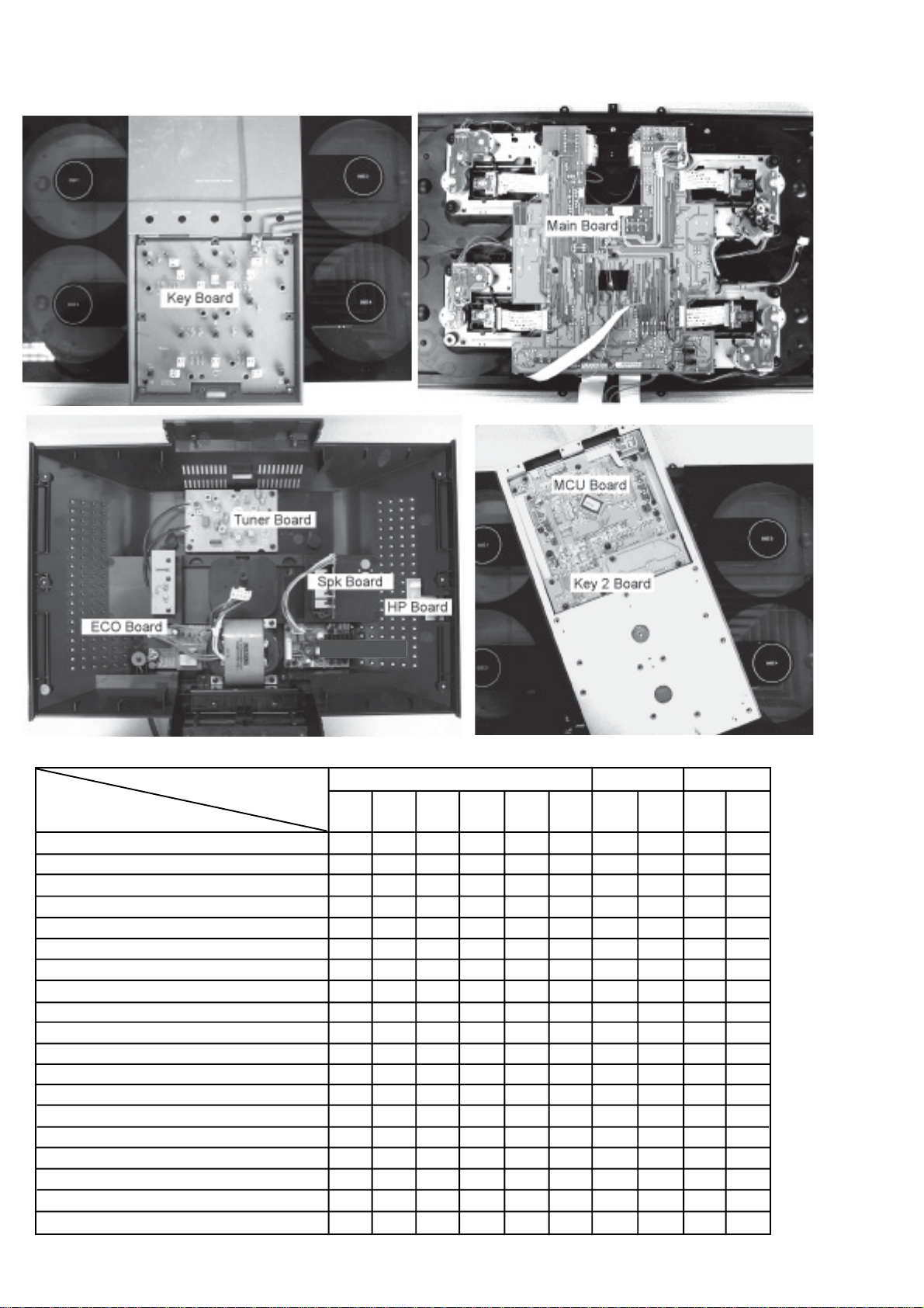
LACATION OF PCBS
1-2
VERSION VARIATIONS:
Type /Versions: MCM299
Features &
Board in used:
A
uxin/CDRin x
Line Out
Video Out
Surround Out
Subwoofer Out
Digital Out
Digital in
Matrix Surround
RDS/NEWS
Dolby Pro Logic (DPL)
Incredible Surround
Karaoke Features
Voltage Selector
ECO Power Standby (Clock Display Off) x
ECO6 Tuner Board - Systems Non-Cenelec
ECO6 Tuner Board - Systems Cenelec
USB Direct
/55 /37
x
x
x
/98

SPECIFICATIONS
1-3
6BEA>;>:G
DjiejiedlZg ######################## 'm'%L +%LGBH
H^\cVa"id"cd^hZgVi^d ####################################### t+%Y76
AG[gZfjZcXngZhedchZ ####### &(%¶&-`=o!£(Y7
HJ7;gZfjZcXngZhedchZ ##### *%¶ &'%=o!£(Y7
>cejihZch^i^k^in6JM ########################################## +%%bK
>beZYVcXZadjYheZV`Zgh ######################################### +:
>beZYVcXZ]ZVYe]dcZh ################# (':¶ &%%%:
######################################################################################### 1%#*L
&+:! &'%"&'#*`=o!&%I=9
89EA6N:G
;gZfjZcXngVc\Z ################################### )%"&-%%%=o
H^\cVa"id"cd^hZgVi^d ############################################ +%Y76
IdiVa]Vgbdc^XY^hidgi^dc ##################################### d(
AG;gZfjZcXngZhedchZ ###### &(%"&-`=o!£(Y7
HJ7;gZfjZcXngZhedchZ ###### *%"&'%=o!£(Y7
IJC:G
;BlVkZgVc\Z ################################### -,#*¶ &%-B=o
BLlVkZgVc\Z.`=o ############# *(&¶ &+%'`=o
BLlVkZgVc\Z&%`=o########### *(%¶ &,%%`=o
Ijc^c\\g^Y ############################################################ .$&%`=o
6ciZccV
¶;B ################################################################## (%% : L^gZ
¶BL ########################################################### AddeVciZccV
HE:6@:GH
7VhhgZ[aZmhnhiZb
9^bZch^dchlm]mY #### &,&m'.,m-.bb
HJ7LDD;:G
HjWldd[ZgcdibV\cZi^XVaanh]^ZaYZYYZh^\c#####
############################################################################################# &*Xb
>beZYVcXZ ####################################################################### +:
9^bZch^dchlm]mY ####################################################
##################################### ''%bbm(*%bbm(*,bb
LZ^\]i ########################################################################## ,#*`\
<:C:G6A>C;DGB6I>DC
68EdlZg########################### &&%¶&',$''%¶')%K0
####################################################### *%$+%=oHl^iX]VWaZ
9^bZch^dchlm]mY # )*%m((*m&&*bb
LZ^\]il^i]$l^i]djiheZV`Zgh ########### +#*$)#'`\
EdlZgXdchjbei^dc
6Xi^kZ ############################################################################## +%L
HiVcYWn ####################################################################### 1&*L
Specifications and external appearance are
subject to change without notice.
MEASUREMENT SETUP
CD
Use Audio Signal Disc SBC429 4822 397 30184 (replaces test disc 3)
L.P.F. = 13
th
order filter 4822 395 30204
1-4
DUT
Low pass filter 22kHz
L
R
S/N and distortion meter
e.g. Sound Technology ST1700B
LEVEL METER
e.g. Sennheiser UPM550
with FF-filter
SERVICE AIDS
1-5
Service Tools:
Universal Torx driver holder .................................4822 395 91019
Torx bit T10 150mm ...........................................4822 395 50456
Torx driver set T6-T20 .........................................4822 395 50145
Torx driver T10 extended .....................................4822 395 50423
Compact Disc:
SBC426/426A Test disc 5 + 5A ...........................4822 397 30096
SBC442 Audio Burn-in test disc 1kHz .................4822 397 30155
SBC429 Audio Signals disc .................................4822 397 30184
Dolby Pro-logic Test Disc ....................................4822 395 10216
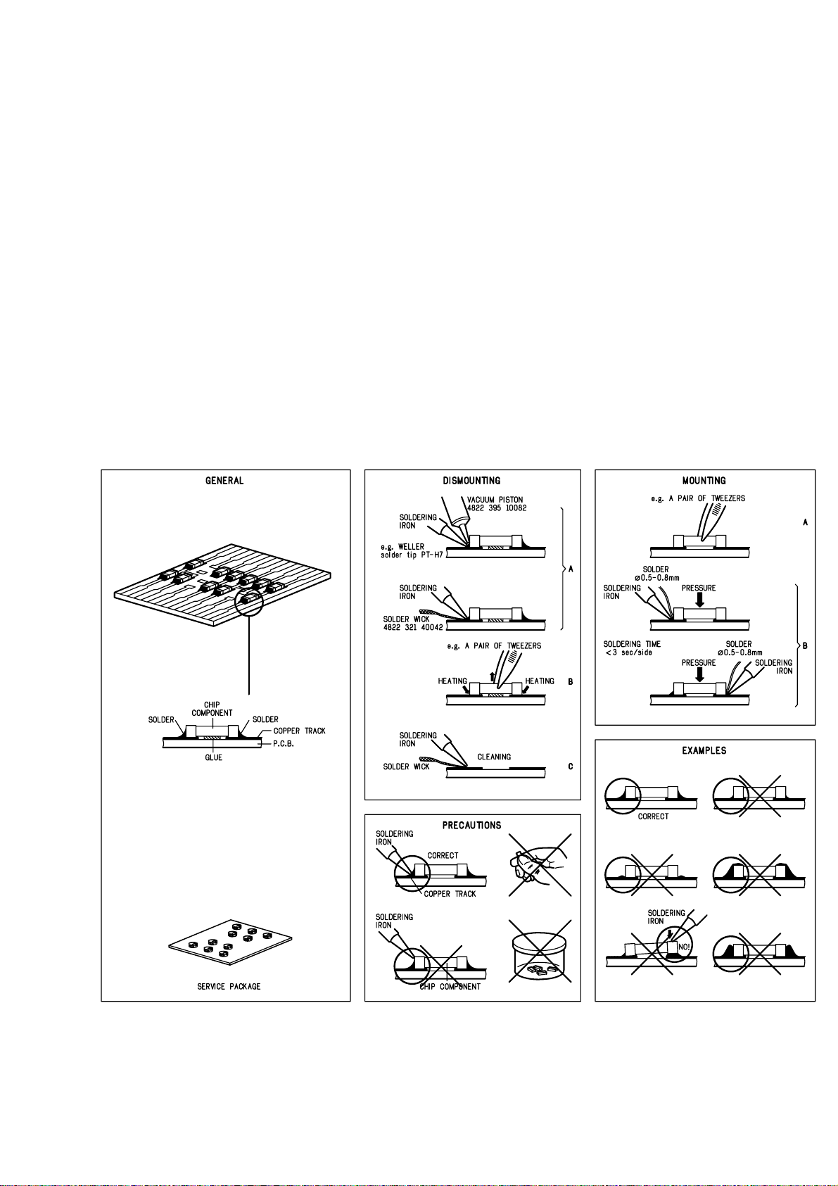
HANDLING CHIP COMPONENTS
ESD Equipment:
Anti-static table mat - large 1200x650x1.25mm ...4822 466 10953
anti-static table mat - small 600x650x1.25mm .....4822 466 10958
Anti-static wristband ............................................4822 395 10223
Connectorbox (1M
Extension cable
(to connect wristband to conn.box) ..........4822 320 11305
Connecting cable
(to connect table mat to conn.box) ...........4822 320 11306
Earth cable (to Connect product to mat or box) --4822 320 11308
Complete kit ESD3
(combining all above products) ...............4822 320 10671
Wristband tester ...................................................4822 344 13999
1) ..........................................4822 395 11307
1-6
GB
All ICs and many other semi-conductors are
susceptible to electrostatic discharges (ESD).
Careless handling during repair can reduce life
drastically.
When repairing, make sure that you are
connected with the same potential as the mass
of the set via a wrist wrap with resistance.
Keep components and tools also at this
potential.
Tous les IC et beaucoup d’autres
semi-conducteurs sont sensibles aux
décharges statiques (ESD).
Leur longévité pourrait être considérablement
écourtée par le fait qu’aucune précaution n’est
prise à leur manipulation.
Lors de réparations, s’assurer de bien être relié
au même potentiel que la masse de l’appareil et
enfiler le bracelet serti d’une résistance de
sécurité.
Veiller à ce que les composants ainsi que les
outils que l’on utilise soient également à ce
potentiel.
F
WARNING
ATTENTION
GB
Complete Kit ESD3 (small tablemat, wristband,
connection box, extention cable and earth cable) ...........4822 310 10671
Wristband tester ....................................................................4822 344 13999
ESD
D
WARNUNG
Alle ICs und viele andere Halbleiter sind
empfindlich gegenüber elektrostatischen
Entladungen (ESD).
Unsorgfältige Behandlung im Reparaturfall kan
die Lebensdauer drastisch reduzieren.
Veranlassen Sie, dass Sie im Reparaturfall über
ein Pulsarmband mit Widerstand verbunden
sind mit dem gleichen Potential wie die Masse
des Gerätes.
Bauteile und Hilfsmittel auch auf dieses gleiche
Potential halten.
ESD PROTECTION EQUIPMENT:
NL
Alle IC’s en vele andere halfgeleiders zijn
gevoelig voor electrostatische ontladingen (ESD).
Onzorgvuldig behandelen tijdens reparatie kan
de levensduur drastisch doen verminderen.
Zorg ervoor dat u tijdens reparatie via een
polsband met weerstand verbonden bent met
hetzelfde potentiaal als de massa van het
apparaat.
Houd componenten en hulpmiddelen ook op
ditzelfde potentiaal.
Tutti IC e parecchi semi-conduttori sono
sensibili alle scariche statiche (ESD).
La loro longevità potrebbe essere fortemente
ridatta in caso di non osservazione della più
grande cauzione alla loro manipolazione.
Durante le riparazioni occorre quindi essere
collegato allo stesso potenziale che quello della
massa dell’apparecchio tramite un braccialetto
a resistenza.
Assicurarsi che i componenti e anche gli utensili
con quali si lavora siano anche a questo
potenziale.
WAARSCHUWING
I
AVVERTIMENTO
GB
Safety regulations require that the set be restored to its original
condition and that parts which are identical with those specified,
be used
Safety components are marked by the symbol
!
.
NL
Veiligheidsbepalingen vereisen, dat het apparaat bij reparatie in
zijn oorspronkelijke toestand wordt teruggebracht en dat onderdelen,
identiek aan de gespecificeerde, worden toegepast.
De Veiligheidsonderdelen zijn aangeduid met het symbool
!
F
Les normes de sécurité exigent que l’appareil soit remis à l’état
d’origine et que soient utiliséés les piéces de rechange identiques
à celles spécifiées.
Less composants de sécurité sont marqués
!
D
Bei jeder Reparatur sind die geltenden Sicherheitsvorschriften zu
beachten. Der Original zustand des Geräts darf nicht verändert werden;
für Reparaturen sind Original-Ersatzteile zu verwenden.
Sicherheitsbauteile sind durch das Symbol
!
markiert.
I
Le norme di sicurezza esigono che l’apparecchio venga rimesso
nelle condizioni originali e che siano utilizzati i pezzi di ricambio
identici a quelli specificati.
Componenty di sicurezza sono marcati con
!
CLASS 1
LASER PRODUCT
GB
Invisible laser radiation when open.
Avoid direct exposure to beam.
Osynlig laserstrålning när apparaten är öppnad och spärren
är urkopplad. Betrakta ej strålen.
SF
Avatussa laitteessa ja suojalukituksen ohitettaessa olet alttiina
näkymättömälle laserisäteilylle. Älä katso säteeseen!
DK
Usynlig laserstråling ved åbning når sikkerhedsafbrydere er
ude af funktion. Undgå udsaettelse for stråling.
S
Warning !
Varning !
Varoitus !
Advarse !
GB
After servicing and before returning set to customer perform a leakage
current measurement test from all exposed metal parts to earth ground to
assure no shock hazard exist. The leakage current must not exceed
0.5mA.
F
"Pour votre sécurité, ces documents doivent être utilisés par
des spécialistes agréés, seuls habilités à réparer votre
appareil en panne".
1-7
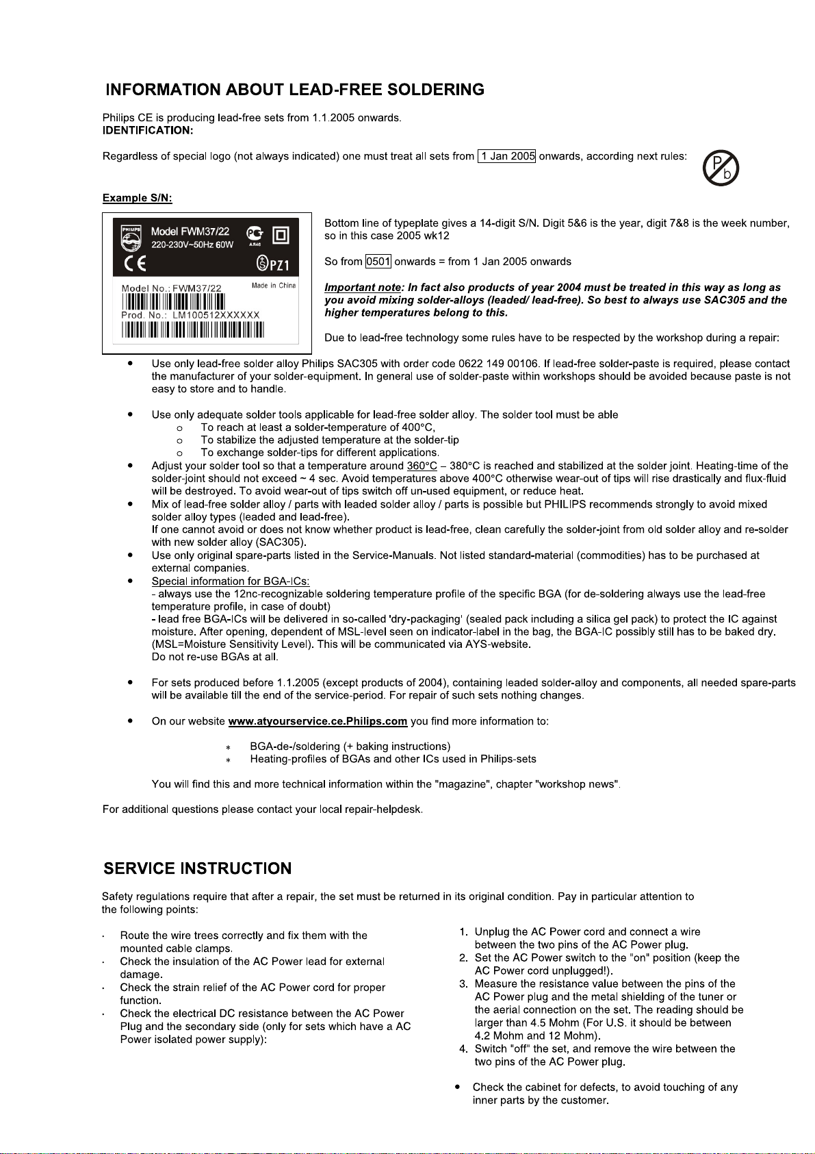
SERVICE TEST PROGRAM
3-1
To h ol d A LB U M+ &
PROGRAM depressed while
set on standby
3-1
Display shows the
ROM version
"Vy--y MTP xx-xx-2006"
(Main menu)
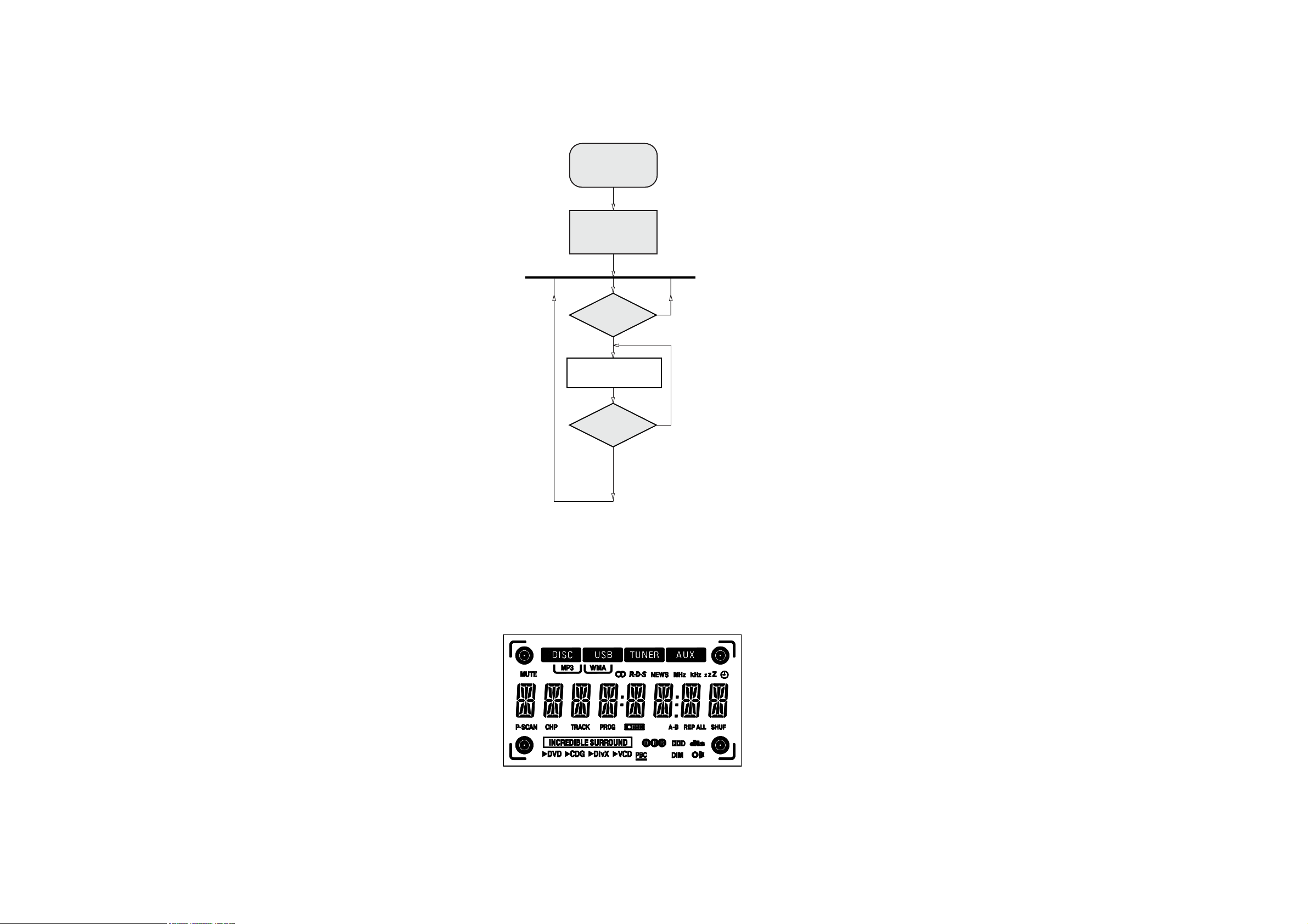
DISPLAY
TEST
ALBUM+ & PLAY
Button pressed?
Y
Display shows Figure 1
and switch all LEDs on
ALBUM+ & PLAY
Button pressed?
Y
V refers to Version
y--y refers to Software version number of the uProcessor
(counting up from 01 to 99)
xx refers to date number of the production.
N
N
Figure 1

SET BLOCK DIAGRAM
4-1
4-1

SET WIRING DIAGRAM
5-1
5-1

6-1 6-1
MAIN BOARD
TABLE OF CONTENTS
Main PCB - Layout Top View ........................................... 6-2
Main PCB - Layout Bottom View ..................................... 6-3
Main PCB - Circuit Diagram (Audio Part) ......................... 6-4
Main PCB - Circuit Diagram (CD Part) ............................. 6-5
Class D Power PCB - Layout Top View .......................... 6-6
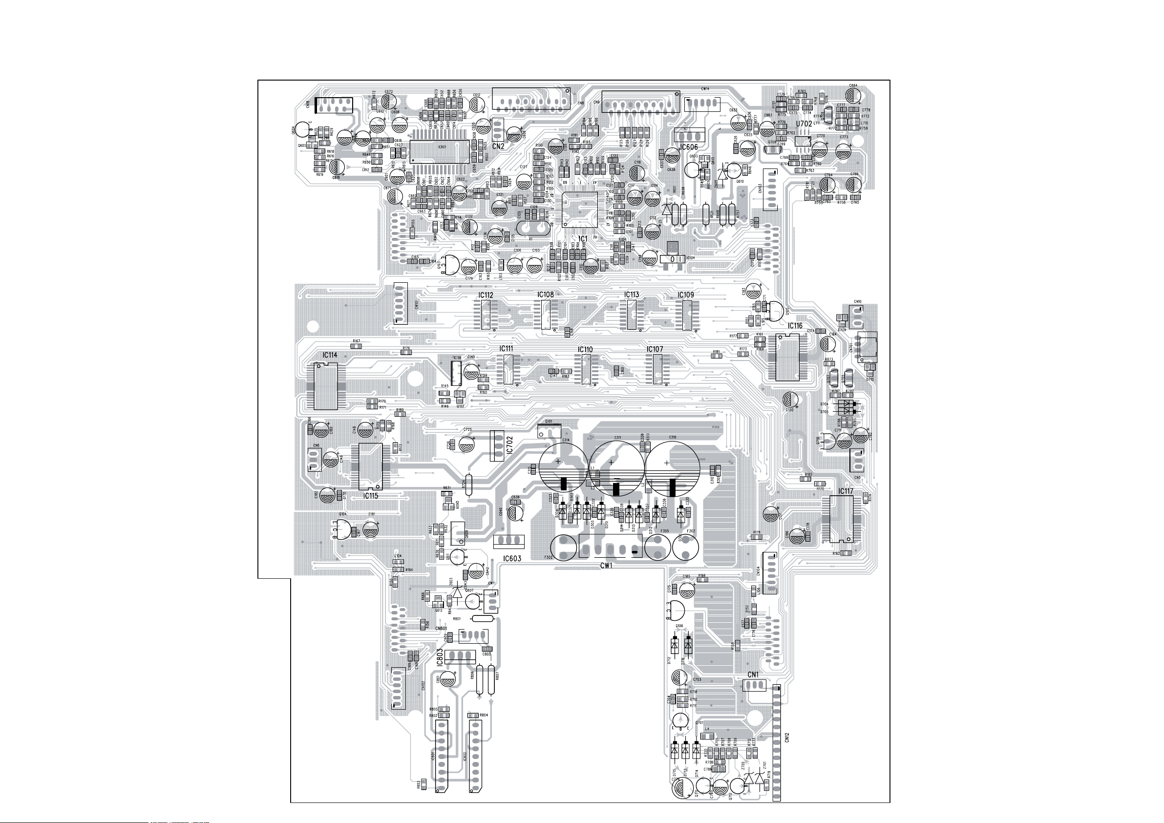
6-2 6-2
PCB LAYOUT - MAIN BOARD (TOP VIEW)
 Loading...