

Page 1
MCM279
Service AIDS & CD playability ...........................1-1...1-4
Specifications ................................................................2
Connection & Controls ...................................................3
Disassembly Instructions ...............................................4
Block & Wiring diagrams ................................................5
MAIN BOARD ................................................................6
KEY & USB JACK BOARD ............................................7
POWER & AMP BOARD ................................................8
EXPLODE DIAGRAM .....................................................9
SERVICE PARTLIST ....................................................10
FACTORY PARTLIST ...................................................11
3141 785 32151
Page 2
SERVICE AIDS
1-1
Service Tools:
Universal Torx driver holder .................................4822 395 91019
Torx bit T10 150mm ...........................................4822 395 50456
Torx driver set T6-T20 .........................................4822 395 50145
Torx driver T10 extended .....................................4822 395 50423
GB
All ICs and many other semi-conductors are
susceptible to electrostatic discharges (ESD).
Careless handling during repair can reduce life
drastically.
When repairing, make sure that you are
connected with the same potential as the mass
of the set via a wrist wrap with resistance.
Keep components and tools also at this
potential.
WARNING
GB
Safety regulations require that the set be restored to its original
condition and that parts which are identical with those specified,
be used
Safety components are marked by the symbol
!
.
Compact Disc:
SBC426/426A Test disc 5 + 5A ...........................4822 397 30096
SBC442 Audio Burn-in test disc 1kHz .................4822 397 30155
SBC429 Audio Signals disc .................................4822 397 30184
Dolby Pro-logic Test Disc ....................................4822 395 10216
ESD
CLASS 1
LASER PRODUCT
Lead free
Page 3
1-2
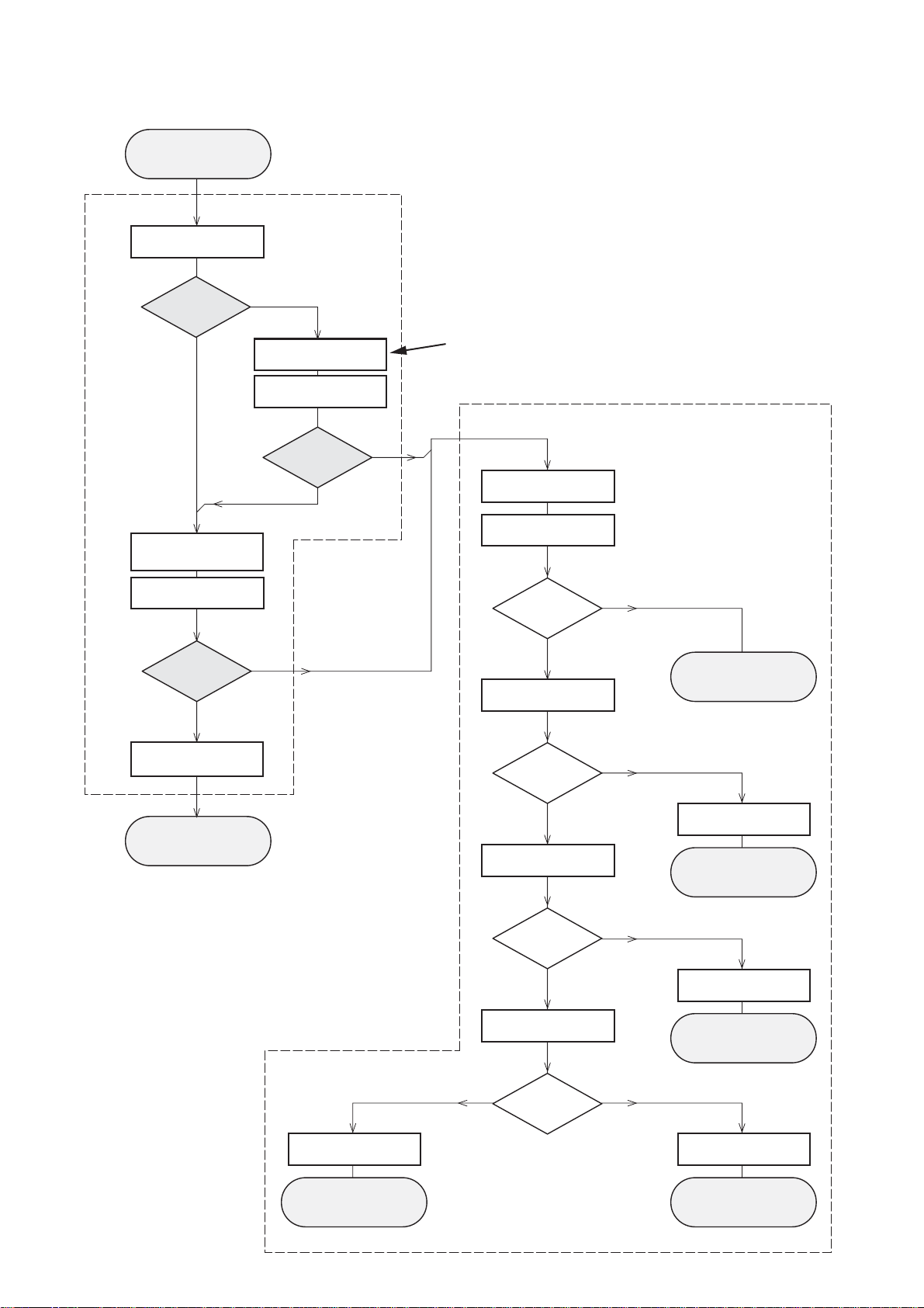
CD PLAYABILITY
Customer complaint
"CD related problem"
check playability
for at least 10 minutes
CHECK
playability
ok ?
Y
Play a CD
Set remains closed!
1
N
"fast" lens cleaning
check playability
playability
ok ?
Y
3
For flap loaders (= access to CD drive possible)
cleaning method
is recommended
4
Standard repair procedure
N
clean the lens
check playability
4
check playability
playability
ok ?
Y
add Info for customer
"SET OK"
return set
1
- 7
For description - see following pages
2
5
6
7
Y
return set
N
replace CD Drive
return set
N
replace CD Drive
return set
playability
ok ?
N
N
check "EYE-Pattern"
EYE-Pattern
ok ?
Y
check Laser current
Laser current
ok ?
Y
check CD Drive offsets
replace Signal Processor
return set
Y
CD Drive offsets
N
ok ?
replace CD Drive
return set
Page 4
1-3
CD PLAYABILITY
CHECK
1
PLAYABILITY CHECK
For sets which are compatible with
use CD-RW Printed Audio Disc....................7104 099 96611
TR 3 (Fingerprint)
TR 8 (600µ Black dot) maximum at 01:00
• playback of these two tracks without audible disturbance
playing time for: Fingerprint ≥
Black dot from 00:50 to 01:10
• jump forward/backward (search) within a reasonable time
For all other sets
use CD-DA SBC 444A..................................4822 397 30245
TR 14 (600µ Black dot) maximum at 01:15
TR 19 (Fingerprint)
TR 10 (1000µ wedge)
• playback of all these tracks without audible disturbance
playing time for: 1000µ wedge ≥10seconds
Fingerprint ≥10seconds
Black dot from 01:05 to 01:25
• jump forward/backward (search) within a reasonable time
CD-RW discs
10seconds
4
LIQUID LENS CLEANING
Before touching the lens it is advised to clean the
surface of the lens by blowing clean air over it.
This to avoid that little particles make scratches on
the lens.
Because the material of the lens is synthetic and coated
with a special anti-reflectivity layer, cleaning must be done
with a non-aggressive cleaning fluid. It is advised to use
“Cleaning Solvent B4-No2”, available with codenumber
4822 389 10026.
The actuator is a very precise mechanical component and
may not be damaged in order to guarantee its full function.
Clean the lens gently (don’t press too hard) with a soft and
clean cotton bud moistened with the special lens cleaner.
The direction of cleaning must be in the way as indicated in
the picture below.
2
CUSTOMER INFORMATION
It is proposed to add an addendum sheet to the set which
informs the customer that the set has been checked
carefully - but no fault was found.
The problem was obviously caused by a scratched, dirty or
copy-protected CD. In case problems remain, the customer
is requested to contact the workshop directly.
The lens cleaning (method 3) should be mentioned in the
addendum sheet.
The final wording in national language as well as the printing
is under responsibility of the Regional Service Organizations.
3
FAST LENS CLEANING (dry brush)
Use lens cleaning CD
SBC AC300...........................................9082 100 00043
Insert the lens cleaning CD, press PLAY and follow the
voice guide´s instructions on the CD.
Page 5
Sanyo DA12T3
CD Drive
A
A
F
C
B
E
C
D
E
VCC
B
VREF
F
D
9
10
11
12
13
14
15
16
1800
+5V_HF
VrefCD10
A
D
E
B
C
F
GND
8
E
D
A
B
C
F
Laser power control
100n
2878
470n
2876
3821
1R
1K
3823
2880
33p
+5V
BC807-40
7879
3817
47R
3820
4R7
47R
3819
1n
2879
2877
47u
1
8
4
7811-A
LM358D
3
2
10K
3822
47R
3818
2841
100n
47n
2869
+5V_HF
LASER DIODE
U >250mV
->Laser damaged !
4,6V
3V
3,3V
3,9V
2V
0,17V
0,17V
Sanyo
DA12T3
HF-Amplifier
D3
D2
D1
680R
3905
3903
3K3
BC847B
7877
47n
2818
1K5
3902
5
7
4
2
1
6
3
64
8
9
10
11
470R
3893
+3.3V
2K2
3908
10K
3923
BC847B
7878
BC847B
7876
4n7
2813
3896
100R
220u
2885
2881
560p
47n
2887
560R
3901
2883
470n
2817
4u7
3n3
2814
3898
220R
3895
27K
470n
2884
+3.3V
3909
820R
3907
100R
3920
33K
3897
2882
82p
3K3
3904
2K7
3899
3906
470R
+5V_HF
HFIN
VrefCD10
100p
28152816
22n
LDON
to 3826,3827
VREF GE
VDDA1
VRIN
VSSA1
ISLICE
LD
ON
D1
D2
D3
D4
HFIN
HFREF
IREF
CD_DA: 0V / CD_RW: 3V
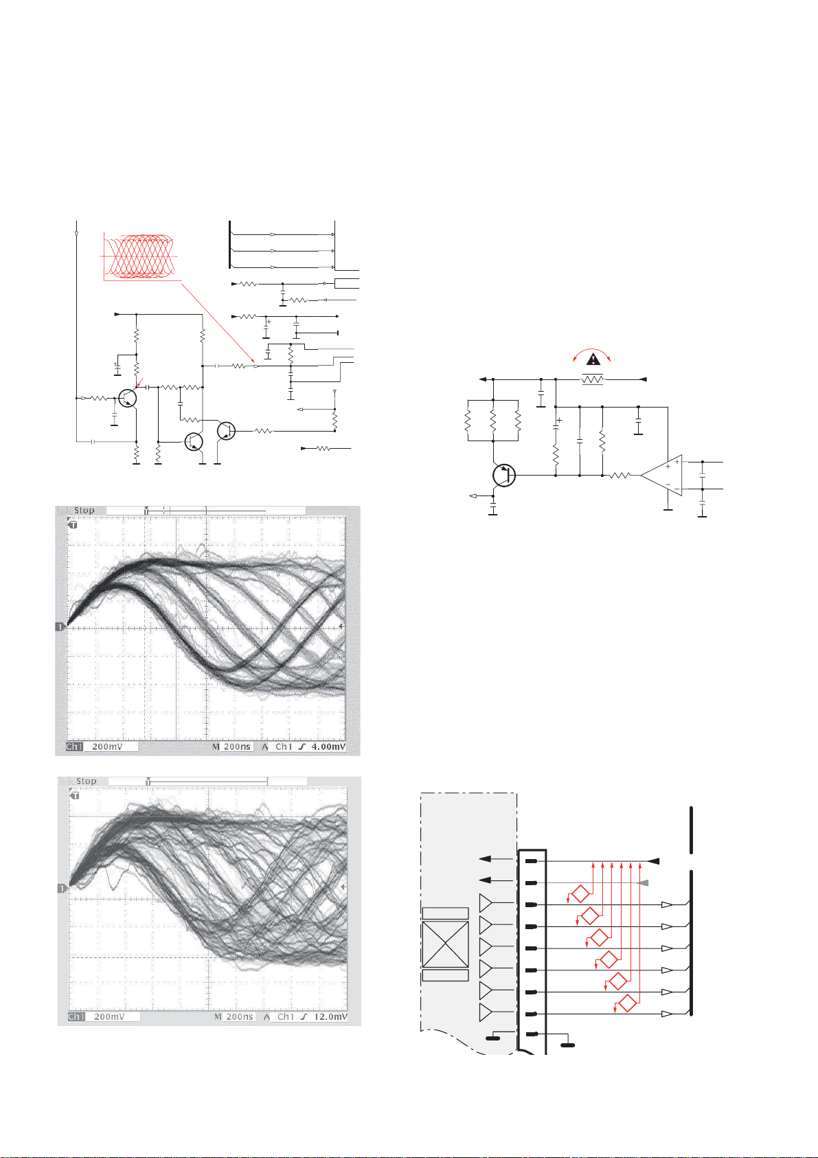
Σ
(A-D)
800mVpp
TB = 0.5µs/div
EYE-PATTERN
1,8V
1,2V
2,4V
2,6V
0,65V
CD PLAYABILITY CHECK
1-4
5
EYE-PATTERN SIGNAL – JITTER MEASUREMENT
Measure the signal on the input of the Signal processor
using an analog oscilloscope. Please find the exact
measuring point in your Service Manual.
See below examples of the signal. Amplitude should read at
least 700mVpp using SBC444A.
6
CD DRIVE – LASER CURRENT MEASUREMENT
The laser current can be measured as a voltage drop on a
resistor. The resistor is marked in every Service Manual.
The value depends on the type of CD drive.
typical value most probably defect
VAMxxxx : 150-230mV
MCDxx : 170-230mV
DA1x : 210-250mV ≥350mV
DA2x : 175-200mV
Use SBC444A (CD-DA) for measurement.
≥
350mV
≥
300mV
250mV
≥
If the oscilloscope shows a signal like the ‘bad’ one, and/or
the amplitude decreases within 1 minute - the CD drive has
to be replaced.
good
bad
7
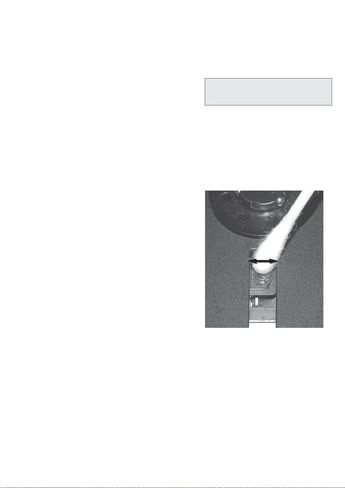
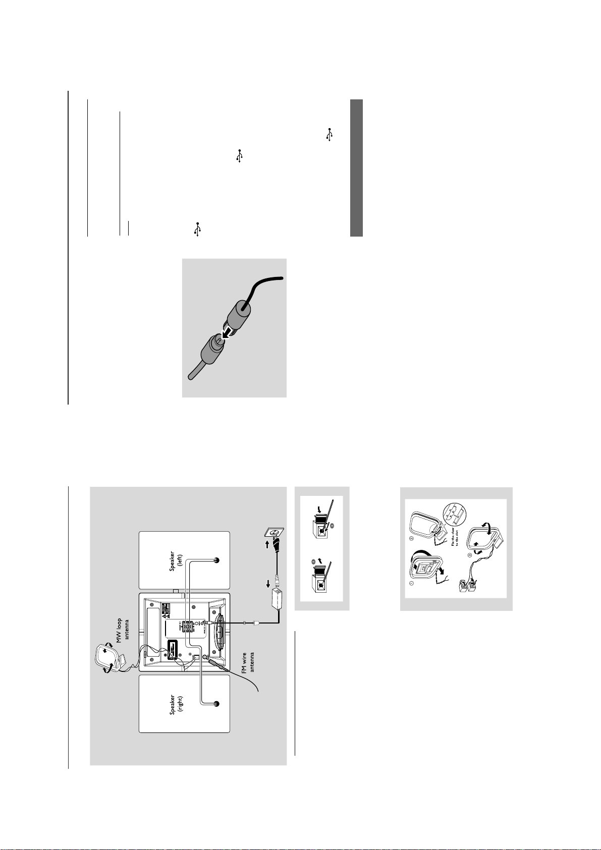
CD DRIVE – OFFSET MEASUREMENT
The photodiodes of the CD-drive may have an offset. These
offsets have to be compensated by the signal processor.
High offsets can lead to poor playability of some CDs
(skipping tracks).
To measure the offset values, start the
Program - section “Focus Test” without a CD.
The offsets can be measured with a DC Millivoltmeter
directly on the connector (see drawing below). Pin
numbering varies from drive to drive.
The values from diode A-D should read 0±10mV.
Diodes E and F are less critical.
If one of the offsets is higher than ±10mV the CD drive has
to be replaced. Otherwise replace the Signal Processor.
Service Test
Page 6

2 - 1
AMPLIFIER
Output power ................................................30 W RMS
Signal-to-noise ratio ....................................... ≥ 65 dBA
Frequency response ............. 100 – 18kHz, ± 3 dB
Input sensitivity AUX ....................... 0.5 V (max. 1 V)
Impedance loudspeakers .....................................≥ 6 Ω
Impedance headphones .................... 32
Ω
-1000
..................................................................................... <15mW
CD PLAYER
Frequency range ....................................... 100 – 18kHz
Signal-to-noise ratio ............................................ 65 dBA
TUNER
FM wave range ...................................87.5 – 108 MHz
MW wave range ................................ 531 – 1602 kHz
Number of presets ........................................................ 40
Antenna
FM .................................................................... 75 Ω wire
MW ......................................................... Loop antenna
USB PLAYER
USB ......................................................................... V2.0/ V1.1
......................................... support MP3 and WMA files
Number of albums/ folders ................ maximum 99
Number of tracks/titles ...................... maximum 999
Ω
SPEAKERS
Bass reflex system
Dimensions (w x h x d) .. 158 x 250x 185 (mm)
GENERAL INFORMATION
AC Power .......................... 110 – 240 V, 50 Hz/60Hz
Dimensions (w x h x d, with/without the stand)
............... 211 x 250 x 160/211 x 250 x 126 (mm)
Weight(with/without speakers) ......... 3.7 / 1.33 kg
Standby power consumption ............................ <2 W
Eco power standby ............................................... <1 W
Specifications and external appearance are
subject to change without notice.
Page 7
Connection
CONNECTION AND CONTROLS
3 - 1
Connection
Connecting a USB device or memory
Connecting an additional
appliance
FM antenna
VCR or other radiation source.
● Position the antenna as far as possible from a TV,
on the front
on the front panel of the main set.
card
By connecting a USB mass storage device
(including USB flash memory, USB flash players
or memory cards) to the Hi-Fi system, you can
enjoy the music stored on the external device
through the powerful speakers of Hi-Fi system.
Or,
panel of the main set.
for the devices with USB cable:
a. Insert one plug of the USB cable (not
supplied) to the socket
1 Insert the USB device’s USB plug into the socket
The wire antenna supplied can only be used to
receive nearby stations. For better reception we
recommend using a cable antenna system or an
outdoor antenna.
Extend the wire antenna and fit it to FM
ANTENNA as shown below
1
Insert the other plug of the USB cable to the
b.
USB output terminal of the USB device.
on the front panel of the main set.
the card reader to the socket .
optimal reception (as far away as possible from
the TV, VCR or other radiation sources)
Fix the antenna’s end to the wall.
3
Connecting a non-USB device
It is possible to use an additional appliance, e.g.
TV, VCR or CD recorder with the set. On
Helpful hints:
Or,
for the memory card:
a. Insert the memory card into a card reader
(not supplied).
b. Use a USB cable (not supplied) to connect
Note: If you are using a cable antenna system or
an outdoor antenna, fit the antenna plug, instead of
the wire antenna, to FM ANTENNA .
Move the antenna in different positions for
2
MCM279, you can playback music from an
external source.1Insert one plug of the audio cable (not supplied)
to the socket AUX IN at the rear panel of the
–To receive optimal radio reception, put the main
unit and the antennas as far away as possible from
the power adaptor.
main set.
Connect the other end of the audio cable to the
AUDIO OUT terminal of the additional
appliance.
2
Always refer to the owner’s manual of other
equipment for complete connection.
Helpful hints:
–
3 Select AUX mode on the set.
Antenna connections
MW antenna
Connect the supplied MW loop antenna to the
“AM aerial” terminal. Adjust the position of the
antenna for optimal reception.
6
9
Warning:
– Never make or change connections with
Rear connections
B
the mains supply switched on.
– Install your set near the AC outlet and
where the AC power plug can be reached
easily.
Use the supplied speakers only. Using other
speakers can damage the set or the sound
quality will be negatively affected.
A Speaker connections
(red and black) and the cable of the right
● Connect the cable of the left speaker to LEFT
(red and black) as follows:
RIGHT
speaker to
a. Press the clip of the red terminal and fully
insert the stripped portion of the colored (or
marked) speaker cable into the socket, then
release the clip
Press the clip of the black terminal and fully
b.
insert the stripped portion of the black (or
unmarked) speaker cable into the socket, then
release the clip
Page 8
CONNECTION AND CONTROLS
set on and selects sound source CD, USB,
SOURCE
9 OPEN/CLOSE 0
0 DBB (Dynamic Bass Boost)
!
– turns the bass enhancement on/off
– opens/closes the CD door.
AUX
– selects sound source CD, USB, TUNER, or
TUNER or AUX
– In standby or Eco Power mode: switches the
STOP
@
– CD/USB: stops playback; erase a program
3 - 2
switches between
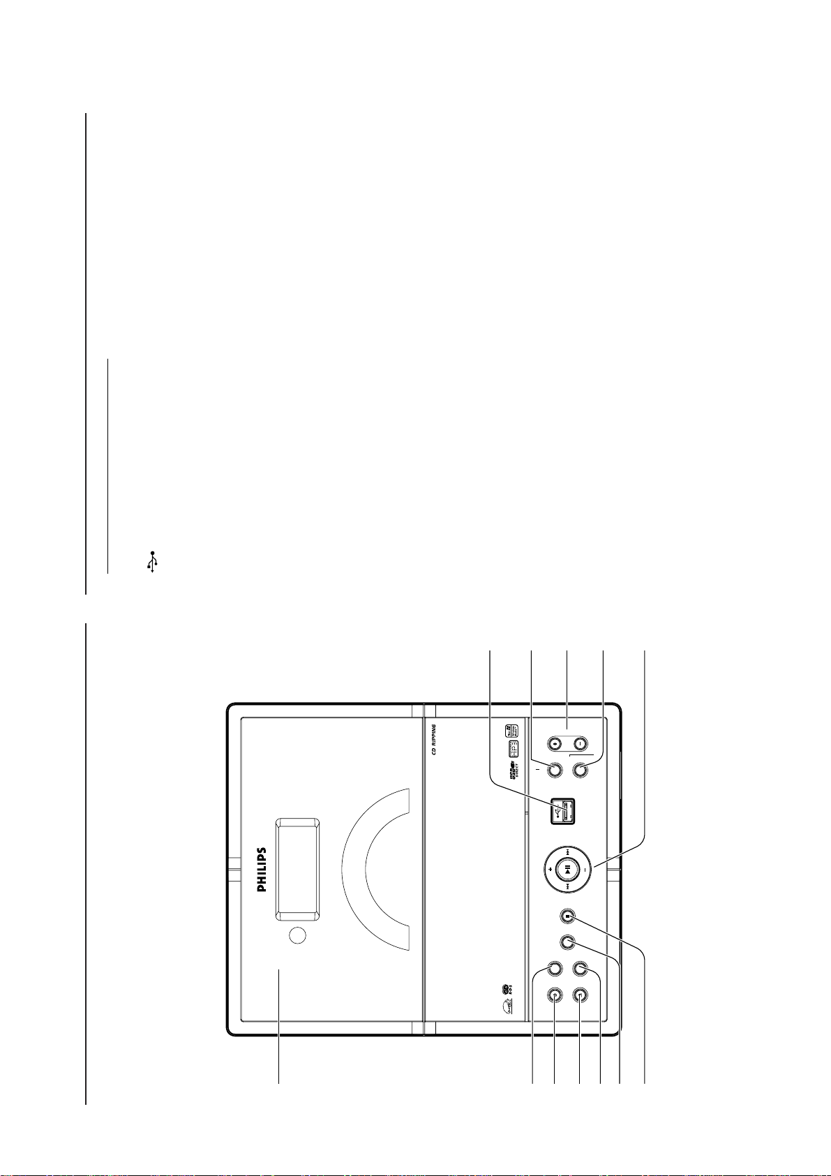
Controls on the set (illustrations
Controls
on page 3)
1
– jack for the external USB mass storage device
2 PROGRAM
programs tracks
programs preset radio stations
– CD/USB:
– Tuner:
VOLUME
– adjusts the volume level
– Clock/Timer: adjusts the hours and minutes
3
DISPLAY/CLOCK
- displays the set time
– Clock:
4
enters the clock setting mode
(press and hold for more than 2 seconds)
clock
display and playback display
during playback
- In standby mode:
– TUNER/Audio CD/AUX:
– MP3/WMA files: displays disc information
MICRO SYSTEM MCM279
ALBUM/ PRESET + /-
5
4 / ¢
backwards/forwards
– CD/USB: selects albums (for MP3/WMA only)
– TUNER: selects a preset radio station
– CD/USB: skips or searches CD tracks/titles
1
4mm
– Tuner: tunes to radio stationsÉÅ– CD/USB: starts or pauses playback
2
VOLUMEPROGRAM
ALBUM/PRESET
Always point the remote control
towards this sensor.
6 IR
– sensor for the infrared remote control
Helpful hints:
7 DSC (Digital Sound Control)
4
3
DISPLAY/CLOCK
JAZZ, POP, CLASSIC, OFF
– selects predefined sound settings: ROCK,
5
– press briefly to switch the set on or off (standby/
8 STANDBY-ON/ ECO POWER
ECO POWER);
– In standby or Eco Power mode: press and
lights up red when the set is
hold to toggle between Standby and ECO
POWER mode (power-saving mode)
Red indicator:
switched to ECO POWER mode
–
Controls
6
IR
MPATIBLE
RW CO
-
R/CD
-
CD/CD
-
MP3
-
WMA
ECO POWER
7
SOURCE STOP
DSC
DBB
ON
-
ANDBY
OPEN/CLOSE
ST
@
!
0
9
8
Page 9

CONNECTION AND CONTROLS
Mounting the stand onto the set
MCM279 is supplied with a stand, you may
attach or detach the stand to/from the main set.
Placing MCM279
Locate the bottom of the main unit and find the
slot, then slide the stand in the slot until it stops,
as indicated in the figure below.
1
3 - 3
Controls
Controls
copies one file or all files of a disc to an
USB:
external portable USB storage device/MP3
–
– set the sleep timer
3 SLEEP
4 MUTE
5
4$
player.
& 0
– switches the sound off temporarily
during playback
switches the timer on/off
USB REC
– MP3/WMA files: displays disc information
$ DISPLAY
AUX
– selects the audio input from an additional
–
% TIMER ON/OFF
^
switches the set
connected appliance
on and selects the audio input from an
additional connected appliance
– In standby/Eco-power mode:
123
@
#
Remote control
– opens/closes the CD door.
à / á
– CD/USB: skips or searches CD tracks
5
6
7890!
^
*
&
ë
í/
– CD/USB: selects previous/next track
*
backwards/forwards
– Tuner: tunes to radio stations
(
Numeric keypad (0-9)
– CD/USB: stops playback; erase a program
( 9
)
selects the next/previous album (for
3 / 4
CD/USB:
MP3/WMA only)
–
– Tuner: selects a preset station
)
¡%™
– selects track or station number
ÉÅ
DSC (Digital Sound Control)
JAZZ, POP, CLASSIC, OFF™DBB (Dynamic Bass Boost)
– selects predefined sound settings: ROCK,
¡
– CD/USB: star ts or pauses playback.
– turns the bass enhancement on/off
USB DEL
USB device.
adjusts the volume level
– deletes one file or all files stored on the external
6
Notes for remote control:
– First select the source you wish to
–
7 VOL +/-
CD, TUNER).
control by pressing one of the source select
keys on the remote control (for example
System)
Data
adjusts the hours and minutes
REPEAT–selects continuous playback9SHUFFLE
– Clock/Timer:
8
).
ë
,
í
,
selects random playback0PROG–CD/USB: programs tracks
–
press and
RDS/NEWS
!
– Tuner: programs preset radio stations
– Tuner: selects RDS (Radio
ÉÅ
USB source
BBBB
ECO POWER);
In standby or Eco Power mode:
hold to toggle between Standby and ECO
POWER mode (power-saving mode)
– Then select the desired function (for
example
B
press briefly to switch the set on or off (standby/
Source buttons
USB
selects
TIMER
for more than 2 seconds)
information
– CD/USB/AUX: activates/deactivates news
In standby/Eco-power mode: switches the set
on and selects USB source.
CD
CLOCK–Clock:
– enters the timer setting mode (press and hold
@
#
switches the set
source
selects CD
on and selects CD source.
In standby/Eco-power mode:
enters the clock
In standby mode:
- displays the set time
-
setting mode (press and hold for more
than 2 seconds)
switches the set
TUNER source and toggles between the
TUNER
selects
wavebands: FM and MW
In standby/Eco-power mode:
TUNER/Audio CD/AUX: switches between
clock display and playback display
–
source
TUNER
on and selects
Page 10

DISASSEMBLY DIADRAMS
4 - 1
4 - 1
A. Remove stand
Rlease click and pull it out.
B. Remove Top Cabinet
Remove screws MP 3x10 - 6 pcs.
C. Remove Amplif ier board
C1: Remove screws 2 pcs.
C2: Remove screws 2 pcs.
C1
C1
C2
C2
D. Remove Main board
D1:Remove screws MP 3x10 - 3 pcs.
D1
D2:Remove screws MP 3x10 - 3 pcs.
Then remove lens frame cosmetic top_right&left
D2
E. Remove Key board
E1:Remove screws MP 2x8 - 8 pcs.
Then remove lens frame cosmetic botom_right&left
E1
E1
Page 11

SET BLOCK DIAGRAM
5 - 1
5 - 1
Page 12

SET WIRING DIAGRAM
5 - 2
5 - 2
Page 13

CIRCUIT DIAGRAM - MAIN BOARD - PART1
6-1
6-1
Page 14

CIRCUIT DIAGRAM - MAIN BOARD - PART2
6 - 2
6 - 2
Page 15

6 - 3
6 - 3
LAYOUT DIAGRAM -
MAIN BOARD
Page 16

KEY & USB JACK BOARD
7 - 1
7 - 1
Page 17

8 - 1
8 - 1
CIRCUIT DIAGRAM
POWER & AMP BOARD
-
Page 18

8 - 2
LAYOUT DIAGRAM - POWER & AMP BOARD
8 - 2
Page 19

EXPLODE DIAGRAM
9-1
9-1
Page 20

ACCESSORY PARTS
T
2
S
R
A
B
K
R
)
R
A
C
R
10-1
! 9940 000 02082 A
9965 100 00308 FM ANT WIRE 75R L1.0M
! 9965 100 07794 SWITCHING POWER ADAPTOR 19V/4A
9965 100 00131
9965 100 07795 SPEAKER BOX FOR MCM279//00(for /55)
9965 100 10123 SPEAKER BOX FOR MCM279(for /12)
9965 100 07796 RC "PHILIPS" FOR MCM279
9965 100 07001 STAND PORTION OF MCM238/1
99651 000 0132 CONVERSION MAINS PLUG ADAPTOR (for /55)
C CORD VDE 2C L=1.5M
A
M LOOP ANT 18.1uH 8
MECHNICAL&MISCELLANEOUS PART
12 99651 000 9789 CABINET FRONT V1
2 9965 100 07777 LENS-SLIDE DOOR
71 9965 100 07778 CABINET REA
5 9965 100 07798 CARRIER - SLIDE DOOR -R
7 9965 100 07779 CARRIER - SLIDE DOOR -L
32 9965 100 07780 RACK BAR
13 9965 100 07781 LENS-CD AMBI LIGHT GUIDE
16 9965 100 06985 BUTTON POWER
47 9965 100 06982 BUTTON SET FUNCTION51 9965 100 06983 BUTTON SET FUNCTION-
52 9965 100 06980 BRACKET PLAY BUTTON
50 99651 001 0192 BUTTON SET-NAVIGATION V1
14 9965 100 06981 COVER POWER BUTTON
6 99651 000 9788 DOOR CD - SLIDE V1
44 99651 000 9790 DOOR CD - ROTATED V1
17 9965 100 07784 GEAR-ROTATED DOOR RAC
19 9965 100 07785 GEAR-SLIDE DOO
46 9965 100 07786 CONTROL PANEL (for /12)
46 9965 100 07950 CONTROL PANEL (for /55)
1 9965 100 07787 COVER- ROTATED CD DOOR(for /12)
1 9965 100 07951 COVER- ROTATED CD DOOR (for /55)
4 9965 100 07788 FRAME-LCD CHROME
48 9965 100 06991 COVER PLAY BUTTON(for /12)
48 9940 000 04315 COVER PLAY BUTTON(for /55)
49 9965 100 06992 COVER NAVIGATION BUTTON(for /12
49 9940 000 04309 BUTTON FW/FF (for /55)
23 9940 000 04317 GEAR WHEEL A
22 9940 000 04318 GEAR WHEEL B
28 9940 000 04316 PULLEY SERVO MOTO
15 9965 100 07789 CUSHION CD MECHANISM
64 9940 000 04323 CD DAMPER (BLACK) 20DEG
65 9965 100 07790 CD DAMPER (BLACK) 30DEGREE
74 9965 100 07791 RUBBER FOOT FOR FRAME-COSMETI
18 9965 100 07792 SHAFT FOR MCM279
24 9940 000 04325 BELT MOTO
CDMECH 9965 100 10437 CD MECHANISM M93BGP-BF
FFC1 9965 100 10376 FFC CBL 20PIN P=1.25MM L=120MM
FFC2 9965 100 07773 FFC CABLE10PIN P=1.25MML=130MM
FFC3 9965 100 10375 FFC CABLE 12PIN P=1.0MM L=70MM
Page 21

10-2
D
)
R
ELECTRICAL PARTS - MAIN BOAR
70 9965 100 00946 TUNER MODULE AM/FM ENG07821QF(for /12
70 9965 100 01360 TUNER MODULE ENG06835QF.(for /55)
IC19 9965 100 07759 IC PCF8563T CLOCK SOP8
X4 9965 100 07758 CRYSTAL 32.768KH Z/3*8 12.5pF
IC7 9965 100 07760 IC AM7072A L/FMOTORDRIVER DIP8
MOTO
Q28 9940 000 05691 TRANSISTOR PNP BC869SOT-89
Q29 9965 100 07743 CH-TRANSISTOR,BC817-40 SOT-23
R1 9940 000 04221 FUSE RES 2.2R 1/4W +/-5%
D3 9965 100 07742 CH-DIODE, HIGHBAS316SOT323
IC10 9940 000 05687 IC 16M SDRAM K4S161622H-UC60
IC15 9965 100 07747 IC, HEF4094BT PHILIPS SO16
IC16 9965 100 01347 IC ET2314 SOUND SO28
IC2 9965 100 07747 IC, HEF4094BT PHILIPS SO16
IC6 9965 100 07745 IC, OPT30 RESET OPTEK SOP-8
IC8 9965 100 07744 IC, SCF5250
IC9 9965 100 07746 IC, 8M FLASH KH29LV800CTTC-70G
Q17 9965 100 07743 CH-TRANSISTOR,BC817-40 SOT-23
Q5 9965 100 07743 CH-TRANSISTOR,BC817-40 SOT-23
X1 9965 100 06950 CRYSTAL 8.4672MHZ+/-20PPM 30PF
IC12 9965 100 07750 IC, SAA7824HL LQFP80
IC4 9965 100 06955 IC, D9258 MOTOR DRIVERCD
IC5 9965 100 07749 IC, YD4558 SOP8
L1 9965 100 07751 INDUCTOR RTB6046-101K-1A 100UH
Q10 9965 100 07748 CH-TRANSISTOR,BC807-40SOT-23
9940 000 04253 DC MOTOR JQ32-55K415 DC3V
Q3 9965 100 07748 CH-TRANSISTOR,BC807-40SOT-23
Q4 9965 100 07743 CH-TRANSISTOR,BC817-40 SOT-23
Q8 9965 100 07743 CH-TRANSISTOR,BC817-40 SOT-23
Q9 9965 100 07743 CH-TRANSISTOR,BC817-40 SOT-23
D2 9965 100 07752 CH-ZENER DIODE, UDZS 5.1B
IC17 9965 000 41703 IC, BH4453F
JK101 9940 000 03318 HP JACK D3.6MM
Q15 9965 100 07743 CH-TRANSISTOR,BC817-40 SOT-23
Q24 9965 100 07743 CH-TRANSISTOR,BC817-40 SOT-23
Q34 9965 100 07748 CH-TRANSISTOR,BC807-40SOT-23
Q6 9965 100 07743 CH-TRANSISTOR,BC817-40 SOT-23
Q7 9965 100 07743 CH-TRANSISTOR,BC817-40 SOT-23
IC1 9940 000 05675 IC AZ1117H-5.0 TRE1 REGULATOR
IC3 9965 000 41892 IC AZ1117H-3.3 REGULATOR
Q1 9965 100 07753 CH-PWR TRANSISTOR PNP 2SB1182
Q2 9965 100 07743 CH-TRANSISTOR,BC817-40 SOT-23
Q30 9940 000 05691 TRANSISTOR PNP BC869SOT-89
Q31 9940 000 05691 TRANSISTOR PNP BC869SOT-89
Q33 9965 100 07743 CH-TRANSISTOR,BC817-40 SOT-23
D5 9965 100 07092 ZENER DIODE 5.6V 1/2W
IC14 9940 000 04239 IC SAA6588T RADIO RECEIVERS
Q16 9965 100 07743 CH-TRANSISTOR,BC817-40 SOT-23
X3 9940 000 04238 CRYSTAL 4.332MHZ +/-20PPM
IC11 9940 000 05692 IC ISP1160BD/01 USB CONTROLLER
Q11 9940 000 05691 TRANSISTOR PNP BC869SOT-89
Q12 9965 100 06966 MOSFET P-CH APM2301 SOT-23
Q13 9965 100 07743 CH-TRANSISTOR,BC817-40 SOT-23
Page 22

10-3
D
Y
D
D
ELECTRICAL PARTS - MAIN BOAR
X2 9965 100 07754 CRYSTAL 6MHZ/3*8 20PF +/-20ppm
IC13 9965 100 07755 IC ET8862Q PQFP64 LCD DRIVER
IR101 9965 000 41893 IR RECEIVER BRM-4050-8-FB2.2
LCD101 9965 100 07756 LCD FSTN TRANS 60X31.5X2.8mm
LED2 9940 000 05678 LED 3MM SUPER BLUE
LED3 9940 000 05678 LED 3MM SUPER BLUE
LED4 9965 100 07006 LED 4.8X4.4MM ROUND BLUE X
Q18 9965 100 07743 CH-TRANSISTOR,BC817-40 SOT-23
Q19 9965 100 07743 CH-TRANSISTOR,BC817-40 SOT-23
ELECTRICAL PARTS - DOOR BOAR
S1 9965 100 07757 DOOR SWITCH MST-002
S2 9965 100 07757 DOOR SWITCH MST-002
ELECTRICAL PARTS - KEY BOAR
JK1 9940 000 04263 USB JACK USB-1400A 4P
LED1 9965 100 00292 LED 3MM 3R4HD-7(RED) TAPING
Q14 9965 100 07743 CH-TRANSISTOR,BC817-40 SOT-23
T 9940 000 04259 SWITCH TACT TSA-06430-150
Page 23

10-4
D
A
A
A
T
T
ELECTRICAL PARTS - POWER& BOAR
D604 9965 100 06964 DIODE 1N5819 DO-41
JK601 9965 100 06969 DC JACK 3PIN DC-005 DIA6.3MM
JK602 9940 000 03318 HP JACK D3.6MM
L601 9965 100 07769 INDUCTOR15UH+/-20%DCR=0.045ohm
L602 9965 100 07769 INDUCTOR15UH+/-20%DCR=0.045ohm
L603 9965 100 07769 INDUCTOR15UH+/-20%DCR=0.045ohm
L604 9965 100 07769 INDUCTOR15UH+/-20%DCR=0.045ohm
L605 9965 100 07771 TOROID INDUCTOR 8UH 3.2
L606 9965 100 07771 TOROID INDUCTOR 8UH 3.2
L607 9965 100 07770 INDUCTOR47UH 7E05NBSMDIm=960m
L608 9965 100 07768 INDUCTOR220UH+/-20%DCR=0.45ohm
L609 9965 100 06959 28UH CORE:T9X5X3 6TURNS 715OHM
Q601 9965 100 06953 CH-TRANSISTOR, BC847C SOT-23
Q602 9965 100 06953 CH-TRANSISTOR, BC847C SOT-23
Q603 9965 100 06953 CH-TRANSISTOR, BC847C SOT-23
Q605 9940 000 05691 TRANSISTOR PNP BC869SOT-89
Q606 9965 100 06953 CH-TRANSISTOR, BC847C SOT-23
Q607 9965 000 41725 TRANS. 2SB1370PNP TO-220FP
Q608 9965 000 41726 TRANS. 2SC5343 NPN TO-92
Q609 9940 000 05649 TRANSISTOR DTA114YSAPNP SP
Q610 9965 000 41700 CH-TRANS. DTC114YKA NPN
Q611 9965 100 06953 CH-TRANSISTOR, BC847C SOT-23
Q613 9965 100 06953 CH-TRANSISTOR, BC847C SOT-23
Q614 9965 100 07765 CH-TRANSISTOR BC857C INFINEON
SP601 9940 000 01619 SP TERMINAL MSP-134V-05
U601 9965 100 07766 IC TDA8932BT/N2C CLASS D POWER
U602 9965 100 07766 IC TDA8932BT/N2C CLASS D POWER
U604 9965 100 07767 IC AZ34063AM-E1 DC-TO-DC CONV
ZD601 9965 100 07761 ZENER DIODE 5V1 1/2W TAPING.
ZD602 9965 100 07762 ZENER DIODE 9V1 1/2W TAPING.
ZD603 9965 100 07764 ZENER DIODE 22V 1/2W TAPING.
Note: Only these parts mentioned in the list are normal
service parts.
Page 24

,
,
,
,
,
11-1
FACTORY PARTLIST
Level Item Component Desc Unit Qty Location AppForm
0 0010 9008-027900012 PHILIPS MCM279//12 SET 1.000
.1 0010 8900-070400100 ELECTRICAL SECTION OF MCM279//12(W/RDS) SET 1.000
..2 0010 8901-070400100 MAIN PWB ASSEMBLY OF MCM279//12 SET 1.000
...3 0010 3702-027900130 MAIN PWB:DOUBLE 175x204x1.6MM FR4 MCM279-
...3 0020 8903-070400100 MCU SECTION ASSEMBLY OF MCM279/12 SET 1.000
....4 0010 1123-106033050 TANT. CH-CAP 10UF 6.3V +/-20% 3216-A TYP
....4 0020 1132-225083020 CAP ELECT, 2.2UF 50V +/-20% 4X5 TAPING PC
....4 0030 1132-226053020 CAP ELECT 22UF 16V +/-20% 4X5MM(TAPING PH=2.5MM) PC 1.000 C139
....4 0040 1132-476083100 CAP ELECT, 47UF 50V +/-20% 6.3X11 TAPING PC 3.000 C56,C66,C171
....4 0050 1132-107043060 CAP ELECT, 100UF 10V +/-20% 5X11 TAPING PC 2.000 C57,C112
....4 0070 1132-227053060 CAP ELECT, 220UF 16V +/-20% 5X11 TAPING PC 1.000 C143
....4 0080 1121-102082020 CH-CAP, CER1000PF50V+/-10%0603 PC 3.000 C60,C79,C173
....4 0090 1121-103052020 CH-CAP, CER 0.01UF16V+/-10%0603 PC 1.000 C77
....4 0100 1121-104052020 CH-CAP, CER 0.1UF16V+/-10%0603 PC 26.000
....4 0110 1121-105044020 CH-CAP, CER1UF10V +80%/-20%0603 PC 1.000 C82
....4 0120 1121-220051020 CH-CAP, CER 22PF16V+/-5%0603 PC 2.000 C58,C59
....4 0150 1121-222052020 CH-CAP, CER 2200PF 16V+/-10%0603 PC 2.000 C
....4 0160 1121-224084030 CH-CAP, CER0.22UF50V+80%-20%0805 PC 2.000 C
....4 0170 1121-225032020 CH-CAP, CER2.2UF6.3V+/-10%0603 PC 1.000 C54
....4 0190 1121-475044020 CH-CAP, CER4.7UF 10V+80%-20%0603 PC 1.000 C
....4 0200 1121-681051020 CH-CAP, CER 680PF16V+/-5%0603 PC 3.000 C61,
....4 0210 1221-000052020 CH-RES, 0R1/10W+/-5%0603 PC 4.000 R28,R243,
....4 0220 1221-100052020 CH-RES,10R1/10W+/-5%0603 PC 2.000 R78,R80
....4 0230 1221-470052020 CH-RES,47R1/10W+/-5%0603 PC 5.000 R92,R93,R94,R207,R272
....4 0240 1221-101052020 CH-RES,100R1/10W+/-5%0603 PC 22.000
....4 0250 1221-102052020 CH-RES,1K1/10W+/-5%0603 PC 11.000
....4 0256 1221-272052020 CH-RES,2.7K0.1W+/-5%0603 PC 2.000 R238,R239
....4 0257 1221-332052020 CH-RES, 3.3K1/10W+/-5%0603 PC 2.000 R81,R10
....4 0260 1221-472052020 CH-RES, 4.7K1/10W+/-5%0603 PC 10.000
....4 0270 1221-103052020 CH-RES,10K1/10W+/-5% 0603 PC 14.000
....4 0280 1221-123052020 CH-RES, 12K1/10W+/-5%0603 PC 4.000 R209,R21
....4 0290 1221-153052020 CH-RES,15K1/10W+/- 5% 0603 PC 3.000 R142,R1
....4 0300 1221-223052020 CH-RES, 22K1/10W+/-5%0603 PC 7.000
....4 0310 1221-473052020 CH-RES, 47K1/10W+/-5%0603 PC 1.000 R76
....4 0320 1221-104052020 CH-RES, 100K1/10W+/-5%0603 PC 4.000 R87,R11
....4 0330 1221-154052020 CH-RES, 150K1/10W+/-5%0603 PC 1.000 R77
....4 0340 1221-105052020 CH-RES, 1M1/10W+/-5%0603 PC 1.000 R129
....4 0350 1001-084672220 CRYSTAL, 8.4672MHZ +/-20PPM 30PF 3x8 PC 1.
....4 0360 1311-141480010 DIODE 1N4148. PC 1.000 D4
....4 0370 1321-003160010 CH-DIODE, HIGHBAS316SOT323 PC 1.000 D3 FA030154
....4 0380 1422-817400010 CH-TRANSISTOR,BC817-40 SOT-23 PC 2.000 Q5,Q17 FA030192
....4 0390 1502-002314010 IC ET2314 SOUND SO28 PC 1.000 IC16 FAP070031
....4 0400 1506-005250000 IC, SCF5250 PC 1.000 IC8 FA050919
....4 0410 1508-000030000 IC, OPT30 RESET OPTEK SOP-8 PC 1.000 IC6 FA050727
....4 0420 1511-829800160 IC, 8M FLASH KH29LV800CTTC-70G (OPT48) TSOP48 PC 1.000 IC9
....4 0430 1511-164161020 IC, 16M SDRAM TSOP(II)50 K4S161622H-UC60 PC 1.000 IC10 FAP060871
....4 0450 1513-004094000 IC, HEF4094BT PHILIPS SO16 PC 2.000 IC2,IC
....4 0460 2721-102020020 FERRITE BEAD SMD 1K+/-25%/100MHZ GZ1608U
....4 0470 2721-272030010 CH-FB,2700OHM+/-25% 0805 SZ2012K272T(LF)
....4 0475 2721-601020020 FERRITE BEAD 100MHz/600 OHM 0603. PC 1.000
....4 0480 3106-101221000 FFC CONNECTOR 12PIN PH=1.0MM STRAIGHT WHITE PC 1.000 CN10 FAP071095
...3 0030 8903-070400200 CD SECTION ASSEMBLY OF MCM279/12. SET 1.000
....4 0010 1123-107033060 TANT. CH-CAP 100UF 6.3V +/-20% 3528-BTYPE PC 1.000 C20
....4 0015 1123-227013060 TANT. CH-CAP 220UF 4V +/-20% 3528-BTYPE PC 1.000 C53
01(for dummy) PC 1.000
E PC 1.000 C114
C31,C128,C136,C140,C146,C148,C14
10.000
9
C151,C187,C188
C55,C62,C63,C64,C65,C67,C68,C69,
C70,C71,C72,C74,C75,C80,C83,C84,
C97,C113,C134,C142,C147,C150,C17
0
C172,C190,C192
144,C145
189,C191
81
C76,C167
R247,FB7
R88,R89,R121,R176,R180,R181,R182
,R183,R184,R185,R186,R193,R194,R
195,R196,R197,R198,R199,R200,R20
R202,R225
1
R13,R90,R102,R104,R108,R109,R134
R135,R268,R287,R288
7
R103,R105,R106,R110,R111,R141,R2
41
R245,R248,R249
R74,R75,R79,R86,R96,R97,R98,R100
,R101,R175,R192,R269,R282,R283
0,R226,R229
43,R144
R191,R227,R228,R240,R242,R244,R2
46
2,R113,R190
000 X1 FAP070981
15 FA050381
102 PC 2.000 FB11,FB12 FA060072
. PC 4.000 FB2,FB3,FB4,FB8 FA040575
FB9
FA040624,
FA051180
CA040218,
FA050621
FAP060920
FAP070117
FA040624,
FA051180
FA040624,
FA051180
Page 25

,
11-2
FACTORY PARTLIST
Level Item Component Desc Unit Qty Location AppForm
....4 0020 1132-107044040 CAP ELECT 100UF10V+80%-20% 5X5(TAPING PH
....4 0025 1132-476033030 CAP ELECT,47UF 6.3V +/-20% 4x7 TAPING PC 2
....4 0030 1132-476034020 CAP ELECT,47UF6.3V+80%-20% 4x5(TAPING PH
....4 0035 1132-107043060 CAP ELECT, 100UF 10V +/-20% 5X11 TAPING P
....4 0040 1132-107044040 CAP ELECT 100UF10V+80%-20% 5X5(TAPING PH
....4 0060 1132-227053060 CAP ELECT, 220UF 16V +/-20% 5X11 TAPING P
....4 0065 1132-477043100 CAP ELECT, 470UF 10V +/-20%6.3X11 TAPING
....4 0070 1121-101051020 CH-CAP, CER 100P16V+/-5%0603 PC 5.000 C21,C
....4 0080 1121-152052020 CH-CAP, CER 0.0015uF16V +/-10%0603 PC 2.00
....4 0090 1121-104052020 CH-CAP, CER 0.1UF16V+/-10%0603 PC 15.000
....4 0100 1121-221051020 CH-CAP, CER 220PF16V+/-5%0603 PC 4.000 C47,
....4 0105 1121-102052020 CH-CAP, CER 1000PF16V+/-10%0603 PC 4.000 C3
....4 0110 1121-222052020 CH-CAP, CER 2200PF 16V+/-10%0603 PC 2.000 C
....4 0120 1121-223052020 CH-CAP, CER 0.022UF16V+/-10%0603 PC 1.000 C
....4 0130 1121-473052020 CH-CAP, CER 0.047UF16V+/-10%0603 PC 2.000 C
....4 0140 1221-000052020 CH-RES, 0R1/10W+/-5%0603 PC 3.000 R10,R11,R
....4 0150 1221-010052020 CH-RES,1R1/10W+/-5%0603 PC 10.000
....4 0160 1221-022052020 CH-RES,2.2R1/10W+/-5%0603 PC 1.000 R22
....4 0170 1221-100052020 CH-RES,10R1/10W+/-5%0603 PC 1.000 R60
....4 0180 1221-101052020 CH-RES,100R1/10W+/-5%0603 PC 6.000 R24,R54,R55,R56,R68,R72
....4 0185 1221-471052020 CH-RES, 470R1/10W+/-5%0603 PC 1.000 R32
....4 0190 1221-102052020 CH-RES,1K1/10W+/-5%0603 PC 6.000 R43,R44,R6
....4 0195 1221-222052020 CH-RES, 2.2K1/10W+/-5%0603 PC 2.000 R91,R95
....4 0196 1221-332052020 CH-RES, 3.3K1/10W+/-5%0603 PC 1.000 R57
....4 0200 1221-272052020 CH-RES,2.7K0.1W+/-5%0603 PC 1.000 R39
....4 0220 1221-392052020 CH-RES,3.9K1/10W+/-5%0603 PC 3.000 R31,R33,
....4 0230 1221-472052020 CH-RES, 4.7K1/10W+/-5%0603 PC 5.000 R23,R45
....4 0240 1221-512052020 CH-RES,5.1K 1/10W +/-5% 0603 PC 1.000 R35
....4 0260 1221-682052020 CH-RES, 6.8K1/10W+/-5%0603 PC 1.000 R30
....4 0270 1221-822052020 CH-RES,8.2K1/10W+/-5%0603 PC 1.000 R40
....4 0275 1221-912052020 CH-RES,9.1K1/10W+/-5%0603 PC 1.000 R36
....4 0280 1221-103052020 CH-RES,10K1/10W+/-5% 0603 PC 4.000 R38,R58,R59,R71
....4 0290 1221-123052020 CH-RES, 12K1/10W+/-5%0603 PC 1.000 R34
....4 0300 1221-183052020 CH-RES, 18K1/10W+/-5%0603 PC 4.000 R63,R64,R65,R66
....4 0310 1221-223052020 CH-RES, 22K1/10W+/-5%0603 PC 6.000 R49,R50,R51,R52,R67,R73
....4 0320 1221-243052020 CH-RES, 24K1/10W+/-5%0603 PC 1.000 R21
....4 0330 1221-104052020 CH-RES, 100K1/10W+/-5%0603 PC 2.000 R25,R53
....4 0340 1421-807400010 CH-TRANSISTOR,BC807-40SOT-23 PC 2.000 Q3,Q10 FA030193
....4 0350 1422-817400010 CH-TRANSISTOR,BC817-40 SOT-23 PC 3.000 Q4,Q8,Q9 FA030192
....4 0360 1502-004558010 IC, YD4558 SOP8 PC 1.000 IC5 FA050479
....4 0370 1503-009258000 IC, D9258 MOTOR DRIVERCD PC 1.000 IC4 FA0301
....4 0380 1509-007824000 IC, SAA7824HL LQFP80 PC 1.000 IC12 FA030165
....4 0390 1614-101110000
....4 0400 3101-150621010 HEADER 6PIN 1.5MM STRAIGHT PC 1.000 CN4 FAP0
....4 0410 3106-101621060 FFC CONNECTOR PH=1.0MM 16P 1.0S-10S-16PWB SMT PC 1.000 CN3 FAP071216
...3 0040 8918-070400100 EARPHONE SECTION ASSEMBLY OF MCM279/12 SET
....4 0010 1132-225083020 CAP ELECT, 2.2UF 50V +/-20% 4X5 TAPING PC
....4 0020 1132-476034020 CAP ELECT,47UF6.3V+80%-20% 4x5(TAPING PH=2.5MM) PC 1.000 C132
....4 0030 1132-227034080 CAP ELECT 220UF6.3V+80%-20%6.3X5MM(TAPIN
....4 0040 1121-104052020 CH-CAP, CER 0.1UF16V+/-10%0603 PC 1.000 C15
....4 0050 1121-105044020 CH-CAP, CER1UF10V +80%/-20%0603 PC 1.000 C1
....4 0055 1221-680052020 CH-RES, 68R1/10W+/-5%0603 PC 2.000 R84,R85
....4 0060 1221-101052020 CH-RES,100R1/10W+/-5%0603 PC 1.000 R262
....4 0070 1221-102052020 CH-RES,1K1/10W+/-5%0603 PC 3.000 R82,R83,R2
....4 0080 1221-472052020 CH-RES, 4.7K1/10W+/-5%0603 PC 2.000 R17,R25
....4 0110 1221-473052020 CH-RES, 47K1/10W+/-5%0603 PC 3.000 R232,R236,R261
....4 0120 1221-104052020 CH-RES, 100K1/10W+/-5%0603 PC 3.000 R230,R2
....4 0125 1323-000510030 CH-ZENER DIODE, UDZS 5.1B SOD-323 PC 1.000 D2 FAP061066
....4 0130 1421-807400010 CH-TRANSISTOR,BC807-40SOT-23 PC 1.000 Q34 FA030193
....4 0140 1422-817400010 CH-TRANSISTOR,BC817-40 SOT-23 PC 4.000 Q6,Q7,Q15,Q24 FA030192
....4 0150 1502-004453000 IC, BH4453F PC 1.000 IC17 FA040704
....4 0160 2721-272030010 CH-FB,2700OHM+/-25% 0805 SZ2012K272T(LF). PC 3.000 L2,L3,L4 FA040575
....4 0170 3202-070236000 HP JACK MSJ2000 (ST) 7P DIA.3.6MM 1800 PC 1.000 JK101 FA030079
POWER INDUCTOR RTB6046-101K-1A 100UH+/-10% 1.1 OHM
TAPING
=2.5MM) PC 1.000 C43
.000 C9,C29
=2.5MM) PC 1.000 C8
C 1.000 C15
=2.5MM) PC 2.000 C32,C33
C 2.000 C42,C45
PC 1.000 C22
48,C51,C157,C158
0 C35,C36
C7,C10,C13,C17,C19,C23,C26,C28,C
30,C34,C41,C44,C46,C182,C183
C49,C50,C52
7,C38,C39,C40
24,C27
14
18,C25
12
R9,R18,R19,R20,R41,R42,R237,R271
R273,R274
1,R62,R69,R70
R37
,R46,R47,R48
66
PC 1.000 L1 FA050703
60670
1.000
2.000 C135,C137
G PH=2.5MM) PC 3.000 C130,C131,C133
9
29
70
9
31,R234
Page 26

11-3
FACTORY PARTLIST
Level Item Component Desc Unit Qty Location AppForm
...3 0050 8905-070400300 CD POWER SUPPLY SECTION ASSEMBLY OF MCM27
....4 0010 1132-227053060 CAP ELECT, 220UF 16V +/-20% 5X11 TAPING P
....4 0015 1132-477043100 CAP ELECT, 470UF 10V +/-20%6.3X11 TAPING
....4 0030 1121-104052020 CH-CAP, CER 0.1UF16V+/-10%0603 PC 3.000 C2,
....4 0040 1221-010052020 CH-RES,1R1/10W+/-5%0603 PC 3.000 R278,R279,
....4 0050 1221-221052020 CH-RES,220R1/10W+/-5%0603 PC 2.000 R3,R221
....4 0060 1221-102052020 CH-RES,1K1/10W+/-5%0603 PC 1.000 R281
....4 0070 1221-222052020 CH-RES, 2.2K1/10W+/-5%0603 PC 1.000 R284
....4 0080 1221-103052020 CH-RES,10K1/10W+/-5% 0603 PC 2.000 R5,R285
....4 0090 1221-473052020 CH-RES, 47K1/10W+/-5%0603 PC 3.000 R2,R4,R2
....4 0100 1321-041480020 CH-DIODE RLS4148 LL-34 PC 1.000 D1
....4 0110 1421-211820000 CH-POWER TRANSISTOR PNP 2SB1182 CPT3 PC 1.
....4 0120 1421-008690000 CH-TRANSISTOR PNP BC869 SOT-89 PC 2.000 Q30
....4 0130 1422-817400010 CH-TRANSISTOR,BC817-40 SOT-23 PC 2.000 Q2,Q
....4 0140 1512-001117070 IC AZ1117H-5.0 TRE1 REGULATOR SOT-223 PC 1
....4 0150 1512-001117130 IC, AZ1117H-3.3TRE1 REGULATOR SOT-223 PC 1
....4 0160 2721-272030010 CH-FB,2700OHM+/-25% 0805 SZ2012K272T(LF)
....4 0170 3106-122021000 FFC CONNECTOR 20P P=1.25MM 180DEGREE PC 1.000 CN1
...3 0060 8915-070400100 RDS ASSEMBLY OF MCM279/12 SET 1.000
....4 0010 1122-225083130 ALUM. EL- CAP 2.2UF 50V +/-20% SMT 5x5.4MM PC 1.000 C100
....4 0015 1122-476033130 ALUM. EL- CAP 47UF 6.3V +/-20% SMT5x5.4MM PC 1.000 C180 FA040659
....4 0020 1122-107033110 ALUM.EL-CAP 100UF 6.3V +/-20% SMT6.3X5.4MM PC 1.000 C102 FA040659
....4 0030 1121-470081020 CH-CAP, CER47PF50V+/-5%0603 PC 1.000 C96
....4 0040 1121-471081020 CH-CAP, CER470PF50V+/-5%0603 PC 3.000 C120,
....4 0050 1121-561081020 CH-CAP, CER560PF50V+/-5%0603 PC 1.000 C99
....4 0055 1221-681052020 CH-RES,680R1/10W+/-5%0603 PC 1.000 R264
....4 0060 1121-820081020 CH-CAP, CER82PF50V+/-5%0603 NPO PC 1.000 C95
....4 0070 1121-102082020 CH-CAP, CER1000PF50V+/-10%0603 PC 1.000 C98
....4 0080 1121-222082020 CH-CAP, CER 2200PF50V+/-10%0603 PC 1.000 C1
....4 0090 1121-104084020 CH-CAP, CER0.1UF50V+80%-20%0603 PC 3.000 C9
....4 0100 1221-100052020 CH-RES,10R1/10W+/-5%0603 PC 1.000 R267
....4 0110 1221-101052020 CH-RES,100R1/10W+/-5%0603 PC 1.000 R169
....4 0120 1221-471052020 CH-RES, 470R1/10W+/-5%0603 PC 2.000 R189,R2
....4 0130 1221-102062020 CH-RES,1K1/16W+/-5%0603 PC 4.000 R162,R166,R167,R250
....4 0140 1221-152062020 CH-RES,1.5K1/16W+/-5%0603 PC 1.000 R164
....4 0150 1221-103062020 CH-RES,10K1/16W+/-5%0603 PC 3.000 R165,R187
....4 0160 1221-224062020 CH-RES, 220K1/16W+/-5%0603 PC 1.000 R163
....4 0165 1313-000560000 ZENER DIODE 5.6V 1/2W PC 1.000 D5 FAP060929
....4 0170 1001-043320200 CRYSTAL, HC-49/U 4.332MHZ +/-20PPM PC 1.00
....4 0175 1422-817400010 CH-TRANSISTOR,BC817-40 SOT-23 PC 1.000 Q16 F
....4 0180 1501-006588000 IC ,SAA6588TRADIO RECEIVERS PC 1.000 IC14 FA
....4 0190 2721-272030010 CH-FB,2700OHM+/-25% 0805 SZ2012K272T(LF)
...3 0070 8931-070400100 USB SECTION ASSEMBLY OF MCM279/12 SET 1.00
....4 0010 1121-180051020 CH-CAP, CER18PF16V+/-5%0603 PC 2.000 C89,C90
....4 0020 1121-101051020 CH-CAP, CER 100P16V+/-5%0603 PC 1.000 C87
....4 0030 1121-104052020 CH-CAP, CER 0.1UF16V+/-10%0603 PC 3.000 C85
....4 0035 1121-106044030 CH-CAP, CER 10UF 10V +80%/-20% 0805 PC 1.000 C154
....4 0040 1132-107043060 CAP ELECT, 100UF 10V +/-20% 5X11 TAPING PC 2.000 C73,C179
....4 0050 1221-220052020 CH-RES, 22R1/10W+/-5%0603 PC 2.000 R256,R25
....4 0060 1221-101052020 CH-RES,100R1/10W+/-5%0603 PC 5.000 R122,R123,R124,R126,R132
....4 0065 1221-221052020 CH-RES,220R1/10W+/-5%0603 PC 1.000 R115
....4 0066 1221-102052020 CH-RES,1K1/10W+/-5%0603 PC 1.000 R131
....4 0067 1221-332052020 CH-RES, 3.3K1/10W+/-5%0603 PC 2.000 R125,R2
....4 0070 1221-472052020 CH-RES, 4.7K1/10W+/-5%0603 PC 1.000 R117
....4 0080 1221-103052020 CH-RES,10K1/10W+/-5% 0603 PC 5.000 R119,R127,R128,R130,R258
....4 0090 1221-473052020 CH-RES, 47K1/10W+/-5%0603 PC 2.000 R114,R118
....4 0110 1221-104052020 CH-RES, 100K1/10W+/-5%0603 PC 2.000 R116,R133
....4 0120 1001-600000200 CRYSTAL 6MHZ/3*8 20PF +/-20ppm TEMPERATURE: 260C +/-5C PC 1.000 X2 FAP071219
....4 0130 1421-008690000 CH-TRANSISTOR PNP BC869 SOT-89 PC 1.000 Q11 FAP060729
....4 0140 1422-817400010 CH-TRANSISTOR,BC817-40 SOT-23 PC 1.000 Q13 FA030192
....4 0150 1424-023010010 MOSFET P-CHANNEL APM2301 SOT-23 PC 1.000 Q12 FAP071073
....4 0160 1509-001160000 IC, ISP1160BD/01 LQFP64 USB HOST CONTROLLER PC 1.000 IC11 FA060235
....4 0170 2721-272030010 CH-FB,2700OHM+/-25% 0805 SZ2012K272T(LF). PC 1.000 FB16 FA040575
9/12 SET 1.000
C 2.000 C4,C160
PC 1.000 C1
C3,C161
R280
22
FA060300,
FAP060547
000 Q1 FAP071213
,Q31 FAP060729
33 FA030192
.000 IC1 FA060249
.000 IC3 FAP061574
. PC 1.000 FB1 FA040575
FA060288,
FAP070895
C122,C163
64
4,C101,C165
51
,R188
0 X3 FA030238
A030192
030235
. PC 1.000 FB10 FA040575
0
,C86,C91
7
65
Page 27

,
11-4
GREY
.000
C 2.000 C103,C117
4,C115,C116,C118,C119
,R260
R161
11,R212
6,R157,R158,R204,R214
5
0 LED2,LED3 FA060293
000 LED4 FAP071069
Q19 FA030192
AP071093
FAP061109
PC 1.000 LCD101
FAP071094
FAP071240
OR BRACKET-LCD/IR FAP061778
PC 1.000 CN9 TO CN8 FAP071292
9/12 SET 1.000
1
PC 1.000 X4 FAP071220
F MCM279/12 SET 1.000
FA051333
FAP060729
FA030083,
FAP061602
PC 1.000 CN2 TO MOTOR CN5 FAP071293
,R170
,R171
2,R172
FACTORY PARTLIST
Level Item Component Desc Unit Qty Location AppForm
...3 0080 8907-070400100 DISPLAY SECTION ASSEMBLY OF MCM279/12 SET 1
....4 0010 1132-107043060 CAP ELECT, 100UF 10V +/-20% 5X11 TAPING P
....4 0020 1121-104052020 CH-CAP, CER 0.1UF16V+/-10%0603 PC 5.000 C10
....4 0050 1221-100062020 CH-RES,10R1/16W+/-5%0603 PC 3.000 R203,R213
....4 0060 1221-101052020 CH-RES,100R1/10W+/-5%0603 PC 1.000 R206
....4 0070 1221-102052020 CH-RES,1K1/10W+/-5%0603 PC 3.000 R159,R160,
....4 0080 1221-472052020 CH-RES, 4.7K1/10W+/-5%0603 PC 3.000 R208,R2
....4 0090 1221-103052020 CH-RES,10K1/10W+/-5% 0603 PC 6.000 R155,R15
....4 0095 1221-000052020 CH-RES, 0R1/10W+/-5%0603 PC 1.000 R168
....4 0100 1221-473052020 CH-RES, 47K1/10W+/-5%0603 PC 2.000 R205,R21
....4 0110 1316-030410000 LED 3MM SUPER BLUE LA304B1CT-2A/01 PC 2.00
....4 0120 1316-048300000 LED 4.8X4.4MM ROUND BLUE XY-048BLL30 PC 1.
....4 0130 1422-817400010 CH-TRANSISTOR,BC817-40 SOT-23 PC 2.000 Q18,
....4 0140 1513-008862000 IC ET8862Q PQFP64 LCD DRIVER PC 1.000 IC13 F
....4 0150 1801-000000150 IR RECEIVER BRM-4050-8-FB2.2 PC 1.000 IR101
....4 0160 2403-000000680
....4 0170 3106-121011010 FFC CONNECTOR 10PIN P=1.25MM 90DEGREE WHITE PC 1.000 CN11
....4 0180 5603-070400100 BRACKET - LCD /IR PC 1.000
....4 0190 5502-061100100 LENS - DISPLAY LIGHT GUIDE PC 1.000 FAP071139
....4 0200 6214-061100100 LCD DIFFUSION SHEET PC 1.000 FAP071123
....4 0210 6214-061100200 LCD REFLECT SHEET PC 1.000 FAP071125
....4 0220 6011-220080300 SCREW, ST P B 2X8 S A222008003 PC 2.000 2-F
...3 0090 8914-070400100 DOOR BORAD ASSEMBLY OF MCM279/12 SET 1.000
....4 0010 3309-010134010 DOOR SWITCH MST-002 PC 2.000 S1,S2 FAP071218
....4 0020 3101-200311010 HEADER 3PIN P=2.0MM 90DEGREE WHITE PC 1.000 CN9 FA051712
....4 0030 3501-030072020
...3 0100 8960-070400100 REAL TIME CLOCK SECTION ASSEMBLY OF MCM27
....4 0010 1121-120057020 CH-CAP, CER 12PF 16V +/-1% 0603 PC 1.000 C1
....4 0020 1121-104052020 CH-CAP, CER 0.1UF16V+/-10%0603 PC 1.000 C12
....4 0030 1221-104052020 CH-RES, 100K1/10W+/-5%0603 PC 1.000 R26
....4 0040 1001-032768210
....4 0050 1508-008563000 IC PCF8563T CLOCK SOP8 PC 1.000 IC19 FA040303
...3 0110 8925-070400100 OPEN/CLOSE MOTOR DRIVER SECTION ASSEMBLYO
....4 0010 1121-104052020 CH-CAP, CER 0.1UF16V+/-10%0603 PC 3.000 C6,C176,C186
....4 0020 1132-107053060 CAP ELECT, 100UF 16V +/-20% 5X11 TAPING PC 1.000 C5
....4 0030 1221-221052020 CH-RES,220R1/10W+/-5%0603 PC 1.000 R275
....4 0040 1221-472052020 CH-RES, 4.7K1/10W+/-5%0603 PC 1.000 R286
....4 0050 1221-103052020 CH-RES,10K1/10W+/-5% 0603 PC 2.000 R6,R277
....4 0060 1221-223052020 CH-RES, 22K1/10W+/-5%0603 PC 1.000 R8
....4 0070 1221-333052020 CH-RES, 33K1/10W+/-5%0603 PC 1.000 R7
....4 0080 1221-473052020 CH-RES, 47K1/10W+/-5%0603 PC 1.000 R276
....4 0090 1233-022022000 FUSE RES, 2.2 1/4W +/-5% TAPING PC 1.000 R1
....4 0100 1421-008690000 CH-TRANSISTOR PNP BC869 SOT-89 PC 1.000 Q28
....4 0110 1422-817400010 CH-TRANSISTOR,BC817-40 SOT-23 PC 1.000 Q29 FA030192
....4 0120 1513-007072000 IC AM7072A L/F MOTOR DRIVER DIP8 (AMTEK)(932219636682) PC 1.000 IC7 FA050352
....4 0130 2201-000030000 DC MOTOR JQ32-55K415 DC3V. PC 1.000 FA051640
....4 0140 3101-200221010 HEADER 2PIN 2.0MM STRAIGHT PC 1.000 CN2
....4 0150 3501-020102010
..2 0020 8910-070400100 KEY PWB ASSEMBLY OF MCM279//12 SET 1.000
...3 0010 3701-062800310 KEY PWB 260x177x1.6MM/7 94V0 BTM628-03 REV1.0 PC 1.000
...3 0020 1221-000052020 CH-RES, 0R1/10W+/-5%0603 PC 2.000 FB13,FB14
...3 0030 1221-102052020 CH-RES,1K1/10W+/-5%0603 PC 1.000 R177
...3 0040 1221-681052020 CH-RES,680R1/10W+/-5%0603 PC 3.000 R145,R150
...3 0050 1221-122052020 CH-RES,1.2K1/10W+/-5%0603 PC 3.000 R146,R151
...3 0060 1221-222052020 CH-RES, 2.2K1/10W+/-5%0603 PC 3.000 R147,R15
...3 0070 1221-362052020 CH-RES,3.6K1/10W+/-5%0603 PC 3.000 R148,R153,R173
...3 0080 1221-512052020 CH-RES,5.1K 1/10W +/-5% 0603 PC 3.000 R149,R154,R174
...3 0090 1221-103062020 CH-RES,10K1/16W+/-5%0603 PC 1.000 R178
...3 0100 1221-473052020 CH-RES, 47K1/10W+/-5%0603 PC 1.000 R179
...3 0110 1121-101051020 CH-CAP, CER 100P16V+/-5%0603 PC 3.000 C105,C106,C107
...3 0120 1121-104052020 CH-CAP, CER 0.1UF16V+/-10%0603 PC 2.000 C108,C111
LCD FSTN TRANSMISIVE 60X31.5X2.8mm FC1005/ Heat
seal=42x51.5mm CT0802(Yeebo)
HOUSING 3P DISCRETE WIRE P=2.0 L=75MM UL1007 AWG#28
SINGLE HEADER GREY/GREY/BLCK
CRYSTAL 32.768KH Z/3*8 12.5pF +/-20ppmTEMPERATURE: 260C
+/-5C
HOUSING 2P DISCRETE WIRE P=2.0 L=100MM UL1007 AWG#26
SINGLE HEADER BLACK
Page 28

,
,
11-5
FACTORY PARTLIST
Level Item Component Desc Unit Qty Location AppForm
...3 0130 1316-033470000 LED 3MM 3R4HD-7(RED) TAPING PC 1.000 LED1 FA0
...3 0140 1422-817400010 CH-TRANSISTOR,BC817-40 SOT-23 PC 1.000 Q14 FA
...3 0160 2721-272030010 CH-FB,2700OHM+/-25% 0805 SZ2012K272T(LF).
...3 0170 3106-101211000 FFC CONNECTOR 12PIN PH=1.0MM 90DEGREE WHI
...3 0180 3209-040200000 USB JACK USB-1400A 4P PC 1.000 JK1 FA051716
...3 0190 3302-010143020 SWITCH TACT TSA-06430-150 LUP FUNG PC 15.00
...3 0200 3005-000000000 JUMPER WIRE PC 4.000 JW1,JW2,JW3,JW4
..2 0030 8905-070400100 POWER AMP PWB ASSEMBLY OF MCM279//12 SET 1.0
...3 0005 1112-108043160 CAP,ELECT, 1000UF10V+/-20%10X20 PC 1.000 C67
...3 0007 1112-228063180 CAP, ELECT, 2200UF25V+/-20%12X25 PC 1.000 C6
...3 0010 3702-027900430 POWER PWB:DOUBLE 141x145x1.6MM/2 FR4 MCM279-04 PC 1.000
...3 0020 1121-103082020 CH-CAP, CER0.01UF50V+/-10%0603 PC 8.000
...3 0040 1121-101081020 CH-CAP, CER100PF50V+/-5%0603 PC 3.000 C663,C
...3 0060 1121-331081020 CH-CAP, CER330PF50V+/-5%0603 PC 4.000 C605,C
...3 0070 1121-471081020 CH-CAP, CER470PF50V+/-5%0603 PC 7.000
...3 0100 1121-153082020 CH-CAP, CER15NF50V+/-10%0603 PC 4.000 C637,C
...3 0110 1121-104082020 CH-CAP, CER0.1UF50V+/-10%0603 PC 33.000
...3 0115 1121-225082030 CH-CAP, CER2.2UF50V+/-10%0805 PC 4.000 C629,
...3 0120 1121-474084030 CH-CAP, CER0.47UF50V+80%-20%0805 PC 6.000 C6
...3 0130 1121-105082030 CH-CAP, CER 1UF50V+/-10%0805 PC 1.000 C668
...3 0140 1132-476053040 CAP ELECT, 47UF 16V +/-20% 5x5 TAPING PC 3.
...3 0160 1132-227063220 CAP ELECT, 220UF 25V +/-20% 8X12 TAPING PC 3.000 C661,C662,C679
...3 0170 1132-477053060 CAP ELECT, 470UF 16V +/-20% 5X11 TAPING PC
...3 0190 1138-105082490 CAP MMF HMFS 5 1UF 50V +/-10% 11x6.5 TAPI
...3 0210 1221-022062020 CH-RES,2.2R1/16W+/-5%0603 PC 3.000 R647,R648
...3 0220 1221-100052030 CH-RES,10R1/10W+/-5%0805 PC 6.000 R615,R616,R625,R626,R629,R630
...3 0240 1221-471062020 CH-RES,470R1/16W+/-5%0603 PC 6.000 R623,R624,R631,R632,R643,R644
...3 0250 1221-102062020 CH-RES,1K1/16W+/-5%0603 PC 10.000
...3 0260 1221-122062020 CH-RES,1.2K1/16W+/-5%0603 PC 1.000 R659
...3 0280 1221-472062020 CH-RES,4.7K1/16W+/-5%0603 PC 6.000 R601,R602,R609,R610,R654,R655
...3 0290 1221-562062020 CH-RES,5.6K1/16W+/-5%0603 PC 5.000 R603,R604,R607,R608,R658
...3 0310 1221-103062020 CH-RES,10K1/16W+/-5%0603 PC 3.000 R613,R614,R656
...3 0320 1221-223062020 CH-RES,22K1/16W+/-5%0603 PC 2.000 R633,R634
...3 0330 1221-393062020 CH-RES,39K1/16W+/-5%0603 PC 3.000 R605,R606,
...3 0335 1221-224062020 CH-RES, 220K1/16W+/-5%0603 PC 1.000 R612
...3 0340 1211-022002201 RES,0.22R 1/4W +/-5% PC 1.000 R660
...3 0350 1211-100082000 RES 10R 2W +/-5% PC 1.000 R653
...3 0360 1211-220082000 RES, 22R 2W +/-5% PC 1.000 R652
...3 0370 1231-220062000 RES, 22R 1/16W +/-5% TAPING PC 4.000 R621,R622,R627,R628
...3 0375 1311-141480020 DIODE IN4148 TAPING. PC 1.000 D603 FAP061872
...3 0380 1312-158190000 DIODE 1N5819 DO-41 PC 1.000 D604 FA051721
...3 0390 1313-000510000 ZENER DIODE 5V1 1/2W TAPING. PC 1.000 ZD601
...3 0400 1313-000910010 ZENER DIODE 9V1 1/2W TAPING. PC 1.000 ZD602 FAP071212
...3 0410 1313-055150000 ZENER DIODE BZX55C15V TAPING. PC 1.000 ZD604 FA051709
...3 0420 1313-002200010 ZENER DIODE 22V 1/2W TAPING. PC 1.000 ZD603 FAP071211
...3 0440 1321-041480000 CH-DIODE, 1N4148 FDLL4148SILICON DIODE DO-35 PC 3.000 D602,D605,D606
...3 0450 1411-001140000 TRANSISTOR,DTA114YSAPNP SPT PC 1.000 Q609 FA040354
...3 0460 1411-213700000 TRANSISTOR,2SB1370PNP TO-220FP PC 1.000 Q607 FA040357
...3 0470 1412-253430000 TRANSISTOR, 2SC5343 NPN TO-92 PC 1.000 Q608 F
...3 0480 1421-008570040 CH-TRANSISTOR BC857C INFINEON PC 2.000 Q612
...3 0490 1421-008690000 CH-TRANSISTOR PNP BC869 SOT-89 PC 1.000 Q605
...3 0500 1422-008470010 CH-TRANSISTOR, BC847C SOT-23. PC 6.000 Q601,Q602,Q603,Q606,Q611,Q613 FA030190
...3 0510 1422-001140000 CH-TRANSISTOR, DTC114YKA NPN SMT3 PC 1.000 Q
...3 0520 1502-008932000 IC TDA8932BT/N2C CLASS D POWER AMPLIFIER. PC 2.000 U601,U602 FAP071209
...3 0530 1505-034063020 IC AZ34063AM-E1 DC-TO-DC CONVERTER SO8. PC 1.000 U604 FAP061651
...3 0550 1614-221045000
...3 0560 1614-150004000
...3 0570 1606-470012000 POWER INDUCTOR 47UH 7E05NB SMD DCR=0.26OHM Im=960mA PC 1.000 L607 FAP061733
POWER INDUCTOR 220UH +/-20% DCR=0.45ohm1.2A RT1014-221M
DIP
POWER INDUCTOR 15UH +/-20% DCR=0.045ohm 3.65A RTB1014150M DIP
50484
030192
PC 3.000 FB4,FB5,FB6 FA040575
TE PC 1.000 CN7 FA050574
SW1,SW2,SW3,SW4,SW5,SW6,SW7,SW8,
0
SW9,SW10,SW11,SW12,SW13,SW14,SW1
5
00
4
81
C613,C614,C635,C636,C655,C656,C6
65
C666
664,C667
606,C623,C624
C601,C602,C639,C640,C649,C650,C6
77
638,C651,C652
C611,C612,C615,C616,C617,C618,C6
21,C622,C625,C626,C631,C632,C633
,C634,C645,C646,C647,C648,C653,C
654,C657,C658,C659,C660,C671,C67
2,C673,C675,C678,C680,C682,C683,
C684
C630,C641,C642
03,C604,C607,C608,C609,C610
000 C619,C620,C669
2.000 C670,C676
NG PC 4.000 C627,C628,C643,C644
,R649
R617,R618,R619,R635,R642,R645,R6
46
R650,R651,R657
R611
,Q614 FAP061734
610 FAP061391
PC 1.000 L608 FAP071210
PC 4.000 L601,L602,L603,L604 CAP070100
FA051538
FAP061320
FAP070562
A040359
FAP060729
Page 29

11-6
FACTORY PARTLIST
Level Item Component Desc Unit Qty Location AppForm
...3 0580 1608-080001000 TOROID INDUCTOR 8UH CORE:T9*5*3 4.5T DCR:
...3 0590 1703-000000090 28UH CORE:T9X5X3 6TURNS 715OHM 1.2A (TX24
...3 0610 2105-000000010 FILTER BEAD RH3.5X6X0.8 PC 5.000 FB601,FB602
...3 0620 2721-272030010 CH-FB,2700OHM+/-25% 0805 SZ2012K272T(LF).
...3 0630 3106-122011000 FFC CONNECTOR 20P P=1.25MM 90DEGREE PC 1.00
...3 0640 3401-000000010 SP TERMINAL MSP-134V-05 LF PC 1.000 SP601 FA0
...3 0650 3201-030163000 DC JACK 3PIN DC-005 DIA6.3MM 90DEGREE. PC 1
...3 0660 3202-070236000 HP JACK MSJ2000 (ST) 7P DIA.3.6MM 1800 PC 1
...3 0670 8016-000000100 FM ANT CONTACT PIN PC 1.000 P7 FA030149
...3 0680 8031-000001000 OIL CLOTH TUBE DIA:1.5MM L=5MM PC 2.000
.1 0020 8900-070400300 ELECTRICAL ENCASING ASSEMBLY OF MCM279/12. S
..2 0010 3002-200090900 FFC CABLE 20PIN P=1.25MM L=90MM WHITE SAME
..2 0020 3002-100130910 FFC CABLE 10PIN P=1.25MM L=130MM WHITE OTH
..2 0030 3002-120050910 FFC CABLE 12PIN P=1.0MM L=50MM WHITE SAME
..2 0040 3801-000000090 TUNER MODULE AM/FM ENG07821QF (EUROPE). PC 1
..2 0050 3801-000000220 TUNER MODULE KST-MT004MS1-6 AM/FM CE VERSION PC 1.000
..2 0060 4401-120009320 CD MECHANISM CMS-M93BGPJ (SAMSUNG, FORROHM SOLUTION) PC 1.000 FAP070555
..2 0070 3001-000100160 WIRE 1P UL1007 AWG#24 L=100MM BLACK PC 1.000 FAP071140
..2 0080 2712-081140000 FERRITE CORE: RP26X9.5X5G 100MHz>/=80OHM. PC 1.000 FAP071249
.1 0030 8940-070400100 MECHANICAL SECTION OF MCM279//12 SET 1.000
..2 0010 8941-070400100 PLASTIC PART OF MCM279//12 SET 1.000
...3 0010 5001-070400100 CABINET FRONT PC 1.000
...3 0020 5506-061100100 LENS FRAME COSMETIC TOP_LEFT PC 1.000 FAP071
...3 0030 5506-061100200 LENS FRAME COSMETIC TOP_RIGHT PC 1.000 FAP07
...3 0040 5506-061100300 LENS FRAME COSMETIC BOTTOM_LEFT PC 1.000 FAP
...3 0050 5506-061100400 LENS FRAME COSMETIC BOTTOM_RIGHT PC 1.000 FA
...3 0060 5503-070400100 LENS-SLIDE DOOR PC 1.000
...3 0070 5002-070400100 CABINET REAR PC 1.000
...3 0080 5903-070400100 CARRIER - SLIDE DOOR -R PC 1.000
...3 0090 5903-070400200 CARRIER - SLIDE DOOR -L PC 1.000
...3 0100 5705-070400100 RACK BAR PC 1.000
...3 0110 5502-070400100 LENS-CD AMBI LIGHT GUIDE PC 2.000
...3 0120 5408-061100200 BUTTON POWER PC 1.000 FAP071130
...3 0130 5403-061100200 BUTTON SET FUNCTION-A PC 1.000 FAP071077
...3 0140 5404-061100200 BUTTON SET FUNCTION-B PC 1.000 FAP071081
...3 0150 5618-061100300 BRACKET PLAY BUTTON PC 1.000 FAP071083
...3 0160 5417-061100100 BUTTON SET NAVIGATION PC 1.000 FAP071087
...3 0170 5902-061100400 COVER POWER BUTTON PC 1.000 FAP071080
...3 0180 5608-061100100 BRACKET CDM PC 3.000 FAP071124
...3 0190 5629-061100100 BRACKET-FM TUNER MODULE PC 1.000
...3 0220 5201-070400100 DOOR CD - SLIDE PC 1.000
...3 0230 5201-070400200 DOOR CD - ROTATED PC 1.000
...3 0240 5705-070400200 GEAR-ROTATED DOOR RACK PC 1.000
...3 0250 5705-070400300 GEAR-SLIDE DOOR PC 1.000
...3 0260 5101-070400100 CONTROL PANEL PC 1.000
...3 0270 5904-070400100 COVER- ROTATED CD DOOR PC 1.000
...3 0280 6307-070400100 BRACKET - GEAR HOLDER A PC 1.000
...3 0290 6307-070400200 BRACKET - GEAR HOLDER B PC 1.000
...3 0300 5618-070400100 BRACKET-RACK HOLDER A PC 1.000
...3 0310 5618-070400200 BRACKET-RACK HOLDER B PC 1.000
...3 0320 5913-070400100 FRAME-LCD CHROME PC 1.000
...3 0340 5902-050700200 COVER PLAY BUTTON PC 1.000 FA060025
...3 0350 5403-050700100 BUTTON FW/FF PC 1.000 FA060015
...3 0360 5703-050700100 GEAR WHEEL A PC 1.000 FA060011
...3 0370 5703-050700200 GEAR WHEEL B PC 1.000 FA060007
...3 0380 5704-050700100 PULLEY SERVO MOTOR PC 1.000 FA060012
..2 0020 8942-070400100 METAL PART OF MCM279//12 SET 1.000
...3 0010 6802-061100100 STEEL FOR CABINET REAR. PC 1.000
...3 0020 6600-070400100 HEATSINK PC 1.000
...3 0030 6406-050700101 CUSHION CD MECHANISM A PC 2.000 FA060144
...3 0040 6405-050700100 CD DAMPER (BLACK) 20DEGREE PC 2.000 FA060277
...3 0045 6405-071100100 CD DAMPER (BLACK) 30DEGREE PC 1.000
...3 0050 6404-061100100 RUBBER FOOT FOR FRAME-COSMETIC PC 2.000 FAR071063
...3 0080 6818-070400100 SHAFT FOR MCM279 PC 1.000 FAP071253
0.015 OHM 3.2A PC 2.000 L605,L606 FAP071208
09033628LF) PC 1.000 L609 FA060002
,FB605,FB606,FB607 FA040323
PC 2.000 FB603,FB604 FA040575
0 CON601
.000 JK601 FAP071107
.000 JK602 FA030079
ET 1.000
SIDE PC 1.000 CN1 TO CN601 FAP071215
ER SIDE PC 1.000 CN1 TO TUNER FAP071221
SIDE PC 1.000 CN7 TO CN10 FAP071214
.000 CAP070087
FA060289,
FAP070896
30245
121
1122
071120
P071118
Page 30

11-7
FACTORY PARTLIST
Level Item Component Desc Unit Qty Location AppForm
...3 0090 6816-070400100 MAIN PCB SHIELDING FOR MCM-79 PC 1.000
...3 0100 6402-050700100 BELT MOTOR PC 1.000 FA051544
...3 0110 6210-070400300 PC SHEET_IR PC 1.000
..2 0030 8946-070400100 SCREW PART OF MCM279//12 SET 1.000
...3 0010 6011-230100100 SCREW, ST 3.0X10 PB PC 11.000
...3 0020 6023-230100100 SCREW, M B B3X10B (TOYO:A023010002) PC 3.000 HEATSINK FIXING FA051216
...3 0030 6011-226060100 SCREW , ST 2.6X6 PB (BLACK) PC 9.000
...3 0040 6011-220080300 SCREW, ST P B 2X8 S A222008003 PC 20.000
...3 0050 6012-226100110 SCREW, PTTN M 2.6X10 PB(DIA.:12.0) PC 4.000
...3 0060 6021-226060100 SCREW, M2.6X6 PB PC 2.000 FOR MOTO FIX FAP060
...3 0070 6023-230060100 SCREW, M B B3X6B PC 1.000 FOR RADIO MODULE F
...3 0080 6011-217040100 SCREW ST P B1.7X4 B PC 9.000
...3 0090 6011-220120200 SCREW ST P B2.0X12 N PC 1.000 FOR BRACKET-RA
..2 0040 8945-070400100 MINISTRANT PART OF MCM279//12 SET 1.000
...3 0010 7902-070400100 NITTO 500 DOUBLE SIDE TAPE 184x55MM PC 1.000 FAP071252
...3 0020 8036-000000200 CABLE TIE PC 4.000
..2 0050 8943-070400100 PACKING PART OF MCM279/12 SET 1.000
...3 0010 7103-030300100 LABEL DON'T TOUCH THE LENS PC 1.000
...3 0020 7107-030600100 LABEL (QC) PC 1.000 FA040038
...3 0030 7111-070400100 LABEL TYPE PLATE 37X60MM (MCM279/12). PC 1.000
...3 0040 7111-070400200 LABEL CARTON BOX 83x103MM (MCM279/12). PC 1.000
...3 0050 7112-050700100 LABEL "UWAGA! ......" PC 1.000 FA060197
...3 0060 7112-050700200 LABEL "VIGYAZAT! ......" PC 1.000 FA060195
...3 0070 7112-050700300 LABEL "CHRANTE SE ......" PC 1.000 FA060193
...3 0080 7202-070400100 INSTRUCTION BOOK-11 LANGUAGE (MCM279/12). PC 1.000
...3 0090 7202-070400200 INSTRUCTION BOOK-5 LANGUAGE (MCM279/12). PC 1.000
...3 0100 7203-070400100 QUICK START GUIDE ENG+FRE LANGUAGE. PC 1.00
...3 0110 7203-070400200 QUICK START GUIDE SPA+GER LANGUAGES. PC 1.0
...3 0120 7203-070400300 QUICK START GUIDE DUT+ITA LANGUAGES. PC 1.0
...3 0130 7201-041900200 GUARANTEE LEAFLET 10/07/2006 (9965 000 38
...3 0140 7603-070400100 DISPLAY BOX W=A. PC 1.000
...3 0150 7401-070400200 POLYFOAM TOP (MCM279). PC 1.000
...3 0160 7402-070400100 POLYFOAM BOTTOM (MCM279) PC 1.000
...3 0190 7903-061100100 EPE BAG L370xW330MM W/PE-LD04 MARK PC 1.000
...3 0200 7502-050700100 POLYBAG FOR I/B 203x305x0.04MM W/PE-LD04. PC 3.000 1-IFU,1-ACCESSORIES FA051563
...3 0210 7502-042200100 POLYBAG 9 x 14" W/WARNING & RECYCLE MARK PC 1.000 1-QSG FA050411
...3 0220 7905-030600200 POLYBAG FOR AM RING 155X203MM PC 2.000 1-AM AND FM ANTENNA,1-STAND FA030070
...3 0230 7905-061100100 POLYBAG 110x130x0.04MM W/PE-LD04 PC 1.000 1-
...3 0240 7907-042500100 ACETATE CLOTH ADHESIVE TAPE L95xW9MM PC 1.0
...3 0250 7206-030800100 SLIP SHEET 1400X1250MM PC 0.044 FA051273
...3 0260 7206-042500100 FITTING PALLET 46.125"X38.75" (3140 10638732) PC 0.044 FA050791
...3 0270 7206-030500200 WRAP FILM M 0.420
.1 0040 8944-070400200 ACCESSORIES OF MCM279//12 SET 1.000
..2 0005 2902-125007040
..2 0010 3009-001000100 FM ANT WIRE 75OHM L=1.0M BLACK W/STV8-1H PC
..2 0020 4011-080700000 SWITCHING POWER ADAPTOR 19V/4A PC 1.000
..2 0030 5926-060300100 AM LOOP ANT 18.1uH 8T PC 1.000 FAP061474
..2 0040 8919-070400100 SPEAKER BOX FOR MCM279//00 PAA 1.000
..2 0050 1901-000004000 REMOTE CONTROL "PHILIPS" FOR MCM279 PC 1.000
..2 0060 8951-061100100 STAND PORTION OF MCM238/12 SET 1.000
...3 0010 5912-061100100 AND BASE PC 1.000 FAP071088
...3 0030 6404-061100200 RUBBER FOOT FOR STAND BASE PC 2.000 FAR071066
AC CORD VDE H03VVH2-F 0.75MM2 2C L=1.5MLP-21/LS-7(2.5A
250V)
6-CABINET REAR,2-SPEAKER JACK,3FOR BRACKET CDM
3-BRACKET-RACK HOLDER A&CABINET
FRONT,3-BRACKET-GEAR HOLDER
A&CABINET FRONT,3-BRACKET-GEAR
HOLDER A&BRACKET-GEAR HOLDER B
13-FOR FRAME COSMETIC FIX,5- FOR
KEY-PCB FIX,2-FOR CARRIER- SLIDE
DOOR-L/R FIX
2-REAR CABINET STEEL,2-POWER
PCB&REAR CABINET
4-FOR FRONT CABINET&CONTROL
PANEL,5-FOR DOOR-CD-ROTATED
&COVER-ROTATED-CD DOOR
0
00
00
986) PC 1.000 FAP061187
STAND
00 STICK ON CD DOOR
PC 1.000 CA050094
1.000 FAP061702
IX FA051219
CK-HOLDER-BFIX FA060181
FAP061541
FA040269F
AP071085
FAP061778
FA050971
818
FAP060819
FAP061877
FA040034,
FAP070872
FAP071163
 Loading...