

Page 1

Service
Service
Micro System
Service
Service
MCM277/05/12/98
Service
Service Manual
From week 0913 onwards, ALI solution(decode IC) has been adopted
to replace ROHM solution(decode IC), accordingly new Main Board &
Display/MCU Board & AC Power Board, etc. were used to match with
new solution.
.
Please refer chapter 1 to 9 for sets produced before week 0913 and
chapter 10 & chapter 15 for changed contents for sets produced in or
after week 0913.
Ali solution starting S/N: EF2A0913000001.
COMPACT
DIGITAL AUDIO
©
Copyright 2010 Philips Consumer Electronics B.V. Eindhoven, The Netherlands
All rights reserved. No part of this publication may be reproduced, stored in a retrieval system or
transmitted, in any form or by any means, electronic, mechanical, photocopying, or otherwise
without the prior permission of Philips.
Published by SL1020 Service Audio Printed in The Netherlands Subject to modification
Version 1.6
CLASS 1
LASER PRODUCT
GB
3141 785 32376
Page 2
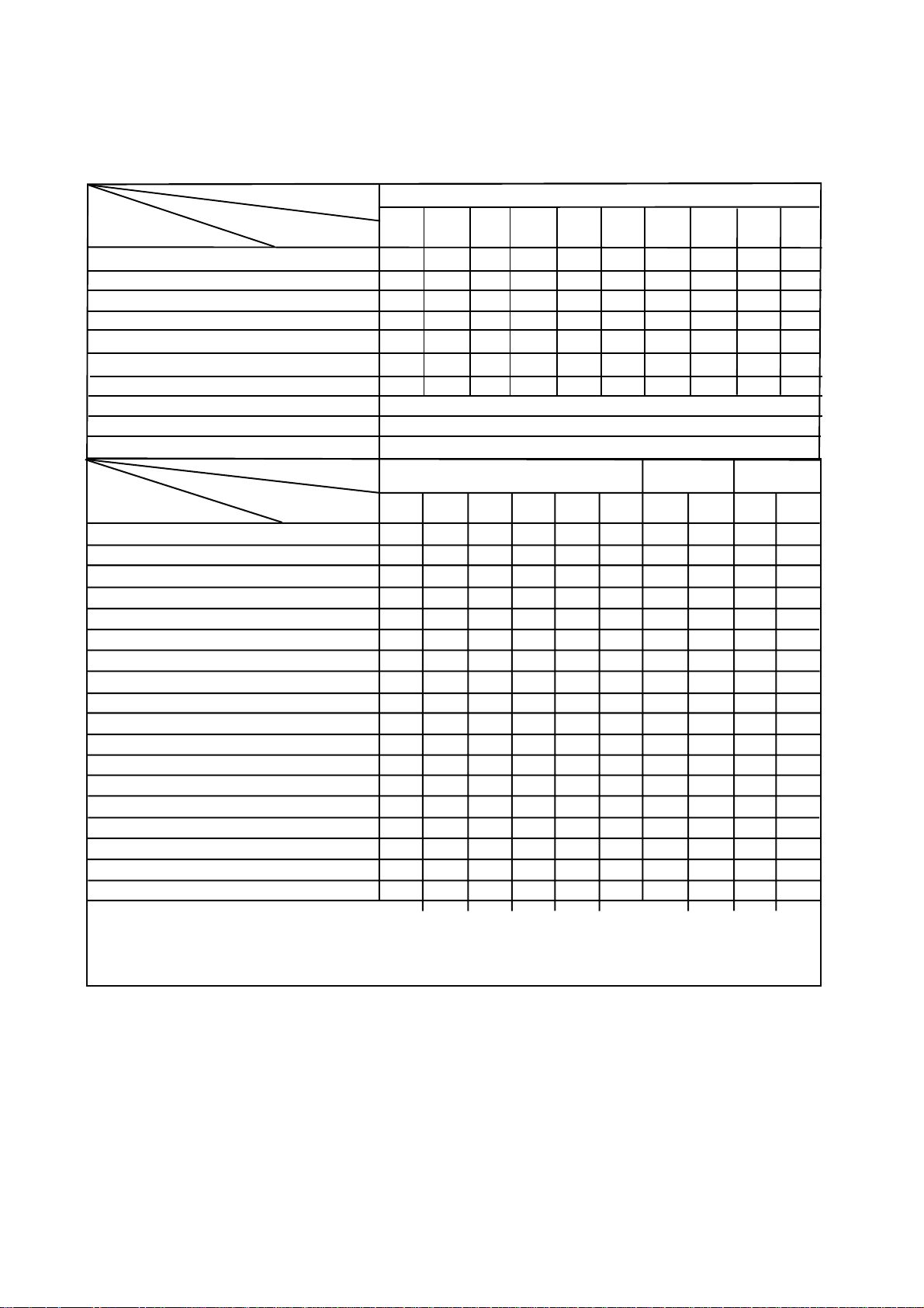
VERSION VARIATIONS
1-2
Type /Versions:
Board in used:
Service policy
MAIN BOARD
CD/MCU BOARD
HEADPHONE JACK BOARD
DISPLAY BOARD
AC POWER BOARD
KEY BOARD
TUNER BOARD
Type /Versions: MCM277
Features
in used:
Line Out
Video Out
Surround Out
Subwoofer Out
Power Booster Out
Digital Out
Digital in
Matrix Surround
Dolby Pro Logic (DPL)
Incredible Surround
Karaoke Features
Voltage Selector
ECO Power Standby (LCD Display Off) x x
USB Direct
Feature diffrence
/05 /12
C
M
C
C
C
C
M
/05
/12 /98
x x x x
C
M
C
C
C
C
M
xxSDR
xxsweN
xxxniRDC/nixuA
x
MCM277
/55
89/16/85/
C
C
C
C
C
C
M
* TIPS : C -- Component Lever Repair.
M -- Module Lever Repair
-- Used
x
Page 3

SPECIFICATIONS
GENERAL:
Mains voltage : 127/240V -15%+10% Switchable for /98
120V ± 10% for /37
230V ± 10% for /05/12
Mains frequency : 50/60Hz
Clock accuracy : < 4 seconds per day
Dimension centre unit :194(W)x269(H)x90(D) (mm)
1-3
Dynamic Bass Boost (DBB) : ON / OFF
Input sensitivity
Aux in (at 1kHz) : 500mV at 600 Ω
USB : Host
Output sensitivity
Headphone output at 32 Ω : 10mW ± 2dB (Max. vol.)
Power consumption
Active : 20W
Standby : < 5.5W (DEMO mode)
ECO Power Standby : < 0.5W for /05/12/37
TUNER:
FM
Tuning range : 87.5-108MHz
Grid : 50kHz for /98/12/05
100kHz for /98/55/37
IF frequency : 10.7MHz ± 20kHz
Aerial input : 75 Ω coaxial /05/12/98
300 Ω for /37
Sensitivity at 26dB S/N : < 22µf
Selectivity at 300kHz bandwidth : > 25dB
Image rejection : > 25dB [> 75dB]
IF rejection : > 60B [> 80dB]
Distortion at RF=1mV, dev. 75kHz : < 3%
-3dB Limiting point : < 23.5dBf
Crosstalk at RF=1mV, dev. 40kHz : > 18dB
COMPACT DISC:
Frequency response within ± 3dB : 125Hz - 16kHz
Output level (in Vrms) : 500mV, Z
= 100Ω
out
Signal/Noise ratio (unw.) : > 65dB
Signal/Noise ratio (A-weighted) : > 76dB
Distortion at 1kHz : < 0.02%
Channel unbalance (-40dB) : < ±2dB
Channel separation at 1kHz : > 30dB
Emphasis : 15/50 µS (switched
automatically by CD10)
THD Noise(1kHz,500mW) : < 1.0%
Volume attenuation(1kHz) : > 60dB
MP3 CD WMA:
MP3 : MPEG 1 (ISO/IEC 11172-3)
Layer3
MP3-CD Bit Rate : 8-320 kbps
WMA-CD Bit Rate
: 64-192 kbps
Sampling Rate : 8, 11.025, 12, 16, 22.05,
24, 32, 44.1, 48 kHz
Format
: ISO9660, Joliet,UDF
ID3 : V1 tag/V2 2.0/V2 3.0
Language Support : English
MW
Tuning range : 531-1602kHz for /05/12/55/98
530-1700kHz for /37/98
Grid : 9kHz for /05/12/55/98
10kHz for /37/98
IF frequency : 450kHz ± 1kHz
Aerial input : Frame aerial 18.1µH
Sensitivity at 26dB S/N : < 4.4mV/M
Selectivity at 300kHz bandwidth : > 18dB
IF rejection : > 45dB
Image rejection : > 28dB
Distortion at RF=50mV, M=80% : < 5%
AMPLIFIER:
Output power
L & R : 2 x 5.0W (4Ω, 1kHz, 10% THD)
:2 x 4.5W (4Ω, 1kHz, 10% THD) /98
:2 x 4.5W (FTC Power, 4Ω, 1kHz, 10% THD
63Hz-12.5kHz) /37
Frequency response within -3dB : 50Hz-16kHz
Digital Sound Control (DSC) : Jazz / Rock / Pop / Classic
[....] Values indicated are for /05/12 only.
Page 4

MEASUREMENT SETUP
Tuner FM
1-4
Bandpass
LF Voltmeter
e.g. PM2534
RF Generator
e.g. PM5326
DUT
250Hz-15kHz
e.g. 7122 707 48001
Ri=50
S/N and distortion meter
e.g. Sound Technology ST1700B
Use a bandpass filter to eliminate hum (50Hz, 100Hz) and disturbance from the pilottone (19kHz, 38kHz).
Tuner AM (MW,LW )
RF Generator
e.g. PM5326
Ri=50
DUT
Frame aerial
e.g. 7122 707 89001
Bandpass
250Hz-15kHz
e.g. 7122 707 48001
LF Voltmeter
e.g. PM2534
S/N and distortion meter
e.g. Sound Technology ST1700B
To avoid atmospheric interference all AM-measurements have to be carried out in a Faraday´s cage.
Use a bandpass filter (or at least a high pass filter with 250Hz) to eliminate hum (50Hz, 100Hz).
CD
Use Audio Signal Disc
DUT
L
R
SBC429 4822 397 30184
S/N and distortion meter
e.g. Sound Technology ST1700B
LEVEL METER
e.g. Sennheiser UPM550
with FF-filter
(replaces test disc 3)
Page 5

SERVICE AIDS
1-5
GB
All ICs and many other semi-conductors are
susceptible to electrostatic discharges (ESD).
Careless handling during repair can reduce life
drastically.
When repairing, make sure that you are
connected with the same potential as the mass
of the set via a wrist wrap with resistance.
Keep components and tools also at this
potential.
WARNING
GB
Safety regulations require that the set be restored to its original
condition and that parts which are identical with those specified,
be used
Safety components are marked by the symbol
!
.
ESD
CLASS 1
LASER PRODUCT
Lead free
Page 6

INSTRUCTIONS ON CD PLAYABILITY
Customer complaint
"CD related problem"
Set remains closed!
check playability
1
1-6
playability
ok ?
Y
Play a CD
for at least 10 minutes
check playability
playability
ok ?
Y
N
"fast" lens cleaning
check playability
playability
ok ?
N
3
N
Y
For flap loaders (= access to CD drive possible)
cleaning method
4 is recommended
add Info for customer
"SET OK"
2
return set
1 - 4 For description - see following pages
Exchange CDM
Page 7
INSTRUCTIONS ON CD PLAYABILITY
1-7
1
PLAYABILITY CHECK
For sets which are compatible with CD-RW discs
use CD-RW Printed Audio Disc....................7104 099 96611
TR 3 (Fingerprint)
TR 8 (600µ Black dot) maximum at 01:00
• playback of these two tracks without audible disturbance
playing time for: Fingerprint
Black dot from 00:50 to 01:10
• jump forward/backward (search) within a reasonable time
For all other sets
use CD-DA SBC 444A..................................4822 397 30245
TR 14 (600µ Black dot) maximum at 01:15
TR 19 (Fingerprint)
TR 10 (1000µ wedge)
• playback of all these tracks without audible disturbance
playing time for: 1000µ wedge 10seconds
Fingerprint 10seconds
Black dot from 01:05 to 01:25
• jump forward/backward (search) within a reasonable time
10seconds
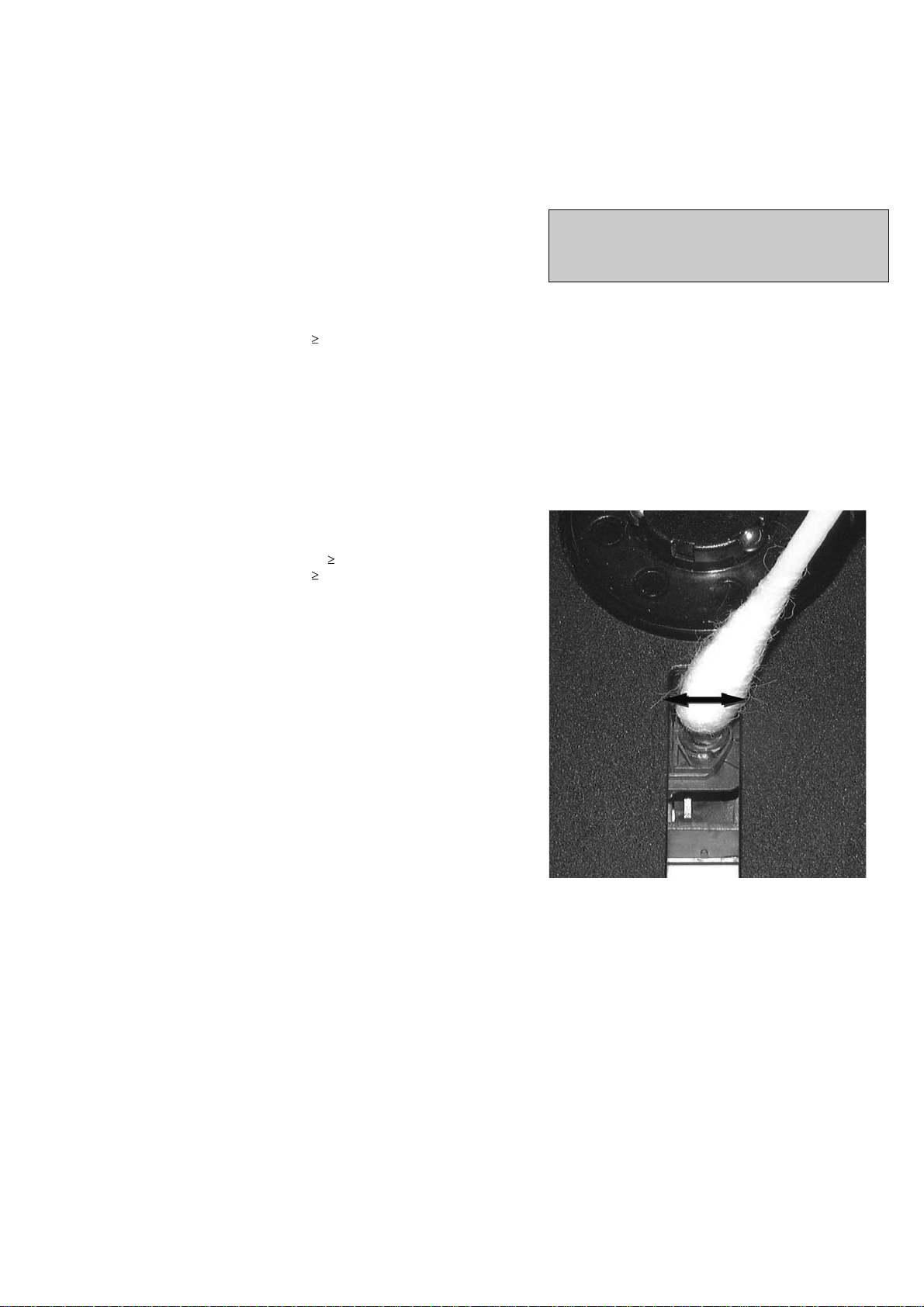
4
LIQUID LENS CLEANING
Before touching the lens it is advised to clean the
surface of the lens by blowing clean air over it.
This to avoid that little particles make scratches on
the lens.
Because the material of the lens is synthetic and coated
with a special anti-reflectivity layer, cleaning must be done
with a non-aggressive cleaning fluid. It is advised to use
“Cleaning Solvent
The actuator is a very precise mechanical component and
may not be damaged in order to guarantee its full function.
Clean the lens gently (don’t press too hard) with a soft and
clean cotton bud moistened with the special lens cleaner.
The direction of cleaning must be in the way as indicated in
the picture below.
2
CUSTOMER INFORMATION
It is proposed to add an addendum sheet to the set which
informs the customer that the set has been checked
carefully - but no fault was found.
The problem was obviously caused by a scratched, dirty or
copy-protected CD. In case problems remain, the customer
is requested to contact the workshop directly.
The lens cleaning (method 3) should be mentioned in the
addendum sheet.
The final wording in national language as well as the printing
is under responsibility of the Regional Service Organizations.
Page 8
PREPARATIONS AND CONTROLS
Preparation
Setting the clock
After connecting MCM275 to the power supply,
set the clock first.
1
Press and hold STANDBY-ON/ ECO
POWER to switch the set to Standby mode
The display shows the set time
-- --:-- -- flashes by default if you have not set
the clock
2
In the standby mode, press and hold DISPLAY/
CLOCK on the remote control
SET CLOCK scrolls on the display
24 HR or 12 HR appears for the initial
clock setting. To select 24-hour clock or
12-hour clock,
On the remote control, press VOLUME +/-
once or more (or turn VOLUME on the
set)
On the remote control, press DISPLAY/
CLOCK to confirm
The hours digits star t flashing
3
Hold down or press VOLUME +/- repeatedly
to set the hours (or turn VOLUME on the
set)
4
Press DISPLAY/CLOCK to confirm
The minutes digits start flashing
5
Hold down or press VOLUME +/- repeatedly
to set the minutes (or turn VOLUME on the
set)
6
Press DISPLAY/CLOCK to confirm
– To exit without storing the clock setting press
STOP 9
Helpful hints:
– The clock setting will be erased when the system
is disconnected from the power supply.
– The set will exit from the clock setting mode if
no button is pressed within 90 seconds.
–To set the clock automatically by using a time
signal which is broadcast together with the RDS
signal see chapter RDS: Automatic clock
setting via RDS.
USB
/
Using the remote control
IMPORTANT!
– Remove the
protective plastic tab
before using the
remote control.
– Always point the
remote control directly
towards IR area.
Notes for remote control:
– First select the source you wish to
control by pressing one of the source select
keys on the remote control (for example
CD, TUNER).
–Then select the desired function (for
example
ÉÅ
,
í
,
ë
).
To replace the remote controls’
battery
C
R
2
0
2
5
L
I
T
H
I
U
M
2
3
1
CAUTION!
– Remove the battery if it is exhausted
or will not be used for a long time.
– Batteries contain chemical substances,
so they should be disposed of properly.
1
Press and hold 1 as indicated.
2
Simultaneously, pull the battery tray at 4.
3
Remove the old battery and put a new CR2025
battery in place.
4
Put back the battery tray.
1
2
3
!
9
@
0
#
7
6
5
4
8
%
$
1-8
Page 9
PREPARATIONS AND CONTROLS
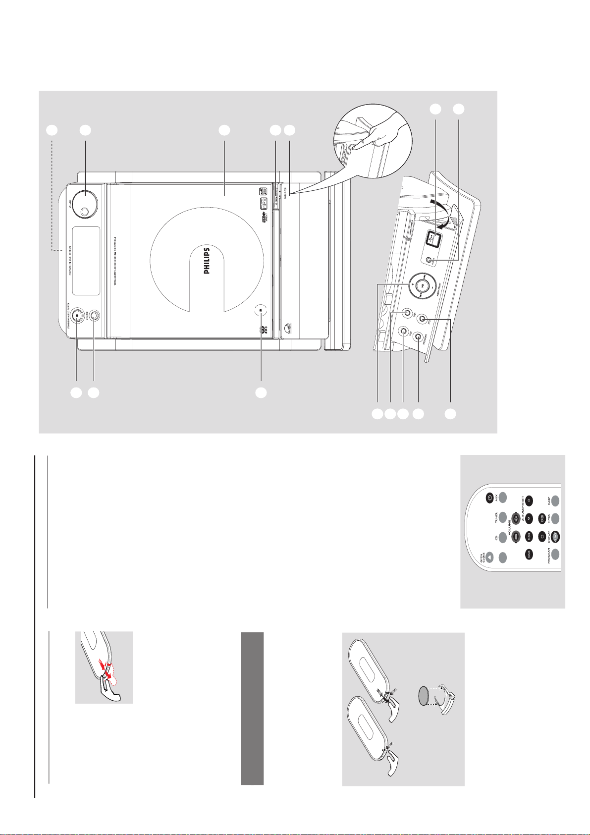
Controls
1
STANDBY-ON/ ECO POWER
– press briefly to switch the set on or off (standby/
ECO POWER);
– In standby or Eco Power mode: press and
hold to toggle between Standby and ECO
POWER mode (power-saving mode)
– Red indicator: lights up red when the set is
switched to ECO POWER mode
2
SOURCE
–selects sound source CD, USB, TUNER or
AUX
– In standby or Eco Power mode: switches the
set on and selects sound source CD, USB,
TUNER or AUX
3
IR
–sensor for the infrared remote control
Helpful hints: Always point the remote control
towards this sensor.
4
PUSH OPEN
– push to unfold or fold the control panel
5
CD OPEN • CLOSE 0
– opens/closes the CD door
6
CD door
7
VOLUME
–adjusts the volume level
– Clock/Timer: adjusts the hours and minutes
8
nn
nn
n
– 3.5 mm headphone socket
Helpful hints:
– Adjust the volume to a moderate level
before you plug in the headphones.
– Connecting headphones will switch off the
speakers.
9
ALBUM/ PRESET + /-
– CD/USB: selects albums (for MP3/WMA only)
– TUNER: selects a preset radio station
4 / ¢
– CD/USB: skips or searches CD tracks/titles
backwards/forwards
– Tun e r : tunes to radio stations
6
– CD/USB: starts or pauses playback
0
DBB (Dynamic Bass Boost)
– turns the bass enhancement on/off
!
DSC (Digital Sound Control)
–selects predefined sound settings: ROCK,
JAZZ, POP, CLASSIC
@
PROGRAM
– CD/USB: programs tracks
– Tuner: programs preset radio stations
#
STOP
– CD/USB: stops playback; erase a program
$
AUX-IN
– connects to the AUDIO OUT jack on the
external appliance
%
– jack for the external USB mass storage device
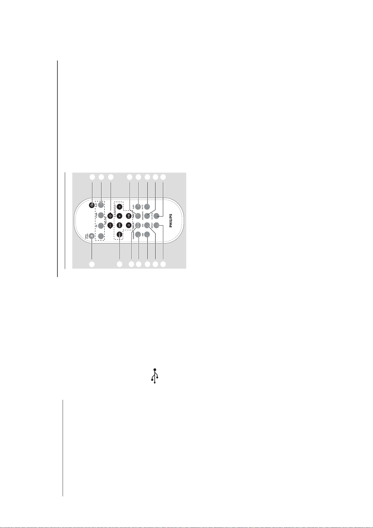
Remote control
7
8
1
%
$
@
!
9
0
#
2
4
5
6
3
USB
/
AUX
– selects the audio input from an additional
connected appliance
– In standby or Eco Power mode:: switches the
set on and selects the audio input from an
additional connected appliance
3
VOLUME +/-
– adjusts the volume level
– Clock/Timer: adjusts the hours and minutes
4
TIMER
–displays the timer setting
– switches the timer on/off
– enters the timer setting mode (press and hold
for more than 2 seconds)
5
SLEEP
– set the sleep timer
6
MUTE
– switches the sound off temporarily
7
RDS/NEWS
– Tun er : selects RDS (Radio Data System)
information
– CD/USB/AUX: activates/deactivates news
8
SHUFFLE
– selects random playback
9
REPEAT
– selects continuous playback
0
DSC (Digital Sound Control)
–selects predefined sound settings: ROCK,
JAZZ, POP, CLASSIC
!
DBB (Dynamic Bass Boost)
– turns the bass enhancement on/off
@
PROGRAM
– CD/USB: programs tracks
– Tun e r: programs preset radio stations
#
DISPLAY/CLOCK
– Clock: - displays the set time
- In standby mode: enters the clock
setting mode (press and hold for more
than 2 seconds)
– TUNER/Audio CD: switches between clock
display and playback
display
– MP3/WMA files: displays disc information
during playback
Notes for remote control:
– First select the source you wish to
control by pressing one of the source select
keys on the remote control (for example
CD, TUNER).
–Then select the desired function (for
example
ÉÅ
,
í
,
ë
).
1
BB
BB
B
–press briefly to switch the set on or off (standby/
ECO POWER);
– In standby or Eco Power mode: press and
hold to toggle between Standby and ECO
POWER mode (power-saving mode)
2
Source buttons
USB
–selects USB source
– In standby or Eco Power mode:: switches the
set on and selects USB source.
CD
–selects CD source
– In standby or Eco Power mode:: switches the
set on and selects CD source.
TUNER
– selects TUNER source and toggles between the
wavebands: FM and MW
– In standby or Eco Power mode:: switches the
set on and selects TUNER source
Controls
1-9
Page 10
CONTROLS & INSTALLATIONS
$
4 / ¢
– CD/USB: skips or searches CD tracks
backwards/forwards
– Tuner: tunes to radio stations
ALBUM/ PRESET 3 / 4
– CD/USB: selects the next/previous album (for
MP3/WMA only)
– TUNER: selects a preset radio station
ÉÅ
– CD/USB: starts or pauses playback
9
– CD/USB: stops playback; erase a program
%
OPEN • CLOSEç
– opens/closes the CD door
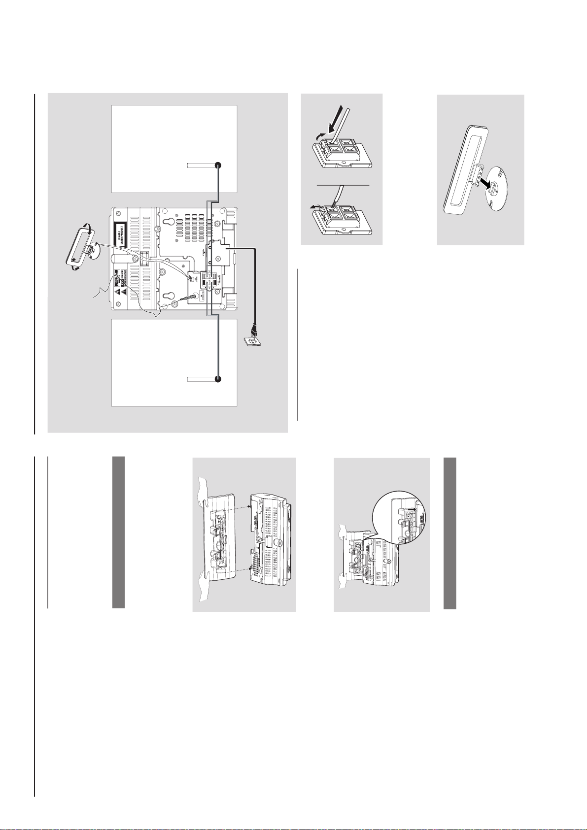
Controls Installation
Placing MCM275
With the detachable stand and by-packed wall
mounting kit , MCM275 allows you to place it in
two ways: on desktops with stand or on
walls without stand.
Mounting stand onto the set
MCM275 is equipped with a stand. To mount
the stand onto the set,
1
Put MCM275 on a flat and firm surface, rear side
facing up
2
As shown, align the stand to the slots at set’s
bottom, 4 FRONT facing down
P
RE
SS
FR
O
NT
FRONT
P
R
E
SS
3
Push the stand down into the slots
When the stand is in place, you will hear a
click
See Appendix: How to mount your
MCM275 onto walls to learn more about
wall mounting.
Mounting MCM275 onto walls
Installation
MW loop
antenna
Speaker
(left)
Speaker
(right)
FM wire
antenna
AC power cord
Rear connections
Warning:
– Never make or change connections with
the mains supply switched on.
– Install your set near the AC outlet and
where the AC power plug can be reached
easily.
A
Speaker connections
Use the supplied speakers only. Using other
speakers can damage the set or the sound
quality will be negatively affected.
Connect the cable of the left speaker to LEFT
(red and black) and the cable of the right
speaker to RIGHT (red and black) as follows:
a. Press the clip of the red terminal and fully
insert the stripped portion of the colored (or
marked) speaker cable into the socket, then
release the clip
b. Press the clip of the black terminal and fully
insert the stripped portion of the black (or
unmarked) speaker cable into the socket, then
release the clip
B
Antenna connections
MW antenna
1
Assemble the loop antenna as shown:
1-10
Page 11

CONTROLS & INSTALLATIONS
Installation
2
Fit the plug of the loop antenna to AM (MW)
ANTENNA as shown below
3
Adjust the position of the antenna for optimal
reception (as far away as possible from the TV,
VCR or other radiation sources)
FM antenna
The wire antenna supplied can only be used to
receive nearby stations. For better reception we
recommend using a cable antenna system or an
outdoor antenna.
1
Extend the wire antenna and fit it to FM
ANTENNA as shown below
AM
ANTENNA
Or
Insert the loop antenna into the slot on the set
Note: If you are using a cable antenna system or
an outdoor antenna, fit the antenna plug, instead of
the wire antenna, to FM ANTENNA .
By connecting a USB mass storage device
(including USB flash memory, USB flash players
or memory cards) to the Hi-Fi system, you can
enjoy the device’s stored music through the
powerful speakers of Hi-Fi system.
1
Check you have unfolded the control panel
2
Insert the USB device’s USB plug into the socket
on the set ‘s foldable control panel
2
Move the antenna in different positions for
optimal reception (as far away as possible from
the TV, VCR or other radiation sources)
3
Fix the antenna’s end to the wall
Connecting an additional
appliance
Connecting a USB device or memory
card
or
for the devices with USB cable:
a. Insert one plug of the USB cable (not
supplied) to the socket
on the set ‘s
foldable control panel
b. Insert the other plug of the USB cable to the
USB output terminal of the USB device
or
for the memory
card:
a. Insert the memory card into a card reader
(not supplied)
b. Use a USB cable (not supplied) to connect
the card reader to the socket
on the set ‘s foldable control panel
Installation
Using AC power
1
Make sure all the connections have been made
before switching on the power supply
2
Connect the AC power cord to the wall socket.
This switches on the power supply
When MCM275 is switched to standby, it is still
consuming some power. To disconnect the
system from the power supply completely,
remove the power plug from the wall
socket.
The type plate is located on the rear of the
set.
For users in the U.K.: please follow the
instructions.
Warning!
To avoid overheating of the system, a safety
circuit has been built in. Therefore, your
system may switch to Standby mode
automatically under extreme conditions. If
this happens, let the system cool down
before reusing it (not available for all versions).
This product complies with the radio
interference requirements of the European
Community.
CAUTION
Visible and invisible laser radiation. If the
cover is open, do not look at the beam.
High voltage! Do not open. You run the risk
of getting an electric shock.
The machine does not contain any user-
serviceable parts.
Modification of the product could result in
hazardous radiation of EMC or other
unsafe operation.
4
Select AUX mode on the set
Helpful hints:
–Always refer to the owner’s manual of other
equipment for complete connection.
Connecting a non-USB device
It is possible to use an additional appliance, e.g.
TV, VCR or CD recorder with the set. On
MCM275, you can playback music from an
external source.
1
Follow the Step 1 under Connecting a USB
device or memory card
2
Insert one plug of the audio cable (not supplied)
to the socket AUX IN on the set ‘s foldable
control panel
3
Connect the other end of the audio cable to the
AUDIO OUT terminal of the additional
appliance
1-11
Page 12

English
Troubleshooting
WARNING
Under no circumstances should you try to repair the system yourself, as this will invalidate the
warranty. Do not open the system as there is a risk of electric shock.
If a fault occurs, first check the points listed below before taking the system for repair. If you
are unable to remedy a problem by following these hints, consult your dealer or Philips for
help.
“NO DISC” is displayed.
Some files on the USB device are not
displayed.
Radio reception is poor.
The system does not react when buttons
are pressed.
Sound cannot be heard or is of poor
quality.
The left and right sound outputs are
reversed.
Problem
Solution
Insert a disc.
Wait until the moisture condensation at the lens
has cleared.
Replace or clean the disc, see “Maintenance”.
Use a finalised CD-RW or a correct MP3/WMA
-CD format disc.
Check if the number of folders exceeds 99 or
the number of titles exceeds 999
If the signal is too weak, adjust the antenna or
connect an external antenna for better
reception.
Increase the distance between the Micro HiFi
System and your TV or VCR.
Remove and reconnect the AC power plug and
switch on the system again.
Adjust the volume.
Disconnect the headphones.
Check that the speakers are connected correctly.
Check if the stripped speaker wire is clamped.
Make sure the MP3-CD was recorded within
32~256 kbps bit rate with sampling frequencies
at 48 kHz, 44.1 kHz or 32 kHz.
Check the speaker connections and location.
The remote control does not function
properly.
The timer is not working.
The Clock/Timer setting is erased.
Select the source (CD or TUNER, for example)
before pressing the function button (ÉÅ,í,
ë).
Reduce the distance between the remote
control and the system.
Insert the batter y with its polarities
(+/– signs) aligned as indicated.
Replace the battery.
Point the remote control directly toward
IR sensor on the front of the system.
Check the set is switched off
Set the clock correctly.
Press TIMER to switch on the timer.
Power has been interrupted or the power cord
has been disconnected. Reset the clock/timer.
Troubleshooting
TROUBLESHOOTING
1-12
Page 13

DISMANTLING INSTRUCTIONS
2-1 2-1
Dismantling the Rear Portion and PCBs
1) Press the 2 juts and pull out the Stand as shown in figure
1.
Figure 1
Figure 2
Dismantling the Rear Portion and PCBs
5) Loosen 2 screws E to remove the Bracket Jack Board as
shown in Figure 4.
6) Loosen 3 screws F to remove the Main Board as shown
in figure 5.
Figure 4
2) Loosen 5 screws A and 6 screws B to remove the Rear
Cabinet as shown in figure 2.
3) Loosen 3 screws C to remove the SP & ANT Jack Board
as shown in figure 3.
4) Loosen 5 screws D to remove the Power Module as
shown in figure 3.
Figure 5
Dismantling of the Display Lens & the Volume knob
1) Use a flat head screw driver to give a push in the direction
as shown in figure 6.
2) Place two small screw drivers in between the front cabinet
& knob to give more leverage in pulling out the Volume
Knob as shown in figure 7.
Figure 3
Figure 7
Figure 6
Page 14
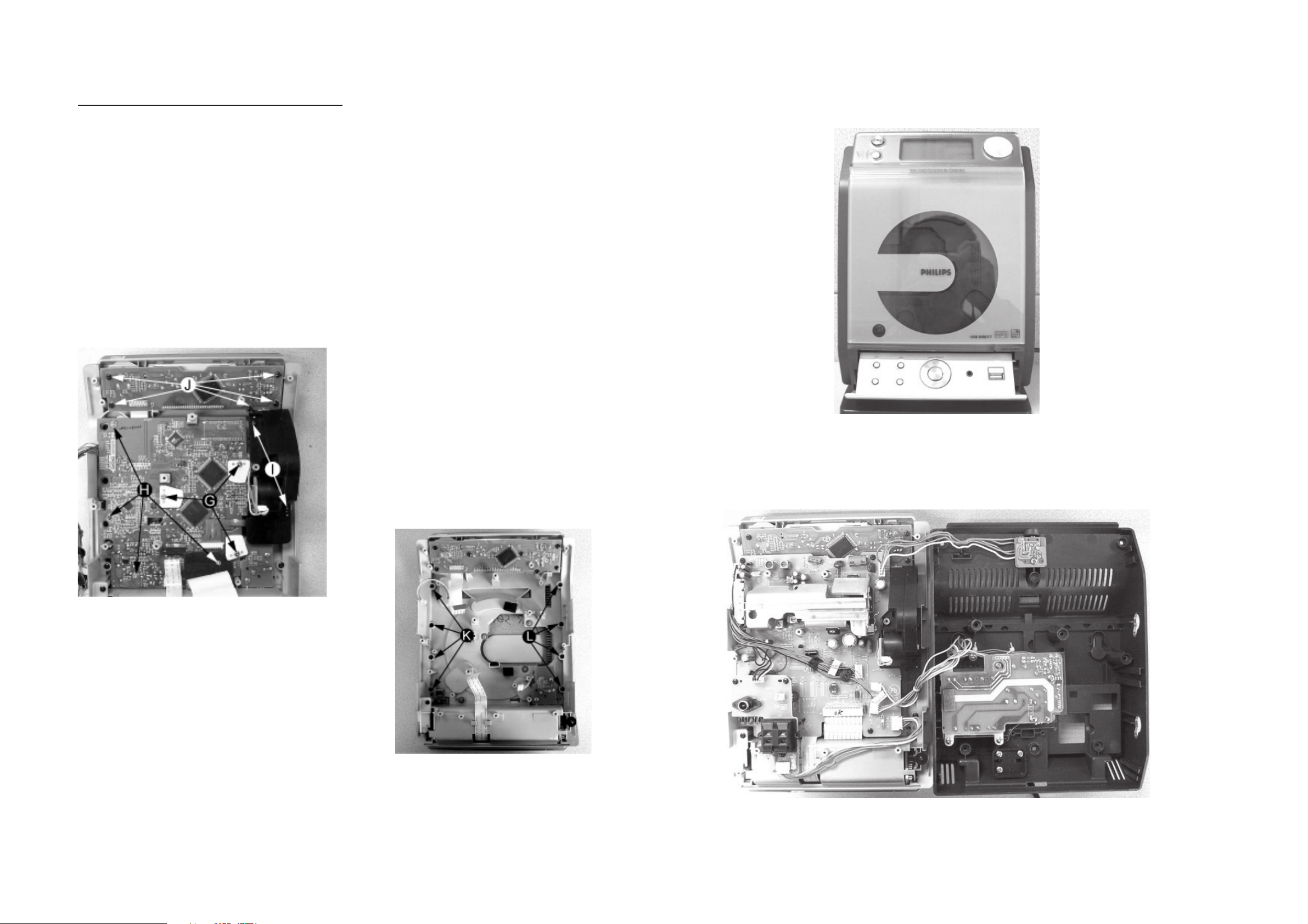
Dismantling of the CD Module & CD Door Carrier
1) Loosen 5 screws J mounting the Key Board to the Front
Cabinet to remove the Key Board as shown in figure 8.
2) Loosen 4 screws H and 3 screws G to CD Module as
shown in figure 8.
3) Loosen 2 screws I to remove the Servo Motor Mechanism
as shown in figure 8.
2-2
2-2
Service pos A
Figure 8
4) Loosen 4 screws K to remove the Right CD Door Carrier
and 4 screws L to remove the Left CD Door Carrier as
shown in figure 9.
Service pos B
Figure 9
Note: After re-assembly, it is very important to ensure all
wires are routed properly to ensure that they do not
touch/obstruct all moving parts.
Page 15

SERVICE TEST PROGRAM
3-1
3-1
KEY
TEST
Button pressed?
Button pressed?
NEXT
Y
Display shows
Table 1
9
Y
To enter Service
Testprogram hold
PLAY & Door Open/Close
buttons
depressed while
plugging mainscord in.
Display shows the
MCU version
"MCU-V
yy"
(Main menu)
N
N
Figure 1
Door switch is ignored → CD door can be opened.
*
V refers to Version
yy refers to Software version number of the uProcessor
(counting up from 01 to 99)
DISPLAY
TEST
PREV
Button pressed?
Y
Display shows Figure 1
All display flags on.
PREV
Button pressed?
Y
Display shows alternate
segment display from SEG0
to SEG64.
ADC
TEST
N
N
DBB
Button pressed?
Y
Display shows "ADC0 Value"
for ADC0
(Input Line - For key scanning)
DBB
Button pressed?
Y
Display shows "ADC1 Value"
for ADC1
(Input Line - ioNTC Heat
detection for transformer)
N
N
Various
other Tests
TEST
EEPROM CLEAR A test pattern will be sent to the EEPROM.
LEAVE SERVICE
TEST PROGRAM
Activated with
PROGRAM
9
to Exit
Disconnect
mains cord
ACTION
"EEP CLR" is displayed while the erase processing.
Caution! All presets from the customer will be lost!!
Key test table
KeyNr Set key KeyNr Set key KeyNr Set key
0 CD 10 RDS 20 PROGRAM
1 AUX 11
2 TUNER 12 CLOCK/DISP
LAY
3 SOURCE 13 ALBUM + SLEEP
4
STANDBY/ON
5
OPEN/CLOSE
6
VOLUME DOWN
14 ALBUM - TIMER
15
SKIP PREV 25 DBB
16 SKIP NEXT 26 DSC
7 VOLUME UP 17 NULL 27 MUTE
8 NULL 18 NULL 28 USB
9 NULL 19 REPEAT
Table 1
21 SHUFFLE
22 NULL
23
24
PREV
Button pressed?
Y
No Display shows
9
Button pressed?
Y
ADC Test is used for checking the
ADC inputs to the microprocessor.
The display shows an ADC value
between 0 and 255 for an input
signal between 0 and 5V.
N
N
DBB
Button pressed?
Y
Display shows "ADC2 Value"
for ADC2
(Input Line - Rotary volume)
DBB
Button pressed?
Y
Display shows "ADC3 Value"
for ADC3
(Input Line - Door switch status)
DBB
Button pressed?
Y
Display shows "ADC4 Value"
for ADC4
(Input Line - Version detection)
9
Button pressed?
Y
N
N
N
N
Page 16
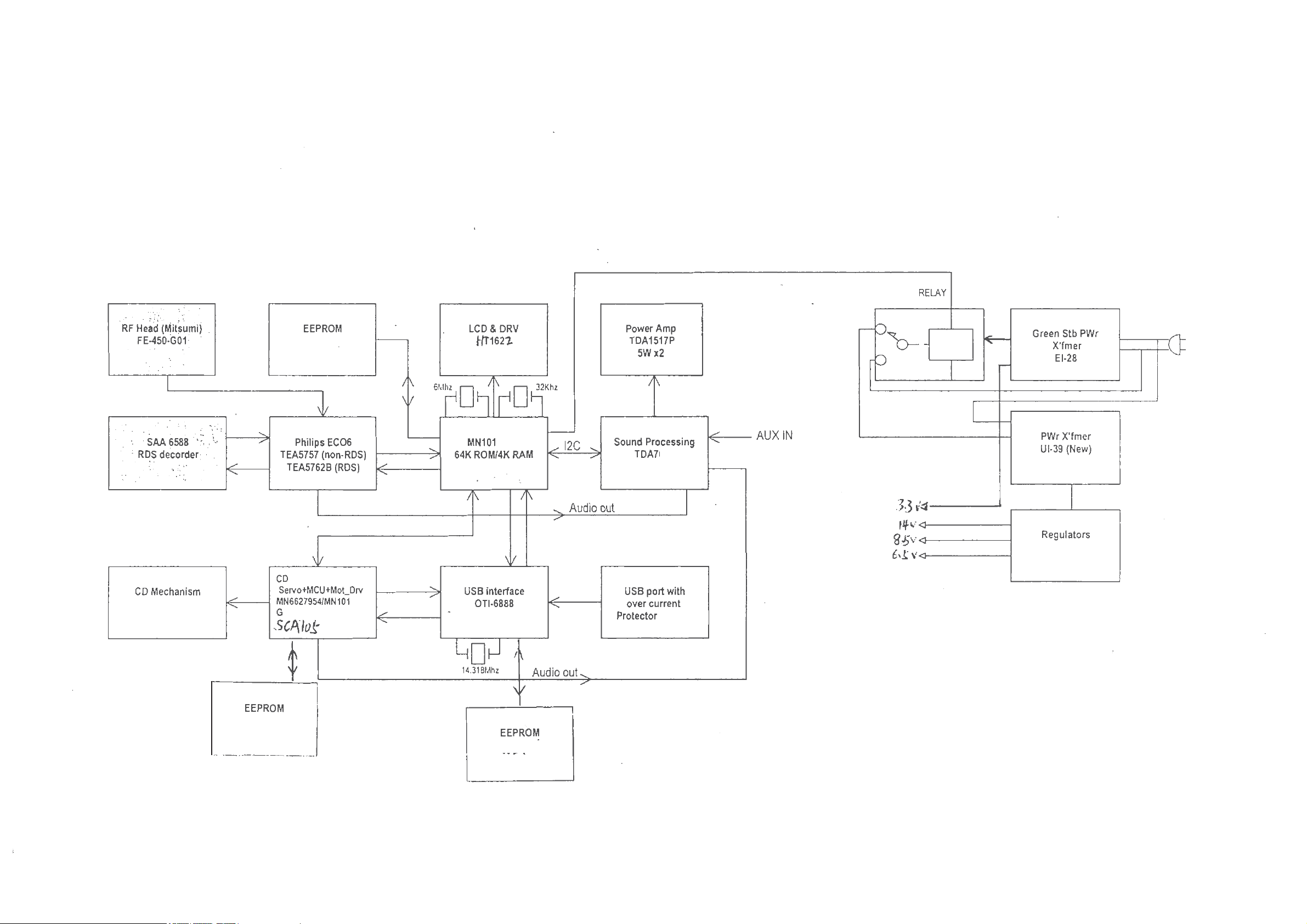
SET BLOCK DIAGRAM
4-1 4-1
BR24L02F-WE2
IC104
IC701
IC801
UR11
DAYANG M93BGP-BF
IC100
BR24L02F-WE2
IC504
IC401
IC501
IC102
CF91D
E01J
IC103
IC300
W27C512-45Z
IC302
468D
IC601
AP34063A
IC301
Page 17

SET WIRING DIAGRAM
5-1
5-1
Page 18
6-1
6-1
BLOCK DIAGRAM - RDS/RBDS PRE-PROCESSOR
SAA6588T
BLOCK DIAGRAM
multi-path
data
available
pause
output
output
C-BUS
2
I
MAIN BOARD
TABLE OF CONTENTS
Internal IC Diagram ............................................... 6-1 to 6-5
Main Board(5757) Layout Top View ................................ 6-6
Main Board(5757) Layout Bottom View .......................... 6-7
Circuit Diagram - Main Board(5757) ............................... 6-8
Main Board(5762) Layout Top View ................................ 6-9
Main Board(5762) Layout Bottom View ........................ 6-10
Circuit Diagram - Main Board(5762) ............................. 6-11
HP Jack Board ............................................................... 6-12
Electrical Parts List ........................................................ 6-13
DAVN
C9
100 nF
DDD
VNICTUOCS
5 V
C10
560 pF
8
71918
RDS/RDBS
RDS/RDBS
CLOCKED
57 kHz
16
MPX
330 pF
C1
multiplex
PSWN
11
DECODER
DEMODULATOR
COMPARATOR
8th ORDER
BAND-PASS
0.47 嘕F
C2
audio
input
MPTH
2
SAA6588
10
k"
R2
0.47 嘕F
C3
inputs
10
k"
R3
REGISTER
INTERFACE
4
DETECTOR
SIGNAL QUALITY
DETECTOR
MULTI-PATH
PAUSE
DETECTOR
13
AFIN
SDA
SCL
9
10
12
MAD
SSD
V
C-BUS SLAVE
2
I
5
4
OSCILLATOR
TEST
POWER
20
14
DDA
LVI N
V
C11
2.2 nF
level
input
6
TRANSCEIVER
4
AND CLOCK
5
1
3
CONTROL
1715
SUPPLY
AND RESET
C8
100 nF
5 V
OSCO
OSCI
TCON MRO
ref
V
SSA
V
R1
C7
R4
C6
2.2 嘕F
1 k"
Q1
470
100
k"
nF
MGK535
C5
MHz
n h4.332
C4
82 pF
n = 1 to 4
47 pF
Page 19
6-2 6-2
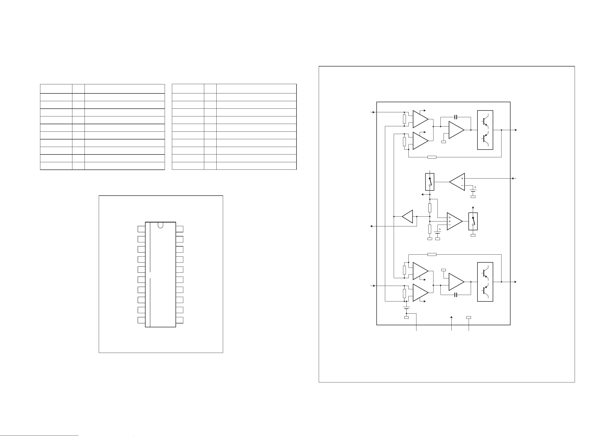
BLOCK DIAGRAM
mute/stand-by
switch input
MLC351
output 1
15 k
15 k
x 1
VA
stand-by
switch
V
P
mute
switch
stand-by
reference
voltage
18 k
18 k
2
k
60
k
mute switch
C
m
power stage
4
8
mute switch
VA
VA
C
m
2
k
60
k
power stage
6
275
SGND
signal
ground
PGND
output 2
non-inverting
input 1
non-inverting
input 2
9
supply voltage
ripple rejection
output
3
1
TDA1517
mute
reference
voltage
input
reference
voltage
V
P
power
ground
(substrate)
PIN DESCRIPTION - RDS/RBDS PRE-PROCESSOR
SAA6588T
PINNING
SYMBOL PIN DESCRIPTION
MRO 1 mXOWLSDWKUHFWL¿HURXWSXW
MPTH 2 mXOWLSDWKGHWHFWRURXWSXW
TCON 3 WHVWFRQWUROLQSXWSLQ
OSCO 4 RVFLOODWRURXWSXW
OSCI 5 RVFLOODWRULQSXW
V
V
SSD
DDD
6 digital gURXQG0V)
7 digital supply vROWDJH5V)
DAVN 8 data availabOHRXWSXWDFWLve LOW)
2
SDA 9 I
SCL 10 I
C-bus serial data I/O
2
C-bus serLDOFORcNLQSXW
SYMBOL PIN DESCRIPTION
PSWN 11 pause sZLWFKRXWSXWDFWLve LOW)
MAD 12 slavHDGGUHVV/6%LQSXW
AFIN 13 DXGLRVLJQDOLQSXW
V
V
DDA
SSA
14 DQDORJVXSSO\vROWDJH5V)
15 DQDORJgURXQG0V)
MPX 16 multiple[LQSXWVLJQDO
V
ref
17 refHUHQFHvROWDJHRXWSXW
SCOUT 18 EDQGSDVV¿OWHURXWSXW
CIN 19 FRPSDrDWRULQSXW
LV IN 20 l ev HOLQSXW
BLOCK DIAGRAM - POWER AMPLIFIER
TDA1517
MRO
OSCI
1
2
3
4
5
MPTH
TCON
OSCO
SAA6588T
V
V
DAVN
SSD
DDD
SDA
SCL
6
7
8
9
10
MGK534
20
19
18
17
16
15
14
13
12
11
LVIN
CIN
SCOUT
V
ref
MPX
V
SSA
V
DDA
AFIN
MAD
PSWN
Page 20
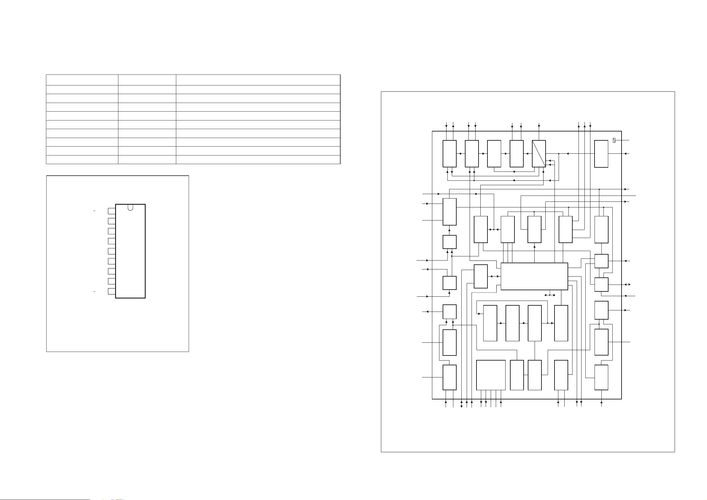
6-3
.This text is here in
BLOCK DIAGRAM
PRESCALER
PROGRAMMABLE
COUNTER
STABILIZER
WINDOW
DETECTOR
LAST-STATION
MEMORY
AM/FM
INDICATOR
IN-LOCK
DETECTOR
FM
DETECTOR
PILOT
DETECTOR
CHARGE
PUMP
MULTIPLEXER
CRYSTAL
OSCILLATOR
SHIFT REGISTER
FM
FRONT-END
FM
OSCILLATOR
FM
IF2
FM
IF1
FM
MIXER
SEQUENTIAL
CIRCUIT
STATUS
REGISTER
AM
FRONT-END
AM
OSCILLATOR
AM
DETECTOR
V/I
CONVERTER
AM
MIXER
AM
IF
AGC
AFC
hard mute
level
PLL
DECODER
MATRIX
SDS
MUTE
up
down
level
RFGND
DATA
BUS-CLOCK
WRITE-ENABLE
FM-RFI
V
STAB(A)
V
STAB(B)
AM-RFI
XTAL
RIPPLE
25
23
1
263031
2
AGC
AM-IFI/O2
AM-MIXERAMOSC
AM-IFI1
6
40 41
36 44
822
32
20
19
13
15
14
9
12
24
16
181739 37 333535
38
4342282729
34
7
21
10
11
4
MO/ST
AFRO
MUTE
AFC
(n)
AFC
(p)
AFC
VCO
LFI
PILFIL
AFLO
stereo
stereo
mono
38 kHz
19 kHz
FM-IFI1 FM-IFI2
FM-IFO1
FM-MIXER
FMOSC
FM-RFO
V
CC1
V
DDD
TEA5757;
TEA5759
FM
AM
DGND
P1
P0
TUNE
RFGND
MPXI
AFO
V
CC2
IFGND FSIFMDEM
MHA111
6-3
PIN DESCRIPTION - POWER AMPLIFIER
TDA1517
PINNING
" 1tupni gnitrevni-non11VNI
V
P
" 2tupni gnitrevni-non92VNI
handbook, halfpage
7supply voltage
INV1
SGND
SVRR
OUT1
PGND
OUT2
V
P
M/SS
INV2
1
2
3
4
5
6
7
8
9
TDA1517
MLC352
1tuptuo41TUO
2tuptuo62TUO
dnuorg langis2DNGS
dnuorg rewop5DNGP
tupni hctiws ybdnats/etum8SS/M
tuptuo noitcejer elppir egatlov ylppus3RRVS
NOITPIRCSEDNIPLOBMYS
BLOCK DIAGRAM - SELF TUNED RADIO
TEA5757
Pin configuration for SOT110-1 and
SOT352-1.
Page 21

k3 lacipyt ecnadepmi tupni( tupni retl¿ cimarec ro TFI141IFI-MA " )
dnuorg FRMF24DNGFR
04 lacipyt ecnadepmi tupni( tupni lairea FRMF34IFR-MF " )
tupni roticapac CGA44CGA
NOITPIRCSEDNIPLOBMYS
Pin configuration.
TEA5757H
TEA5759H
MHA112
1
2
3
4
5
6
7
8
9
10
11
33
32
31
30
29
28
27
26
25
24
23
12
13
14
15
16
17
18
19
20
21
22
44
43
42
41
40
39
38
37
36
35
34
RIPPLE
AM-RFI
FM-RFO
RFGND
FMOSC
AMOSC
V
CC1
TUNE
VCO
AFO
MPXI
FM-IFI2
AFC
P1
P0
WRITE-ENABLE
DATA
BUS-CLOCK
DGND
XTAL
MO/ST
V
DDD
LFI
MUTE
AFLO
AFRO
PILFIL
IFGND
FMDEM
AFC
(n)
AFC
(p)
FSI
V
CC2
AGC
FM-RFI
RFGND
AM-IFI1
AM-MIXER
FM-MIXER
V
STAB(A)
FM-IFI1
AM-IFI/O2
FM-IFO1
V
STAB(B)
6-4
6-4
PIN DESCRIPTION - SELF TUNED RADIO
TEA5757
PINNING
NOITPIRCSEDNIPLOBMYS
tupni roticapac elppir1ELPPIR
tupni FRMA2IFR-MA
dnuorg ot tiucric FRMF denut lellarap3OFR-MF
etartsbus dna dnuorg FR4DNGFR
V
CC1
7supply voltage
tuptuo tnerruc gninut8ENUT
tupni rotallicso dellortnoc egatlov9OCV
tupni retl¿-pool21IFL
tupni etum31ETUM
tupni retl¿ rotceted tolip61LIFLIP
tupni rotanimircsid cimarec81MEDMF
AFC
(n)
AFC
(p)
V
CC2
V
DDD
BUS-CLOCK 27 bus-clock input
WRITE-ENABLE 29 bus write-enable input
V
STAB(B)
AM-IFI/O2 36 input/output to IF-Tank (IFT); output: current source
V
STAB(A)
19 AFC negative output
20 AFC positive output
22 supply voltage for tuning
23 digital supply voltage
tupni latsyrc52LATX
dnuorg latigid62DNGD
tuptuo/tupni atad sub82ATAD
tiucric-CL zHk05423CFA
34 internal stabilized supply voltage (B)
38 internal stabilized supply voltage (A)
rotacidni htgnerts-dle¿12ISF
)0P(trop tuptuo elbammargorp030P
)1P(trop tuptuo elbammargorp131P
FM-MIXER 39 FHUDPLF¿OWHURXWSXWRXWSXWLPSHGDQFHW\SLFDO )
AM-MIXER 40 open-collector output to IFT
dnuorg ot tiucric rotallicso-MF denut lellarap5CSOMF
dnuorg ot tiucric rotallicso-MA denut lellarap6CSOMA
egats XPM dna rotceted ,FI fo dnuorg71DNGFI
tuptuo noitacidni gninut dna oerets/onom42TS/OM
033 lacipyt ecnadepmi tupni( 2tupni FIMF332IFI-MF )
033 lacipyt ecnadepmi tuptuo( 1tuptuo FIMF531OFI-MF )
033 lacipyt ecnadepmi tupni( 1tupni FIMF731IFI-MF )
PIN DESCRIPTION - SELF TUNED RADIO
TEA5757
k5 lacipyt ecnadepmi tuptuo( tuptuo FA MF/MA01OFA )
k051 lacipyt ecnadepmi tupni( tupni redoced oerets11IXPM )
k3.4 lacipyt ecnadepmi tuptuo( tuptuo lennahc tfel41OLFA )
k3.4 lacipyt ecnadepmi tuptuo( tuptuo lennahc thgir51ORFA )
Page 22

PINNING
NOITPIRCSEDNIPLOBMYS
tupni roticapac elppir1ELPPIR
tupni FRMA2IFR-MA
etartsbus dna dnuorg FR3DNGFR
dnuorg retnuoc4DNGC
tupni retnuoc5ITNUOC
dnuorg ot tiucric rotallicso-MA denut lellarap6CSOMA
V
CC1
7supply voltage
tnerruc tuptuo gninut8ENUT
tupni rotallicso dellortnoc egatlov9OCV
k5 lacipyt ecnadepmi tuptuo( tuptuo FA MF/MA01OFA )
k051 lacipyt ecnadepmi tupni( tupni redoced oerets11IXPM )
tupni retl¿ pool21IFL
tupni etum31ETUM
k3.4 lacipyt ecnadepmi tuptuo( tuptuo lennahc tfel41OLFA )
k3.4 lacipyt ecnadepmi tuptuo( tuptuo lennahc thgir51ORFA )
tupni retl¿ rotceted tolip61LIFLIP
egats XPM dna rotceted ,FI fo dnuorg71DNGFI
tupni rotanimircsid cimarec81MEDMF
AFC
(n)
19 AFC negative output
AFC
(p)
20 AFC positive output
rotacidni htgnerts dle¿12ISF
V
CC2
22 supply voltage for tuning
V
DDD
23 digital supply voltage
tuptuo noitacidni gninut dna oerets/onom42TS/OM
tupni latsyrc52LATX
dnuorg latigid62DNGD
BUS-CLOCK 27 bus-clock input
tuptuo/tupni atad sub82ATAD
WRITE-ENABLE 29 bus write-enable input
)0P(trop tuptuo elbammargorp030P
)1P(trop tuptuo elbammargorp131P
CFA MA rof tiucric tupni-CL zHk05423CFA
033 lacipyt ecnadepmi tupni( 2tupni FIMF332IFI-MF )
V
STAB(B)
34 internal stabilized supply voltage (B)
033 lacipyt ecnadepmi tupni( 1tuptuo FIMF531OFI-MF )
AM-IFI/O2 36 input/output to IFT; output: current source
033 lacipyt ecnadepmi tupni( 1tupni FIMF731IFI-MF )
V
STAB(A)
38 internal stabilized supply voltage (A)
FM-ON/OFF 39 FM ON/OFF port
AM-MIXER 40 open-collector output to IFT
6-5
6-5
BLOCK DIAGRAM - SELF TUNED RADIO
TEA5762 (FOR /12/05)
PILFIL
16
PILOT
MO/ST
24
DETECTOR
LFI
12
19 kHz
PLL
VCO
9
38 kHz
DECODER
21
1817272829333537
FM
IFGND FSIFMDEM
FM
DETECTOR
IF2
AM/FM
INDICATOR
BUS-
CLOCK
STATUS
REGISTER
SHIFT REGISTER
DATAFM-IFI2
WRITE-
ENABLE
FM
IF1
FM-IFI1 FM-IFO1
TUNER
SWITCH
39
FM-ON/OFF
38
34
7
CC1
V
STAB(A)VSTAB(B)
V
STABILIZER
23
DDD
V
RIPPLE
AFLO
14
stereo
IN-LOCK
DETECTOR
up
down
level
LAST-STATION
1
AFRO
15
mono
MATRIX
stereo
MEMORY
PRESCALER
4
5
COUNTI
MUTE
13
MUTE
SDS
level
PUMP
CHARGE
hard mute
CIRCUIT
SEQUENTIAL
FM
AM
COUNTER
PROGRAMMABLE
MULTIPLEXER
CGND
AFC
WINDOW
CRYSTAL
25
XTAL
(n)
AFC
20
19
TEA5762
DETECTOR
OSCILLATOR
26
DGND
(p)
AFC
AFC
32
V/I
CONVERTER
AM
DETECTOR
AGC
IF
AM
AM
MIXER
AM
OSCILLATOR
AM
END
FRONT
2
AM-RFI
MBE815
10 11 342
2280313446314046
CC2
V
TUNE RFGND RFGNDMPXIAFO
P0
P1AGCAM-IFI/ O2AM-MIXERAMOSC
AM-IFI1
PIN DESCRIPTION - SELF TUNED RADIO
TEA5762 (FOR /12/05)
Page 23

6-6
LAYOUT DIAGRAM - MAIN BOARD (5757) for /37/98
TOP SIDE
6-6
Page 24

6-7
LAYOUT DIAGRAM - MAIN BOARD (5757) for /37/98
BOTTOM SIDE
6-7
Page 25

6-8
CIRCUIT DIAGRAM - MAIN BOARD (5757) for /37/98
6-8
Page 26

6-9
LAYOUT DIAGRAM - MAIN BOARD (5762) for /05/12
TOP SIDE
6-9
Page 27

6-10 6-10
LAYOUT DIAGRAM - MAIN BOARD (5762) for /05/12
BOTTOM SIDE
Page 28

6-11 6-11
CIRCUIT DIAGRAM - MAIN BOARD (5762) for /05/12
Page 29

6-12
6-12
LAYOUT DIAGRAM - HP JACK BOARD
TOP SIDE
LAYOUT DIAGRAM - HP JACK BOARD
BOTTOM SIDE
CIRCUIT DIAGRAM - HP JACK BOARD
Page 30

4236
4236
4233
6-13
6-13
Q631 9940 000 02642 TRANSISTOR, 3CA8550
Q803 9940 000 04218 TRANS PHP20N06T
RF401 9940 000 04237 FM MODULE FE450-G11.
T401 9940 000 04518 AM IFT 7MM C712KC-004
T402 9940 000 04518 AM IFT 7MM C712KC-004
T403 9940 000 01213 AM IFT 7MM
T404 9940 000 04519 FM IFT 7MM KS2599
T405 9940 000 04517 AM OSC 7MM 7M1A2146
UR11 9940 000 04239 IC SAA6588T
UR12 9940 000 04241 IC 78L05 REGULATOR
VC403 9940 000 01615 TRIMMER CAP 10PF N450
VR401 9940 000 04232 VAR RES 100K 3P 1/10W
X401 9940 000 04231 CRYSTAL 75KHZ DT381
XR11 9940 000 04238 CRYSTAL 4.332MHZ
4236
Note: Only these parts mentioned in the list are
normal service parts.
/05/12
Page 31

7-1 7-1
CD & MCU BOARD
This board isn’t intend to repair. Only for orientation.
TABLE OF CONTENTS
Main Board Layout Top View ........................................... 7-2
Main Board Layout Bottom View ..................................... 7-3
Circuit Diagram - CD Part................................................ 7-4
Circuit Diagram - MCU Part ............................................. 7-5
Layout Diagram - SW Board ........................................... 7-6
Electrical Parts List .......................................................... 7-6
Page 32

LAYOUT DIAGRAM - CD&MCU BOARD
TOP VIEW
7-2 7-2
Page 33

LAYOUT DIAGRAM - CD&MCU BOARD
BOTTOM VIEW
7-3 7-3
Page 34

CIRCUIT DIAGRAM - CD&MCU BOARD
CD PORTION
7-4 7-4
Page 35

CIRCUIT DIAGRAM - CD&MCU BOARD
MCU PORTION
7-5 7-5
Page 36

7-6 7-6
LAYOUT DIAGRAM - SW BOARD
TOP SIDE
ELECTRICAL PARTS LIST - CD & MCU BOARD ( FOR CDM _ DAYANG M93 )
D128 994000004422 SCHOTTKY, PMEG2010
D165 994000004422 SCHOTTKY, PMEG2010
D302 996510000271 DIODE RLS4148 LL-34
D303 994000004285 ZENER DIODE UDZS6.8B UMD2
D304 994000004285 ZENER DIODE UDZS6.8B UMD2
D305 994000004285 ZENER DIODE UDZS6.8B UMD2
IC100 996500041888 IC MN6627954MA DSP
IC102 994000004278 IC SCA105 MOTOR DRIVER
IC103 996500041890 IC MN101E01J TA MASKING
IC104 994000005674 IC BR24L02F-WE2
IC300 994000004287 IC OTI-6888G USB DECODER
IC301 994000004286 IC AP34063A CONVERTER
IC302 994000004288 IC W27C512-45Z EPROM
IC501 996510006486 IC MN101CF91D MCU TQFP048
IC504 994000005674 IC BR24L02F-WE2
L100A 994000004279 RADIAL IND. 1.2R 2.2UH +/-5%
L155A 994000004279 RADIAL IND. 1.2R 2.2UH +/-5%
L156A 994000004279 RADIAL IND. 1.2R 2.2UH +/-5%
L157A 994000004279 RADIAL IND. 1.2R 2.2UH +/-5%
L158 996510006487 IND.MULTILAYER 2.2UH,210MA,10%
LAYOUT DIAGRAM - SW BOARD
BOTTOM SIDE
L159A 994000004226 RAD AXIAL IND. 100UH 3.5R
L302 994000004289 TOROIDAL COIL 220UH +/-10%
L303 994000004226 RAD AXIAL IND. 100UH 3.5R
L304A 996510006488 INDUCTOR 10UH+/-10% 0.1R
Q100 994000004275 TRANSISTOR 2SB709A
Q103 994000004223 TRANSISTOR 3CA8550 HFE=120-220
Q106 994000004224 TRANSISTOR 3DA8050 HFE=120-200
Q107 994000004223 TRANSISTOR 3CA8550 HFE=120-220
Q502 994000004267 TRANSISTOR MPS8050S
SW501 994000004283 DETECT SWITCH DTS-18 1P1T
SW502 994000004283 DETECT SWITCH DTS-18 1P1T
SW506 994000004259 SWITCH TACT TSA-06430-150
X100 994000004273 CER RESONATOR 16.93MHZ +/-0.5%
X101 996510000295 XTAL 8.38MHZ +/-20PPM CAP=20PF
X501 994000005671 XTAL 32.768KHZ +/-20PPM 12PF
X502 994000004266 X'TAL 4.194304MHZ 30PF
Note: Only these parts mentioned in the list are
normal service parts.
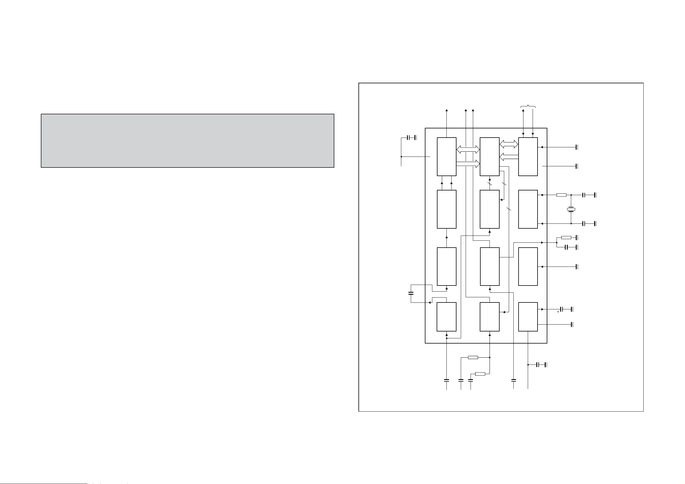
Page 37

8-1 8-1
AC POWER & DISPLAY & KEY
BOARD
IC BLOCK DIAGRAM - LCD DRIVER
HT1622
Block Diagram
TABLE OF CONTENTS
Internal IC Diagram ......................................................... 8-1
Layout Diagram - AC Power Board ................................. 8-2
Circuit Diagram - AC Power Board.................................. 8-3
Layout Diagram - AC Socket Board ................................ 8-4
Layout Diagram - Door Moter Board ............................... 8-4
Layout Diagram - RC Board ............................................ 8-4
Display Board .................................................................. 8-5
Key Board ........................................................................ 8-6
Speaker & Ant Board ....................................................... 8-7
Electrical Parts List .......................................................... 8-8
PIN DESCRIPTION - LCD DRIVER
HT1622
Pad Description
1CS
2RD I
3WR I
4DATAI/O Serial data input/output with Pull-high resistor
5 VSS
6 OSCI I
7 VDD Positive power supply
8 VLCD I LCD operating voltage input pad
9 IRQ
10, 11 BZ, BZ O 2kHz or 4kHz tone frequency output pair
12~14 T1~T3 I Not connected
15~22 COM0~COM7 O LCD common outputs
23~54 SEG0~SEG31 O LCD segment outputs
I
O
noitpircseDO/IemaNdaP.oNdaP
Chip selection input with Pull-high resistor. When the CS is logic
high, the data and command read from orwritten to the HT1622
are disabled. The serial interface circuit is also reset. But ifCS is
at logic low level and is input to the CS pad, the data and com
mand transmission between the host controller and the HT1622
are all enabled.
READ clock input with Pull-high resistor. Data in the RAM of
the HT1622 are clocked out on the rising edge of the RD signal.
The clocked out data will appear on the data line. The host con troller can use the next falling edge to latch the clocked out data.
WRITE clock input with Pull-high resistor. Data on the DATA
line arelatched intothe HT1622 on the risingedge ofthe WR signal.
Negative power supply, ground
If the system clock comes from an external clock source, the ex -
ternal clock source should be connected to the OSCI pad.
Time base or Watchdog Timer overflow flag, NMOS open drain
output
-
Page 38

8-2
8-2
LAYOUT DIAGRAM - AC POWER BOARD
TOP SIDE
LAYOUT DIAGRAM - AC POWER BOARD
BOTTOM SIDE
Page 39

8-3
CIRCUIT DIAGRAM - AC POWER BOARD
8-3
Page 40

8-4
8-4
LAYOUT DIAGRAM - AC SOCKET BOARD
TOP SIDE
LAYOUT DIAGRAM - AC SOCKET BOARD
BOTTOM SIDE
LAYOUT DIAGRAM - RC BOARD
TOP SIDE
LAYOUT DIAGRAM - RC BOARD
BOTTOM SIDE
LAYOUT DIAGRAM - DOOR MOTOR BOARD
TOP SIDE
LAYOUT DIAGRAM - DOOR MOTOR BOARD
BOTTOM SIDE
CIRCUIT DIAGRAM - RC BOARD
Page 41

8-5
8-5
LAYOUT DIAGRAM - DISPLAY BOARD
TOP SIDE
CIRCUIT DIAGRAM - DISPLAY BOARD
LAYOUT DIAGRAM - DISPLAY BOARD
BOTTOM SIDE
Page 42

8-6 8-6
LAYOUT DIAGRAM - KEY BOARD
TOP SIDE
CIRCUIT DIAGRAM - KEY BOARD
LAYOUT DIAGRAM - KEY BOARD
BOTTOM SIDE
Page 43

8-7 8-7
LAYOUT DIAGRAM - SP & ANT BOARD
TOP SIDE
CIRCUIT DIAGRAM - SP & ANT BOARD
LAYOUT DIAGRAM - SP & ANT BOARD
BOTTOM SIDE
Page 44

9-1
40
SET MECHANICAL EXPLODED VIEW
8
7
6
5
4
3
2
9
!
@
#
$
%
9-1
^
& *
1
·
›
?
31
º
ª
•
§
‡
£
™
(
)
¡
35
‹
36
Page 45

9-2
MECHANICAL & ACCESSORIES PARTS LIST
1 996510010723 LENS-CD DOOR /05/12
1 996510012871 LENS-CD DOOR /98
2 996510010722 DOOR-CD
3 996510010724 HOLDER CD DOOR CARRIER (L)
4 994000004302 COVER POWER BUTTON
5 996510010728 KNOB-VOLUME
6 996510010726 LENS DISPLAY
7 996510010725 HOLDER CD DOOR CARRIER (R)
8 996510010729 LENS BAR
9 996510010721 CABINET FRONT
11 996510010727 BUTTON POWER/SOURCE
15 994000004325 BELT MOTOR
17 996510010720 CABINET REAR FOR /12/05
17 996510012870 CABINET REAR /98
19-21 996520032987 STAND PORTION OF MCM277
22 9940 000 04323 CD DAMPER (BLACK) 20DEG
23 996510010437 CD MECHANISM M93BGP-BF
24 9940 000 01664 DAMPER GEAR ASSEMBLY
26 9940 000 03384 SPRING TORSION LEFT
28 994000004304 BRACKET OPEN/CLOSE BUTTON
T901 ! 994000004431 POWER TRASFO AC115/230V /98
T902 ! 994000004245 POWER TRASFO EI-28 AC230V /05/12
RF401 994000004237
Note: Only these parts mentioned in the list are
normal service parts.
FM FRONT END MODULE /05/12
29 994000004324 SPRING CONTROL PANEL
30 996510010730 BUTTON OPEN/CLOSE
31 994000004315 COVER PLAY BUTTON
32 994000004309 BUTTON FW/FF
33 996510010732 PANEL FUNCTION /12/05
33 996510012873 PANEL FUNCTION /98
34 996510010733 COVER FUNCTION PANEL 05/12/98
35 996510010731 BUTTON FUNCTION
36 994000004308 BUTTON PLAY
37 994000004333 IR LENS
38 994000004316 PULLEY SERVO MOTOR
39 994000004314 BRACKET FUNCTION PANEL
40 996510006485 CD/MCU BOARD ASS'Y (M93) /05/12
SPK 996510010734 SPEAKER BOX /05/12
FMA 994000004329 FM ANT WIRE 75R 1.0M
REM 996510028568 REMOTE CONTROL /05/12
REM 996510028568 REMOTE CONTROL /98
AML 994000004331 AM LOOP ANT 164X75MM
ACW ! 994000002223 POWER AC WIRE BSI /05
ACW ! 994000001675 POWER AC WIRE VDE 230V /12
ACW ! 994000002082 POWER AC CORD VDE 2C 1.5M /98
FFC1 994000004281 FFC 21P P1.25MM L110MM C TYPE
FF1 996510006481 FFC 7P P1.25MM L155MM D TYPE
T901 ! 994000004244 POWER TRASFO AC230V H50 /05/12
Page 46

8-8
& DISPLAY & KEY & SP & ANT
& RC & AC SOCKET & DOOR MOTOR BOARD
8-8
VR701 9940 000 04258 ROTARY ENCODER
9940 000 04251 EC TERMINAL 1P
65 1
10715
03605
1-060-010
MICRO PHONE JACK CKX-3.5-23
F901 9940 000 04243 FUSE PTU 1A 250V 3.9X10.5MM /37/98
RL901 9940 000 04246 RELAY DC6V AC10A /05/12/37
T901 9940 000 04244 POWER TRASFO AC230V /05/12
T902 9940 000 04245 POWER TRASFO AC230V /05/12
T901
!
!
!
!
!
9940 000 04431
POWER TRASFO AC115/230V /98
Note: Only these parts mentioned in the list are
normal service parts.
65 100 01366 IR SENSOR FM-6038TM2-5AN
Page 47

9-3
ELECTRICAL PARTS LIST
CF401 994000004236 FM CERAMIC FILTER 10M7 IC402 994000004234 VAR. CAP DIODE HN-1V02H
CF402
D100 996510010718 DIODE BZX79-C4V3 IC504 994000005674 IC BR24L02F-WE2
D128 994000004422 SCHOTTKY, PMEG2010 EA IC601 996500041701 IC TDA7468D SOUND SO28
D165 994000004422 SCHOTTKY, PMEG2010 EA IC610 994000004225 IC LM317P VOL REGULATOR
D300 996510006964 DIODE 1N5819 DO-41 IC701 994000004256 IC HT1622 LCD DRIVER
D302 996510000271 DIODE RLS4148 LL-34 IC801 994000004219 IC TDA1517 POWER AMPLIFIER
D303 994000004285 ZENER DIODE UDZS6.8B UMD2 IC901 996500040080 IC AP1117E33LA REGULATOR
D304 994000004285 ZENER DIODE UDZS6.8B UMD2 JK701 996510010715 USB JACK 4P
D305 994000004285 ZENER DIODE UDZS6.8B UMD2 JK702 994000003605 MICRO PHONE JACK
D401 996510007742 DIODE, HIGH BAS316 JK801 994000003318 HP JACK D3.6MM
D501 996510010716 DIODE,BZX79-C3V9 JK802 994000004248 SPK TERMINAL PST-403B-01
D502 996510010717 DIODE, BZX79-C4V7 TAPING L100A 994000004279 RADIAL IND. 1.2R 2.2UH +/-5%
D618 996510000271 DIODE RLS4148 LL-34 L155A 994000004279 RADIAL IND. 1.2R 2.2UH +/-5%
D750 996510000271 DIODE RLS4148 LL-34
994000004236 FM CERAMIC FILTER 10M7 IC501 996510006486 IC MN101CF91D MCU TQFP048
L156A 994000004279 RADIAL IND. 1.2R 2.2UH +/-5%
D801 996510000271 DIODE RLS4148 LL-34 L157A 994000004279 RADIAL IND. 1.2R 2.2UH +/-5%
D802 996510000271 DIODE RLS4148 LL-34 L159A 994000004226 RAD AXIAL IND. 100UH 3.5R
D803 996510000271 DIODE RLS4148 LL-34 L302 994000004289 TOROIDAL COIL 220UH +/-10%
D804 996510000271 DIODE RLS4148 LL-34 L303 994000004226 RAD AXIAL IND. 100UH 3.5R
D807 996510000271 DIODE RLS4148 LL-34 L304A 996510006488 INDUCTOR 10UH+/-10% 0.1R
D880 996510000271 DIODE RLS4148 LL-34 L403 996510010713 AM ANT 7MM 7M1A2204N
D881 994000004422 SCHOTTKY, PMEG2010 EA L605 994000004227 28UH CORE: 6T 715R 1.2A
D905 996510000271 DIODE RLS4148 LL-34 L620 994000004226 RAD AXIAL IND. 100UH 3.5R
D991 996510000271 DIODE RLS4148 LL-34 L702 994000004279 RADIAL IND. 1.2R 2.2UH +/-5%
D992 996510000271 DIODE RLS4148 LL-34 L810 994000004247 RADIAL AXIAL IND. 8.0UH 60MR
DZ401 996510010712 CH-DIODE, BZX284-C11 L811 994000004247 RADIAL AXIAL IND. 8.0UH 60MR
DZ801 996510007763 ZENER DIODE BZX55C15V L812 994000004247 RADIAL AXIAL IND. 8.0UH 60MR
DZ802 996500041721 ZENER DIODE BZX79-C10 L813 994000004247 RADIAL AXIAL IND. 8.0UH 60MR
DZ803 996510010711 ZENER DIODE BZX79-C5V6 L901 994000002657 AC LINE FILTER 3MH 1A
F601 ! 994000004229 FUSE PTU 2A 250V
F602 ! 994000004228 FUSE S506 T1.6AL 250V LED701 996510006484
F901 ! 994000004243 FUSE PTU 1A 250V 3.9X10.5MM
FF1 996510006481 FFC 7P P1.25MM L155MM M100 994000004253 DC MOTOR JQ32-55K415 DC3V
FMANT 994000004249 RCA JACK RCA-125 Q100 994000004275 TRANSISTOR 2SB709A
IC100 996500041888 IC MN6627954MA DSP Q101 996510006954 CH-TRANSISTOR,BC817-25
LCD701 996510006483 LCD DISPLAY 1/8 DUTY 1/4 STN
LED 4MM WHITE
LED702 996510000292 LED 3MM 3R4HD-7(RED)
IC102 994000004278 IC SCA105 MOTOR DRIVER Q102 996510006954 CH-TRANSISTOR,BC817-25
IC103 996500041890 IC MN101E01J TA MASKING Q103 994000004223 TRANSISTOR 3CA8550
IC104 994000005674 IC BR24L02F-WE2 Q104 996510006954 CH-TRANSISTOR,BC817-25
IC300 994000004287 IC OTI-6888G USB DECODER Q105 996510006954 CH-TRANSISTOR,BC817-25
IC301 994000004286 IC AP34063A CONVERTER Q106 994000004224 TRANSISTOR 3DA8050
IC302 996510010719 IC AT27C512R OTP EPROM Q107 994000004223 TRANSISTOR 3CA8550
IC302 994000004288 IC W27C512-45Z EPROM Q301 996510000939 TRANSISTOR BC807-25 PNP
IC401 994000004235 IC TEA5762H/V1 Q302 996510006954 CH-TRANSISTOR,BC817-25
Page 48

9-4
ELECTRICAL PARTS LIST
Q303 996510000939 TRANSISTOR BC807-25 PNP X300 994000004284 XTAL 14.318MHZ +/-20PPM 20PF
Q501 996510006954 CH-TRANSISTOR,BC817-25 X401 994000004231 X'TAL 75KHZ +/-20PPM DT381
Q502 994000004267
Q503 996510006954 CH-TRANSISTOR,BC817-25 X502 994000004266 X'TAL 4.194304MHZ 30PF
Q504 996510006954 CH-TRANSISTOR,BC817-25 XR11 994000004238 X'TAL 4.332MHZ +/-20PPM
Q601 994000004224 TRANSISTOR 3DA8050 HFE=120-200
Q610 994000004223 TRANSISTOR 3CA8550 HFE=120-220
Q631 994000004223 TRANSISTOR 3CA8550 HFE=120-220
Q701 994000004224 TRANSISTOR 3DA8050 HFE=120-200
Q702 994000004224 TRANSISTOR 3DA8050 HFE=120-200
Q803 994000004218 N-CHANNEL MOS TRANS PHP20N06T
Q905 994000004224 TRANSISTOR 3DA8050 HFE=120-200
RF401 994000004237
RI501 996510001366 IR SENSOR (OPTO)
RL901 ! 994000004246 RELAY ME-7-006-HSL DC6V AC10A
TRANSISTOR MPS8050S
FM FRONT END MODULE FE450-G11
X501 994000005671 XTAL 32.768KHZ +/-20PPM 12PF
SW501 994000004283 DETECT SWITCH DTS-18 1P1T
SW502 994000004283 DETECT SWITCH DTS-18 1P1T
SW506 994000004259 SWITCH TACT TSA-06430-150
SW701 994000004259 SWITCH TACT TSA-06430-150
SW702 994000004259 SWITCH TACT TSA-06430-150
SW703 994000004259 SWITCH TACT TSA-06430-150
SW704 994000004259 SWITCH TACT TSA-06430-150
SW705
SW708 994000004259 SWITCH TACT TSA-06430-150
SW709 994000004259 SWITCH TACT TSA-06430-150
SW710 994000004259 SWITCH TACT TSA-06430-150 Note: Only these parts mentioned in the list are
SW715 994000004259 SWITCH TACT TSA-06430-150 normal service parts.
SW716 994000004259 SWITCH TACT TSA-06430-150
SW717 994000004259 SWITCH TACT TSA-06430-150
T401 994000004518 AM IFT YELLOW 7MM C712KC-004
T402 994000004518 AM IFT YELLOW 7MM C712KC-004
T403 996510010714 AM IFT BLACK 7MM 7M4A2011N
T404 994000004519 FM IFT BLACK 7MM KS2599
T405 994000004517 AM OSC BROWN 7MM 7M1A2146
T901 ! 994000004244 POWER TRASFO AC230V H50.
994000004259 SWITCH TACT TSA-06430-150
T902 ! 994000004245 POWER TRASFO EI-28 AC230V
UR11 994000004239 IC SAA6588T RADIO RECEIVERS
UR12 996510001350 IC LM78L05 3-TERMINAL TO-92
VC403 994000001615 TRIMMER CAP 10PF N450
VR401 994000004232 VARI RES 100K 3P 1/10W+/-30%
VR701 994000004258 ROTARY ENCODER
X100 994000004273 CER RESONATOR 16.93MHZ +/-0.5%
X101 996510000295 XTAL 8.38MHZ +/-20PPM CAP=20PF
Page 49

SOFTWARE VERSION CHECKING
10-1
How to check Software Version on set Front Panel
Check software version:
(1)Plug in the set;
(2)Hold "PROGRAM" and "DBB" buttons together when set on "ECO Power" mode (LED light is on);
(3)The LCD will display the software version as " Mxxx xxx"
10-1
To clear all program station of tuner mode:
(1)Plug in the set;
(2)Hold "STOP" button when set on "ECO Power" mode (LED light is on);
(3)The LCD will display full screen,all program station of tuner will be cleared.
Starting Serial Number:
EF2A0913000001
Page 50

SET BLOCK DIAGRAM
11 - 1
11 - 1
Page 51

SET WIRING DIAGRAM
11 - 2 11 - 2
Page 52

12-1
PCB LAYOUT - MAIN BOARD (TOP VIEW)
12-1
Page 53

12-2
PCB LAYOUT - MAIN BOARD (BOTTOM VIEW)
12-2
Page 54

CIRCUIT DIAGRAM - MAIN BOARD
12-3
12-3
Page 55

13-1
PCB LAYOUT - CD & CD DOOR MOTOR & LIMIT SWITCH BOARD
(TOP VIEW)
13-1
Page 56

13-2
PCB LAYOUT - CD & CD DOOR MOTOR & LIMIT SWITCH BOARD
(BOTTOM VIEW) - ONLY FOR REFERENCE
13-2
Page 57

13-3
CIRCUIT DIAGRAM - CD & LIMIT SW BOARD
ONLY FOR REFERENCE
13-3
Page 58

14-1
PCB LAYOUT - AC POWER & HP JACK & SP & ANT JACK & RC BOARD
(TOP VIEW)
14-1
Page 59

14-2
PCB LAYOUT - AC POWER & HP JACK & SP & ANT JACK & RC BOARD
(BOTTOM VIEW)
14-2
Page 60

PCB LAYOUT - KEY BOARD
(TOP VIEW)
14-3
14-3
PCB LAYOUT - KEY BOARD
(BOTTOM VIEW)
Page 61

14-4
CIRCUIT DIAGRAM - KEY BOARD & AC POWER BOARD
14-4
Page 62

14-5
CIRCUIT DIAGRAM - HP JACK & SP & ANT & RC BOARD
14-5
Page 63

SET MECHANICAL EXPLODED VIEW
4
9
15-1
15-1
Page 64

15 - 2 15 - 2
(
)
T
3
996510010722
DOOR-CD
D7
996510026339
DIODE
MMBD4148W
MQ12
996510007048
CH
PNP SS8550LT1 SOT-23
L
8 9965 00 073
UTTON FUNCTION
LCD1
996510006483
LCD DISPLAY 1/8 DUTY 1/4 STN
MQ2
996510007048
CH TR. PNP SS8550LT1 SOT 23
15 996510010728
KNOB-VOLUME
Q4 996510006954
CH-TRANSISTOR BC817-25
MS506
996510026354
SWITCH TACT
KFC
A06
43
/12/05/
17 996510010726
LENS DISPLAY /12/05/37
SW705
996510026354
SWITCH
TACT
KFC A06 43
MU3
996510026378
IC 2M FLASH EN25P20 100GCP
34 996510026351
CD MECHANISM DM86-1
ZD1 996510026348
ZENER
DIODE BZX384-C3V3
U2
996510007057
IC AZ1117H-ADJTRE1REGULATORSOT
L
)(
D
MD2
996510026385
DIODE
LS4148
GS08
AQ01
996510006954
CH-TRANSISTOR
FOR ALI SOLUTION
MECHANICAL & ACCESSORIES PARTS LIS
ELECTRICAL PARTS LIST ELECTRICAL PARTS LIST
Loc. 12NC Description Loc. 12NC Description Loc. 12NC Description
MAIN UNIT DISPLAY/MCU PCB ASS'Y CD/USB PCB ASSY (ONLY FOR REFERENCE)
1 996510010723 LENS-CD DOOR FOR /12/05/37 D3 996510026339 DIODE MMBD4148W
D3 996510026385 DIODE LS4148-GS08
4 996510010733 COVER FUNCTION PANE
D7 996510026385 DIODE LS4148-GS08
7 994000004308 BUTTON PLAY IC1 996510026362 MCU CA6810F LQFP64
8 996510010731 BUTTON FUNCTION LCD1 996510006483 LCD DISPLAY 1/8 DUTY 1/4 STN
9
996510026403 PANEL FUNCTION /12/05/37 LED701
996510036396 LED 4MM WHITE
LED701 996510026368 LED 4MM WHITE
10 994000004309 BUTTON FW/FF LED702 996510000292 LED 3MM 3R4HD-7(RED) TAPING
11 994000004315 COVER PLAY BUTTON Q1 996500041698 CH-TRANS. 8050M SOT23
12 996510010725 HOLDER CD DOOR CARRIER (R) Q10 996510007049 CH-TR. PNP 3CA8550M SOT-23
13 996510010724
HOLDER CD DOOR CARRIER (L) Q2 996500041698 CH-TRANS. 8050M SOT23
16 996510026382 MECHANICAL SECTION (ALI) Q5 996510007049 CH-TR. PNP 3CA8550M SOT-23
16 994000004302 COVER POWER BUTTON Q6 996500041698 CH-TRANS. 8050M SOT23
17 996510010726 LENS DISPLAY
37 SW705 996510026354 SWITCH TACT KFC-A06-43
SW708 996510026354 SWITCH TACT KFC-A06-43
19 996510010730 BUTTON OPEN/CLOSE U1 996510026375 IC AZ393M-E1
20 996510010729 LENS BAR U2 996510026333 IC FM24C02-SO-T
23 996510010721 CABINET FRONT FOR /12 U2 996510026349 IC BR24C02SOP8
25 996510010727 BUTTON POWER/SOURCE VR701 994000004258 ROTARY ENCODER
29 994000004304 BRACKET OPEN/CLOSE BUTTON Y1 996510026359 XTAL 32768KHZ +/-30PPM
61 996510010720 CABINET REAR FOR /12 ZD5 996510026395 ZENER DIODE BZX384-C5V1
62-63-69
996510027355 STAND PORTION OF MCM277 ZD6 996510026395 ZENER DIODE BZX384-C5V1
MQ1 996500041698 CH-TRANS. 8050M SOT23
MQ11 996510007048 CH-TR. PNP SS8550LT1 SOT-23
-TR.
MQ13 996500041698 CH-TRANS. 8050M SOT23
MQ14 996500041698 CH-TRANS. 8050M SOT23
MQ2 996510007048 CH-TR. PNP SS8550LT1 SOT-23
MQ3 996500041698 CH-TRANS. 8050M SOT23
MQ4 996500041698 CH-TRANS. 8050M SOT23
MQ5 996500041698 CH-TRANS. 8050M SOT23
MQ6 996500040080 IC AP1117E33LA REGULATOR
MQ6 996500041892 IC AZ1117H-3.3 REGULATOR
MQ7 996510000285 TRANSISTOR 2SB1132R
-
MU1 996510026364 MCU ALI-M5673 QFP/128P
MU3 996510026376 IC 2M FLASH EN25F20-100GCP
MU3 996510026378 IC 2M FLASH EN25P20-100GCP
MU4 996510026353 IC SA1469XH 4CH MOTOR DRIVER
MU4 996510026398 IC MM1469XH 4CH MOTO DRIVER
MY1 996510026365 CER RESONTOR 1693MHZ +/-05
MZD3 996510026358 ZENER DIODE BZX384-C5V6
MZD4 996510026358 ZENER DIODE BZX384-C5V6
U1 996510026337 IC RT9702PB POWER SWITCHES-5
FMANT 996510000308 FM ANT WIRE 75R L1.0M
MAIN PCB ASSY
REM 996510028568 REMOTE CONTRO
SPKBOX 996510019466 SPK BOX FOR MCM277/12 IN PAIR
AMANT 996510026334 AM ANT ASSEMBLY OF MCM277
CD/USB PCB ASSY (ONLY FOR REFERENCE)
AUDIO PROCESSOR PORTION
AD02 996510026339 DIODE MMBD4148W
43 996510026377 DISPLAY/MCU BOARD ASSEMBLY MS501 996510026394 DETECT SWITCH DTS-18-PA46 1P1T AD02 996510026385 DIODE LS4148-GS08
36 996510026373 CD SERVO PWB ASSEMBLY MS502 996510026394 DETECT SWITCH DTS-18-PA46 1P1T AD03 996510026339 DIODE MMBD4148W
42 996510026336 MAIN PWB ASSEMBLY MD1 996510026339 DIODE MMBD4148W AD03 996510026385 DIODE LS4148-GS08
58 996510026343 AC POWER ASSEMBLY MD1 996510026385 DIODE LS4148-GS08 AJ2 994000004215 FILTER BEAD RH3.5X6X0.8
ACCOR
!
996510026381 AC POWER CORD HL-77 L1800MM MD2 996510026339 DIODE MMBD4148W AL02 994000004227 28UH CORE:T9X5X3 6T 715R 1.2A
-
-
MD4 996510026339 DIODE MMBD4148W AQ02 996510026397 TRANSISTOR 2SB772-P PNP
MD4 996510026385 DIODE LS4148-GS08 AQ03 996500041698 CH-TRANS. 8050M SOT23
MD5 996510026339 DIODE MMBD4148W AU03 996510001347 IC ET2314 SOUND SO28
MD5 996510026385 DIODE LS4148-GS08 F602
!
994000004228 FUSE S506 T1.6AL 250V
Page 65

15 - 3 15 - 3
MAIN PCB ASSY
KEY PCB ASSY
AC POWER ASSY
F602
!
996510026369
FUSE5K16A250V
D2
996510000271
DIODERLS4148LL 34
T902
!
996510026391
TRASFOEI 28230VT08628B
AC22
996510026338
MULTVARSDV1608H180C050
D5
996510026338
MULTVARSDV1608H180C050
JK802
994000004248
SPEAKERTERMINALPST‐403B‐01
D806
996510016501
DIODEIN4148FT 72
D8
996510026385
DIODELS4148 GS08
L812
994000004247
RADIALAXIALIND.8.0UH60MR
FD15
996510016501
DIODEIN4148FT‐72
SW704
996510026354
SWITCHTACTKFC‐A06‐43
Q804
996500041700
CH‐TRANS.DTC114YKANPN
SW715
996510026354
SWITCHTACTKFC‐A06‐43
p
FFB1
994000004215
FILTERBEADRH3.5X6X0.8
ACPOWERPORTION
Q
(FOR ALI SOLUTION)
ELECTRICAL PARTS LIST ELECTRICAL PARTS LIST ELECTRICAL PARTS LIST
Loc. 12NC Description Loc. 12NC Description Loc. 12NC Description
F602
F602
!
996510026357 FUSE50TT16AL250V D1 996510026338 MULTVARSDV1608H180C050 T901
!
996510026369 FUSE5K16A250V D2 996510000271 DIODERLS4148LL‐34 T902
!
996510026372 TRASFOUI39AC230VT08829A
!
996510026391 TRASFOEI‐28230VT08628B
FB1 994000004215 FILTERBEADRH3.5X6X0.8 D2 996510026339 DIODEMMBD4148W SP&ANTJACKPORTION
IC610 994000004225 ICLM317PVOLREGULATOR D2 996510026385 DIODELS4148‐GS08 D991 996510016501 DIODEIN4148FT‐72
Q1 994000004224 TRANSISTOR3DA8050HFE=120‐200 D3 996510026338 MULTVARSDV1608H180C050 D992 996510016501 DIODEIN4148FT‐72
ZD1 996510007003 ZENERDIODE6.2V1/2WTAPING D4 996510000271 DIODERLS4148LL‐34 D994 996510016501 DIODEIN4148FT‐72
ZD2 996510007762 ZENERDIODE9V11/2WTAPING. D4 996510026339 DIODEMMBD4148W D995 996510016501 DIODEIN4148FT‐72
POWERAMPLIFIERPORTION D4 996510026385 DIODELS4148‐GS08
FMANT 994000004249 RCAJACKRCA‐125
AD5 996510016501 DIODEIN4148FT‐72 D8 996510000271 DIODERLS4148LL‐34 L810 994000004247 RADIALAXIALIND.8.0UH60MR
D803 996510016501 DIODEIN4148FT‐72 D8 996510026339 DIODEMMBD4148W L811 994000004247 RADIALAXIALIND.8.0UH60MR
D806 996510016501 DIODEIN4148FT‐72 D8 996510026385 DIODELS4148‐GS08 L812 994000004247 RADIALAXIALIND.8.0UH60MR
D807 996510016501 DIODEIN4148FT‐72 FB701 994000004215 FILTERBEADRH3.5X6X0.8 L813 994000004247 RADIALAXIALIND.8.0UH60MR
D811 996510016501 DIODEIN4148FT‐72 JK701 996510010715 USBJACK4P ACSOCKETPORTION
F601
F601
F601
!
994000004229 FUSEPTU2A250V JK702 994000003605 MICROPHONEJACK L901 996510026396 LINEFILTER38mH38mH380MR
!
996510026387 FUSE30TS2A250V SW701 996510026354 SWITCHTACTKFC‐A06‐43 RCPORTION
!
996510026389 FUSE3N2A250V SW702 996510026354 SWITCHTACTKFC‐A06‐43 RI501 996510001366 IRSENSOR(OPTO)
FD05 996510016501 DIODEIN4148FT‐72 SW703 996510026354 SWITCHTACTKFC‐A06‐43
FU1 996500041892 ICAZ1117H‐3.3REGULATOR SW709 996510026354 SWITCHTACTKFC‐A06‐43
Q801 996510006954 CH‐TRANSISTOR SW710 996510026354 SWITCHTACTKFC‐A06‐43
‐
‐
‐
Q805 996510000939 TRANSISTORBC807‐25PNP SW716 996510026354 SWITCHTACTKFC‐A06‐43
Q806 996510006954 CH‐TRANSISTOR SW717 996510026354 SWITCHTACTKFC‐A06‐43
Q807 996510006954 CH‐TRANSISTOR
Note: Only these parts mentioned in the list are
normal service parts.
Q812 996510006954 CH‐TRANSISTOR
Q813 996510006954 CH‐TRANSISTOR
U801 996510001348 ICPOWERAMPLIFIERTFA9842BJ.
AC POWER ASSY
ZD804 996510007003 ZENERDIODE6.2V1/2WTAPING
TUNERPORTION HPJACKPORTION
FERRITE 996510026347 FERRITECORERH16x28x9 HJK1 996510026367 HPJACKCK‐35‐397PD36MM
FJ7 994000004215 FILTERBEADRH3.5X6X0.8 D905 996510016501 DIODEIN4148FT‐72
FQ02 996500041698 CH‐TRANS.8050MSOT23 D906 994000004422 SCHOTTKY
FQ06 996510006954 CH‐TRANSISTOR F901
FQ07 996510007049 CH‐TR.PNP3CA8550MSOT‐23 F901
FU01 996510026346 TUNERMODULE F901
!
994000004243 FUSEPTU1A250V3.9X10.5MM
!
996510026342 FUSE3N1A250V
!
996510026345 FUSE30TS1A250V
LPF1 996510026355 FMBPFILTERLPF88A1 Q905 994000004224 TRANSISTOR3DA8050HFE=120‐200
T5 996510026352 AMANTBLKYD‐482N10mm RL901
ZD3 996510016482 ZENERDIODEBZX79‐B3V9 RL901
!
994000004246 RELAYME‐7‐006‐HSLDC6VAC10A
!
996510026383 RELAYTV‐5DC6VAC10A
Page 66

16-1
REVISION LIST
1.0 Manual 3141 785 32370
Initial Service Manual released.
1.1 Manual 3141 785 32371
In this version, version /05 added.
1) P9-1 Mechanical and Accessories Partslist updated.
1.2 Manual 3141 785 32372
In this version, version /98 added.
1) P9-2 Mechanical and Accessories Partslist updated.
2) P1-2 PCBs Service Policy Variations added.
1.3 Manual 3141 785 32373
In this version,
1) P9-2 Mechanical and Accessories Partslist updated.
40 996510006485 CD/MCU BOARD ASS'Y (M93) /05/12 (WAS 996520033047)
1.4 Manual 3141 785 32374
In this version, Page 9-1 & Page 9-2 have been updated.
1) In Page 9-1: Item No. 33 & Item No.34 exchanged.
(the original sequence numbers -No.33 & No. 34 mixed up)
2) In Page 9-2: Pos. No. 33 ---->new 12nc for /98 added.
33 996510012873 PANEL FUNCTION /98
1.5 Manual 3141 785 32375
In this version, Ali solution is introduced and Chapter 10 to Chapter 15 have
been added.
1.6 Manual 3141 785 32376
In this version, Page 15-2 updated.
LED701 996510036396 LED 4MM WHITE (WAS 996510006484)
 Loading...