

Page 1

Sleek micro music system
MCM233
-/12/55/79/78/98
CONTENTS
Technical specification ..................................................................1-2
Service measurement setup..........................................................1-3
Service aids .................................................................................1-4
Instructions on CD playability ...............................................2-1.. 2-2
Block diagram................................................................................3-1
Wiring diagram ..............................................................................3-2
Main board
Circuit diagram ..................................................................4-1..4-2
Layout diagram..................................................................4-3..4-4
Key board
Circuit diagram .........................................................................5-1
Layout diagram.........................................................................5-2
LCD board
Circuit diagram .........................................................................6-1
Layout diagram.........................................................................6-2
Headphone board
Circuit diagram .........................................................................7-1
Layout diagram.........................................................................7-2
Exploded view diagram .................................................................8-1
Revision list....................................................................................9-1
©
Copyright 2010 Philips Consumer Electronics B.V. Eindhoven, The Netherlands
All rights reserved. No part of this publication may be reproduced, stored in a retrieval
system or transmitted, in any form or by any means, electronic, mechanical, photocopying,
or otherwise without the prior permission of Philips.
Published by LX 1042 Service Audio Subject to modification
Version 1.2
3141 785 34892
Page 2

TECHNICAL SPECIFICATION
1 - 2
Ampli?er
Total output power 2 x 10 W RMS
Frequency
response 80 H z - 16 kH z, ± 3 dB
Signal to noise ra o > 60 dB
MP3 link input
0.5 V RMS 20 k
Disc
Laser type Semiconductor
Disc diameter 12cm /8 cm
Support disc C D -DA , C D-R, CD -
RW, MP3-C D, W MACD
Audio DA C 24 Bits / 44.1 kH z
Total harmonic
distor on < 1.5%
Frequency
response
60 Hz -16 kHz(44.1
kHz)
Signal to noise ra o > 55 dBA
Tuner
Tuning range FM: 87.5 - 108 MHz
Tuning grid 50 KH z
Number of presets 20
Speakers
Speaker impedance
2 x 10 W , 6
General informa on
AC power 100-240V~ ,
50/60H Z
Opera on Power
Co nsump on
Standby Power Co nsump on 1 W
Eco Power Standby Power
Co nsump on
USB Direct Version 2.0/1.1
Dimensions
- Main Unit (W x H x D )
Weight
-MainUnit 2.7kg
15 W
0.8 W
565 x 245 x
104 mm
VERSION VARIATION
Type /Versions:
Board in used:
LCD BOARD
KEY BOARD
POWER KEY BOARD
OPEN/CLOSE BOARD
REMOTE INCEPT BOARD
RADIO BOARD
MAIN BOARD
USB BOARD
Features
RDS & DAB
VOLTAGE SELECTOR
ECO STANDBY - DARK
* TIPS : C -- Component Lever Repair.
M -- Module Lever Repair
√
-- Used
Service policy
Type /Versions:
Feature diffrence
/12
/12
MCM233
/55
/78
MCM233
C
C
C
C
/55
C
C
C
C
C
C
C
C
C
M/C
C
C
/78
√
C
C
C
C
C
C
C
C
√
√
/79
M/C
C
C
C
C
C
M/C
C
/79
√
/98
/98
Page 3
e
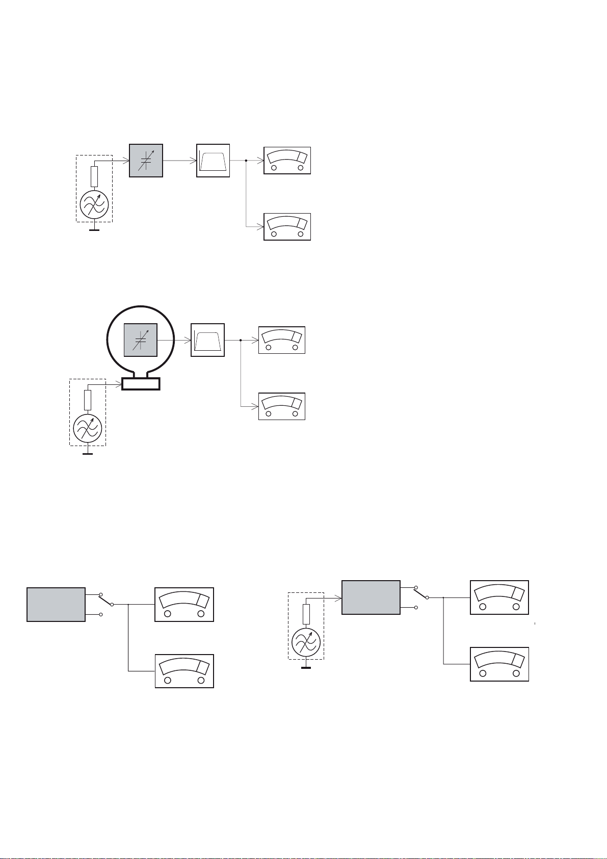
MEASUREMENT SETUP
Tuner FM
1-3
Bandpass
LF Voltmeter
e.g. PM2534
RF Generator
e.g. PM5326
DUT
250Hz-15kHz
e.g. 7122 707 48001
Ri=50:
S/N and distortion meter
e.g. Sound Technology ST1700B
Use a bandpass filter to eliminate hum (50Hz, 100Hz) and disturbance from the pilottone (19kHz, 38kHz).
Tuner AM (MW,LW)
RF Generator
e.g. PM5326
Ri=50:
DUT
Frame aerial
e.g. 7122 707 89001
Bandpass
250Hz-15kHz
e.g. 7122 707 48001
LF Voltmeter
e.g. PM2534
S/N and distortion meter
e.g. Sound Technology ST1700B
To avoid atmospheric interference all AM-measurements have to be carried out in a Faraday´s cage.
Use a bandpass filter (or at least a high pass filter with 250Hz) to eliminate hum (50Hz, 100Hz).
CD
Use Audio Signal Disc
(replaces test disc 3)
DUT
L
R
SBC429 4822 397 30184
S/N and distortion meter
e.g. Sound Technology ST1700B
LEVEL METER
e.g. Sennheiser UPM550
-
Recorder
Use Universal Test Cassette CrO2 SBC419 4822 397 30069
or Universal Test Cassette
LF Generator
e.g. PM5110
Fe SBC420 4822 397 30071
DUT
L
R
S/N and distortion met
e.g. Sound Technology ST170
LEVEL METER
e.g. Sennheiser UPM550
with FF-filter
Page 4

SERVICE AIDS
1-4
GB
All ICs and many other semi-conductors are
susceptible to electrostatic discharges (ESD).
Careless handling during repair can reduce life
drastically.
When repairing, make sure that you are
connected with the same potential as the mass
of the set via a wrist wrap with resistance.
Keep components and tools also at this
potential.
WARNING
GB
Safety regulations require that the set be restored to its original
condition and that parts which are identical with those specified,
be used
Safety components are marked by the symbol
!
.
ESD
CLASS 1
LASER PRODUCT
Lead free
Page 5

INSTRUCTIONS ON CD PLAYABILITY
Customer complaint
"CD related problem"
Set remains closed!
check playability
1
2 - 1
playability
ok ?
Y
Play a CD
for at least 10 minutes
check playability
playability
ok ?
Y
N
"fast" lens cleaning
check playability
playability
ok ?
N
3
N
Y
For flap loaders (= access to CD drive possible)
cleaning method
4 is recommended
add Info for customer
"SET OK"
2
return set
1 - 4 For description - see following pages
Exchange CDM
Page 6

INSTRUCTIONS ON CD PLAYABILITY
2 - 2
1
PLAYABILITY CHECK
For sets which are compatible with CD-RW discs
use CD-RW Printed Audio Disc....................7104 099 96611
TR 3 (Fingerprint)
TR 8 (600µ Black dot) maximum at 01:00
• playback of these two tracks without audible disturbance
playing time for: Fingerprint
Black dot from 00:50 to 01:10
• jump forward/backward (search) within a reasonable time
For all other sets
use CD-DA SBC 444A..................................4822 397 30245
TR 14 (600µ Black dot) maximum at 01:15
TR 19 (Fingerprint)
TR 10 (1000µ wedge)
• playback of all these tracks without audible disturbance
playing time for: 1000µ wedge 10seconds
Fingerprint 10seconds
Black dot from 01:05 to 01:25
• jump forward/backward (search) within a reasonable time
10seconds
4
LIQUID LENS CLEANING
Before touching the lens it is advised to clean the
surface of the lens by blowing clean air over it.
This to avoid that little particles make scratches on
the lens.
Because the material of the lens is synthetic and coated
with a special anti-reflectivity layer, cleaning must be done
with a non-aggressive cleaning fluid. It is advised to use
“Cleaning Solvent
The actuator is a very precise mechanical component and
may not be damaged in order to guarantee its full function.
Clean the lens gently (don’t press too hard) with a soft and
clean cotton bud moistened with the special lens cleaner.
The direction of cleaning must be in the way as indicated in
the picture below.
2
CUSTOMER INFORMATION
It is proposed to add an addendum sheet to the set which
informs the customer that the set has been checked
carefully - but no fault was found.
The problem was obviously caused by a scratched, dirty or
copy-protected CD. In case problems remain, the customer
is requested to contact the workshop directly.
The lens cleaning (method 3) should be mentioned in the
addendum sheet.
The final wording in national language as well as the printing
is under responsibility of the Regional Service Organizations.
Page 7
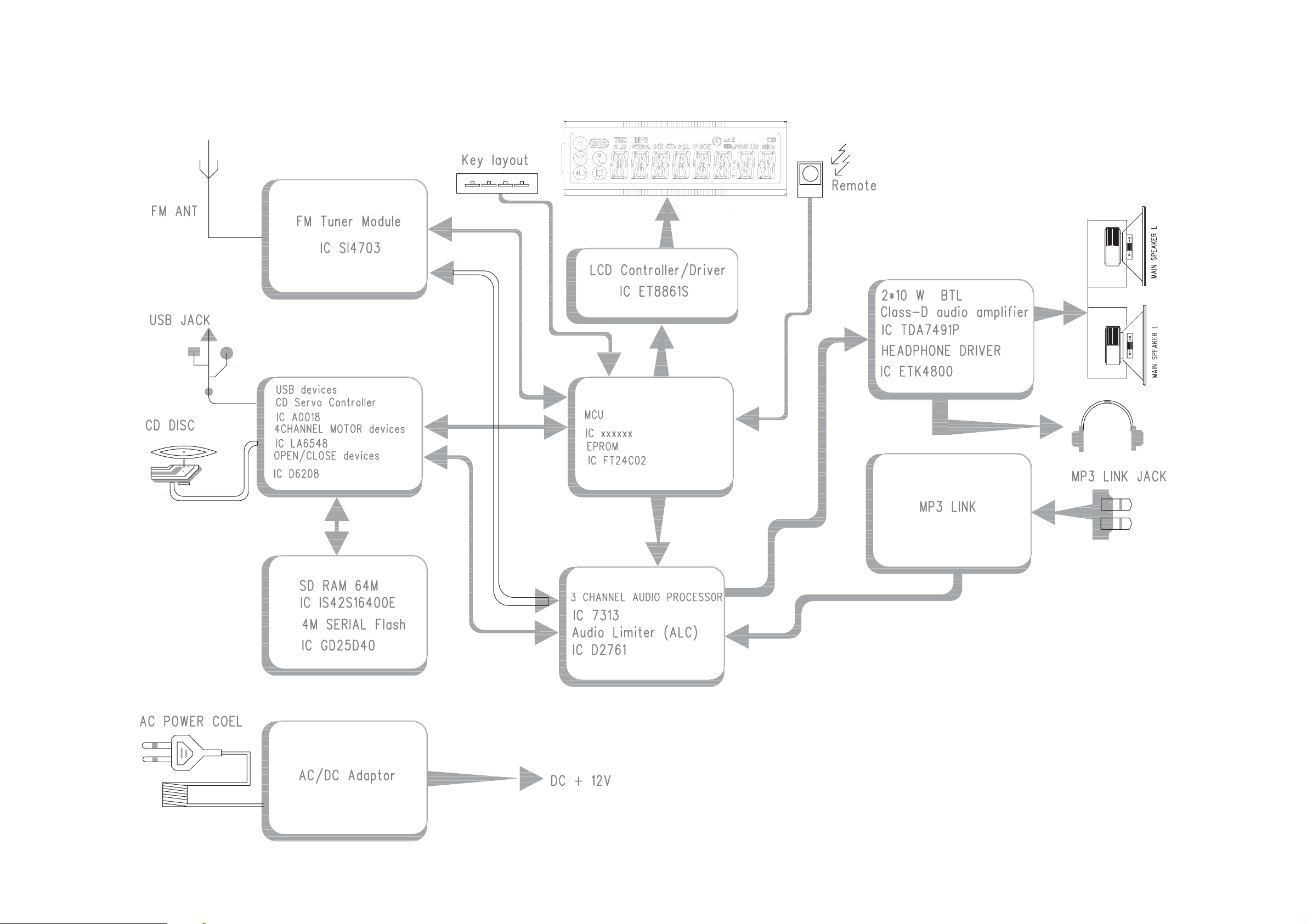
SET BLOCK DIAGRAM
3 - 1 3 - 1
Page 8

SET WIRING DIAGRAM
3 - 2 3- 2
Page 9

3-3 3-3
1)R
(BT3x12)
4)Remove the 4pcs screws(PT 3x8) on Main BD, rip off the black paper from FCC cable on CD deck, discharge Main BD and place it well;
Set disassembly diagram
omove the 12pcs screws
2)Remove the FFC cable on IPOD BD from Main BD,1st get remote control lens out, then remove the 4pcs screws (PA 2.3x8) which fix IPOD BD to discharge IPOD BD;
3)Remove all cables on Main BD;
PS: Get your hand to the Main BD as close as possible when you unplug the cables to avoid destroying cables;
on the side cabinet to discharge the rear cabinet and place it well;
pic1
pic1
pic1
pic1
pic1
pic1
IPOD cable
IPOD cable
IPOD cable
IPOD cable
IPOD cable
IPOD cable
IPOD cable
IPOD cable
IPOD Assembly
IPOD Assembly
IPOD Assembly
IPOD Assembly
IPOD Assembly
IPOD Assembly
IPOD Assembly
pic2
pic2
pic2
pic2
pic2
pic2
Remote
Remote
Remote
Remote
Remote
Remote
Control
Control
Control
Control
Control
Control
FFC cable
FFC cable
FFC cable
FFC cable
FFC cable
FFC cable
FFC cable
FFC cable
to CD
to CD
to CD
to CD
to CD
to CD
to CD
to CD
deck
deck
deck
deck
deck
deck
deck
deck
2P cable to
2P cable to
2P cable to
2P cable to
2P cable to
2P cable to
2P cable to
right SPK
right SPK
right SPK
right SPK
right SPK
right SPK
right SPK
Open
Open
Open
Open
Open
Open
Open
Open
button
button
button
button
button
button
button
button
DC cable
DC cable
DC cable
DC cable
DC cable
DC cable
DC cable
pic3
pic3
pic3
pic3
pic3
pic3
Display BD
Display BD
Display BD
Display BD
Display BD
Display BD
Display BD
Display BD
cable
cable
cable
cable
cable
cable
cable
cable
6P Deck cable
6P Deck cable
6P Deck cable
6P Deck cable
6P Deck cable
6P Deck cable
Motor
Motor
Motor
Motor
Motor
Motor
Motor
Motor
Cable
Cable
Cable
Cable
Cable
Cable
Cable
Cable
2P cable to
2P cable to
2P cable to
2P cable to
2P cable to
2P cable to
left SPK
left SPK
left SPK
left SPK
left SPK
left SPK
pic4
pic4
pic4
pic4
pic4
pic4
5)Remove the 4pcs screws(PT3x8) on CD deck, please add some soldering on the weld protect point and keep it in a ant-static bag;
6)Remove the 4pcs screws(PA 2.3x8 ) on Display BD, discharge Display BD and paste protect film on it and place it well;
7)Draw the CD door with your right hand,press one buckle with your left hand(pic 7-1),then press the other buckle(pic 7-2),discharge CD door and place it well;
protect
protect
weld
weld
point
pic5 pic6 pic7‐1 pic7‐2
buckle
buckle
pic7‐3
buckle
buckle
Page 10

CIRCUIT DIAGRAM - MAIN BOARD
PART 1
4 - 14 - 1
Page 11

CIRCUIT DIAGARM - MAIN BOARD
PART 2
4 - 2 4 - 2
Page 12

LAYOUT DIAGARM - MAIN BOARD
COMPONENT SIDE VIEW
4 - 3 4 - 3
Page 13

LAYOUT DIAGARM - MAIN BOARD
COPPER SIDE VIEW
4 - 4 4 - 4
Page 14

CIRCUIT DIAGRAM - KEY BOARD
5 - 1 5 - 1
Page 15

LAYOUT DIAGARM - KEY BOARD
5 - 2 5 - 2
Page 16

CIRCUIT DIAGARM - LCD BOARD
6 -1 6 - 1
Page 17

LAYOUT DIAGRAM - LCD BOARD
6 - 2 6 - 2
Page 18

CIRCUIT DIAGARM - HEADPHONE BOARD
7 - 1 7 - 1
6
5
4
CN501
3
2
1
L516
L515
L514 0
L513
0
0
0
USB501
USB
1
2
3
4
IC501
ETK4800
C514
CN502
TO main BD
1
2
3
4
5
6
7
8
9
10
GND
MUTE
VDD
HP_DET
AUX_LCH
GND
AUX_RCH
L501
L504
C519
102
22K
0
0
OUT_L
OUT_R
C518
102
22K
225
C503
IN4148
D501
C510
15K
R508
220P
VDD
R510 22K
22K
22K
R537
NO Headphone 0
YES Headphone 1
R509
15K
R511
1
2
3
4
C563
OUT1
IN1-
IN1+
GND
100/10
C509
C565
225
HP JACK
VCC
OUT2
IN2-
IN2+
104
R501
J501
220/10
8
7
VDD
6
5
15K
L505
L506
R503
15K
C505
220P
C511
C515
100/10
0
0
104
8550
Q503
R532
100K
22K
22K
C513
220/10
R534
C564
100/10
1K
Q504
C8050
R536
R535
C506
R533
22K
Q502
C8050
102
HP_LCH
HP_RCH
102
C517
JACK BOARD
22K
R515
22K
R512
R505
R513
L509
L510
L511
L512
0
0
L
0
R
0
G
J502
AUX JACK
Page 19

LAYOUT DIAGARM - HEADPHONE BOARD
7 - 27 - 2
Page 20

EXPLODED VIEW DIAGRAM
CDT
B4
C
8 - 1 8 - 1
B1
B7
K1
B5
MG
LBC
LCD601
FP
TO1
P
LL
B10
MGN
MP
MD
B9
CG
CM
B8
K3
SB
B2
RF
RC
RI
TO2
B6
Page 21

REVISION LIST
V
Version 1.0 (3141 785 34890)
* Initial Release
V
Version 1.1 (3141 785 34891)
* Add /55
V
Version 1.2 (3141 785 34892)
* Add /78
V
Version 1.3 (3141 785 34893)
* Add /98
9-1
 Loading...