

Page 1
3.0
2014
1428
Page 2

Page 3
Technical Specification
2.
module:MCM2300
TEST CONDITIONS:
1.POWER SUPPLY: AC.Accordiing to Ver
2.REF OUTPUT: 4 Ω 1W , Sound effect off
3.FM MONO: 22.5KHz Dev,1KHz MODULATION ,75Ω IMPEDANCE ,60dBu
4.FM STEREO : MAIN+SUB = 50KHz, PILOT : 10KHz,COMPOSITE: 40.0KHz
FM SECTION:
UNIT
1
2
3 dBf 20 26 10 10
4dB6560
5 40 25
6 S/N
7 % 1 2 0.2 0.2
8 dB45405858
9
10 1KHz dB 25 18 39 39
11 1KHz W _ 5±1dB 5.7/5.7 5.7/5.8
CD SECTION:
NO TEST ITEMS
1 1KHz %
2 dBA 82 77
3
4dB±3
5 CHANNEL SEPARATION
6nW_
7nW_
8 W _ 5±1dB
FM IF REJECTION 98MHZ S/N=26dB
IMAGE REJECT 98MHZ S/N=26dB
STEREO CHANNEL SEPARATION
TOTAL HARMONIC DISTORTION
FREQUENCY RESPONSE AT
LOUDSPEAKER OUT
Fvequency Range
26dB QUENTING SENSITIVITY
-3dB LIMITING POINT
OVERALL DISTERTION
MODULATION HUM
TUNING SENS
THD 10% POWER
S/N (1KHz,A-weightde)
CHANNEL DIFFERENCE (1KHz)
Residual noise (Vol min)
HUM
10% THE POWER
L/R
1K
10K
MHz
90.1 16 22 14 13
98.1 16 22 13 13
106.1 16 22 13 13
MONO 65 60 68 68
ST 55 50 64 65
90MHz dBf _ 19-35 18 18
98MHz dBf _ 19-35 18 18
106MHz dBf _ 19-35 18 18
30Hz dB _ ±3
20KHz dB _ ±3
LdB40
RdB40
LdB35
RdB35
dBf
dB
UNIT NOM. LIMIT
NOM.
87.5 87.5 87.5 87.5
108 108 108 108
≤0.8 ≤1 0.1/0.1
LIMITNO TEST ITEMS
_ 0.1/0.1 0.1/0.1
_68
_68
_64
_64
≤40
≤150 15
TEST DATA
42#
113 113
113 113
TEST DATA
42# 2#
86
∕∕
∕∕
1
5.7/5.7
2#
0.1/0.1
87
67
67
61
61
1
15
5.7/5.7
Page 4
Technical Specification
AUX SECTION:
NO
1 1KHz W _ 75±1dB
2 W _ 5±1dB 5.6/5.6 5.5/5.5
3
4%
5
6dB±3
7
8 mV 800 ±200 700 700
9 dBA
10 nW 11 nW -
USB SECTION:
NO TEST ITEMS UNIT
1 1KHz %
2 dBA 67 65
3
4dB0
5 CHANNEL SEPARATION
6nW_
7nW_
8 W _ 5±1dB
L/R OUTPUT POWER (10% THD, Ohm,1KHz)
FREQUENCY RESPONSE AT
LOUDSPEAKER OUT
CHANNEL SEPARATION
DIFFERENCE
(RATED OUTPUT
INPUT SENSITIVITY(RATED OUTPUT POWER AT
RESIDUAL NOISE (VOL.MIN.with signal ) A-WEIGHTED
TOTAL HARMONIC DISTORTION
FREQUENCY RESPONSE AT
LOUDSPEAKER OUT
THD 30% POWER
CHANNEL DIFFERENCE(1KHz)
LEVEL
S/N RATIO (1KHz,A-WEIGHTED)
HUM (VOL.MIN-MAX-20dB,without signal)
CHANNEL DIFFERENCE (1KHz)
TEST ITEMS
L/R
AMPLIFIER DISTORTION
1K
10K
FM 1KHz 67.5KHz DEV,68dBf
CD disc1-6dB track35
1KHz,10%THD
S/N (1KHz,A-weightde)
L/R
1K
10K
Residual noise (Vol min)
HUM
10% THE POWER
40Hz dB _ ±3
20KHz dB _ ±3
≤0.8 ≤1
L dB 40 _ 47 47
R dB 40 _ 47 47
L dB 35 _ 55 56
R dB 35 _ 55 56
dB - ±5 -0.8 -0.9
dB - ±3 1 0.9
82 77
NOM. LIMIT
≤1 ≤2
125Hz dB _ ±3
20KHz dB _ ±3
L dB 45 _ 69 68
R dB 45 _ 69 68
L dB 30 _ 59 59
R dB 30 _ 59 59
LIMITNOM.UNIT
_
≤150
≤40
≤2
≤40
≤150
TEST DATA
42# 2#
∕∕
∕∕
0.1/0.1 0.1/0.1
0.1/0.1 0.1/0.1
85 85
10 10
11
TEST DATA
42# 2#
0..1/0.1 0..1/0.1
86
∕∕
∕∕
0..1/0.1 0..1/0.1
11
11
5.6/5.6
85
5.6/5.6
Page 5

3.Safety instruction
1. General safety
Safety regulations require that during a repair:
. Connect the unit to the mains via an isolation transformer.
. Replace safety components indicated by the symbol
by components identical to the original ones. Any
only
other component substitution (other than original type)
may increase risk of fire or electrical shock hazard.
Safety regulations require that after a repair, you must
return the unit in its original condition. Pay, in particular,
attention to the following points:
. Route the wires/cables correctly, and fix them with the
mounted cable clamps.
. Check the insulation of the mains lead for external
damage.
. Check the electrical DC resistance between the mains
plug and the secondary side:
1) Unplug the mains cord, and connect a wire between
the two pins of the mains plug.
2) Set the mains switch the “on” position (keep the
mains cord unplug).
3) Measure the resistance value between the mains
plug and the front panel, controls, and chassis
bottom.
4) Repair or correct unit when the resistance
measurement is less than 1M
5) Ve
rify this, before you return the unit to the
customer/user (ref. UL-standard no. 1492).
6) Switch the unit “off”, and remove the wire between
the two pins of the mains plug.
¡
.
2.Laser safety
his unit employs a laser. Only qualified service personnel
T
,
may remove the cover, or attempt to service this device
(due to possible eye injury).
Laser device unit
Type : Semiconductor laser GaAlAs
Wavelength : 650nm (DVD)
: 780nm (VCD/CD)
Output power : 7mW (DVD)
: 10mW (DVD /CD)
Beam divergence: 60 degree
Note: Use of controls or adjustments or performance of
procedure other than those specified herein, may result in
hazardous radiation exposure. Avoid direct exposure to
beam.
Page 6
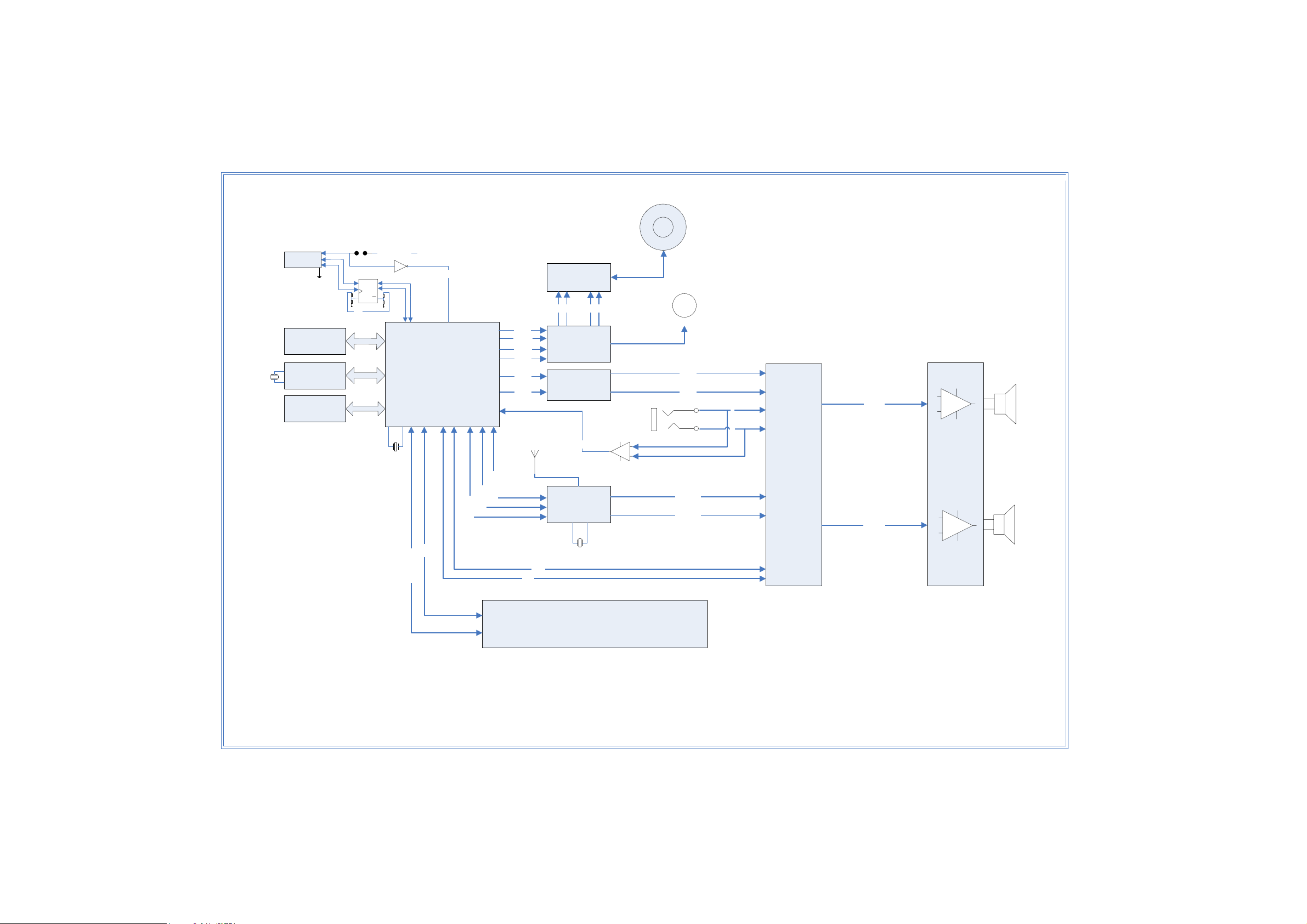
4.Set Block Diagram
.+
'LVF
'LVF
9
86%
3RUW
6ZLWFK
6
5
9%86
)/$6+
0
57&7LPH
]
4;
((3520
&
6
,,&
,,&
3
P$
6(7
4
4
&/5
,
.+
&XUUHQW'(7
&''HF
RGH
$LO$/$$
]
7562
'062
)062
)262
&'B
&'B5
/
$17
'$
77
)
&'
5&)LOWHU
(&2'(7
)
0
'RRUP
&'B/
&'B/
03/LQH,1
RWRU
/
5
/B287
/
$XGLR
3URF
HVVRU
$P
SOLILH
U
73$'
3//B5(6(7
3//B6&/
3//B6'$
'6$
'HW
6WDQGE\B
6&/
6,
.+]
6'$
7811B/
7811B/
37(
5B287
5
/(''LVSOD\
60
/('GLVSOD\
Page 7

5.Set Wiring Diagram
Page 8

DISMANTING DIAGRAM
6.
1)Dismanting of the top cabinet:Remove 10 screws A&B as indicated to loosen the top cabinet
A
2)Dismanting of the PCB board:
a: Remove 6 screws C as indicated to loosen the main board
b: Remove 9 screws D as indicated to loosen the display board
B
C
D
Page 9

5
4
3
2
1
7-1.Main Board Circuit Diagram
* CAUTION :
THE PARTS MARKED WITH ARE IMPORTANT PARTS ON THE SAFETY.
PLEASE USE THE PARTS HAVING THE DESIGNATED PARTS NUMBER WITHOUT FAIL.
D D
BT MODE SPARE
OFF PAGE
POWER CONNECTION
T1
EEL2
1
+
EC300
68uF/400V
!
1 2
1 2
D302
IN4007
D300
IN4007
1 2
1 2
D303
IN4007
D301
IN4007
!
C C
CY303 NC
CY300 250V/471PF
R306
NC
CX301 NC
R300
1.5M
R305
NC
3 1
0.1uF/275V
CX300
R301
1.5M
LF300
ET-20
24
CY301 250V/471PF
!
!
R321
100K
!
B B
VR300
HEL10D471K
12
!
R302
330K/1206
R303 330K/1206
IC300
3
OB227
3
2
R304
330K/1206
RI
FB
1
GND
10-23.5V
5
VDD
GATE
C303
313 200K/1206
R314 200K/1206
R
C317
68P/1KV
D304 1N4148
R312 100R
R311
4.7K/0805
6
4
CS
ZD301
NC
C301
0.1uF/X7
R323 1K/0805
C302
470PF/0805
+
EC301
22uF/50V
R310 10R/1206
R315 200K/1206
1
1 2
3
2
R3462.2R/1206
102P/1KV
D305
FR107
FB300 #3*6
Q300
MD70R900P
R3482.2R/1206
R3472.2R/1206
D306
M7(1N4007)
3
4
5 7
!
5
CY302 250V/471PF
!
F300
T1.0AL250V
12
!
1 2
LN
1
2
1
2
CON300
!
C300
473PF/100V
R322 2.2R/1206
ZD300
15V
IC302 EL817
4
3
!
C316
1KV/102P
8
9
10
D309 HER103
12
6
10
11
R316 330R
1
R317 3.3K
2
1 2
R338 10R/1206
D310 HER103
EC310
100uF/16V
EC308
100uF/16V
FB301 #3*6
C306
R340
102PF/1206
22R/1206
D308 SR360
C304
1KV/102P
D307 HER303
C318
104PF/X7R
3
IC301
WL431
R324
R318
1K
+
+
22R/1206
C305
0.1uF
L302
100uH/1A
C315
0.1uF
C310
0.1uF
AMP_GND
C311
0.1uF
C307
0.1uF
+5V
+
EC302
1000uF/25V
AMP_GND
R319
9.1K/1%
+
EC311
100uF/16V
GND
EC304
+
1000uF/16V
1000uF/10V
L300
10uH/2A
+
470uF/25V
(1+R320/R319)*2.495=Vo
R355
NC
R337
C314
0.1uF
100
BT_GND
R339
100K
+
EC305
L301
10uH/1A
C320
EC303
0.1uF
+5V
R320 10K/1%
R336 10K
K
C321
0.1uF
Q304
S8050
2 3
R332
10K
C308
0.1uF
AMP_VCC
AMP_VCC
BT_GND
1
10UF/16V
R325
NC
Q306
RCR1525SI
1
EC312
Q303
S8550
1
R331
10
A+5V
32
R335
1K
-P5V
C312
+
100PF
+P5V
23
K
Q302
RCR1525SI
1
R326
100K
100uF/25V
R327
1K
Q301
2N3904
2 3
Q310
RCR1525SI
1
R351
100K
R350
1K
2 3
32
EC306
1
32
Q305
2N3904
1
R328
100K
+
EC309
10UF/16V
R334 4.7K
R333
100
+
R329 4.7K
C313
0.1uF
BT_CTRL
Default Power ON(BT_CTRL)
ON
1
K
0
OFF
IC303
ADS5210/SOT-89
32
OUTVIN
GND
EC307
1
100UF/10V
R330
150R/1W
Default Power ON
01OFF
USB+5V
STBY_CTRL
BT_VCC
M33V
+
C309
0.1uF
+P5V
USB_VCC
A+5V
C201
0.1uF
ON
EQ_VCC
R221
NC/1K 1%
R222
R225NC
NC/560K 1%
USB_VCC
BT_VCC
-P5V
+P5V
USB+5V
AMP_VCC
M33V
STBY_CTRL
BT_CTRL
USB_Current
GND
AMP_GND
BT_GND
EQ_VCC
USB_CTRL
Design standard
+P5V
-P5V
M33V
VCC
AMP_VCC
R227 NC/0R
ZD200
NC
C202 NC/0.1uF
R223
2
3
NC/1K 1%
5
6
R226NC
R224NC
C200NC/1uF
8
-
+
+
-
4
U21
NC/LM393
1
7
USB_VCC (1)
BT_VCC (1)
-P5V (1,2)
+P5V (1,2)
USB+5V (1)
AMP_VCC (2,3)
M33V (1)
STBY_CTRL (1)
BT_CTRL (1)
USB_Current (1)
GND (1,2)
AMP_GND (3)
BT_GND (1)
EQ_VCC
USB_CTRL
0.2A
0.1A
0.8A
1.5A
1.2A
R219
NC/47K
R220 NC/1K
C206
NC/0.1uF
USB_C
1
Q200
NC/2N3904
USB_Current
2 3
Q311
2N3904
R349 4.7K
1
2 3
R341
A A
M2
M3.2-6.1
C319 0.1uF
1
5
M3.2-6.1
4
M1
M3
M3.2-6.1
1
M4
M3.2-6.1
1
1
SANREQI1
3
100K
2
USB_CTRL
1
Page 10

5
4
3
2
1
Main Board Circuit Diagram
D D
AMP_VCC
AMP_VCC
R405 220R
IC400
C422
1
C415
C414
0.1uF
0.1uF
C404 4.7uF
OUT_L
C405 4.7uF
OUT_R
C C
C420
470PF/NC
C419
470PF/NC
AMP-MUTE
AMP_STBY
MUTE
MUTE
PLAY
R410
220
R412
K
100
Q401
2N3904
K
1
2 3
AMP_VCC
AUDIO_MUTE
HMUTE
Unmute
L
B B
AMP_MUTE
R425 NC/1K
D400 1N4148
C418
0.1uF
R413
10K
1
R414
100K
2 3
Q400
2N3904
R411
100
2.2uF
2.2uF
K
C412
1uF
1uF
0.1uF
0.1uF
C413
C410
EC403
100uF/25V
+
C407
C406
100uF/25V
+
C411
EC404
PVCCL1
3
PVCCL2
5
LIN
8
8
AGND1
9
9
AGND2
6
RIN
4
MUTE
2
SDZ
7
BYP
11
VCLAMP
10
PVCCR1
12
PVCCR2
AMP_MUTE
AMP_STANDBY
TPA3124D2
AGND
25
R417 1K
R416 4.7K
PVSSL1
PVSSL2
OUTL
BSL
AVCC1
AVCC2
GAIN0
GAIN1
BSR
OUTR
PVSSR1
PVSSR2
24
23
22
21
20
19
18
17
16
15
14
13
D403
BAT54C
1
3
R415
100K
-A5V
shutdown
2
R403
1K/NC
R402 0R
R404 0R
R142
100K
C402
0.22uF
C408
0.1uF
C403
0.22uF
330pF
R408
10R
22uH/3.5A
+
C409
EC402
0.1uF
100uF/25V
2 1
R409
10R
C423
330pF
R418 100
R419 10
Q403
2N3904
1
R424
2 3
100K
L400
L401
22uH/3.5A
POWER
K
K
21
AMP_VCC
AMP_STBY
0STANDBY
1
R400
1K
R401
1K
C400
0.68uF/100V
C401
0.68UF100V
EC400
+
680uF/16V
EC401
+
680uF/16V
R406
1K
R407
1K
OUT_L+
OUT_L+
C416
0.1uF
C417
0.1uF
OUT_R+
OFF PAGE
DATA CONNECTION
OUT_R
OUT_L
AUDIO_MUTE
A_MUTE
AMP_STANDBY
POWER CONNECTION
-A5V
M33V
AMP_VCC
GND
AMP_GND
TP44
6
TP4
OUT_L+
OUT_R+
7
TP4
OUT_R (2)
OUT_L (2)
AUDIO_MUTE (1)
A_MU
TE (2)
AMP_STANDBY (1)
-A5V (1,4)
M33V (1,4)
AMP_VCC (2,4)
GND (1,2,4)
AMP_GND (4)
SP400
1
L+
2
L-
3
R+
4
R-
SAV-2
AMP_VCC
2
D401
BAV99
1
3
R420
4.7K
22uF/50V
AMPLIIER MU
A A
5
EC405
A_M
TE
U
R421
100K
R422 47K
+
TE
R423 0R
ZD400
15V
D402
1
BAT54C
2
3
Q402
1
S8550
2 3
EC406
+
220uF/25V
4
AMP_MUTE
C421 0.1uF
FB400 1000RH
3
AMP_GND
2
1
Page 11

Main Board Circuit Diagram
TUNER Audio
OP
5
4
3
2
1
OFF-PAGE
DATA CONNECTION
TP43
1617181920
NC
LOUT
GND
VDD
VIO
C64
0.1uF
TU_3V3
C70
1uF
15
NC
TU_LOUT
R92
100
C65
10uF
14
13
12
11
K
TU_ROUT
R74100R
R93
47
K
R94
47K
C62
1uF
C66
0.1uF
R95
100K
+
CE1
100uF/10V
EC20
47uF/10V
Q4
S80
0
5
2
1
+
C67
0.01uF
C73 4.7uF
C74 4.7uF
C75 4.7uF
C76 4.7uF
C77 4.7uF
FB3
3
300R/100MHz
R72
220R
ZD3
3.9V
+P5V
12
13
1415
LIN4
LIN3LIN2
LOUD_L
C79
0.1uF
11
RIN1
TU_ROUT
TU_LOUT
10
RIN2
C55 4.7uF
C68 4.7uF
9
RIN3
8
RIN4
R65
100
R80
100
C80
0.1uF
7
K
R77 10
K
R
ROUD_
R62 10
C81
0.22uF
6
ROUT
K
K
272PF/680PF
5
RIN
Y3
32.768KHZ
C53
22pF
FB2 100UH
R71
10K
R75 100R
R76 100R
C85
C84
470PF
470PF
FMI
C86
470PF
TUNER_XI
C60
C61
1uF
C87
470PF
C54
22pF
100pF
R67 100R
TUNER_SEN
TUNER_SCLK
TUNER_SDIO
C88
470PF
SI4702
NC
10K
10R
10R
TUNER_XI
R140
R60
R63
R61
U6
P3P2P1
NC
1
NC
2
FMI
3
FRGND
4
AMI
5
RST
SEN
SCLK
SDIO
678910
TUNER_XO
R91
47
K
ROUT
RCLK
TU_3V3
R68
10K
R69
10
K
TUNER_XO
R70
K
10
FB1 0R
2
D4
BAV9
D D
C C
CD_R
LINE_R
FM_R
CD_L
LINE_L
1
TU_RST
I2C_SCL
I2C_SDA
3
FMI
9
R82 2K
R83 0R
R84 0R
R89 2K
R90 0R
R59 30
R73 30
C63 100pF
C82
C83
272PF/680PF
3
4
TREB_R
C52 100pF
TREB_L
K
TU_RST
I2C_SCL
I2C_SDA
TU_RST (1)
I2C_SCL (1)
I2C_SDA (1)
AUDIO CONNECTION
-A5V
U5A
-
2
+
3
8 4
K
-A5V
U5B
-
6
+
5
NJM4558
8 4
+A5V
1
NJM4558
V
+A5
7
C56 4.7uF
C69 4.7uF
R64 1K
R79 1K
R66
100K
R81
100K
FM_R
C59
470pF
C72
470pF
FM_L
OUT_R
OUT_L
CD_L
CD_R
CTRL CONNECTION
U
TE
A_M
AUX_DET
POWER CONNECTION
AMP_VCC
-P5V
+P5V
GND
OUT_R (3)
OUT_L (3)
CD_L (1)
CD_R (1)
A_MU
TE (3)
T (1)
AUX_DE
AMP_VCC (3,4)
-P5V (1,4)
5V (1,4)
+P
GND (1,4)
MUTE_CIRCUIT
2
AGND
ZD5
9.1V
1
VDD
C78
0.1uF
EC21
+
1000uF/16V
R88 330R/1206
R78 330R/1206
R139 330R/1206
R131 330R/1206
EQ_VCC
ZD4
5.1V
AMP_VCC
R85
15K/5.1K
R86 51K/15K
+P5V
EC22
100uF/16V
+
R97 0R
R87
K
10
VCC
R96
1K
1
VCC
23
Q5
2N3906
Q6
2N3906
2 3
1
ZD6
NC
A_MUTE
U7
PT7314E
R343
100K
Q309
MPSA92
1
2 3
100uF/16V
23
R342
1K
Q308
2N3904
EC27
1
R345 4.7K
R344
100K
R106
10R
+
C104
EC2D2.5X5/AI
0.1uF
+A5V
EC26
100uF/16V
-P5V+P5V
+
STBY_CTRL
R107
10R
-A5V
C103
0.1uF
EC2D2.5X5/AI
C89
470PF
B B
FM_L
J1
3
2
1
3PIN/2.0mm
AUDIO IN :1V
AUX IN :2V
A A
R99 0R
C99 4.7uF
C100 4.7uF
R119 120K
R120 120K
C110 10uF
R105 470R
R108 470R
C101
470PF
R115 1M
LINE_R
LINE_L
C102
R109
47K
C109 47PF
-A5V
U8A
-
2
1
+
3
NJM4558
8 4
+A5V +A5V
470PF
C111 10uF
R110
47K
R121 1K
R118 24K
U8B
-
6
+
5
NJM4558
8 4
7
-A5V
C160
10uF
R98
47K
LIN1
LIN
LOUT
BIN_L
BOUT_R
BIN_R
BOUT_L
OUT_R
OUT_L
DGND
DATA
CLK
REF
16
17
18
19
20
21
22
23
24
25
26
27
28
C96
0.22uF
R116
47K
C173
0.1UF
C91 4.7uF
OUT_R
OUT_L
D6
BAV99
3
2
1
EC28
+
22uF/10V
AUX_DET
R122
20K
C105
0R
C107
0R
C92
0.47uF
R103
5.6K
C106
10K
C93
0.1uF
R111
NC
C174
0.1UF
C94
0.47uF
R104
5.6K
R117
47K
C95
0.1uF
C108
10K
+
EC232.2uF
+
EC242.2uF
R112
NC
C97
100PF
C98
100PF
R100 100R
R102 100R
+
EC25
22uF/16V
AMP_VCC EQ_VCC
I2C_SCL
I2C_SDA
5
4
3
2
1
Page 12

5
Main Board Circuit Diagram
TP6
CN1
VC
VCC
D
C
GND
LD
D D
C C
B B
CD5888
A A
VR
MD
F+
T-
T+
F-
SF-P200Z(FFC)
CON1
1
2
3
4
5
6
6PIN/2.0
CON2
5
4
3
2
1
5PIN/2.0
BIAS
MUTE
VINTK
U2
VINFC
TRB_1
REGO2
12345678910111213
RESETJ
TP1
1
2
R1 33K
3
E
4
5
A
6
B
7
8
F
9
10
11
12
13
14
15
16
SPIN+
SPINSLED+
SLEDLIMIT
R27 39K
R29 3K9
VINLD
TRB_2
OPOUT
VINSL+
REGO1
FWD
SLEGP VREF_16
FOCUS
R51 100R
C50
0.1uF
MAPUH
MBPUH
MCPUH
R6 33K
MDI
FOCUS+
TRACKTRACK+
FOCUS-
C5
0.1uF
R17
10K
TRACK
SPINDLE
R31 39K
R32 0R
21
22232425262728
N
GND
OPI
VCTL
REV
VCC1
VOTR-
MVCC
R42
18K
R48
24K
MDPUH
TP1
TP1
TP16
TP1
VCC2
VOTR+
HAVC
TP2
TP3
TP4
TP5
TP8
TP9
TP1
TP12
TP1
4
3V3SD
R11
5
10
K
7
TP18
C7
0.1uF
3V3SD
R18
10K
CLOSE_SW
OPEN_SW
DC_LOAD-
C21
0.1uF
DC_LOAD+
C29 0.01UF
R28
R30 1K
C30 0.47UF
C37 Cap 0.1U connect P8
C36 Cap 0.1U connect P19
1617181920
VOTK-
VOLD-
VOTK+
VOLD+
VOSL+
VOSL-
VOFC-
VOFC+
14 15
0.047uF
C40
R45 0R
R49
C41
3V3SD
3
2
VDD
2
RESET
GND
1
TNI
TPI
LD
0
3
0.01uF
Q20
ADS809
C1
0.1uF
220uF/16V
9
TP1
TP2
0
1
TP2
2
TP2
MUTE34
VREF_16
VREF_16
0R
XTRACK
XSPINDLE
VREF_16
SPINSPIN+
TRACKTRACK+
FOCUS+
FOCUSSLEDSLED+
DC_LOAD+
DC_LOADREV
FWD
XSLEGP
0R
XFOCUS
VREF_16
3V3SD
3V3SD
L2 33uH
EC2
MVCC
Del CON5
1
2
3
4
CON5
4PIN2.0mm
3V3SD
TP23
TP24
TP25
3V3SD
TP32
TP33
IP_TX
IP_RX
GND
for Debug
R56 100K
R58 100K
EC5
100uF/10V
R40 100K
3V3SD
TP38
TP39
HAVC
3V3SD
R2
10R
Q2
23
5
0
S85
1
C13 0.1uF
C14 0.1uF
C17 33pF
C23 33pF
CD_L
CD_R
MVCC
220uF/10V
FCS
FDO
WP
GND
U3
1
A0
2
A1
3
A2
4
GND
AT24C02
IP_TX
IP_RX
L1
80RH
EC3
47uF/16V
C8
0.1uF
EC7
10uF/10V
R19
10M
C27
1000PF
EC16
1
2
3
4 5
VCC
WP
SCL
SDA
LDO
LD
32.768KHz
C28
1000PF
U4
CS#
DO
WP#
GND
SFLASH
8
7
6
5
Y1
C36
0.1uF
HOLD#
EC1
47uF/10V
TP1
C6 0.1uF
EC6
10uF/10V
R23 2K
R24 2K
VCC
CLK
DI
R39 100R
R41 100R
4
1
SEV_3V
C12 0.1uF/0603
M33V_LDO
C18
0.1uF
L11 60RH
V18
R25
10K
D3
IN5819
C37
0.1uF
8
HOLD#
7
FCK
6
FDI
R35 10R
C38
0.1uF
For Servo Debug
TP40
FE
FELPFO
TP41
TE
TELPFO
TP42
SB
SBLPFO
3
C10
C9 0.1uF
0.1uF
SEV_3V
R174 0R
V18
C19
0.1uF
C24
0.1uF
EC9 2.2uF/50V
EC10 2.2uF/50V
R26
10K
R38 100K
3V3SD
I2C_SCL
I2C_SDA
VREF_16
3
EC4
10uF/16V
LDO
TPI
TNI
MCPUH
MBPUH
MDPUH
MAPUH
FELPFO
TELPFO
SBLPFO
+P5V
3V3SD
C39
0.1uF/0603
C4
0.1uF
C11 1uF
EC8
47uF/10V
M33V_CKG
100uF/10V
AUX_DET
AUD_3V3
EC12
M33V
I2C_SCL
R7 470
KEY_DET
TP7
XSLEGP
XFOCUS
XTRACK
MDI
U1
1
LDO
2
TP1
3
TP2
4
MC
5
MB
6
MD
7
MA
8
AVDD33_2
9
HAVC
10
V12
AVSS33_2
12
TELP
13
MPXOUT1
14
MPXOUT2
15
MPXOUT3
16
COSP
17
COSN
18
AVDD33_3
19
VTB
20
VTP
21
AVSS33_3
22
XTALI_32K
23
XTALO_32K
24
AVSS33_LDO_GND
25
AVDD33_LDO
26
AVDD18_LDO
27
AVDD18_LD0
28
XAMIN
29
AFMIN
30
AVDD33_CKG
31
NC
32
NC
33
AVSS33_CKG
34
AVDD18_1
35
AVSS18_1
36
LINEOUTL
37
LINEOUTR
38
AVDD33_AUD_GND
C31
10uF/16V
0.1uF
L30 60RH
49.9K/1%
D2
IN5819
1
EC13
R36
75K/1%
IPHONE_DP
R50
+
R53 1K
R55 1K
C2 0.1uF
2
Q1
S8050
3
125
126
127
128
MDI
TRO
FOO
GPWM
VREF
DP
DM
AVDD333_AUD
42
41
39
40
C32
L15
0.1uF
L16
60RH
60RH
DP
DM
R52
43.2K/1%
iPhone 1000MA
IPHONE_DM
R54
49.9K/1%
EC18
220uF/10V
8 1
VDD OI
7 2
COUT OO
6 3
SCL INT1
5 4
SDA VSS
SEV_3V
122
123
124
DMO
AVD33_1
AVSS33_1
GPIOA2/LCD_COM1
GPIOA3/LCD_COM2
GPIOA1/LCD_COM0
44
45
43
M33V
IC1
QX8563
121
46
V18_CORE
3
3V3SD
R510K
R310K
R410K
V18_CORE
C3 0.1uF/0603
M33V_PAD
115
116
117
118
119
120
FMO
VREF16
GND-CORE
BTN_ADIN1
BTN_ADIN2
BTN_ADIN3
VDD_CORE
ALi_M5677
VDD_CORE
GND_CORE
GPIOA7/LCD_SEG2
GPIOA6/LCD_SEG1
GPIOA4/LCD_COM3
GPIOA5/LCD_SEG0
GND_PAD
51
49
48
47
50
52
C33
M33V_PAD
0.1uF
FB12 0R
EC19
10uF/10V
3
R8 1K
109
110
111
114
112
113
GPIOJ1
GPIOJ2
VDD_PAD
GND_PAD
GPIOJ0/URRX
VDD_PAD
GPIOB5/LCD_SEG3
GPIOC0/LCD_SEG6
GPIOB7/LCD_SEG5
GPIOB6/LCD_SEG4
53
54
57
55
58
56
+
DM
IPHONE_DM
USB_DM
22pF(NC)
105
106
107
108
GPIOI4
GPIOI5
GPIOI6
GPIOI7/URTX
GPIOC3/LCD_SEG9
GPIOC2/LCD_SEG8
GPIOC1/LCD_SEG7
GPIOC4/LCD_SEG10
60
62
59
61
USB_SW_3V3IPAD_5VUSB_VCC
USB_SW_3V3
C112
0.1uF
10
C49
15pF
Y2
32.768KHZ
C51
GNDI2C_SDA
MUTE34
CLOSE_SW
R0402
IP_TX
IP_RX
TU_RST
LIMITXSPINDLE
AUDIO_MUTE
IR
103
104
GPIOI3
GPIOI2/IRC
GPIOI0/I2CM_CLK
GPIOI1/I2CM_DAT
GPIOH7/FM_32K
PRSTB
GPIOH6/SFCLK
GPIOH5/SFCSB
GPIOH4/SFD1
GPIOH3/SFDO
GPIOH2/DOCD_CLK
GPIOH1/DOCK_DAT1
GPIOH0/DOCD_DATO
GPIOG7
GPIOG6
GPIOG5
GPIOG4
GPIOG3/SDD2
GPIOG2/SDD3
VDD_PAD
GND_PAD
GPIOF3/SDCMD
GPIOF2
GPIOF1/SDCLK
GPIOF0/SDD0
GPIOE7/SDD1
GPIOE6
GPIOE5
GPIOE4
GPIOE3
GPIOE2
GPIOE1
GPIOE0
GPIOD7
GPIOD6
GPIOD5
GPIOD4
GPIOD3
GPIOD2
GPIOD1
GPIOD0
GPIOC5/LCD_SEG11
GPIOC6/LCD_SEG12
GPIOC7/LCD-SEG13
631164
U20
ET7222
VCC
9
HSD1+
OE
8
HSD2+
HSD1-
7
HSD2-
D+
GNDD-
2
1
OFF PAGE
Audio Connect
3V3SD
R57 NC/10K
R33 NC/10K
I2C_SDA
102
101
100
99
98
97
96
95
94
93
92
91
90
89
88
87
86
85
84
83
82
81
80
79
78
77
76
75
74
73
72
71
70
69
68
67
66
65
L3 60RH
L4 60RH
L5 60RH
L6 80RH
R12 1K
R124 100R
R123 100R
I2C_SCL
USE_RCOSC
RESETJ
FCK
FCS
FDO
FDI
OPEN_SW
USB_Current
VOLVFD_DATA
VFD_CLK
VFD_STB
VOL+
STBY_CTRL
M33V_PAD
BT_CTRL
4052_SW
USB_SW
USB_CTRL
AMP_STANDBY
REV
FWD
CD_EN
USB SW
USB_SW
1
S
DP
2
IPHONE_DP
3
USB_DP
4
56
Disable
USB
iphone
USB_SW
/
0
1
OE
1
0
0
R9 10K
R10 10K
R37 10K
R127 10K
R125 10K
R13 10K
R14 10K
R15 10K
R126 10K
R16 10K
R34 10K
R20 10K
R21 10K
R22 10K
M33V_PAD
EC15
47uF/10V
V18 V18_CORE
2012.06.30 Change DSA DATA
PIN91 VFD_DATA Change to PIN92
PIN90 VFD_CLK Change to PIN91
PIN88 VFD STB Change to PIN90
2012.06.30 Change Power_DET to STBY_CTRL
10KR128
10KR129
10KR130
M33V_PAD
10KR143
C34
0.1uF
L19 60RH
-P5V
4052_SW
BT_VCC
IP_TX
IP_RX
BT_GND
VOLVOL+
M33V
IR
VFD_DATA
VFD_CLK
VFD_STB
KEY_DET
+P5V
Power ON
Power OFF
C35
0.1uF
R43 0R
R44 220R
R46 220R
R47 220R
C42100PF
C43100PF
1
0
C44100PF
C45100PF
C114 NC/0.1uF
C46100PF
C470.1uF
M33V
C48100PF
L7
L8
L9 60RH
L10
L12
L13 80RH
USB+5V
C115 NC/100PF
C116100PF
C1170.1uF
CD_R
CD_L
DATA Connection
TU_RST
I2C_SCL
I2C_SDA
AMP_STANDBY
AUDIO_MUTE
AUX_DET
USB_Current
Power Connection
USB_VCC
-P5V
+P5V
USB+5V
M33V
BT_VCC
BT_CTRL
STBY_CTRL
GND
BT_GND
USB_CTRL
60RH
60RH
60RH
60RH
L33 NC/80RH
L37 NC/60RH
L32 NC/80RH
L38 NC/0R
L20 NC/0R
L31 NC/80RH
L21 80RH
L22 60RH
L23 60RH
L24 20R
L25 60RH
L26 60RH
L39 60RH
L27 60RH
L28 80RH
L29 80RH
47uF/10V
C15 0.1uF
C16 0.1uF
C20 0.1uF
C22 0.1uF
C25 0.1uF
C26 0.1uF
EC11 47uF/16V
L14 PTC/1.5A
100uF/10V
USB_DM
USB_DP
ZD1
5.6V
EC17
EC14
TP51
USB_VCC
ZD2
5.6V
L18
0R
TP52
TP50
TP48
TP26
TP49
TP34
ion
CD_R (2)
CD_L (2)
TU_RST (2)
I2C_SCL (2)
I2C_SDA (2)
AMP_STANDBY (3)
AUDIO_MUTE (3)
AUX_DE
T (2)
USB_Current (4)
USB_VCC (4)
-P5V (2,4)
5V (2,4)
+P
USB+5V (4)
M33V
BT_VCC (4)
BT_CTRL (4)
STBY_CTRL (4)
GND (2,4)
BT_GND (4)
USB_CTRL (4)
SEV_3V3
AUD_3V3
M33V_PAD
M33V_CKG
M33V_LDO
3V3SD
CON3
4
3
2
1
4PIN2.0mm
TP27
TP29
TP31
TP53
TP28
TP30
TP36
TP35
TP37
GND
DM
DP
VCC
(4)
CON7
16
15
14
13
12
11
10
9
8
7
6
5
4
3
2
1
16pin,1.0mm
5
4
3
2
1
Page 13

7-2. Main Board Layout Diagram
Page 14

Main Board Layout Diagram
Page 15

8-1.Display Board Circuit Dirgram
2
1
LED2
A_7316
AT
3
DIG4
DIG5
DIG6
DIG7
DIG8
DIG9
C4
0.1uF
16
SEG9
IR_+3.3V
DIG10
17
SEG10
EC2
100uF/10V
SVCC
3
R12 10K
C5
100pF
Q1
2
1
BAT54C
4 5
+5V
VOL1
204
16B_24
45
1
3
2
1
3
2
R15
R14
100R
100R
VOL_UP
VOL_DOWN
SEG1
SEG2
SEG3
SEG4
SEG5
SEG6
SEG7
DIG1
DIG2
DIG
1
2
3
4
5
6
7
8
9
10
11
12
13
14
15
Grid6
Grid7
SEG14/Grid5
SEG13/Grid6
SEG12/Grid7
SEG10/KS10
SEG9/KS9
SEG8/KS8
SM1628
IR
R17 100R
+
C11
0.1uF
SEG1
SEG2
GND
Grid1
Grid2
GND
Grid3
Grid4
GND
VDD
B B
Grid1
R4 51K
DATA
CLK
STB
VDD
SEG4
SEG5
SEG6
SEG7
SEG8
SEG9
SEG10
Grid2
RF
U1
Grid3
OUT
GND
VCC
Grid4
Grid5
U2
1
OSC
2
DI/O
3
CLK
4
STB
5
KEY1
6
KEY2
7
VDD
8
SEG1/KS1
9
SEG2/KS2
10
SEG3/KS3
11
SEG4/KS4
12
SEG5/KS5
13
SEG6/KS6
14 15
SEG7/KS7
1
2
3
EC1
100uF/10v
SEG4
SEG5
SEG6
Grid1
Grid2
Grid3
Grid4
VDD
Grid5
Grid6
Grid7
SEG1
SEG2
SEG3
SEG7
SEG8
SEG3
28
27
26
25
24
23
22
21
20
19
18
17
16
IR_+3.3V
R13 10K
C6
100pF
CON1
4P2.0
1
2
3
4
CON2
3
2
1
3PIN/2.0mm
IR_+3.3V
MP3_L
MP3_R
220uF/10v
R6
C2
220PF
47K
R26 0R
R19 0R
R20 0R
EC4
C3
220PF
+
R3 1K
R5 1K
R7
47K
D
AGN
IR_+3.3V
SVCC
FB1 PTC/1A
R1 15R
R2 15R
FB2 7RH
FB3 1000RH
FB4 1000RH
FB5 1000RH
FB6 1000RH
R11 100R
JK2
USB1(A_TYPE)
1
5V
2
DM
3
DP
4
GND
1
2
3
4
5
R16
100R
C1
0.1uF
JK1
AUX_IN
G1
G2
5
6
LED1
Red_LED
1
12
3
2
Q2
2SC8550
VOL_DOWN
VOL_UP
IR_+3.3V
IR
DATA
CLK
STB
KEY
+5V
EC3
100uF/10V
+5V
R8
10K
R9
10K
C7
100PF
R10
10K
C8
100PF
FB13 1000RH
FB14 1000RH
FB15 1000RH
FB17 1000RH
FB18 1000RH
FB19 1000RH
FB20 1000RH
FB21 1000RH
FB22 1000RH
C9
100PF
FB23 NC
C10 0.1uF
CON3
10
9
8
7
6
5
4
3
2
1
10PIN/FCC
A A
R18 4.7K
SW1
1
1
2
2
NEXT
C18
102P
3
4
3
4
SW4
1
1
2
2
OPEN/CLOSE
3
3
4
4
1
KEY
C12
102P
1
2
R21 1K/1%
SW2
1
2
Power/standby
R22 1.2K/1%
C13
102P
3
3
4
4
1
2
SW6
1
2
Soure
C14
102P
3
4
3
4
R23 1.8K/1%
SW7
1
1
2
2
PLAY/PAUSE
C15
102P
3
4
R24 1.8K/1%
C16
102P
SW5
3
4
1
1
2
2
STOP
3
3
4
4
R25 2.7K
SW3
1
1
2
2
FWD
C17
102P
3
4
3
4
2
Page 16

8-2 Display Board layout Diagram
Page 17

Display Board layout Diagram
Page 18

9.Mechanical Exploded View
001
005
004
006
003
007
008
Page 19

10. TROUBLE SHOOTING
A:NO POWER OUTPUT
Check EC300 is with 310V
direct voltage or not
YES
Check switching tube Q300 is
with 310V voltage or not.
YES
Check the fifth feet of IC300
is with around 14V or not.
YES
D308 5.2V,D307 17.5V regular
voltage
B: NO DISPLAY
NO
NO
NO
Check F300,
LF300,D300~D303
Check R346~R348,T1
Check R310,D306,T1,IC301
Check IC303 is with 3.3V
voltage output or not
YES
Check Y1(32.768KHZ)if start
oscillation or not
YES
Check R44,R46,R47 LED display
drive signal CLK,DATE,STB is
normal or not
YES
Display is OK
NO
NO
NO
Check D308 is with 5.2V
voltage or not
YES NO
Check D308,IC301,IC302
Check Y1,C17,C23,U4,Q20
etc. components
Check U1,CON8 and U2 on
display board,CON3,FFC
cabel
Page 20

TROUBLE SHOOTING
C: NO SOUND
YES
Check power amplifier D307 if
with 17.5 voltage or not
YES
Check U7:1st feet of PT7314
is with 9V power supply or not
YES
Check 2nd feet of IC400
STANDBY function if with high
level or not,4th feet MUTE
function is with low level or
not
YES
Check U1 No.102 and 103 feet
SCL,SDA waveform is normal or
not
YES
NO
NO
NO
NO
Refer to A maintenance
method
Check power supply circuit:
Q308,Q309,ZD5 etc.
component
Check MUTE circuit: D400,
Q400,Q401,Q402,D402 and
STANDBY circuit: D403,Q403
etc component
Check 12C circuit: U1,U3,
R39,R41,R100,R102 etc
component
Audio output ok
D: NO DISC
YES
Check U1's power supply
3.3V,1.8V voltage,U2's 5V
YES
Push the laser head to outer
rail, check if can auto
introskip by power on
YES
NO
NO
Check D308,IC301,IC302,D3,Q301,
Q302 etc. components
Check Q20's RESET signal, R42,U1,
U2's SLEGP signal and 6PIN soft flat
cabel
Page 21

TROUBLE SHOOTING
Look into if with focus action
and laser output or not
YES
NO
Check R47,R48,U1,U2's
FOCUS,TRACK signal,Check
Q2 is with LD signal,
loader and main board 's
Disc is running or not
YES
CD Reading ok
E: NO USB
Check USB socket if with 5.2V
voltage or not
YES
NO
NO
Check R29,U1,U2's SPINDLE
signal and 6PIN soft flat
Check Q310,Q311,main
board and display board's
USB connecting wire.
YES
Check L301 if with 5.2V
voltage or not
NO
Refer to A's maintenance
method
Check 1st feet of U20(USB_SW)
if with low level or not
YES
Check DM,DP signal if normal
or not
YES
USB reading OK
NO
NO
Check U1
Check L15,L16,ZD1,
ZD2,U1,U20 etc components
Page 22

11. Software upgrade & procedure to restore product setting
eset to defaults:
1. R
n, long press “Stop” button quickly, it will display the software version. Then short press the
Plug i
“Stop” button, it will display “Reset”, and access “STANDBY” in a while. When it displays “--”,
it has been reset to defaults.
2.Check the software version:
Plug
in, long press the “STOP” button quickly, it will display the software version.
3.Software-upgrade method:
the updated software(boot.ali and nemo.bin) into USB, insert it into the CD MINI, you
Copy
will hear “Do” sound for two times, which means it starts to upgrade. About 40 seconds later, you
will keep hearing “Do” sound which means the upgrade is done. At this time you can unplug the
power and remove the USB. Noted: Should not blackout during the upgrade, otherwise the
machine will crash (it can not start up and the display shows nothing.). After the crash, the only
solution is to remove the FLASH IC (U4, EN25F20), rewrite the software on programmer or
directly replace a new FLASH with effective program.
Page 23

V3.0 2014.07.12 add /77 /79 version
 Loading...