

Micro System
MCM207/12
TABLE OF CONTENTS
Page
Location of PCBs ..................................................................1-2
Specifi cations .......................................................................1-3
Measurement Setup .............................................................1-4
Service Aids, Safety Instruction, etc .....................................1-5
CD Playability Check ..................................................1-6 to 1-7
Software Version Checking .....................................................2
Set Wiring & Block Diagram ....................................................3
Main & Tuner & Headphone Boards ........................................4
MCU & USB Board .................................................................. 5
Display & Key Board................................................................6
Set Mechanical Exploded View & Parts List ............................7
Revision List ............................................................................8
©
Copyright 2009 Philips Consumer Electronics B.V. Eindhoven, The Netherlands
All rights reserved. No part of this publication may be reproduced, stored in a retrieval system or
transmitted, in any form or by any means, electronic, mechanical, photocopying, or otherwise without
the prior permission of Philips.
Published by SL 0916 Service Audio Printed in The Netherlands Subject to modification
Version 1.1
CLASS 1
LASER PRODUCT
3141 785 33921
PCBS LOCATION
1-2
DISPLAY & KEY BOARD
CASS. BOARD
MAIN BOARD
MCU BOARD (CD BOARD)
TUNER BOARD
USB BOARD
VERSION VARIATIONS
Board in used:
MAIN BOARD
MCU BOARD (CD BOARD)
USB JACK BOARD
DISPLAY & KEY BOARD
TUNER BOARD
HEADPHONE BOARD
CASS. BOARD
* TIPS : C -- Component Lever Repair.
M -- Module Lever Repair
-- Used
x
HEADPHONE BOARD
Type /Versions:
Service policy
/12 /05
C
C/M
C
C
M
C
M
/37
MCM207
/55
16/85/
89/

SPECIFICATIONS
1-3
Amplifier
Rated Output Power 2X5W RMS
Frequency Response 60 - 16kHz, ±3dB
Signal to Noise Ratio >62dB
Disc
Laser Type Semiconductor
Disc Diameter 12cm/8cm
Support Disc CD-DA, CD-R,
CD-RW, MP3-CD,
WMA-CD
Audio DAC 24Bits / 44.1kHz
Total Harmonic
Distortion
Frequency Response 60Hz -16kHz
S/N Ratio >62dBA
<1%
Tuner
Tuning Range FM: 87.5 - 108MHz;
MW: 531 - 1602kHz
Tuning grid 50 kHz (FM); 9 kHz
(MW)
Total Harmonic
Distortion
Signal to Noise
Ratio
<3%
>50 dB
Tape deck
Frequency response
Normal tape (type I)•
Signal-to-noise ratio
Normal tape (type I)•
Wow and utter <0.4% JIS
125 - 8000
Hz (8 dB)
40 dBA
Speakers
Speaker Impedance 4ohm
General information-Specs
Power supply Model: GFP181T-
1512-1 or
GFP181DA-1512-1,
Input: AC100-240V~,
50/60Hz, 0.35A
Output: DC15V,
1.2A
Operation Power
Consumption
Standby Power
Consumption
Dimensions
Main Unit (W x H •
x D)
Speaker Box (W x •
H x D)
Weight
With Packing•
Main Unit•
Speaker Box•
26 W
<4 W
152 x 228 x 222mm
146 x 232 x 140mm
6.6 kg
1.95 kg
2 x 1.2 kg
Supported MP3 disc formats
ISO9660, Joliet•
Maximum title number: 512 (depending •
on le name length)
Maximum album number: 255•
Supported sampling frequencies: 32 kHz, •
44.1kHz, 48 kHz
Supported Bit-rates: 32~256 (kbps), •
variable bit rates
e
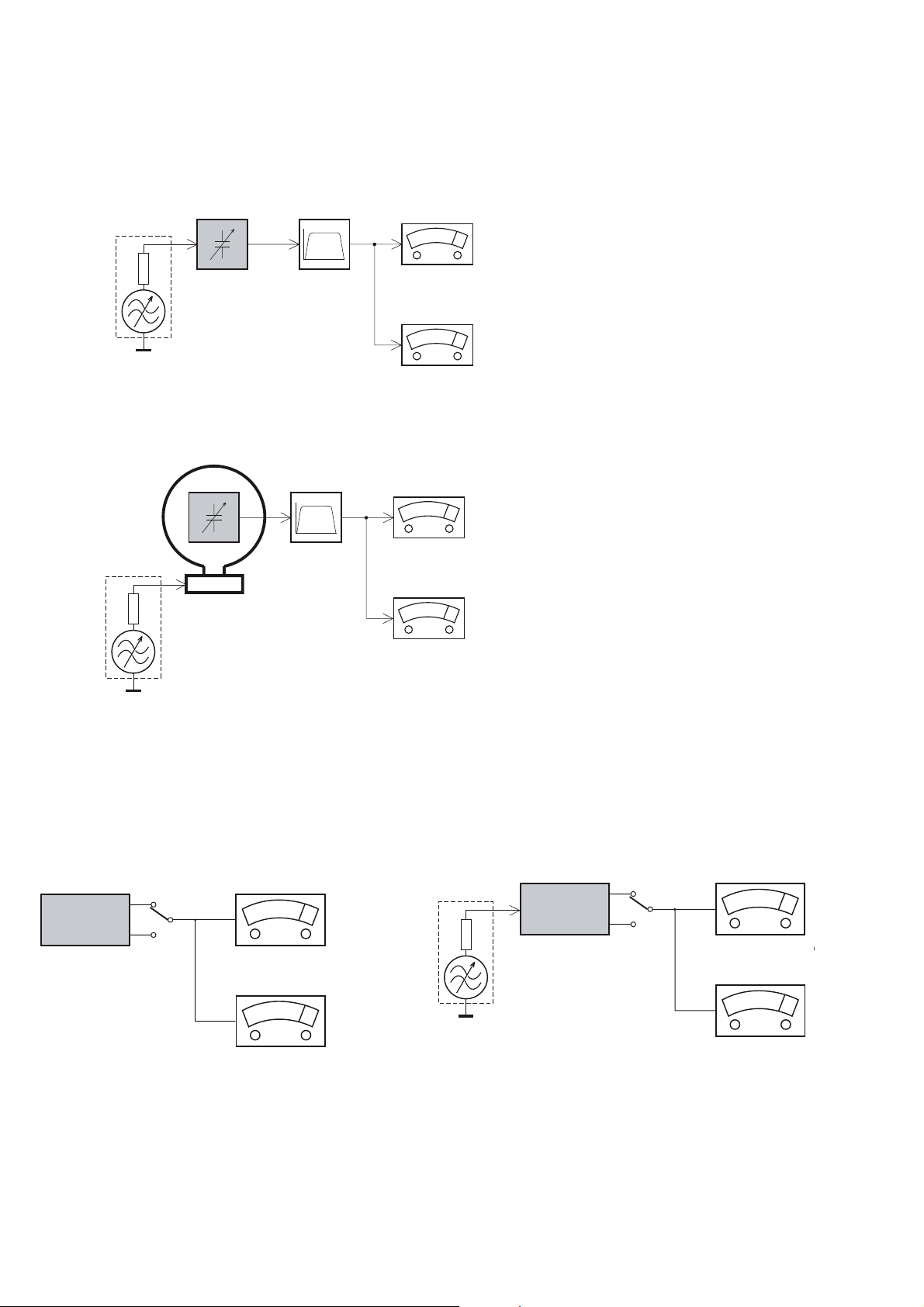
MEASUREMENT SETUP
Tuner FM
1-4
Bandpass
LF Voltmeter
e.g. PM2534
RF Generator
e.g. PM5326
DUT
250Hz-15kHz
e.g. 7122 707 48001
Ri=50:
S/N and distortion meter
e.g. Sound Technology ST1700B
Use a bandpass filter to eliminate hum (50Hz, 100Hz) and disturbance from the pilottone (19kHz, 38kHz).
Tuner AM (MW,LW)
RF Generator
e.g. PM5326
Ri=50:
DUT
Frame aerial
e.g. 7122 707 89001
Bandpass
250Hz-15kHz
e.g. 7122 707 48001
LF Voltmeter
e.g. PM2534
S/N and distortion meter
e.g. Sound Technology ST1700B
To avoid atmospheric interference all AM-measurements have to be carried out in a Faraday´s cage.
Use a bandpass filter (or at least a high pass filter with 250Hz) to eliminate hum (50Hz, 100Hz).
CD
Use Audio Signal Disc
(replaces test disc 3)
DUT
L
R
SBC429 4822 397 30184
S/N and distortion meter
e.g. Sound Technology ST1700B
LEVEL METER
e.g. Sennheiser UPM550
-
Recorder
Use Universal Test Cassette CrO2 SBC419 4822 397 30069
or Universal Test Cassette
LF Generator
e.g. PM5110
Fe SBC420 4822 397 30071
DUT
L
R
S/N and distortion met
e.g. Sound Technology ST170
LEVEL METER
e.g. Sennheiser UPM550
with FF-filter
SERVICE AIDS
1-5
GB
All ICs and many other semi-conductors are
susceptible to electrostatic discharges (ESD).
Careless handling during repair can reduce life
drastically.
When repairing, make sure thatyouare
connected with the same potential as the mass
of the set viaawrist wrap with resistance.
Keep components and tools also at this
potential.
WARNING
GB
Safety regulations require that the set be restored to its original
condition and that parts which are identical with those specified,
be used
Safety components are marked by the symbol
!
.
ESD
CLASS 1
LASER PRODUCT
Lead free
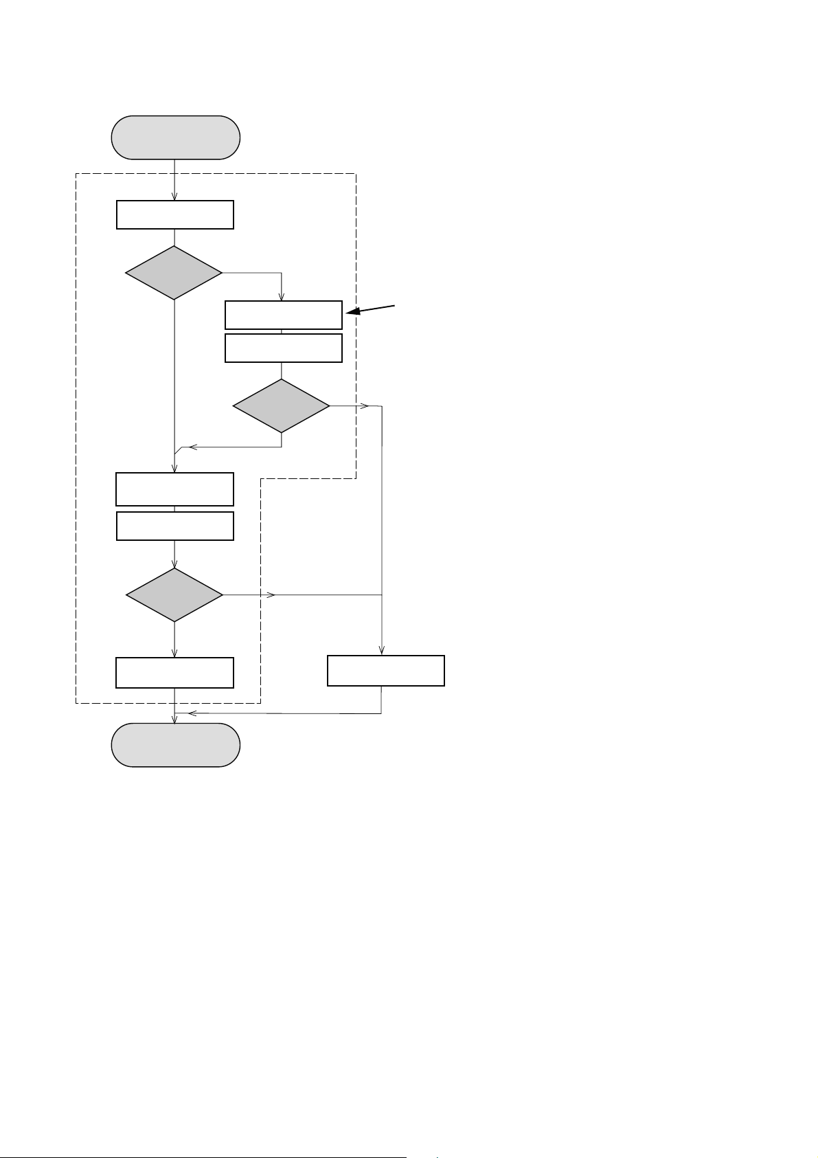
INSTRUCTIONS ON CD PLAYABILITY
Customer complaint
"CD related problem"
Set remains closed!
check playability
1 - 6
playability
ok ?
Y
Play a CD
for at least 10 minutes
check playability
playability
ok ?
Y
N
"fast" lens cleaning
check playability
playability
ok ?
N
For flap loaders (= access to CD drive possible)
cleaning method
N
Y
is recommended
add Info for customer
"SET OK"
return set
- For description - see following pages
Exchange CDM
INSTRUCTIONS ON CD PLAYABILITY
1 - 7
PLAYABILITY CHECK
For sets which are compatible with CD-RW discs
use CD-RW Printed Audio Disc ....................7104 099 96611
TR 3 (Fingerprint)
TR 8 (600µ Black dot) maximum at 01:00
• playback of these two tracks without audible disturbance
playing time for: Fingerprint
Black dot from 00:50 to 01:10
• jump forward/backward (search) within a reasonable time
For all other sets
use CD-DA SBC 444A..................................4822 397 30245
TR 14 (600µ Black dot) maximum at 01:15
TR 19 (Fingerprint)
TR 10 (1000µ wedge)
• playback of all these tracks without audible disturbance
playing time for: 1000µ wedge 10seconds
Fingerprint 10seconds
Black dot from 01:05 to 01:25
• jump forward/backward (search) within a reasonable time
10seconds
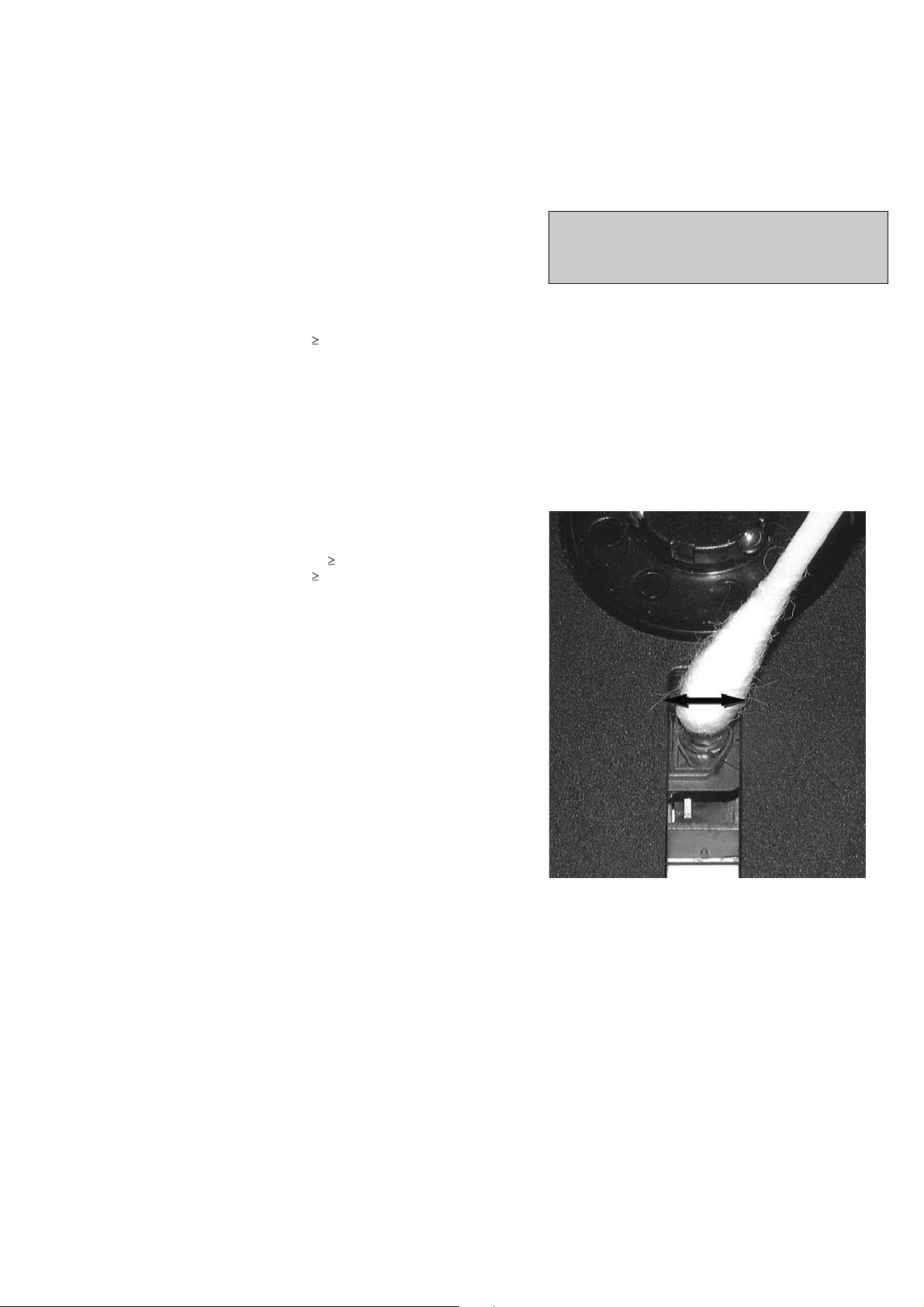
LIQUID LENS CLEANING
Before touching the lens it is advised to clean the
surface of the lens by blowing clean air over it.
This to avoid that little particles make scratches on
the lens.
Because the material of the lens is synthetic and coated
with a special anti-reflectivity layer, cleaning must be done
with a non-aggressive cleaning fluid. It is advised to use
“Cleaning Solvent
The actuator is a very precise mechanical component and
may not be damaged in order to guarantee its full function.
Clean the lens gently (don’t press too hard) with a soft and
clean cotton bud moistened with the special lens cleaner.
The direction of cleaning must be in the way as indicated in
the picture below.
CUSTOMER INFORMATION
It is proposed to add an addendum sheet to the set which
informs the customer that the set has been checked
carefully - but no fault was found.
The problem was obviously caused by a scratched, dirty or
copy-protected CD. In case problems remain, the customer
is requested to contact the workshop directly.
The lens cleaning (method ) should be mentioned in the
addendum sheet.
The final wording in national language as well as the printing
is under responsibility of the Regional Service Organizations.

SERVICE TEST PROGRAM
2-1
2-1
How to read software version,
1. Plug A/C to power on and NO DISC mode, press and hold PLAY and DBB buttons for 5 seconds,
LCD Display shows existing CD software version "CD - V029" and MCU software version “MCU - 013”.
3-1
3-1
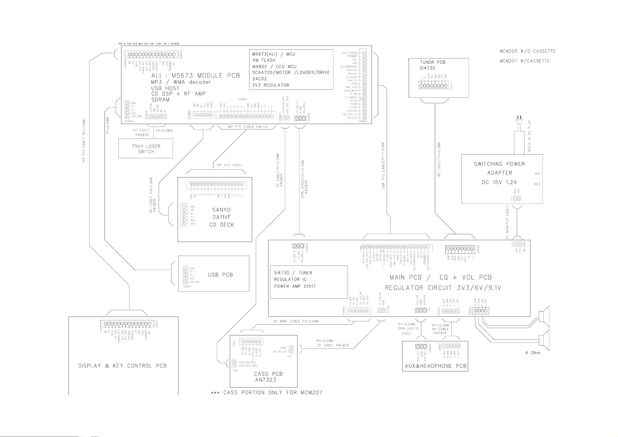
SET BLOCK & WIRING DIAGRAM

MAIN & TUNER &HEAD-
PHONE BOARD
TABLE OF CONTENTS
Main Board Layout Top View ........................................... 5-2
Main Board Layout Bottom View ..................................... 5-3
Tuner Board Layout Diagram ........................................... 5-4
Headphone Board Layout Diagram ................................. 5-5
Circuit Diagram ................................................................ 5-6
4-1 4-1

4-2 4-2
PCB LAYOUT - MAIN BOARD (TOP VIEW)

4-3 4-3
PCB LAYOUT - MAIN BOARD (BOTTOM VIEW)
4-4
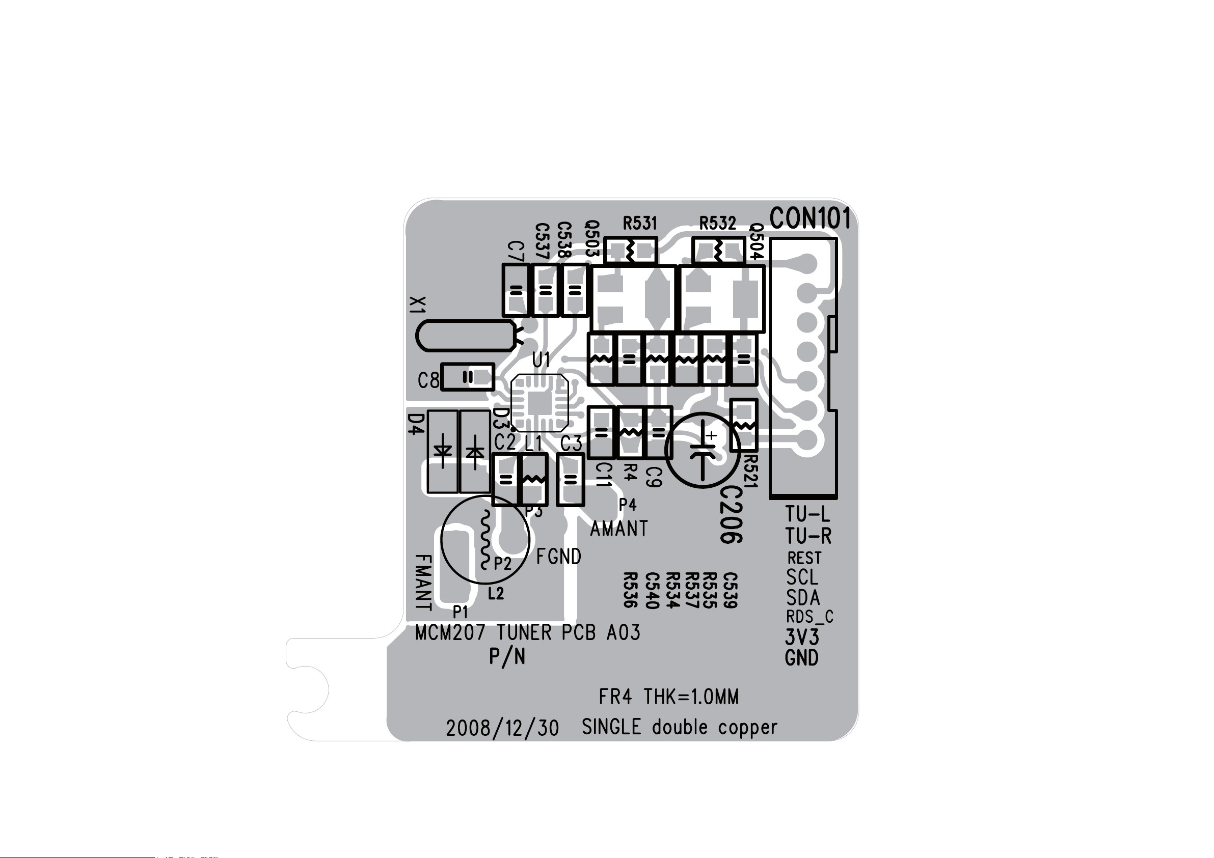
4-4
PCB LAYOUT - TUNER BOARD (ONLY FOR REFERENCE, MODULE SWAP )

4-5
4-5
LAYOUT DIAGRAM - HEADPHONE BOARD

4-6
4-6
CIRCUIT DIAGRAM - MAIN & TUNER & HP BOARD

5-1 5-1
MCU & USB BOARD
TABLE OF CONTENTS
MCU Board Layout Top View ..........................................5-2
MCU Board Layout Bottom View .....................................5-3
USB Jack Board Layout Diagram .....................................5-4
Circuit Diagram .................................................................5-5

5-2 5-2
PCB LAYOUT - MCU BOARD (TOP VIEW)

5-3
PCB LAYOUT - MCU BOARD (BOTTOM VIEW)
5-3

LAYOUT DIAGRAM - USB BOARD
5-4
5-4

5-5
CIRCUIT DIAGRAM - MCU & USB BOARD
5-5

DISPLAY/KEY BOARD
TABLE OF CONTENTS
Layout Top View ............................................................... 6-2
Layout Bottom View ..........................................................6-3
Circuit Diagram ................................................................. 6-4
6-1
6-1

6-2
PCB LAYOUT - DISPLAY/KEY BOARD (TOP VIEW)
6-2
6-3
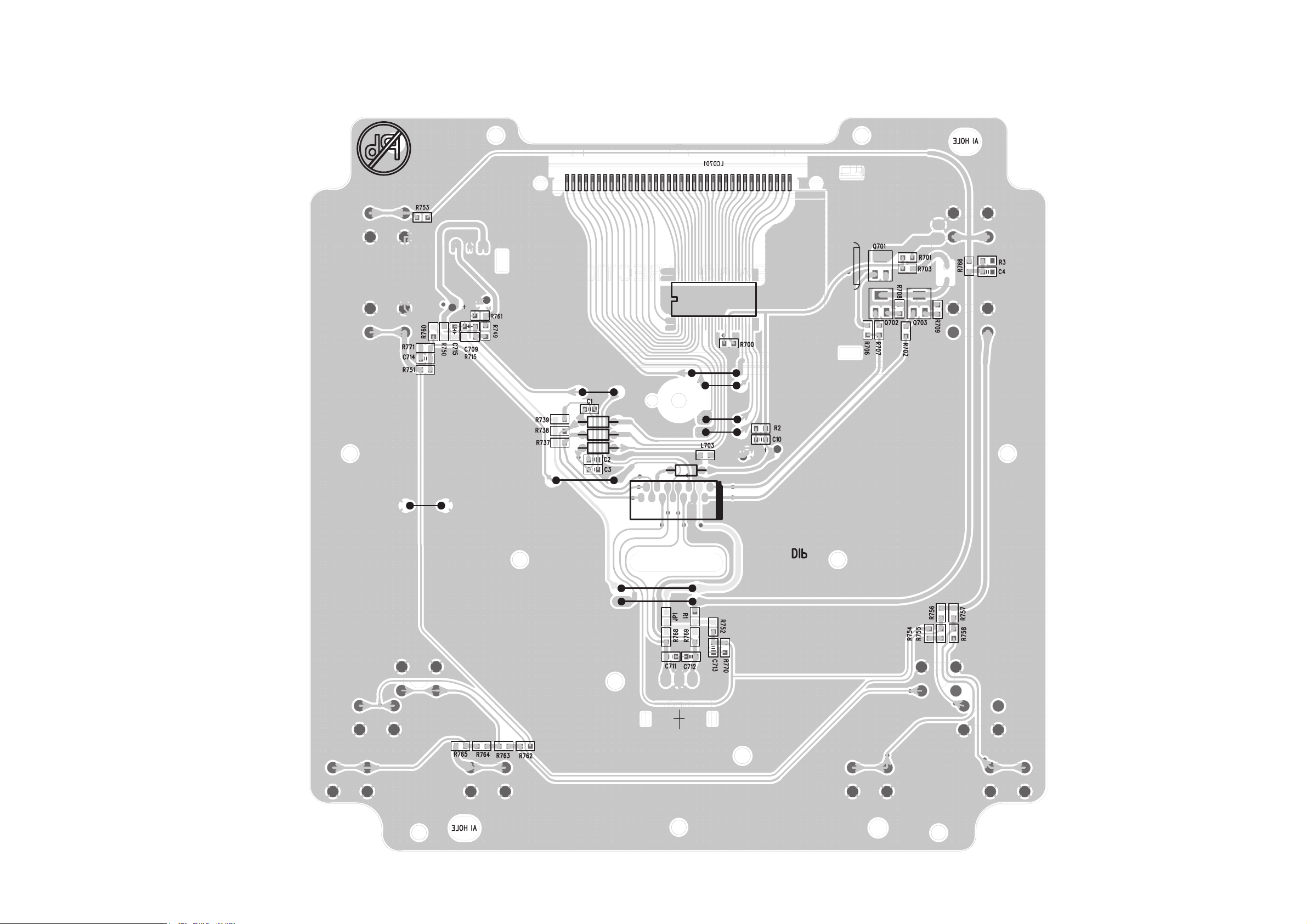
PCB LAYOUT - DISPLAY/KEY BOARD (BOTTOM VIEW)
IC701
6-3

6-4
CIRCUIT DIAGRAM - DISPLAY/KEY BOARD
6-4

7 - 1
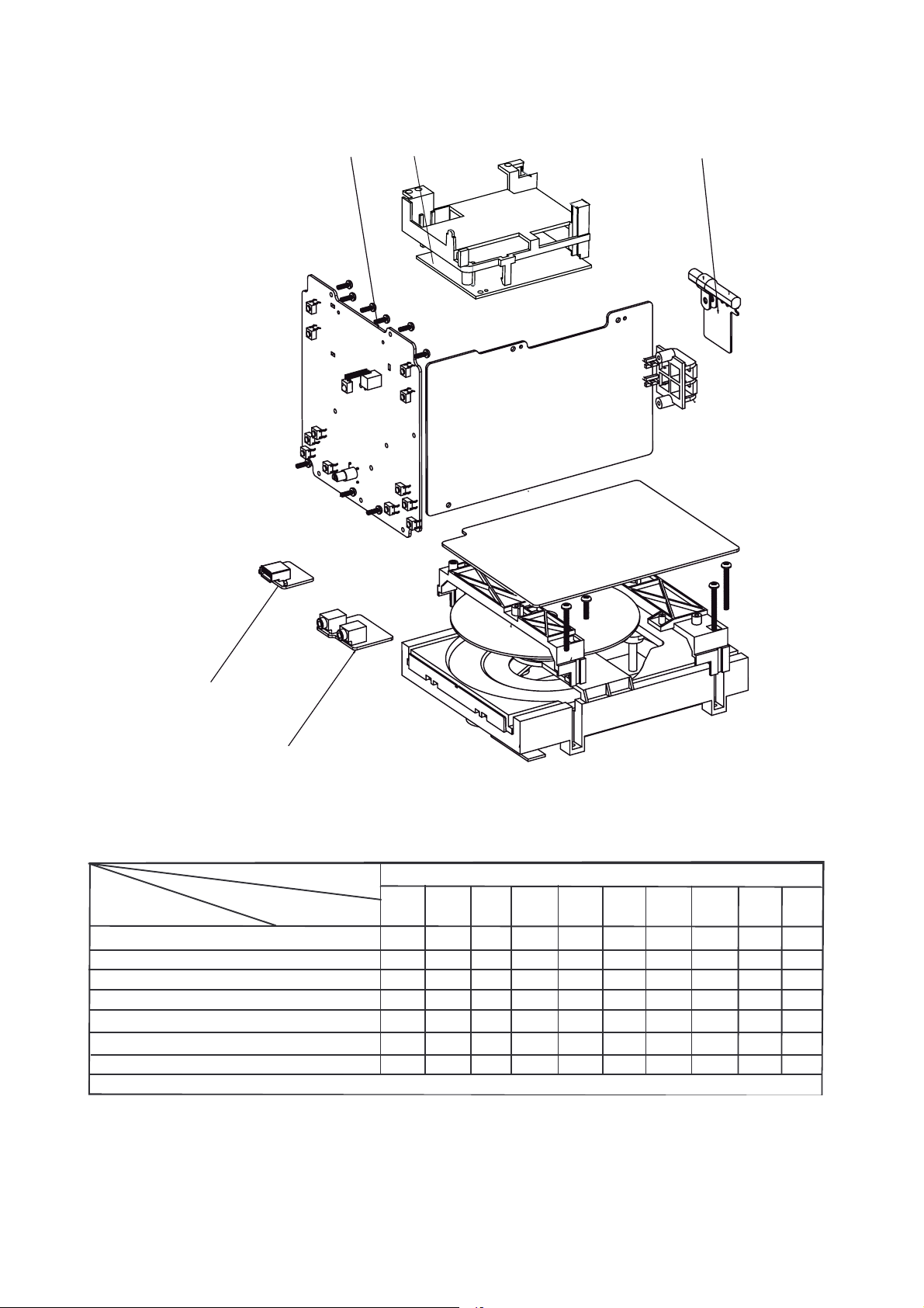
SET MECHANICAL EXPLODED VIEW
54
7 - 1
53
44
18
43
49
46
48
47
50
45
52
32
G
6
5
C
19
17
9
57
2
8
7
A
B
4
3
1
12
13
10
14
11
E
16
15
D
21
20

7 - 2 7 - 2
72
72
L
12NC
D
ti
L
12NC
D
4
996510021657
VOLUME KNOB
D4
996510010774
DIODE 1N4148 FDLL4148
IC501
996510010771
IC 7314(ANGUS)
1
Q
11
996510021653
DSC BUTTON
J40
996520035757
CARBON RES.100KR 1/6W J%
Q102
996500039268
TRANSISTOR KTC 8050C
18
996510016230
TOP CABINET
Q20
996510024762
TRANSISTOR KTC9014S
Q3
27
996510021654
SINGLE SPK BOX L/R
U1
996510021671
IC MA802AS
8
9965 00 5
CSS
(
)
55
996510012854
POWER LIGHT GUIDE
D102
996510001053
RECTIFIER DIODE RL201
TUNER PCB ASSY (ONLY FOR REFERENCE)
F
996510021664
MCM207 TUNER PCB
D5
996510010774
DIODE 1N4148 FDLL4148
X1
994000003208
CRYSTAL 32.768KHZ 12.5PF 10P
Q3
MECHANICAL & ACCESSORIES PARTS LIST ELECTRICAL PARTS LIST
oc.
escrip
on
oc.
escription
YSSA BCP NIAMYSSA BCP UCMTINU NIAM
D-V3.3-LA7111DL CI427500000499 102CI14-OD 9185N1 EDOID043110015699 1DTENIBAC TNORF486120015699 1
F022-OT IP6087S CI850100015699 202CI8414LLDF 8414N1 EDOID477010015699 01DTENIBAC RAER976120015699 2
)PID( 9PISF 7151D CI676120015699 103CI8414LLDF 8414N1 EDOID477010015699 2DTENIBAC MOTTOB956120015699 3
8554D CI265400015699 108CI8414LLDF 8414N1 EDOID477010015699 5DNOTTUB DC REWOP656120015699 5
01KCAJ8414LLDF 8414N1 EDOID477010015699 6DNOTTUB KCOLC ECRUOS666120015699 6
996510001054 6.5MM DC JACK (DJ32-2)
015699 7
SERP766120015699 01
%J W6/1 RK001.SER NOBRAC757530025699 04JNOTTUB CSD356120015699 11
S4109CTK ROTSISNART267420015699
17 996510021663 FUNCTION BUTTON BKT RIGHT Q18 996510011342 TRANSISTOR HIT562 PNP TO-92MOD Q207 996510003718 TRANSISTOR KTC-8550C
3Q
20 994000005786 CD MECHANISM DA11VF(SANYO) Q6 996510016572 TRANSISTOR KTC8050S SOT-23 ZD102 994000005722 ZENER DIODE 4V3 1/2W
25
47 996510025121 CASS KEY - FF
48 996510025122 CASS KEY - FB
49 996510025123 CASS KEY -REC
50 996510025124 CASS KEY - STOP
51 996510025125 DISPLAY LENS CON102 996510001071 USB JACK 4P ANGLE TYPE
58
!
A208AM CI176120015699 1UR/L XOB KPS ELGNIS456120015699 72
UROOD YEK ETTESSAC73261001569934
MAIN PCB ASSY
015699 1DREDLOH RAEG ROOD DC90410000049935
9945
3004N1 EDOID933110015699 301DMSINAHCEM KCED SSAC94410001569975
!
3004N1 EDOID933110015699 212DBCP BSU & .P.H & NIAM 702MCM401520015699B
FITCER3501000156995DMM1P P41 MM08 ELBAC CFF686120015699A509NOC
S4109CTK ROTSISNART267420015699
%J W6/1 R2.2.SER NOBRAC857530025699 9RLORTNOC ETOMER231520015699 62
DEMMARGORP S
T-HS-NB20C42TA CI367010015699 2UKCED .SSAC TEKCARB41152001569923
DEMMARGORP 040FV52TS CI166120015699 3
PFQL P821 3765M CI576120015699 4UROOD SSAC61152001569944
814-TSP KCAJ LANIMRET HSUP083000015699 103NOCTEKCARB - YEK SSAC62152001569925
14-OD 9185N1 EDOID043110
102LR EDOID REIFITCER350100015699101DRAEG ROOD DC1390000156
102LR EDOID REIFITCER350100015699 201DEDIUG THGIL REWOP45821001569955
8414LLDF 8414N1 EDOID477010015699 4DMM1P MM081 P61 ELBAC CFF186120015699FMDC
8414LLDF 8414N1 EDOID4770100156996DBCP SSAC601520015699G
102 996500039268 TRANSISTOR KTC-8050C
3QS4109CTK ROTSISNART26742001569902QTENIBAC POT03261001569981
SNART267420015699
HEADPHONE PCB ASSY
USB PCB ASSY
TUNER PCB ASSY
699 4D8414LLDF 8414N1 EDOID477010015699 2D)DRAOB DC( BCP UCM 702MCM201520015699A
4991X8414LLDF 8414N1 EDOID4770100156995DBCP RENUT 702MCM466120015699 F
ONLY FOR REFERENCE
C0508-CTK ROTSISNART862930005699 101Q%J W6/1 RK001.SER NOBRAC757530025699 93JNOTTUB MUBLA TE
S4109CTK ROTSISNART26742001569951QMROF EPAT 1004N1 EDOID66951001569906LNOTTUB POTS586120015699 21
B758CB ROTSISNART338210015699 71QEPYT DMS 0558S ROTSISNART323200015699 01QROOD DC71152001569931
S4109CTK ROTSISNART26742001569902QC0558-CTK ROTSISNART81730001569941QROOD BSU276120015699 41
C0508-CTK ROTSISNART862930005699 502QB758CB ROTSISNART338210015699 71QTFEL TKB NOTTUB NOITCNUF856120015699 61
S4109CTK ROTSI
S4109CTK ROTSISNART2674200156999QEDIUG THGIL REWOP458210015699 91
W2/1 1V9 EDOID RENEZ852930005699 102DZ32-TOS S0508CTK ROTSISNART275610015699 7QREDAOL YART DC178000015699 12
7V4XZB EDOID RENEZ433110015699302DZS4109CTK ROTSISNART2674200156999QA EPYT P02 ELBAC CFF767500000499 32
8414LLDF 8414N1 EDOID477010015699 2D8414N1 EDOID233110015699 601DA2.1 V51:CD V042-001:CA RETPADA821520015699
8414LLDF 8414N1 EDOID477010015
S4109CTK ROTSISNART26742001569920Q
S4109CTK ROTSISNART2674200156999Q
S-Y106-T808061KBS NAEB ETIRREF060100015699 2L8414LLDF 8414N1 EDOID477010015699 7DNOTTUB GNINUT776120
S-Y106-T808061KBS NAEB ETIRREF060100015699 3L8414LLDF 8414N1 EDOID477010015699 8DNOTTUB BBD286120015699 8
S-Y106-T808061KBS NAEB ETIRREF060100015699 4L8414LLDF 8414N1 EDOID477010015699 9DNOTTUB YALP266120015699 9
)CEK(277BTK ROTSISNART414100015699302Q 51QTEKCARB BSU657530025699 51
72DOS 2V8B-97XZB EDOID833110015699 105DZ%J W6/1 R2.2.SER NOBRAC857530025699 01RM17.0 EPYT EDV DROC LAVORPPA131520015699
KCAJ ENOHPDAEH OERETS654100000499109PH0274ACS CI376120015699 5UESUAP - YEK SSAC81152001569954
)NIP3( S91-5.3XKC ENOHPRAE370100015699 209PHMPP02-+ FP02 ZHM21 LAT'X675610015699 2YYALP - YEK SSAC91152001569964
)NFQ( P02 MG-01A-0374IS CI556120015699 1U102LR EDOID REI
P01- FP5.21 ZHK867.23 LATSYRC802300000

7 - 3 7 - 3
73
73
R741
996510021674
CARBON RES.100R 1/6W J%
SW703
996500039269
TACT SWITCH
SW710
996500039269
TACT SWITCH
ELECTRICAL PARTS LIST
Loc. 12NC Description
DISPLAY/KEY PCB ASSY
EN701 996510001059 ENCODER EC121102X2B-HA1-082
IC701 996510001064 IC ET8861S LCD DRIVER
LCD701 996510021695 LCD DISPLAY
Q15 996510024762 TRANSISTOR TRANSISTOR KTC9014S
Q20 996510024762 TRANSISTOR TRANSISTOR KTC9014S
Q3 996510024762 TRANSISTOR TRANSISTOR KTC9014S
R742 996510021674 CARBON RES. 100R 1/6W J%
R743 996510021674 CARBON RES. 100R 1/6W J%
R808 996510021669 CARBON RES. 47R 1/6W J%
RS701 996510011311 INFRARED RECEIVER RIGHT ANGLE
SW701 996500039269 TACT SWITCH
SW702 996500039269 TACT SWITCH
SW703 996500039269 TACT SWITCH
SW704 996500039269 TACT SWITCH
SW705 996500039269 TACT SWITCH
SW706 996500039269 TACT SWITCH
SW707 996500039269 TACT SWITCH
SW708 996500039269 TACT SWITCH
SW709 996500039269 TACT SWITCH
SW710 996500039269 TACT SWITCH
SW711 996500039269 TACT SWITCH
SW712 996500039269 TACT SWITCH
Note: Only these parts mentioned in the list are
normal service parts.

8 - 1
REVISION LIST
1.0 Manual 3141 785 33920
Initial Service Manual released.
1.1 Manual 3141 785 33921
In this version,
Mechanical Partslist updated.
996510024762 TRANSISTOR KTC9014S (was 996510012793 TRANSISTOR BC847B)
 Loading...