

Micro System
MCM205/12
TABLE OF CONTENTS
Page
Location of PCBs ..................................................................1-2
Specifi cations .......................................................................1-3
Measurement Setup .............................................................1-4
Service Aids, Safety Instruction, etc .....................................1-5
CD Playability Check ..................................................1-6 to 1-7
Software Version Checking .....................................................2
Set Wiring & Block Diagram ....................................................3
Main & Tuner & Headphone Boards ........................................4
MCU & USB Board .................................................................. 5
Display & Key Board................................................................6
Set Mechanical Exploded View & Parts List ............................7
Revision List ............................................................................8
©
Copyright 2009 Philips Consumer Electronics B.V. Eindhoven, The Netherlands
All rights reserved. No part of this publication may be reproduced, stored in a retrieval system or
transmitted, in any form or by any means, electronic, mechanical, photocopying, or otherwise without
the prior permission of Philips.
Published by SL 0914 Service Audio Printed in The Netherlands Subject to modification
Version 1.2
CLASS 1
LASER PRODUCT
© 3141 785 33912
PCBS LOCATION
1-2
DISPLAY & KEY BOARD
TUNER BOARD
MAIN BOARD
MCU BOARD
USB BOARD
VERSION VARIATIONS
Board in used:
MAIN BOARD
MCU BOARD
USB JACK BOARD
DISPLAY & KEY BOARD
TUNER BOARD
HEADPHONE BOARD
* TIPS : C -- Component Lever Repair.
M -- Module Lever Repair
-- Used
x
HEADPHONE BOARD
Type /Versions:
Service policy
/12 /05
C
C/M
C
C
M
C
/37
MCM205
/55
16/85/
89/

Specifications
1-3
Amplier
Rated Output Power 2X5W RMS
Frequency Response 60 - 16kHz, ±3dB
Signal to Noise Ratio >62dB
Disc
Laser Type Semiconductor
Disc Diameter 12cm/8cm
Support Disc CD-DA, CD-R,
CD-RW, MP3-CD,
WMA-CD
Audio DAC 24Bits / 44.1kHz
Total Harmonic
Distortion
Frequency Response 60Hz -16kHz
S/N Ratio >62dBA
<1%
Tuner
Tuning Range FM: 87.5 - 108MHz;
MW: 531 - 1602kHz
Tuning grid 50 kHz (FM); 9 kHz
(MW)
Total Harmonic
Distortion
Signal to Noise
Ratio
<3%
>50 dB
Speakers
Speaker Impedance 4ohm
General information-Specs
Switching mode power
supply
Operation Power
Consumption
Standby Power
Consumption
Eco Standby Power
Consumption
Dimensions
- Main Unit
(W x H x D)
- Speaker Box
(W x H x D)
Weight
- With Packing
- Main Unit
- Speaker Box
Model: GFP181T1512-1 or
GFP181DA-1512-1,
Input: AC100240V~, 50/60Hz,
0.35A Output:
DC15V, 1.2A
26 W
<4 W
<1 W
152 x232 x 222mm
146 x 232 x 140mm
5.20 kg
1.64 kg
2.20 kg
Supported MP3 disc formats
ISO9660, Joliet•
Maximum title number: 512 (depending •
on le name length)
Maximum album number: 255•
Supported sampling frequencies: 32 kHz, •
44.1kHz, 48 kHz
Supported Bit-rates: 32~256 (kbps), •
variable bit rates
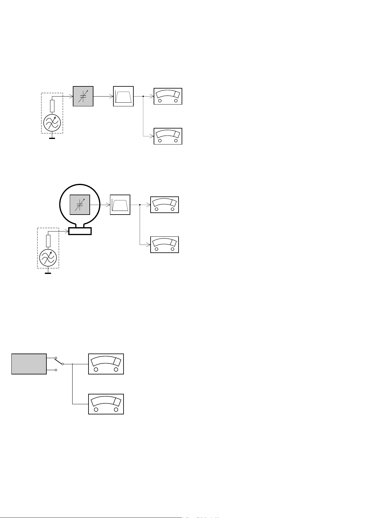
MEASUREMENT SETUP
Tuner FM
1-4
Bandpass
LF Voltmeter
e.g. PM2534
RF Generator
e.g. PM5326
DUT
250Hz-15kHz
e.g. 7122 707 48001
Ri=50
S/N and distortion meter
e.g. Sound Technology ST1700B
Use a bandpass filter to eliminate hum (50Hz, 100Hz) and disturbance from the pilottone (19kHz, 38kHz).
Tuner AM (MW,LW)
RF Generator
e.g. PM5326
Ri=50
DUT
Frame aerial
e.g. 7122 707 89001
Bandpass
250Hz-15kHz
e.g. 7122 707 48001
LF Voltmeter
e.g. PM2534
S/N and distortion meter
e.g. Sound Technology ST1700B
To avoid atmospheric interference all AM-measurements have to be carried out in a Faraday´s cage.
Use a bandpass filter (or at least a high pass filter with 250Hz) to eliminate hum (50Hz, 100Hz).
CD
Use Audio Signal Disc
DUT
L
R
SBC429 4822 397 30184
S/N and distortion meter
e.g. Sound Technology ST1700B
LEVEL METER
e.g. Sennheiser UPM550
with FF-filter
(replaces test disc 3)
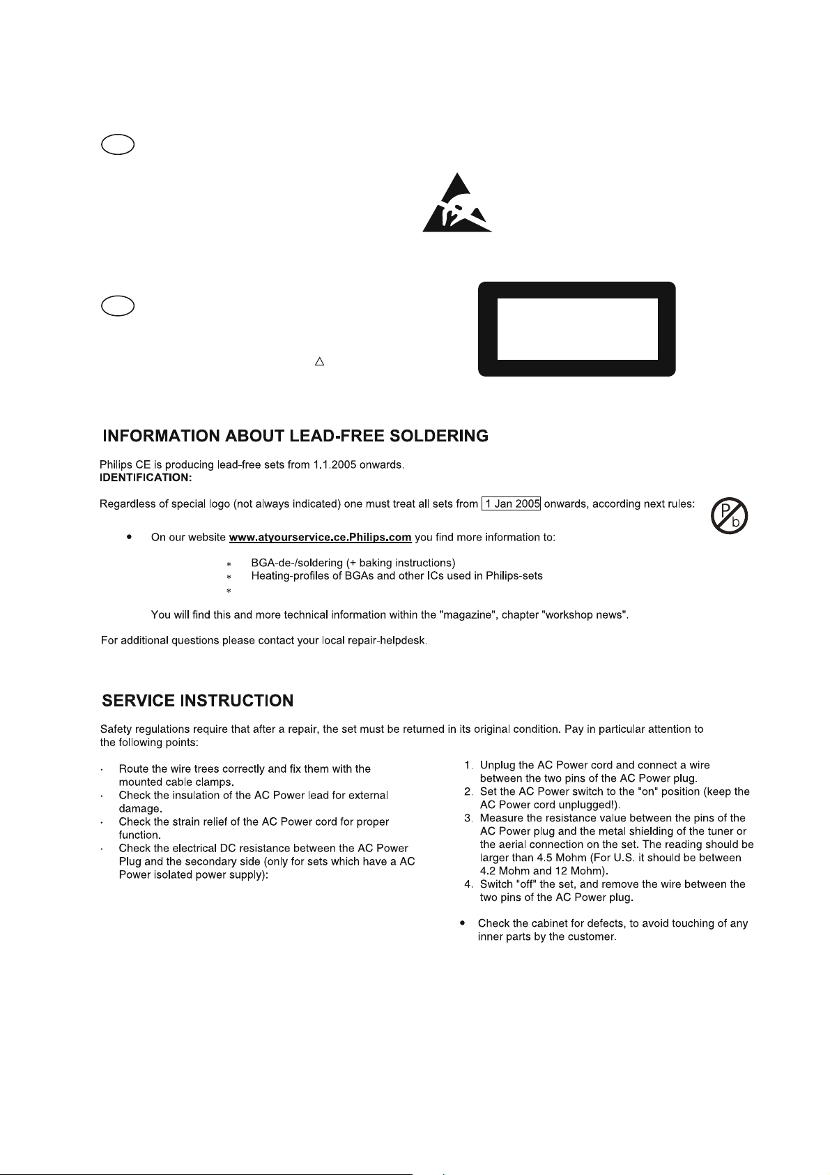
SERVICE AIDS
1-5
GB
All ICs and many other semi-conductors are
susceptible to electrostatic discharges (ESD).
Careless handling during repair can reduce life
drastically.
When repairing, make sure thatyouare
connected with the same potential as the mass
of the set viaawrist wrap with resistance.
Keep components and tools also at this
potential.
WARNING
GB
Safety regulations require that the set be restored to its original
condition and that parts which are identical with those specified,
be used
Safety components are marked by the symbol
!
.
ESD
CLASS 1
LASER PRODUCT
Lead free
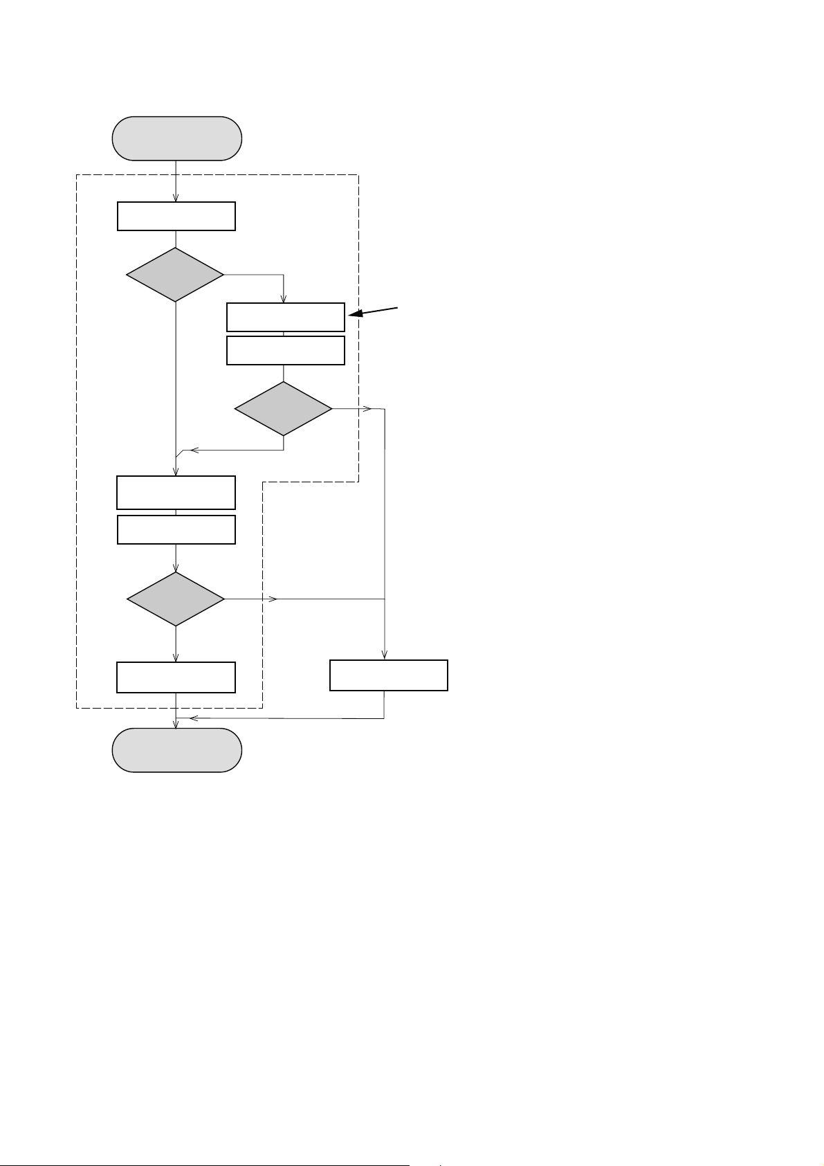
INSTRUCTIONS ON CD PLAYABILITY
Customer complaint
"CD related problem"
Set remains closed!
check playability
1 - 6
playability
ok ?
Y
Play a CD
for at least 10 minutes
check playability
playability
ok ?
Y
N
"fast" lens cleaning
check playability
playability
ok ?
N
For flap loaders (= access to CD drive possible)
cleaning method
N
Y
is recommended
add Info for customer
"SET OK"
return set
- For description - see following pages
Exchange CDM
INSTRUCTIONS ON CD PLAYABILITY
1 - 7
PLAYABILITY CHECK
For sets which are compatible with CD-RW discs
use CD-RW Printed Audio Disc ....................7104 099 96611
TR 3 (Fingerprint)
TR 8 (600µ Black dot) maximum at 01:00
• playback of these two tracks without audible disturbance
playing time for: Fingerprint
Black dot from 00:50 to 01:10
• jump forward/backward (search) within a reasonable time
For all other sets
use CD-DA SBC 444A..................................4822 397 30245
TR 14 (600µ Black dot) maximum at 01:15
TR 19 (Fingerprint)
TR 10 (1000µ wedge)
• playback of all these tracks without audible disturbance
playing time for: 1000µ wedge 10seconds
Fingerprint 10seconds
Black dot from 01:05 to 01:25
• jump forward/backward (search) within a reasonable time
10seconds
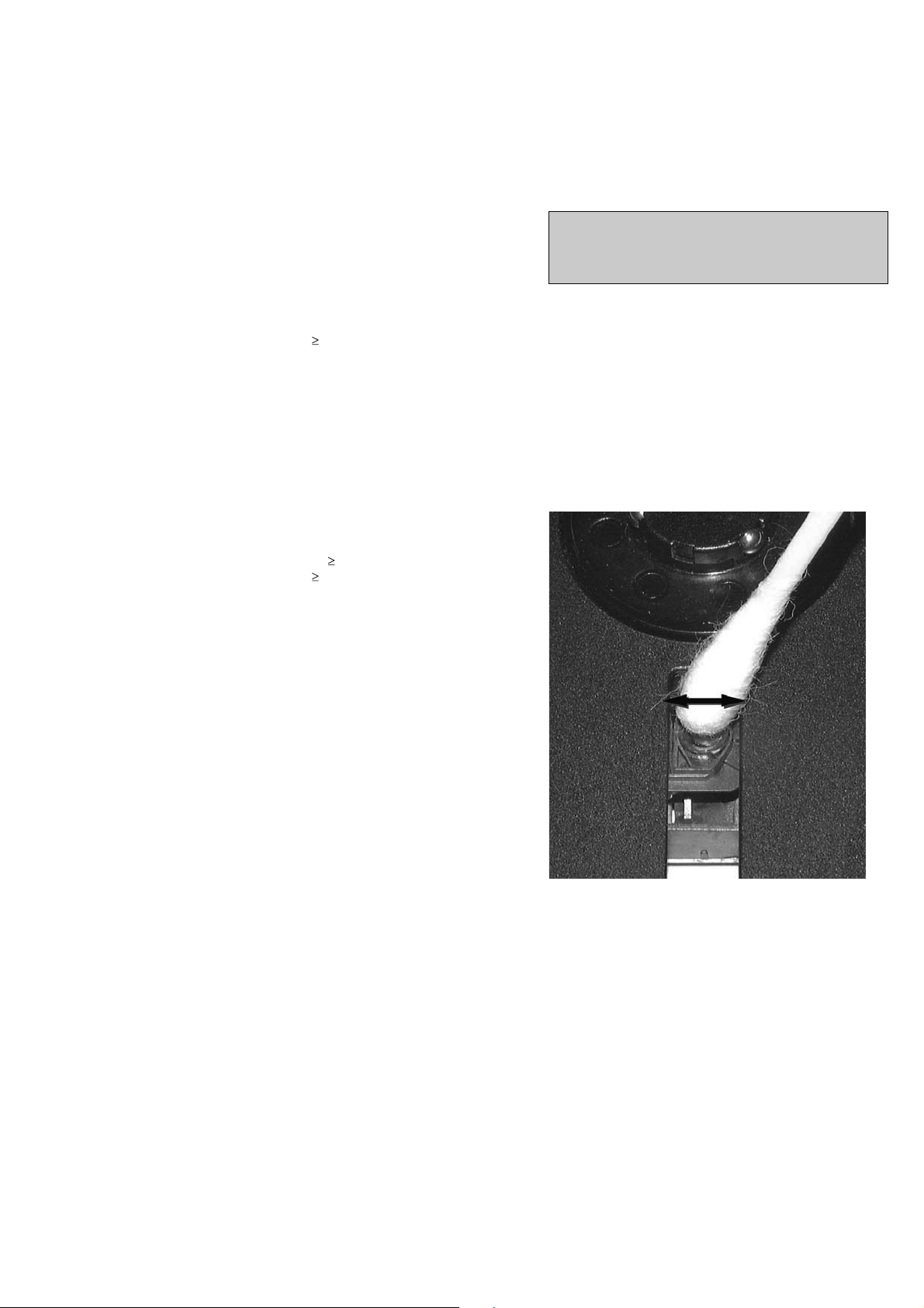
LIQUID LENS CLEANING
Before touching the lens it is advised to clean the
surface of the lens by blowing clean air over it.
This to avoid that little particles make scratches on
the lens.
Because the material of the lens is synthetic and coated
with a special anti-reflectivity layer, cleaning must be done
with a non-aggressive cleaning fluid. It is advised to use
“Cleaning Solvent
The actuator is a very precise mechanical component and
may not be damaged in order to guarantee its full function.
Clean the lens gently (don’t press too hard) with a soft and
clean cotton bud moistened with the special lens cleaner.
The direction of cleaning must be in the way as indicated in
the picture below.
CUSTOMER INFORMATION
It is proposed to add an addendum sheet to the set which
informs the customer that the set has been checked
carefully - but no fault was found.
The problem was obviously caused by a scratched, dirty or
copy-protected CD. In case problems remain, the customer
is requested to contact the workshop directly.
The lens cleaning (method ) should be mentioned in the
addendum sheet.
The final wording in national language as well as the printing
is under responsibility of the Regional Service Organizations.

SERVICE TEST PROGRAM
2-1
2-1
How to read software version,
1. Plug A/C to power on and under NO DISC status, press and hold PLAY and DBB buttons for 5 seconds,
LCD Display shows existing CD software version "CD - V029" and MCU software version “MCU - 013”.
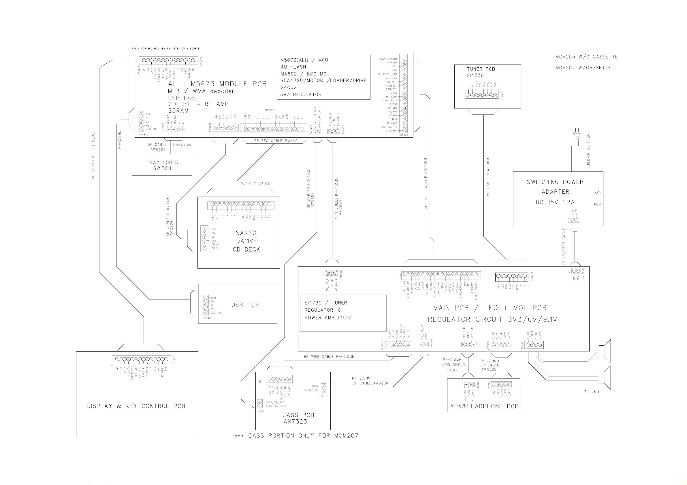
3-1
3-1
SET BLOCK & WIRING DIAGRAM

MAIN & TUNER &HEAD-
PHONE BOARD
TABLE OF CONTENTS
Main Board Layout Top View ........................................... 5-2
Main Board Layout Bottom View ..................................... 5-3
Tuner Board Layout Diagram ........................................... 5-4
Headphone Board Layout Diagram ................................. 5-5
Circuit Diagram ................................................................ 5-6
4-1 4-1

4-2 4-2
PCB LAYOUT - MAIN BOARD (TOP VIEW)

4-3 4-3
PCB LAYOUT - MAIN BOARD (BOTTOM VIEW)

4-4
4-4
PCB LAYOUT - TUNER BOARD (ONLY FOR REFERENCE, MODULE SWAP )

4-5
4-5
LAYOUT DIAGRAM - HEADPHONE BOARD

4-6
4-6
CIRCUIT DIAGRAM - MAIN & TUNER & HP BOARD

5-1 5-1
MCU & USB BOARD
TABLE OF CONTENTS
MCU Board Layout Top View ..........................................5-2
MCU Board Layout Bottom View .....................................5-3
USB Jack Board Layout Diagram .....................................5-4
Circuit Diagram .................................................................5-5

5-2 5-2
PCB LAYOUT - MCU BOARD (TOP VIEW)

5-3
PCB LAYOUT - MCU BOARD (BOTTOM VIEW)
5-3

LAYOUT DIAGRAM - USB BOARD
5-4
5-4

5-5
CIRCUIT DIAGRAM - MCU & USB BOARD
5-5

DISPLAY/KEY BOARD
TABLE OF CONTENTS
Layout Top View ............................................................... 6-2
Layout Bottom View ..........................................................6-3
Circuit Diagram ................................................................. 6-4
6-1
6-1

6-2
PCB LAYOUT - DISPLAY/KEY BOARD (TOP VIEW)
6-2

6-3
PCB LAYOUT - DISPLAY/KEY BOARD (BOTTOM VIEW)
IC701
6-3

6-4
CIRCUIT DIAGRAM - DISPLAY/KEY BOARD
6-4

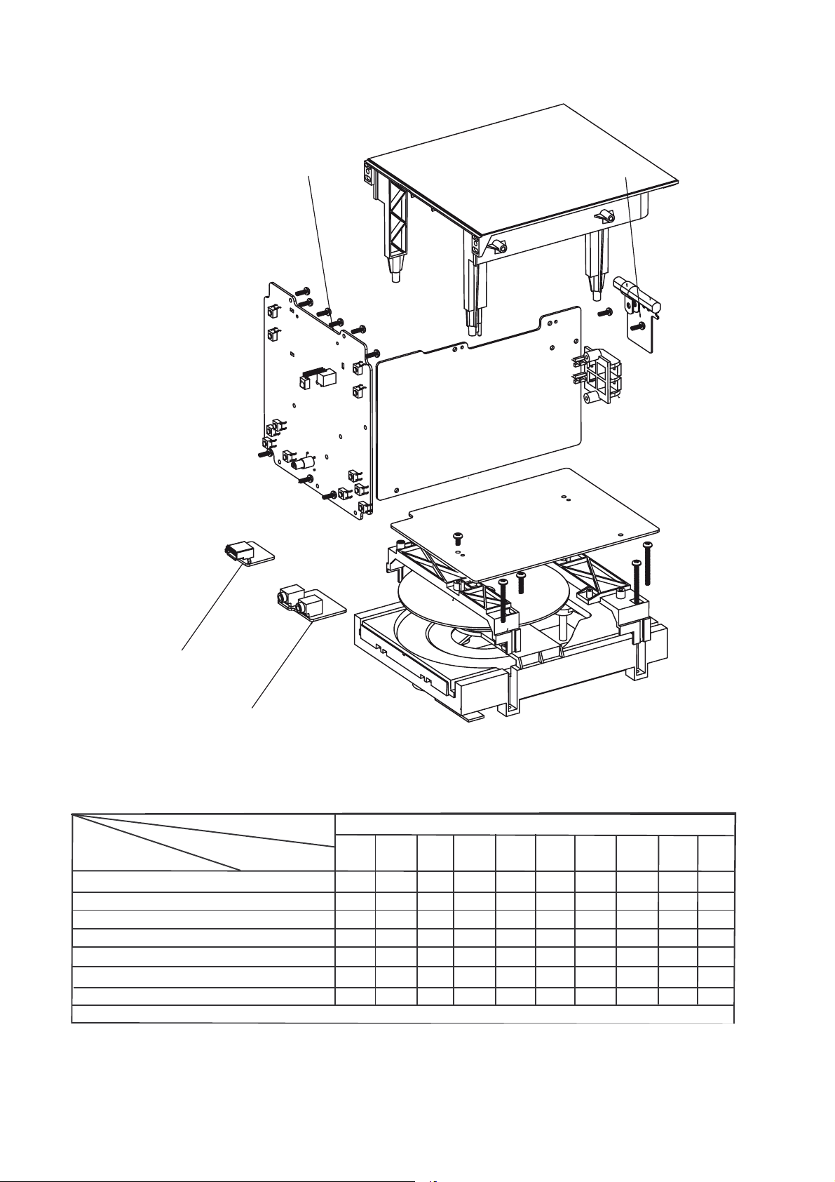
7 - 1
SET MECHANICAL EXPLODED VIEW
7 - 1
18
C
F
6
5
19
17
9
8
2
7
4
3
1
12
13
10
14
11
E
16
15
D
A
B
21
20

7 - 2
1
996510021684
FRONT CABINET
J40
996520035757
CARBON RES.100KR 1/6W J%
L4
996510001060
FERRITE BEAN SBK160808T 601Y S
8
9965 00 68
U O
Q 05
996500039 68
S S O C 8050C
12
99651002168
STOP BUTTON
ZD102
994000005722
ZENER DIODE 4V3 1/2W
19
996
100128
4
POWER LIGHT GUIDE
U
996
100216
3
IC SCA4
20
26
996510021665
REMOTE CONTROL
R741
996510021674
CARBON RES
100R
1/6W J%
ELECTRICAL PARTS LIST
S
C
D212
996510011339
DIODE
1N4003
SW706
996500039269
TACT SWITCH
(
)
D5
996510010774
DIODE 1N4148 FDLL4148
IC301
996510021676
IC D1517 FSIP9 (DIP)
1
MECHANICAL & ACCESSORIES PARTS LIST ELECTRICAL PARTS LIST
Loc. 12NC Description Loc. 12NC Description
7 - 2
INU
NIAM
TENIBACMOTTOB9561200156993
BONKEMULOV7561200156994
2
861200156998
5
16 996510021658 FUNCTION BUTTON BKT LEFT U2 996510010763 IC AT24C02BN-SH-T
17 996510021663 FUNCTION BUTTON BKT RIGHT U3 996510021661 IC ST25VF040 PROGRAMMED
821
001569981
5
2
21 996510000871 CD TRAY LOADER
22 996510021686 FFC CABLE 80MM 14P P1MM
23 994000005767 20 PINS FFC CABLE TYPE A
24 996510021681 FFC CABLE 16P 180MM P1MM
25
27 996510021654 SINGLE SPK BOX L/R R742 996510021674 CARBON RES. 100R 1/6W J%
F 996510021664 MCM207 TUNER PCB
A 996510021678 MCM207 MCU PCB
!
5
817530015699
TIW
C
S
TEN
IBACPOT94
M
NAHCEMDC6875000004990
SI
V11
AD
OTPADAGNIH
AR
)OYNAS(F
01Q
41Q
5
1Q
01RROODDC86612001569931
1UTEKCARBBSU65753002569951
5
Y
USB PCB ASSY
MAIN PCB ASSY
CON301 996510000380 PUSH TERMINAL JACK PST-418 RS701 996510011311 INFRARED RECEIVER RIGHT ANGLE
D103 996510011339 DIODE 1N4003
1D
Loc. 12NC Description
MCU PCB ASSY
5D
D
1
1D
0
2D
4D
8D
9D
J39 996520035757 CARBON RES.100KR 1/6W J% L3 996510001060 FERRITE BEAN SBK160808T-601Y-S HP902 996510001073 EARPHONE CKX3.5-19S (3PI
9
9
69
9
97D
699
99
701001569
77010015
4
015699
77010
0100156995D
100156996D
1569
010
015
0100
156
OID4770
185N
1EDOID04311001569
EDOID47
EDOID4
4N1
EDOID
EDOID477
8414N1
414N1ED
F8414N1EDOID4770100
4N1EDOID477
8414N1EDOID477
8414LLDF8414N1
8414
LLDF841
LLDF
LLDF8
4LLD
414LLDF841
14LLDF
6
D8414LLDF8414N1
102CI
103CI8414
105CI8414
108CI841
01KCAJ8
996510001054 6.5MM DC JACK (DJ32-2)
2L84
YS
SABCPUCMT
1R
0
1.SERNOBRAC75753002569904JTENIBACTNORF4861200156991
K0
043
11001569906LTENIBACRAER9761200156992
699
15
AR
T
23200015699
3
674
20015
699
01569981QNOTTUBGNINUT7761200156997
10
674
20015
699Q3
674
20015
699Q20
56
100156996QNOTTUBMUBLATESERP76612001569901
20015
699Q9
9
256999RROODBSU27612001569941
9
5
6992
56991D
69960
992D
9212D
994D
56
6995D14-OD9
699
9202CI
99
9
699
674
00
7
015
75610
6
1001
0431
50100015699201D
110
015
100156
93
001569
311
01001
477
015699
35
0100
10015
4770
010015
477
27500000499
8
001569
5010
1200156
177
01001569
26
00015699
54
0100015
06
AR
T2
ER3
ER
I676
5N1EDOID
T
SISNART3232000
OT
SISNART33821001569971QNOTTUBKCOLCECRUOS6661200156996
OT
SISNART2431
SISNART27
OTSISNART2756100156997QNOTTUBCSD35612001569911
SN
NOBRAC85753
A
208AMCI17612001569
S
7
1LAT'X
M
2
KCAJBSU170100015699201NOCV042-001C
85N1EDOID
N
14
1EDOID233
EDOID4770
N1
1E
DOID
14N1EDOID
EIFITC
14N1EDOID
14N1EDOID
11DLCI4
71
6087SCI
7151DC
A(
4137CI
8554DCI
-OD
918
4
0558
SRO
558SROTSISN
R KTC9014SOTSISNART2
BR
HR
R KTC9014SOTSISNART2
R KTC9014SOTSISNART2
R KTC9014SOTSI
2.SERNOBRAC85753002569
2.2.SER
P
8213765MCI5761200156994U
ZH
P02
A
LGN
P4
91
EDOIDREIFITC
4
8
LDF8
414
3004N
84
DOIDR
84
84
3.3-LA
D-V
F02
2-OTIP
9
PISF
DIP
)SUGN
SNAEBETIRREF
TDMS0
B
758C
265TI
508CTKROT
0508CTKR
/1R2.
PFQL
102LR
84
14L
84
14LLDF
10
2LRE
841
4LLDF
84
14LLDF
61KB
DOM29-OTPNP
32-TOSS0
32-TOSS
106-T8080
S-Y
PNIAM
C
4L%JW6/
101Q1
01QEPYTDMS
5
1QEPY
71QNOTTUBDCREWOP6561200156995
02Q
02Q
0
2QNOTTUBBBD
2QNOTTUBYALP2661200156999
102DZ%JW6
02DZ%JW6/1R
3
105DZDEMMARGORP
DISPLAY/KEY PCB ASSY
107NEMPP02-+F
IC701 996510001064 IC ET8861S LCD DRIVER
LCD701 996510021695 LCD DISPLAY
Q15 996510024762 TRANSISTOR KTC9014S
Q20 996510024762 TRANSISTOR KTC9014S
R743 996510021674 CARBON RES. 100R 1/6W J%
R808 996510021669 CARBON RES. 47R 1/6W J%
107WS14-OD
207WS
W703 996500039269 TA
407WS
S
6
07WS
707WS
807W
S
907WS
117WS
17WS
2
HEADPHONE PCB ASSY
109PH
S
Y
AB
S
6010
0015
699
9
5699
3000
862
SN
T8
005
01569
015
0
00056
0
0156
0015
000
0056
000569
005699
62930
674
20015
210
674
20015
14100
9300
300
20015
674
20015
674
293
100
311
1
0001
24762
6293000569
29
300056
93
300056
29
930005699017WS
62
300056
29
30
SI
AR
ISNART338
SI
AR
SN
T4
862
AR
T2
ENEZ
AR
TSWITCH
TCAT9629
ISNART
SN
EDOID83
SI
SN
817
4331
950
T
96293
962930
9
962930005699
6992
699
9
699
6993
0569
95
970
1569
699Q3
699Q9
99
15699
99
5699
6993QEPYTE
9
569
9
9
9
99507W
9
9
99
99
9
SNA
EBETIRREF0
R KTC9014SOTSISNART2
BROTS
R KTC9014SOTSISNART2
TKROT
KROTSISNART
KROTS
R KTC9014SOTSISNART2
R KTC9014SOTSI
V9
EDOIDRENEZ85
B
EDOIDR
8B-97XZB
1
121CEREDOCNE
R KTC9014SO
T
.
HCTIWSTCAT
HCTIWSTCAT
HCTIWSTCAT
HCTIWSTCAT96
HCTIWSTCAT
HCTIWSTCAT962
HCTIWSTCAT96293000569
HCTIWSTCAT96
HCTIWSTCAT9
HCTIWSTCAT96
H
CTIWS
080
61KB
05
C
08-CTKROTSISNART
050
C
8-CTKROT
B
758C
277B
)CEK(
0
C
508-CT
558-CT
C0
W2/
11
7V
4XZ
72DOS2V
X20
OHPDAEHOERETS65410000049
KCAJEN
S-Y106-T8
280-1AH-B2
N)

7 - 3
Loc.12NC
Description
ELECTRICAL PARTS LIST
Loc. 12NC Description
TUNER PCB ASSY (ONLY FOR REFERENCE)
D2 996510010774 DIODE 1N4148 FDLL4148
D4 996510010774 DIODE 1N4148 FDLL4148
Q20 996510024762 TRANSISTOR KTC9014S
Q9 996510024762 TRANSISTOR KTC9014S
U1 996510021655 IC SI4730-A10-GM 20P (QFN)
X1 994000003208 CRYSTAL 32.768KHZ 12.5PF -10P
7 - 3

8 - 1
REVISION LIST
1.0 Manual 3141 785 33910
Initial Service Manual released.
1.1 Manual 3141 785 33911
In this version,
P7-2 Mechanical Partslist updated.
25 996510035718 SWITCHING ADAPTOR AC100-240V (was 996510021683 SWITCHING
ADAPTOR AC100-240V )
1.2 Manual 3141 785 33912
In this version,
P7-2 Mechanical Partslist updated.
996510024762 TRANSISTOR KTC9014S (was 996510012793 TRANSISTOR BC847B)
 Loading...