

Philips MCD395/12, MCD395/05, MCD395/98, MCD395/61, MCD395/55 Service Manual
...
Version 1.3
MCD395/12/58
3141 785 32623
DVD Micro theatre
Published by SL 1107 Service Audio Subject to modification
©
Copyright 2011 Philips Consumer Electronics B.V. Eindhoven, The Netherlands
All rights reserved. No part of this publication may be reproduced, stored in a retrieval
system or transmitted, in any form or by any means, electronic, mechanical, photocopying,
or otherwise without the prior permission of Philips.
Block diagram ................................................................................5-1
Wiring diagram .............................................................................6-1
LCD & Key Board
circuit diagram ..................................................................7-1...7-2
layout diagram ..........................................................................7-3
Main Board
circuit diagram ..................................................................9-1...9-5
layout diagram ..................................................................9-6...9-7
HP & AUX & USB Jack Board
circuit diagram ..................................................................9-8...9-9
layout diagram .................................................................9-8...9-9
DVD MPEG Board
circuit diagram. .............................................................10-1...10-8
layout diagram ............................................................10-9...10-10
Exploded view diagram ...............................................................11-1
Mechanical partslist .....................................................................11-2
Electrical partslist...............................................................12-1...12-2
TABLE OF CONTENTS
PCBs location & Version Variations...............................................1-1
Technical specification ...................................................................1-2
Service measurement setup .........................................................1-3
Service aids ..................................................................................1-4
Instructions on CD playability ...............................................2-1...2-2
Software version check .................................................................4-1
Rectifier Board
circuit diagram ..........................................................................8-1
layout diagram ..........................................................................8-1
Power AMP Board
circuit diagram ..................................................................8-3...8-4
layout diagram ..........................................................................8-5
Revision list..................................................................................13-1

LCD & KEY BOARD
RECTIFIER BOARD
SERVO BOARD
(DVD MPEG BOARD)
TUNER MODULE
MAIN BOARD
POWER AMP BOARD
/12 /58
xxniRDC/nixuA
Line Out
Video Out
Subwoofer Out
Digital Out
Karaoke Features
Voltage Selector
ECO Power Standby (LCD Display Off)
USB Direct
Type /Versions: MCD395
Features
in used:
/05
VERSION VARIATIONS
Type /Versions:
Board in used:
MCD395
Service policy
MAIN BOARD
SERVO(MPEG) BOARD
USB JACK BOARD
RECTIFIER (POWER) BOARD
* TIPS : C -- Component Lever Repair.
M -- Module Lever Repair
-- Used
C
M
/12 /05
/55
89/16/85/
Feature diffrence
C
M
LCD & KEY BOARD
C
C
C
C
C
C
TUNER MODULE
M
M
x
xx
xx
xx
xx
xx
xx
1 - 1
PCBS LOCATION
POWER AMP BOARD
CC

AMPLIFIER
Output power ....................................... 2 x 50 W RMS
Signal-to-noise ratio ....................................... ≥ 60 dBA
Frequency response ......... 63 – 16000 Hz, ± 3 dB
Input sensitivity AUX ....................... 0.5 V (max. 2 V)
Impedance loudspeakers ......................................... 4 Ω
Impedance headphones .................... 32 Ω -1000 Ω
DVD PLAYER
Laser Type ................................................ Semiconductor
Disc Diameter .............................................. 12cm / 8cm
Video Decoding ........................... MPEG-2 / MPEG-1
Video DAC ................................................................ 10 Bits
Signal System ............................................... PAL / NTSC
Video Format ..................................................... 4:3 / 16:9
Video S/N ........................................... 56 dB (minimum)
Composite Video Output ................ 1.0 Vp-p, 75 Ω
S-Video Output ............................. Y - 1.0 Vp-p, 75 Ω
........................................................... C - 0.286 Vp-p, 75 Ω
Audio DAC .......................................... 24 Bits / 96 kHz
Frequency Response .... 4 Hz - 20 kHz (44.1kHz)
...................................................... 4 Hz - 22 kHz (48kHz)
...................................................... 4 Hz - 44 kHz (96kHz)
Digital Output .........................................................................
....... SPDIF (Sony Philips digital interface) Coaxial
Number of programmable tracks ......................... 16
Signal-to-noise ratio ....................................... ≥ 65 dBA
Channel separation .......................... ≥ 40 dB (1 kHz)
Total harmonic distor tion ............... < 0.1% (1 kHz)
TUNER
FM wave range ................................... 87.5 – 108 MHz
Sensitivity at 75 Ω
– mono, 26 dB signal-to-noise ratio ............ 2.8 µV
– stereo, 46 dB signal-to-noise ratio ........ 61.4 µV
Selectivity ................................................................. ≥ 28 dB
Total harmonic distor tion ..................................... ≤ 5%
Frequency response ............ 63 – 5500 Hz (-6 dB)
Signal-to-noise-ratio ...................................... ≥ 50 dBA
USB PLAYER
USB ......................................................................... V2.0/ V1.1
...................................... suppor t MP3/WMA/JPEG files
Number of albums/ folders ................ maximum 99
Number of tracks/titles ...................... maximum 500
SPEAKERS
2-way bass reflex system
GENERAL INFORMATION
AC Power ..................................... 220 – 230 V / 50 Hz
Standby power consumption ............................ ≤ 7W
Eco power Standby................................................ < 1W
Dimensions
Main Unit(w x h x d) ........152 x 228 x 285 (mm)
Speakers (w x h x d) ..........................................................
...................................................... 152 x 228 x 257 (mm)
Weight
With Packing ............................................................ 9.58 kg
Main Unit ................................................................... 3.80 kg
Speaker box ............................................................. 4.22 kg
Specifications and external appearance are
subject to change without notice.
TECHNICAL SPECIFICATIONS
1 - 2
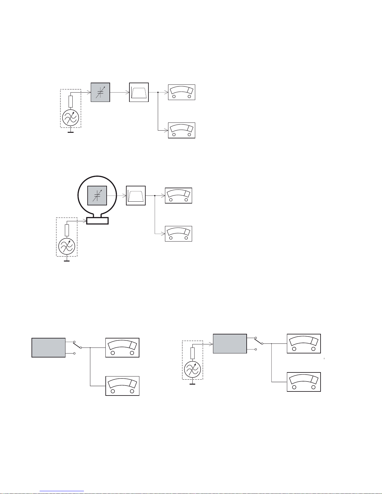
1-3
LF Generator
e.g. PM5110
Recorder
Use Universal Test Cassette CrO2 SBC419 4822 397 30069
LEVEL METER
e.g. Sennheiser UPM550
with FF-filter
S/N and distortion met
e
e.g. Sound Technology ST170
L
R
DUT
or Universal Test Cassette
Fe SBC420 4822 397 30071
LEVEL METER
e.g. Sennheiser UPM550
-
S/N and distortion meter
e.g. Sound Technology ST1700B
L
R
DUT
CD
Use Audio Signal Disc
(replaces test disc 3)
SBC429 4822 397 30184
Bandpass
250Hz-15kHz
e.g. 7122 707 48001
LF Voltmeter
e.g. PM2534
DUT
S/N and distortion meter
e.g. Sound Technology ST1700B
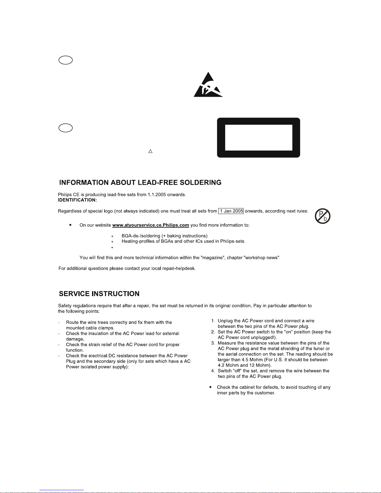
Frame aerial
e.g. 7122 707 89001
Tuner AM (MW,LW)
To avoid atmospheric interference all AM-measurements have to be carried out in a Faraday´s cage.
Use a bandpass filter (or at least a high pass filter with 250Hz) to eliminate hum (50Hz, 100Hz).
RF Generator
e.g. PM5326
Ri=50:
Bandpass
250Hz-15kHz
e.g. 7122 707 48001
LF Voltmeter
e.g. PM2534
DUT
RF Generator
e.g. PM5326
S/N and distortion meter
e.g. Sound Technology ST1700B
Use a bandpass filter to eliminate hum (50Hz, 100Hz) and disturbance from the pilottone (19kHz, 38kHz).
Ri=50:
Tuner FM
MEASUREMENT SETUP
1-4
SERVICE AIDS
GB
WARNING
All ICs and many other semi-conductors are
susceptible to electrostatic discharges (ESD).
Careless handling during repair can reduce life
drastically.
When repairing, make sure that you are
connected with the same potential as the mass
of the set via a wrist wrap with resistance.
Keep components and tools also at this
potential.
ESD
CLASS 1
LASER PRODUCT
GB
Safety regulations require that the set be restored to its original
condition and that parts which are identical with those specified,
be used
Safety components are marked by the symbol
!
.
Lead free
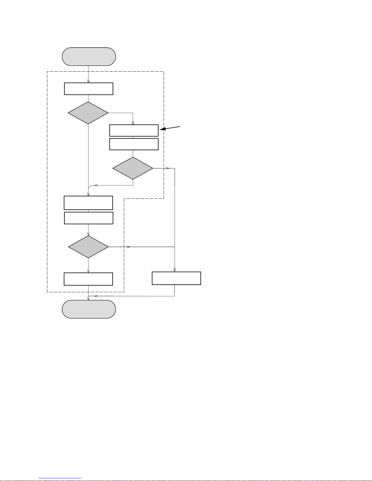
Set remains closed!
N
Y
Play a CD
for at least 10 minutes
Y
playability
ok ?
N
playability
ok ?
add Info for customer
"SET OK"
check playability
N
Y
playability
ok ?
check playability
check playability
return set
Customer complaint
"CD related problem"
"fast" lens cleaning
1
2
3
For flap loaders (= access to CD drive possible)
cleaning method
4 is recommended
INSTRUCTIONS ON CD PLAYABILITY
2 - 1
Exchange CDM
1 - 4 For description - see following pages
1
PLAYABILITY CHECK
For sets which are compatible with CD-RW discs
use CD-RW Printed Audio Disc....................7104 099 96611
TR 3 (Fingerprint)
TR 8 (600µ Black dot) maximum at 01:00
• playback of these two tracks without audible disturbance
playing time for: Fingerprint
10seconds
Black dot from 00:50 to 01:10
• jump forward/backward (search) within a reasonable time
For all other sets
use CD-DA SBC 444A..................................4822 397 30245
TR 14 (600µ Black dot) maximum at 01:15
TR 19 (Fingerprint)
TR 10 (1000µ wedge)
• playback of all these tracks without audible disturbance
playing time for: 1000µ wedge 10seconds
Fingerprint 10seconds
Black dot from 01:05 to 01:25
• jump forward/backward (search) within a reasonable time
2
CUSTOMER INFORMATION
It is proposed to add an addendum sheet to the set which
informs the customer that the set has been checked
carefully - but no fault was found.
The problem was obviously caused by a scratched, dirty or
copy-protected CD. In case problems remain, the customer
is requested to contact the workshop directly.
The lens cleaning (method 3) should be mentioned in the
addendum sheet.
The final wording in national language as well as the printing
is under responsibility of the Regional Service Organizations.
4
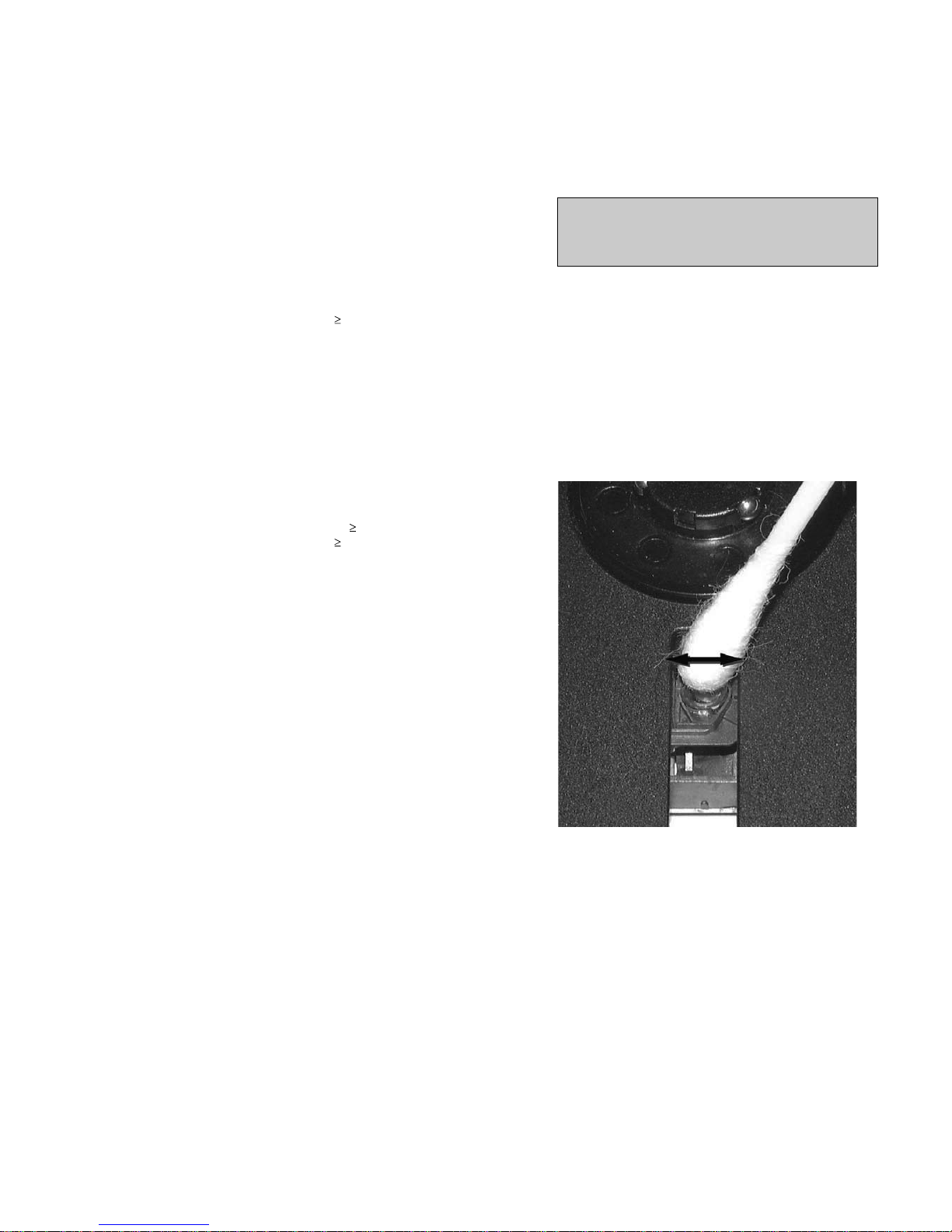
LIQUID LENS CLEANING
Because the material of the lens is synthetic and coated
with a special anti-reflectivity layer, cleaning must be done
with a non-aggressive cleaning fluid. It is advised to use
“Cleaning Solvent
The actuator is a very precise mechanical component and
may not be damaged in order to guarantee its full function.
Clean the lens gently (don’t press too hard) with a soft and
clean cotton bud moistened with the special lens cleaner.
The direction of cleaning must be in the way as indicated in
the picture below.
Before touching the lens it is advised to clean the
surface of the lens by blowing clean air over it.
This to avoid that little particles make scratches on
the lens.
INSTRUCTIONS ON CD PLAYABILITY
2 - 2

How to set region code:
1) Press "SYSTEM MENU" on Remote Control ---->
select "DEFAULT" and then select "RESTORE" .
It can reset the region code.
2) To change the region code ----> open CD door at CD mode and press "5168" on RC
----> select
"REGION" and select region code.
1) MCU version : at standby mode, press and hold "DBB" & "PLAY" buttons at the same time.
Servo version : CD mode, open CD door and press "5168" on Remote Control.
Software checking:
SOFTWARE VERSION CHECKING AND REGION CODE RESET
4 - 1 4 - 1

SET BLOCK DIAGRAM
5 - 1
5 - 1

6 - 1
6 - 1
SET WIRING DIAGRAM
7 - 17 - 1
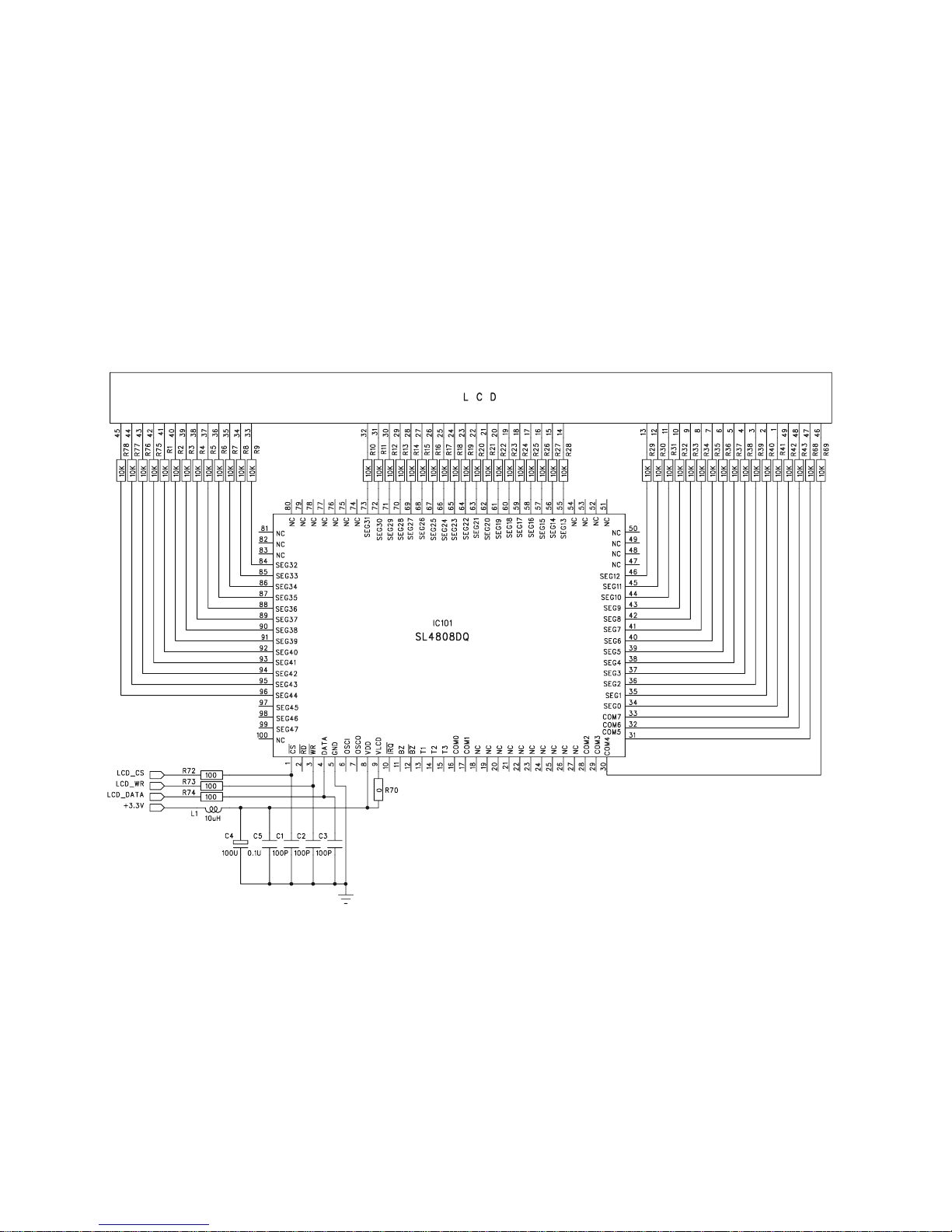
CIRCUIT DIAGRAM - LCD & KEY BOARD
Part 1
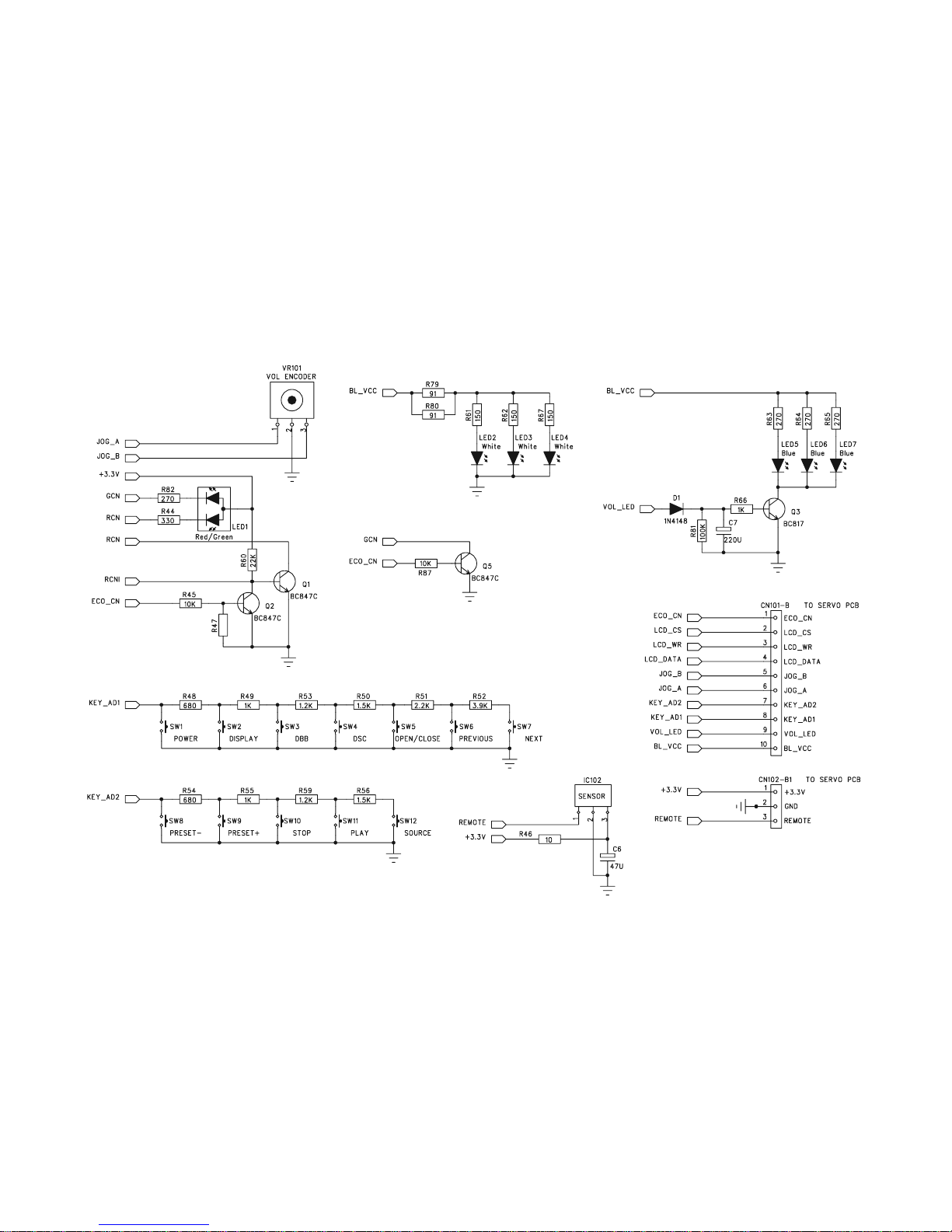
7 - 2 7 - 2
CIRCUIT DIAGRAM - LCD & KEY BOARD
Part 2
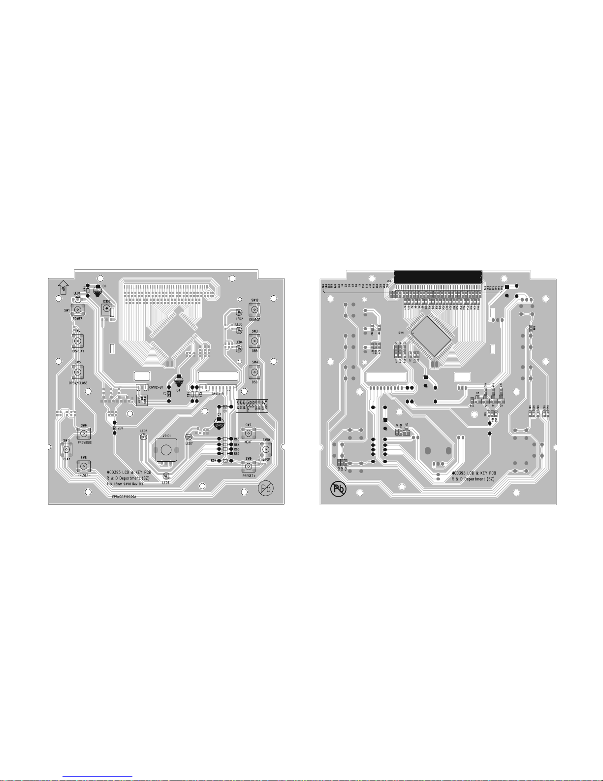
LAYOUT DIAGRAM - LCD & KEY BOARD
7 - 3
7 - 3
 Loading...