

Page 1

Cardiograph
Signal-Averaged ECG
M1754A
INSTRUCTIONS FOR USE
Page 2

Page 3

M1754A Signal-Averaged
ECG (SAECG) Instructions for Use
Philips Cardiograph
3KLOLSV3DUW1R0
3ULQWHGLQ86$-DQXDU\
(GLWLRQ
Page 4

Notice
About This Edition
Publication number M1754-91908
Edition 3
Printed in USA
Edition History
October 1991 Edition 1
June 1992 Edition 2
January 2002 Edition 3
Copyright
Copyright © 2001
Philips Electronics North America Corporation
All rights are reserved.
Reproduction in whole or in part is prohibited
without the prior written consent of the
copyright holder.
Philips Medical Systems
Andover, MA 01810 USA
This informatio n is s ub ject to change without
notice.
Warranty
Philips makes no warranty of any kind with
regard to this material, included, but not limited
to, the implied warranties or merchantability
and fitness for a particular purpose .
Philips shall not be liable for errors co nta ined
herein or for incidental or conseque ntial
damages in connection with the furni s hi ng,
performance, or use of this material.
This product may contain rem anufactured parts
equivalent to new in performance or have had
incidental use.
Philips assumes no li abilit y for f ailures resultin g
from RF interference between Philips medical
electronics and any radio frequency generating
equipment at levels exceeding those established
by applicable standards.
Classified by Underwriters Laborato ries , Inc.
with respect to electrical shock, fire, and
mechanical hazards only in accordance with UL
2601-1.
CAUTION
The manufacture r, importe r and seller are
responsible for the effects on safety, reliability
and performance only if: assembly operations,
extensions, re-adjustments, modi fications or
repair are carried out by persons authorized by
them, and the electrical installation of the
relevant room complies with all local
regulations and the equipment is used in
accordance with the instructions for use . Us e of
accessories other than those recommended by
Philips may compromise product performance.
THIS PRODUCT IS NOT INTENDED FOR
HOME USE.
Responsibility of Manufacturer
Philips only considers it s elf responsib le for any
effects on safety, reliability and performance of
the PageWriter cardiograph and the battery
support system if:
assembly operations, extensions, readjustments,
modifications or repairs are don e by persons
authorized by He wl ett Packard, and
the electrical installation of the relevant room or
vehicle complies with the IEC or national
requiremen ts , and
the instrument is used according to the
instructions for use presented in this manual.
WARNING
As with electroni c e quipment, Radio
Frequency (RF) interference between the
defibrillator and any existing RF transmitting or
receiving equipment at the installat io n site,
including electrosurgica l equipment, should
evaluated carefully and a ny limitations noted
before the equipm ent is placed in servic e.
Monitoring during quiescent periods of
electrosurgery is possible but electromagnetic
interference generated by electrosurgical tools
during operation is sufficient to mask cardiac
signals.
Radio frequency generat io n from
electrosurgical equi pment and close prox imity
transmitters may seriously degrade performance
of the PageWriter cardiograph.
ii
Page 5

1
1Printing History
October 1991 Edition 1
June 1992 Edition 2
January 2002 Edition 3
iii
Page 6
1
127(
1Safety Summary
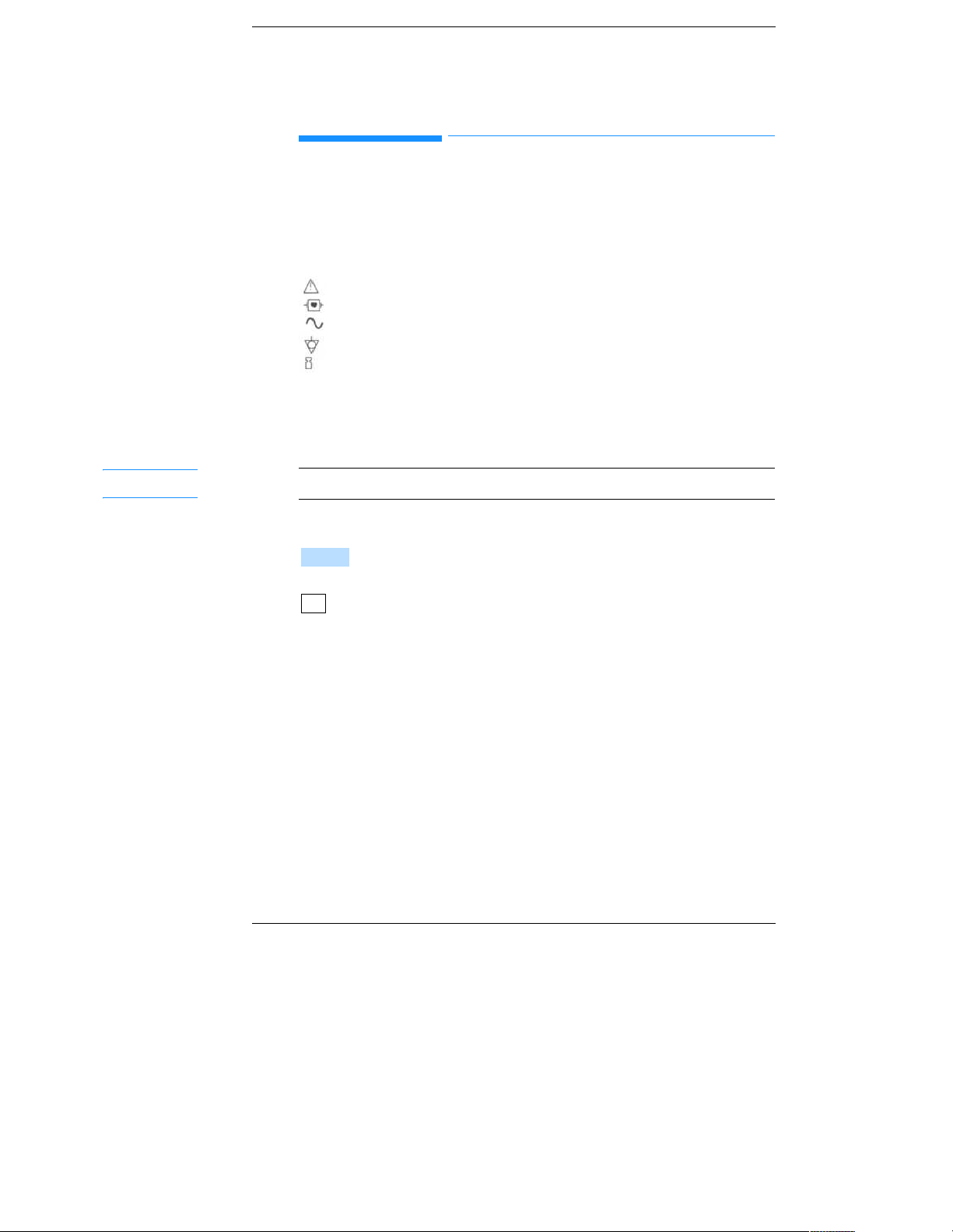
Safety Symbols Marked on the Cardiograph
The following symbols are used on the cardiograph or the cart.
Caution - See operating instructions
Type CF, defibrillation protected
Alternating current
Equipotential (this is on the ground lug)
The maximum weight that the cart can hold.
Conventions Used in This Manual
Notes contain additional information on M1754A usage.
VRIWNH\V
represents the temporary key labels that appear on the display.
represents keys on the front panel.
.H\
iv
Page 7

Contents
1. Getting Started
Introduction . . . . . . . . . . . . . . . . . . . . . . . . . . . . 1-1
Installing M1754A SAECG Software . . . . . . . . 1-1
Selecting the SAECG Application . . . . . . . . . . . 1-3
Preparing the Patient and Applying Electrodes . 1-4
2. Acquiring a Signal-Averaged ECG
Selecting the Template Beat . . . . . . . . . . . . . . . . 2-1
Editing the Final Report . . . . . . . . . . . . . . . . . ... .2-5
Adjusting the QRS Onset and Offset . . . . . . . . . 2-5
Editing and Printing a Stored SAECG . . . . . . . . 2-7
3. Understanding the Printed SAECG Report
4. Configuring the M1754A SAECG Application
Configuring Your Cardiograph to Start Up
in the SAECG Application . . . . . . . . . . . . . . 4-1
Configuring the SAECG Application . .. . . . . . . 4-3
Patient ID Fields . . . . . . . . . . . . . . . . . . . . . . . . 4-4
Configuration Tables . . . . . . . . . . . . . . . . . . . . . 4-5
Acquisition Fields . . . . . . . .. . . . . . . . . . . . . . . . 4-5
Measurement Fields . . . . . . . . . . . . . . . . . . . . . . 4-6
5. Troubleshooting
Error Messages . . . . . . . . . . . . . . . . . . . . . . . . . 5-2
Glossary
Index
contents 1
Page 8

Figures
1-1. Placing Electrodes for an SAECG. . . . . . . . 1-5
2-1. A Template Screen. . . . . . . . . . . . . . . . . . . .2-2
2-2. An Averaging Screen . . . . . . . . . . . . . . . . . 2-4
2-3. A Measurements Screen . . . . . . . . . . . . . . . 2-5
3-1. The SAECG Report. . . . . . . . . . . . . . . . . . . 3-2
Tables
1-1. SAECG Electrode Positions . . . . . . . . . . . . 1-5
3-1. SAECG Report Annotations . . . . . . . . . . . . 3-3
4-1. Acquisition Configuration Fields . . . . . . . . 4-5
4-2. Measurements/Processing Configuration
Fields . . . . . . . . . . . . . . . . . . . . . . . . . . . . . . . 4-6
5-1. SAECG Testing Problems . . . . . . . . . . . . . 5-2
contents 2
Page 9

1Getting Started
1Introduction
This guide contains information about using the M1754A Signal-Averaged ECG
(SAECG) cardiograph application to acquire a Signal-Averaged ECG for use in the
detection of late potentials. There are also instructions on configuring the
cardiograph for M1754A SAECG application operation.
Refer to the Page Writer XLi Cardiograph Operating Guide for operating and
installation instructions for your cardiograph.
1Installing M1754A SAECG Software
Be sure that the M1700A XLi software has been installed before installing any other
applications in your cardi ogr aph. To ins t all th e M175 4A S AECG so ft ware, perform
the following steps.
1. Turn the cardiograph to Standby from the front panel.
2. Insert the M1754A SAECG application disk in the disk drive in the front of the
cardiograph.
3. Prepare the SAECG patient module and attach it to the cardiograph.
a. Put shorting plugs in the LA and LL positions.
b. Attach lead wires to the remaining positions on the SAECG patient module.
1-1
Page 10
*HWWLQJ6WDUWHG
127(
,QVWDOOLQJ0$6$(&*6RIWZDUH
The SAECG patient module can also be used for XLi applications. If you wish to
routinely acquire XLi ECGs as well as SAECGs, you may attach lead wires in place
of the shorting plugs for the LA and LL leads on the SAECG patient module. Then
attach the LA and LL electrodes on the normal positions.
You will achieve shorter averaging times if you use shorting plugs in the LA and LL
lead positions.
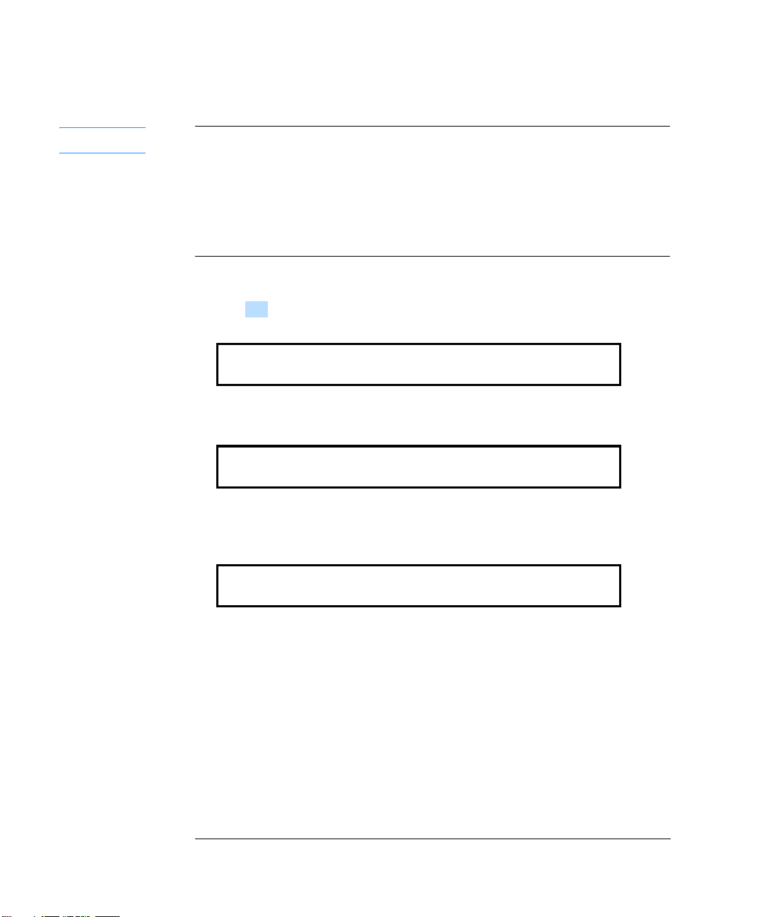
4. Turn the cardiograph on. The message Load SAECG application? appears.
5. Press . The copyright display appears briefly.
<H V
(c) 1991 Hewlett-Packard, Corazonix Corp
SAECG (M1754A - A.01.00)
Then the following display appears.
******
SAECG (M1754A - A.01.00)
The asterisks gradually extend across the display until the software install a tion
is complete. The following display appears.
Auto 3x4
Report Format 01/26/92 01:23AM
You can now select the SAECG application as described in the next section.
T o conf i gure your cardiograph for your requirements, refer to Chapter 4.
1-2
Page 11

*HWWLQJ6WDUWHG
Reformat Timed Cont Prev Delayed Exit
6HOHFWLQJWKH6$(&*$SSOLFDWLRQ
1Selecting the SAECG Application
When the SAECG application is installed, you can either use your cardiograph to
acquire a standard (XLi) ECG or you can acquire Signal-Averaged ECGs. To select
SAECG opera t i on from the Prev iew Plus application, perform the following steps.
1. Press until you see the following display.
0HQX
Prev+
2. Press .
3. In the Applications menu, press .
([LW
6$(&*
• If you haven't already attached the SAECG patient module, you will be instructed
to do so.
The following display appears.
SAECG
Start 01/26/92 01:23AM
4. Attach the electrodes to the patient as described in the next section.
5. Check the signal quality by viewing the preview screen and the SAECG patient
module display.
The next chapter, Chapter 2, describes how to acquire the ECG and create the final
SAECG report.
1-3
Page 12

*HWWLQJ6WDUWHG
127(
127(
3UHSDULQJWKH3DWLHQWDQG$SSO\LQJ(OHFWURGHV
1Preparing the Patient and Applying Electrodes
To prepare the patient and apply the electrodes, perform
the following steps.
1. Relax the patient.
• Check that the patient is comfortable.
• Reassure the patient that the procedure is safe.
It is essential to relax the patient as much as possible during the procedure. This is
because the quality of the ECG signal depends on reducing tension in the patient.
2. Prepare the electrode positions.
• Shave the electrode positions if necessary.
• Cleanse the skin with your institution's cleansing soluti on .
• Rub the skin gently with a gauze pad until the skin is slightly red.
Electrode site preparation is especially important for the detection of the low level
signals involved in late potentials.
1-4
Page 13

3. Place the electrodes as shown in Figure 1-1.
*HWWLQJ6WDUWHG
3UHSDULQJWKH3DWLHQWDQG$SSO\LQJ(OHFWURGHV
AHA IEC Position
Y+
YZ+
ZX+
X-
RL
LA
LL
Y+
In the lower, left abdominal region on the left iliac
crest
Y-
On the superior aspect of the manubrium.
Z+
At the fourth in tercostal space, at the le ft s ternal
margin (V 2 po s ition)
Z-
On the back, directly opposite the Z+ electrode
X+
At the same level as the Z axis along the mid-axillary
line on the pati en t’s left si d e
X-
At the same level as the Z axis along the mid-axillary
line but on the patient’s right side
N
Opposite the Y+ electrode on the right iliac crest
L
On the left fo re arm (if used)
F
On the left leg (i f u se d )
1-5
Page 14

*HWWLQJ6WDUWHG
3UHSDULQJWKH3DWLHQWDQG$SSO\LQJ(OHFWURGHV
1-6
Page 15

2Acquiring a Signal - Averaged ECG
0HQX
6WDUW
This chapter contains information on how to acquire a Signal-Averaged
ECG. There are three steps to acquiring a Signal-Averaged ECG.
1. Selecting a template beat.
2. Acquiring and averaging ECG data.
3. Verifying the onset and offset of the QRS complex.
2Selecting the Template Beat
You must confirm the template beat to start the signal averaging process.
Perform the following steps to select a template beat.
1. Press until the following menu is displayed.
SAECG
Start 01/26/92 01:23AM
2. Press . The message Determining template beat... appears. Then
the following display appears.
Select the template.
Select Reject Match Noise Exit
2-1
Page 16

$FTXLULQJD6LJQDO$YHUDJHG(&*
6HOHFWLQJWKH7HPSODWH%HDW
The template beat with the matching and noise windows appears on the
preview screen as shown in Figure 2-1.
2-2
3. To confirm the template beat, press .
6HOHFW
• If you wish to place the template on another lead, use the and keys.
• If you wish to acquire a new template beat, press .
• If you wish to adjust the matching window, press .
5HMHFW
0DWFK
You can obtain best results when the matching window contains the fast
rising portion of the R wave.
If you wish to adjust the noise window, press .
1RLVH
Be sure that the noise window is on a flat part of the signal and that the T
wave is not inside the window.
Page 17

$FTXLULQJD6LJQDO$YHUDJHG(&*
'RQH
6HOHFWLQJWKH7HPSODWH%HDW
When you press or , perform the following steps to adjust the
0DWFK 1RLVH
windows.
a. Use and keys to adjust the position of the windows.
b. Press . The following display returns.
Select the template.
Select Reject Match Noise Exit
After you have selected the template beat, the message Averaging... appears
and the preview screen displays a continuous ECG sig nal for leads X, Y, and
Z as shown in Figure 2-2. The message remains on the screen until the end
condition is met.
The end condition is configured on your cardiograph. The default end
condition is a noise level of less than 0.3
µV, but the end condi tion could be
configured to a specified number of beats or a selected noise level. The
number of beats and the noise level are displayed on the preview screen
during averaging.
2-3
Page 18

$FTXLULQJD6LJQDO$YHUDJHG(&*
127(
'RQH
6HOHFWLQJWKH7HPSODWH%HDW
Y o u can press at any time to end the averaging process be fore it meets
the configured end condition.
2-4
Once the averaging process is complete, the message Filtering averaged
beats... appears.
Page 19

$FTXLULQJD6LJQDO$YHUDJHG(&*
(GLWLQJWKH)LQDO5HSRUW
2Editing the Final Report
After the ECG signals are averaged and filtered, the final SAECG
information is displayed on the preview screen. You can adjust the QRS
onset and offset before printing and storing the SAECG report.
2Adjusting the QRS Onset and Offset
The QRS complex on the final report has its onset and offset marked for
signal averaging measurements. It is essential that the onset and offset in any
individual lead or in the vector are properly placed to produce accurate
measurements. If you must adjust the QRS onset and offset on the final
report, perform the following steps.
1. When averaging is finished, the following message appears on the display.
Adjust the onset and offset.
Print Onset Offset Lead Exit
At the same time the Measurements screen, as shown in Figure 2-3, appears
on the preview screen.
2-5
Page 20

$FTXLULQJD6LJQDO$YHUDJHG(&*
$GMXVWLQJWKH4562QVHWDQG2IIVHW
2. Ensure that a flexible disk for storage is in the cardiograph’s disk drive.
3. If the QRS complex’s onset and offset are correctly placed by default and
you want a printed report, press . The message Printing report ...
3ULQW
appears before the report is stored.
• If you wish to change the waveform's scale, use the and keys.
• If you wish to move the onset, press .
• If you wish to move the offset, press .
2QVHW
2IIVHW
The following display appears.
Adjust the onset
Done Exit
a. Use the and keys to move the onset or offset windows left or right.
b. Press when the QRS onset and offset are correctly placed.
• If you wish to view another lead, press . The following display
'RQH
/HDG
appears.
Choose another lead
Vector X Y Z Exit
2-6
m If you wish to view the X, Y, or Z lead, press , , or respec-
; < =
tively. You can then change the onset and offset on the leads if desired.
m If you wish to display the combined vector lead on the preview screen for
editing or viewing, press .
9HF WR U
After selecting a lead you can adjust the onset and offset independently for
all leads plus the combined vector lead.
Page 21

$FTXLULQJD6LJQDO$YHUDJHG(&*
127(
'RQH
0HQX
([LW
(GLWLQJDQG3ULQWLQJD6WRUHG6$(&*
After printing, the report will be st o red. If your appl icatio n is configured for
manual file naming, you will be prompted to provide a file name.
a. To store a report with a specified file name, type a name with up to eight
characters and with a three-digit extension; for exampl e, W enw orth.001. You
can also use the patient ID for a file name if the ID is under eight characters.
Manually enter the file name if you intend to use this file on a Corazonix
Predictor for additional study.
b. Press . The message Storing report... appears, then the display
returns to the SAECG display.
2Editing and Printing a Stored SAECG
You can edit and print a stored SAECG report. To retrieve a stored SAECG
report so you can edit and print the report, perform the following steps from
the SAECG application.
1. Insert the storage disk that has the SAECG report you wish to edit or print
into the cardiograph disk drive.
2. Press until the following display appears.
Print Edit Config
3. Press . The following display appears.
12345678 12/01/91 01:07 PM
Select Next Previous Exit
2-7
Page 22

$FTXLULQJD6LJQDO$YHUDJHG(&*
3UHYLRXV
(GLWLQJDQG3ULQWLQJD6WRUHG6$(&*
4. Press or until the correct patient ID number appears.
1H[W
3UHYLRXV
5. Press . The following display appears.
Adjust the onset and offset.
Print Onset Offset Lead Exit
You can now adjust the onset and offset and print the SAECG report as
described earlier in Editing the Final Report. If you wish, you can also print
the SAECG report without editing it.
You can delete stored SAECGs from the Preview + or XLi menus the same
way ECGs are deleted.
2-8
Page 23

3Understanding the Printed SAECG Report
This chapter contains information about the printed SAECG report. The
report is printed on the PageWriter XLi printer. The SAECG report gives a
concise summary of the SAECG test.
3-1
Page 24

8QGHUVWDQGLQJWKH3ULQWHG6$(&*5HSRUW
3-2
Page 25

8QGHUVWDQGLQJWKH3ULQWHG6$(&*5HSRUW
Table 3-1. SAECG Report Annotations
Description
A
B
C
D
E
F
G
H
I
J
K
Patient ID number
Date and Time
Patient Name
Department,
Room number,
Operator
Age and Sex
Comments
Configured Settings
Measurements
Unfiltered Lead Waveforms
Absolute Filtered Lead Waveforms
Vector Size
3-3
Page 26

8QGHUVWDQGLQJWKH3ULQWHG6$(&*5HSRUW
3-4
Page 27

4Configuring the M1754A SAECG Application
This chapter describes how to conf i gur e you r cardi o grap h fo r use w ith the M17 54A
SAECG application. Tables at the end of this chapter show which operating
parameters are configurable.
4Configuring Your Cardiograph to Start Up in the SAECG
Application
If you wish to configure your cardiograph to start up in the SAECG application,
perform the following steps from the main XLi application.
1. Press until the following display appears
0HQX
Transmit Store Config CheckDisk Files
4-1
Page 28

&RQILJXULQJWKH0$6$(&*$SSOLFDWLRQ
127(
&RQILJXULQJ<RXU&DUGLRJUDSKWR6WDUW8SLQWKH6$(&*$SSOLFDWLRQ
2. Press . The main configuration menu will appear:
&RQILJ
Configuration
Global ID Transmit Files Exit
If this is not the initial configuration, you might need to type the configured
password before you can make any changes to the configuration.
3. Press and the following display appears.
*OREDO
Initial Interpretation? Reasons
Enter Choose Previous Exit
4. Press to step through the global configuration fields until the following
(QWHU
field appears.
Power on application? XLi
Enter Choose Previous Exit
5. Press until SAECG appears on the display.
6. Press and the SAECG setting will be accepted. The next configuration
&KRRVH
(QWHU
parameter will appear.
7. Press when you have finished changing the main configuration settings.
([LW
Your cardiograph will now start up in the SAECG application when you turn it on.
4-2
Page 29

&RQILJXULQJWKH0$6$(&*$SSOLFDWLRQ
&RQILJXULQJWKH6$(&*$SSOLFDWLRQ
4Configuring the SAECG Application
The M1754A SAECG application has default operating parameters when it is
installed on your cardiograph. To customize the SAECG operating parameters,
perform the following steps from the SAECG application.
1. From the main SAECG menu, press until the following menu is displayed.
0HQX
Print Edit Config
2. Press . The SAECG Configuration menu is displayed.
&RQILJ
SAECG Configuration
ID Acquis Meas Exit
3. Press one of the softkeys on the SAECG configuration menu to configure the
SAECG application for your institution.
• If you wish to determine which ID parameters are requested each time you enter
patient informatio n , press .
• If you wish to choose Acquisitio n par a met e rs, press .
• If you wish to choose Measurements parameters, press .
,'V
$FTXLV
0HDV
The following sections describe how to configure ID, Acquisition, and
Measurements operating parameters.
4-3
Page 30

&RQILJXULQJWKH0$6$(&*$SSOLFDWLRQ
3DWLHQW,')LHOGV
4Patient ID Fields
You don’t have to step through all the possible patient ID information each time you
enter patient ID. You can turn off the ID fields that you don’t use. The only
information you must include for storage is the patient ID number.
The following list shows each patient ID configuration option. You can choose
either Yes to include or No to exclude that item from the patient ID information
printed on the ECG. Yes is the default choice for all.
• Allow NAME entry?
• Allow AGE entry?
• Allow SEX entry?
• Allow OPERATOR entry?
• Allow DEPARTMENT entry?
• Allow ROOM entry?
• Allow COMMENTS entry?
4-4
Page 31

&RQILJXULQJWKH0$6$(&*$SSOLFDWLRQ
A
T
T
Configuration Tables
Table 4-1 and Table 4-2 show configurable operations on the M1754A SAECG
application. The setting choices that are shown in bold type are the default settings.
These settings are adequate for most applications.
cquisition Fields
able 4-1 shows Acquisition configuration choices.
able 4-1. Acquisition Configuration Fields
Parameter Set ting Choices Comments
Fiducial point?
Correlation coefficient? (0.01- 0.99)
Average to?
Noise level? (0 - 100
Number of beats? (1 - 9999)*
µV)*
Left
Center
Right
0.99
Type a number
between
0.01 and 0.99
Noise level
Beats
0.3 µV
Type a number
between
0.0 and 100.0
200
Type a number
between
1 and 9999
The peak of the QRS can be
moved from the center to either
the right or left third of the
display and printed report. The
noise window is moved by the
same amount as the fiducial
point.
This sets how closely the acquired
beats must match the template.
A value of 0.99 is as close as
possible.
The end of the averaging process
is controlled by either a total
number of accepted beats, or an
average noise level of the three
leads.
The noise level required before
the process completes. * This
field appears only if Noise level is
selected in the Average to? field.
The total beats that must be
collected before the process
completes. * This field appears
only if Beats is selected in
Average to? field.
3DWLHQW,')LHOGV
4-5
Page 32

&RQILJXULQJWKH0$6$(&*$SSOLFDWLRQ
3DWLHQW,')LHOGV
4-6
Page 33

4Troubleshooting
127(
This chapter contains information about troubleshooting the M1754A
operation. Cardiograph troubleshooting is covered in more detail in the
PageWriter XLi Cardiograph Operating Guide and the PageWriter XLi
Cardiograph Instructions for Use.
Be sure that you have the SAECG patient module attached to the
cardiograph for use with the M1754A application.
ECG technique is particularly important for ensuring a good recording. An
extremely noisy ECG signal can take too long to average. Three problems
that could prevent you from acquiring an SAECG include:
• Muscle artifact
• Bad lead contact
• Electrical interference
Chapter 1 includes more information on ECG technique.
5-1
Page 34

7URXEOHVKRRWLQJ
(UURU0HVVDJHV
4Error Messages
Error messages appearing on the display instruct you as to what action to
take. If the error is something th at you can correct, the message in structs you
what to do.
5-2
Page 35

4Glossary
applications
Software used for a specific task. The PageWriter XLi has the SAECG
application and the Preview Plus application.
combined vector lead
A combination of three orthogonal leads. It is derived from the sum of the
squares of the three leads, and then the square root of that sum.
configuration
The preset operating parameters for the cardiograph. When the software is
installed, the cardiograph defaults to a preset configuration which may be
customized any time.
correlation coefficient
A number that shows how closely that the acquired beats must match the
template beat. O indicates the least close match; 1 indicates the closest
match.
end condition
The point when the designated number of beats are acquired or the level of
noise is reached in order to have enough clear ECG data to average.
Glossary-1
Page 36

*ORVVDU\
fiducial point
A reference point based on the peak of the QRS complex. This adjustment
enables you to average on different parts of the waveform.
filtered lead scaling
The size at which the filtered leads are displayed.
filter frequency
Frequency on the high pass filter above which an ECG signal is recorded.
For example, a filter frequency of 80 1Iz means that frequency components
below 80 Hz are removed.
flexible disk
A disk which can be inserted in the disk drive to store data such as ECG and
SAECG reports or the configuration. Software is installed from a flexible
disk.
function keys
The line of keys lettered F1 to F5 at the top of the keyboard that correspond
to the labels displayed at the bottom of the screen.
matching window
The area of the template beat that will be correlated to each new beat.
0HQX
Cardiograph key that changes the menu selections displayed on the
cardiograph’s front panel display.
Glossary-2
key
Page 37

*ORVVDU\
noise window
The area of the template beat used to determine the amount of noise in the
signal. This should be the smoothest part of the beat.
operating parameters
Configured settings that permit the SAECG application to function in a
desired manner.
password
Private code word that limits access to the cardiograph’s configuration
software to those persons knowing the code word. Passwords prevent
accidental or unauthorized changes to cardiograph configuration.
Preview Plus
Philips name for optional software application which enhances th e standard
preview screen.
preview screen
Philips term for the screen which, when installed on the cardiograph, shows
the ECG traces as they will appear on the printed ECG report. The preview
screen is required for the SAECG application.
QRS onset and offset
The beginning and end of the QRS complex.
SAECG patient module
The remote patient unit that contains all of the cardiograph’s SAECG
data acquisition electronics. The patient module connects to the patient data
cable and to the leads attached to the patient.
Glossary-3
Page 38

*ORVVDU\
signal averaging
Averaging performed on an ECG waveform to reduce random noise.
Signal-Averaged ECG (SAECG)
A report produced by the M1754A to aid in the detection of late potentials.
softkeys
The function keys labelled in the lower portion of the cardiograph’s front
panel display and physically positioned underneath the display. These keys
change functions when they are pressed. The matching display label also
changes.
template beat
A typical beat used to match other beats dur ing aver aging . When selecting a
template beat, choose a clean beat without a lot of noise.
vector scaling
The size at which the combined leads are displayed.
Glossary-4
Page 39

Index
6
6503, 5-2
A
acquiring a Signal-Averaged ECG, 2-1
Acquis, 4-3
acquisition configuration, 4-5
adjusting the onset and offset , 2-6
Adjust the onset., 2-6
Adjust the onset and offset., 2-5
AGE entry, 4-4
application, 1-1, Glossary-1
application disk, 1-2
Applications menu, 1-3
artifact, muscle, 5-1
Attach SAECG patient module., 5-2
automatic file naming , 2-7 , 4- 6
automatic scaling
filtered leads, 4-6
unfiltered leads, 4-6
averaging, 2-3, 2-5
shorter times, 1-2
Averaging..., 2-3
Averaging screen, 2-3
B
beat
template, 2-1, Glossary-4
beats, number of, 4-5, Glossary-1
C
changing. See adjusting, editing
matching window, 2-2
noise window, 2-2
the onset and offset, 2-5, 2-6
the scale, 2-6
Choose another lead., 2-6
combined vector lead, 2-6, Glossary-1
COMMENTS entry, 4-4
Config, 4-2
configuration, Glossary-1
acquisition, 4-5
measurements, 4- 6
patient ID, 4- 4
start up, 4-2
Configuration menu, 4-2
configured settings, 3-3
configuring your cardio gra ph, 1-2, 4-1-6
copyright display, 1-2
Corazonix Predictor
correlation coefficient, 4-5, Glossary-1
correlation window. See matching window
customizing operating parameters, 4-1
®, 2-7
D
DEPARTMENT entry, 4-4
Determining template be at. . .,2-1
disk
application, 1-1, 1-2
storage, 2-6, 2-7
disk drive, cardiograph, 1-1, 2-6, 2-7
Done, 2-3, 2-4, 2-6, 2-7
E
ECG
noisy, 5-1
technique, 5-1
Edit, 2-7
editing. See ad justing, changin g
a lead, 2-6
combined vector lead, 2-6
final report, 2-5
stored SAECG, 2-7
electrical interference, 5-1
electrodes, 1-3
placing, 1-5
positions, 1-5
site preparation, 1-4
end condition, 2-3, Glossary-1
error messages, 5-2
Exit, 2-3, 2-8, 4-3
F
fiducial po int, Glossary - 2
fiducial point configuration, 4-5
file name, 2-7
file naming
automatic, 4-6
manual, 4- 6
filtered lead
scale, 4-6
scaling, 4-6, Glossary-2
waveforms, 3-3
filter frequency, 4-6, Glossary-2
Filtering averaged beats..., 2-4
final report
editing, 2-5
flexible disk, 2-6, Glossary-2
function keys, Glossary-2
H
high pass filter frequency, 4-6
Hi-Res ECG. See SAECG
I
identification, patient. See patient ID
ID fields
configuring, 4-4
turning off, 4-4
iliac crest, 1- 5
Index-1
Page 40

installing M1754A SAECG software, 1-1
interferenc e, electrical, 5-1
L
LA
electrode, 1-5
position, 1-1
late potentials, 1-1, 1-4, Glossary-4
lead
contact, 5-1
orthogonal, Glossary-1
viewing another, 2-6
Lead, 2-6, 2-8
lead off , 5-2
LL
electrode, 1-5
position, 1- 1
Load SAECG application?, 1-2
M
M1754A SAECG
application, 1-1
configuring, 4-1-6
installing software, 1-1
manual file naming, 2-7, 4-6
manubrium, 1-5
Match, 2-2, 2-3
matching window, 2-2, Glossary-2
adjusting, 2-2
Meas, 4-3
measurements, 3- 3
configuration, 4-6
Measurements screen, 2-5
Menu
, 1-3, 2-1, 2-7, Glossary-2
mid-axillary line, 1-5
mid-clavicular l ine , 1 -5
muscle artifact, 5-1
N
NAME entry, 4-4
naming a file
automatically, 2-7, 4-6
manually, 2-7, 4-6
No heartbeat. Check connections., 5-2
Noise, 2-2, 2-3
noise level, 2-3, 5-2
configuring, 4-5
noise window, 2-2, Glossary-2
adjusting, 2-2
noisy signal, 5-2
No room to load application., 5-2
number of beats, 2-3
O
Offset, 2-8
Onset, 2-8
onset and offset
adjusting, 2-6
operating parameters, Glossary-3
customizing, 4-1, 4-3
OPERATOR entry, 4-4
orthogonal leads, Glossary-1
P
password, 4-2, Glossary-3
patient
preparing, 1-4
relaxing, 1-4
patient ID
configuration, 4-4
number, 3-3
patient module, SAECG, 1-1 , 5-1
placing electrodes, 1- 5
power on application, 4-2
preparing the patien t, 1-4
Preview Plus, Glossary-3
preview screen, 1-3, 2-3, 2-5, Glossar y-3
Print, 2-7, 2-8
Printing report... , 2-6
printing the report, 2-6, 2-8
Q
QRS
adjusting the onset and offset , 2-5
complex, 2-1
onset and offset, 2-1, 2-6, Glossary-3
peak, 4-5
R
reducing tension, 1-4
Reject, 2-2
relaxing the patient, 1-4
RL electrode, 1-5
ROOM entry, 4-4
R wave, 2-2
S
SAECG, 1-3, 1-5
acquiring, 2-1
application disk, 1-2
display, 2-7
editing a stored, 2-7
patient module, 1-1, 5-1, Glossa ry-3
printing a stored, 2-7
SAECG Configuration me nu, 4-3
SAECG report, 3-1-3
editing, 2-5
SAECG test, 5-2
scale
changing, 2-6
Index-2
Page 41

Select, 2-2, 2-8
Select the template.,2-1
SEX entry, 4-4
shorting plugs, 1-1, 1-2, 1-5
Signal-Averaged ECG, 1-1, 1-3, Glossary-4
signal averaging, G lossary-3
signal quality, 1-3, 1-4
softkeys, iii, 4-3, Glossary-4
Standby key, 1-1
Storing report..., 2-7
storing the report, 2-6, 2-7
T
template beat, 2-1, Glossary- 4
confirming, 2-2
Template screen, 2-2
troubleshooting, 5-1-2
T wave, 2-2
U
unfiltered lead
scale, 4-6
scaling, 4-6
waveforms, 3-3
V
vector
scale, 4-6
scaling, 4-6, Glossary-4
size, 3-3
Vector , 2- 6
viewing
another lead, 2-6
combined vector lead, 2-6
X
X+ electrode, 1-5
X- electrode, 1-5
X lead, 2-6
XLi, 1-3
XLi ECG, 1-1,1-3
Y
Y+ electrode, 1-5
Y- electrode, 1-5
Y lead, 2-6
Z
Z+ electrode, 1 -5
Z- electrode, 1-5
Z lead, 2-6
Index-3
Page 42

Index-4
Page 43

Page 44

3DUW1XPEHU0
3ULQWHGLQ86$
(GLWLRQ
'$"!(&&%'
 Loading...