

Page 1
Eng
F
Outdoor Camera Housings
LTC 9380 Series
Security Systems
D
E
NL
I
Philips
Communication &
Page 2

IMPORTANT SAFEGUARDS
1. Read Instructions - All the safety and operating instructions should be
read before the unit is operated.
2. Retain Instructions - The safety and operating instructions should be
retained for future reference.
3. Heed Warnings - All warnings on the unit and in the operating
instructions should be adhered to.
4. Follow Instructions - All operating and use instructions should be
followed.
5. Cleaning - Unplug the unit from the outlet before cleaning. Do not use
liquid cleaners or aerosol cleaners. Use a damp cloth for cleaning.
6. Attachments - Do not use attachments not recommended by the
product manufacturer as they may cause hazards.
7. Accessories - Do not place this unit on an unstable stand, tripod,
bracket, or mount. The unit may fall, causing serious injury to a person
and serious damage to the unit. Use only with a stand, tripod, bracket,
or mount recommended by the manufacturer, or sold with the product.
Any mounting of the unit should follow the manufacturer's instructions,
and should use a mounting accessory recommended by the
manufacturer.
An appliance and cart combination should be moved with
care. Quick stops, excessive force, and uneven surfaces may
cause the appliance and cart combination to overturn.
8. Ventilation - Openings in the enclosure, if any, are provided for
ventilation and to ensure reliable operation of the unit and to protect it
from overheating These openings must not be blocked or covered. This
unit should not be placed in a built-in installation unless proper
ventilation is provided or the manufacturer's instructions have been
adhered to.
9. Power Sources - This unit should be operated only from the type of
power source indicated on the marking label. If you are not sure of the
type of the power supply you plan to use, consult your appliance dealer
or local power company. For units intended to operate from battery
power, or other sources, refer to the operating instructions.
10. Grounding or Polarization - This unit may be equipped with a polarized
alternating-current line plug (a plug having one blade wider than the
other). This plug will fit into the power outlet only one way. This is a
safety feature. If you are unable to insert the plug fully into the outlet,
try reversing the plug. If the plug should still fail to fit, contact your
electrician to replace your obsolete outlet. Do not defeat the safety
purpose of the polarized plug.
Alternately, this unit may be equipped with a 3-wire grounding-type
plug, a plug having a third (grounding) pin. This plug will only fit into a
grounding-type power outlet. This is a safety feature. If you are unable
to insert the plug into the outlet, contact your electrician to replace
your obsolete outlet. Do not defeat the safety purpose of the
grounding-type plug.
11. Power-Cord Protection - Power-supply cords should be routed so that
they are not likely to be walked on or pinched by items placed upon or
against them, paying particular attention to cords and plugs,
convenience receptacles, and the point where they exit from the
appliance.
12. Power Lines - An outdoor system should not be located in the vicinity
of overhead power lines or other electric light or power circuits, or
where it can fall into such power lines or circuits. When installing an
outdoor system, extreme care should be taken to keep from touching
such power lines or circuits as contact with them might be fatal. U.S.A.
models only - refer to the National Electrical Code Article 820
regarding installation of CATV systems.
13. Overloading - Do not overload outlets and extension cords as this can
result in a risk of fire or electric shock.
14. Object and Liquid Entry - Never push objects of any kind into this unit
through openings as they may touch dangerous voltage points or shortout parts that could result in a fire or electric shock. Never spill liquid
of any kind on the unit.
15. Servicing - Do not attempt to service this unit yourself as opening or
removing covers may expose you to dangerous voltage or other
hazards. Refer all servicing to qualified service personnel.
16. Damage Requiring Service - Unplug the unit from the outlet and refer
servicing to qualified service personnel under the following conditions:
a. When the power-supply cord or plug is damaged.
b. If liquid has been spilled, or objects have fallen into the unit.
c. If the unit has been exposed to rain or water.
d. If the unit does not operate normally by following the operating
instructions. Adjust only those controls that are covered by the
operating instructions, as an improper adjustment of other
controls may result in damage and will often require extensive
work by a qualified technician to restore the unit to its normal
operation.
e. If the unit has been dropped or the cabinet has been damaged.
f. When the unit exhibits a distinct change in performance--this
indicates a need for service.
17. Replacement Parts - When replacement parts are required, be sure the
service technician has used replacement parts specified by the
manufacturer or have the same characteristics as the original part.
Unauthorized substitutions may result in fire, electric shock or other
hazards.
18. Safety Check - Upon completion of any service or repairs to this unit,
ask the service technician to perform safety checks to determine that
the unit is in proper operating condition.
19. Coax Grounding - If an outside cable system is connected to the unit,
be sure the cable system is grounded. U.S.A. models only--Section 810
of the National Electrical Code, ANSI/NFPA No.70-1981, provides
information with respect to proper grounding of the mount and
supporting structure, grounding of the coax to a discharge unit, size of
grounding conductors, location of discharge unit, connection to
grounding electrodes, and requirements for the grounding electrode.
20. Lightning - For added protection of this unit during a lightning storm, or
when it is left unattended and unused for long periods of time, unplug it
from the wall outlet and disconnect the cable system. This will prevent
damage to the unit due to lightning and power-line surges.
Page 3

SAFETY PRECAUTIONS
CAUTION
RISK OF ELECTRIC
SHOCK. DO NOT OPEN!
CAUTION: TO REDUCE THE RISK OF
ELECTRICAL SHOCK, DO NOT OPEN
COVERS. NO USER SERVICEABLE PARTS
INSIDE. REFER SERVICING TO QUALIFIED
SERVICE PERSONNEL.
This label may appear on the bottom of the unit due to
space limitations.
The lightning flash with an arrowhead symbol, within
an equilateral triangle, is intended to alert the user
to the presence of uninsulated "dangerous voltage"
within the product's enclosure that may be of
sufficient magnitude to constitute a risk of electric
shock to persons.
The exclamation point within an equilateral triangle
is intended to alert the user to presence of
important operating and maintenance (servicing)
instructions in the literature accompanying the
appliance.
CONTENTS
1 UNPACKING................................................................3
2 SERVICE........................................................................3
3 CARE AND MAINTENANCE....................................3
1 UNPACKING
Unpack carefully. This is electro-mechanical equipment and
should be handled with care.
Check for the following items:
-- Verify the unit model number.
-- Verify that parts shown below have been included. See
INSTALLATION.
Hardware Kit
Quantity Part Description
1 1/4-20 x 3/8-inch BHCS (Button Head Cap Screw)
3 1/4-20 x 1/2-inch BHCS (Button Head Cap Screw)
1 1/4-20 x 5/8-inch BHCS (Button Head Cap Screw)
1 1/4-20 x 3/4-inch BHCS (Button Head Cap Screw)
1 1/4-20 x 1 1/4-inch BHCS (Button Head Cap Screw)
1 9.8 mm (0.385 in) Plastic Spacer
2 7.4 mm (0.292 in) Plastic Spacer
1 3.9 mm (0.154 in) Plastic Spacer
1 0.4 mm (0.016 in) Plastic Spacer
2 5/16 Flat Washers
2 Nylon Bushings
1 3/8-inch NPT Plug
1 Small Flex Fitting
2 Large Flex Fitting
3 Cable Ties
2 Wire Nuts (-1 and -2 units only)
2 Pull Seals
If an item appears to have been damaged in shipment,
replace it properly in its carton and notify the shipper. If any
items are missing, notify your Philips Communication &
Security Systems Inc. Sales Representative or Customer
Service.
The shipping carton is the safest container in which the unit
may be transported. Save it for possible future use.
4 DESCRIPTION.............................................................4
4.1 Enclosure Rating....................................................................4
5 INSTALLATION..........................................................4
5.1 Model Designation................................................................4
5.2 Tools Required......................................................................4
5.3 Cable Requirements.............................................................4
5.4 Cradle Removal.....................................................................5
5.5 Camera/Lens Installation .....................................................5
5.6 Camera/Lens Wiring............................................................6
5.7 Video Coax Connection......................................................9
5.8 Lens Wiring............................................................................9
5.9 Camera/Lens Adjustment................................................10
5.10 Final Assembly...................................................................10
6 RECOMMENDED APPLICATIONS.......................12
6.1 LTC 9383/60 and LTC 9388/60 Housings..................12
6.2 LTC 9383/20 and LTC 9388/20 Housings..................12
6.3 LTC 9383/10 and LTC 9388/10 Housings..................13
6.4 LTC 9383/50 and LTC 9388/50 Housings..................13
7 EXPLODED VIEW ....................................................14
8 PARTS LIST................................................................14
2 SERVICE
If the unit ever needs repair service, the customer should
contact the nearest Philips Communication & Security
Systems Inc. Service Center for authorization to return and
shipping instructions.
Service Centers
U.S.A. & Canada: 800-366-2283
Mexico & Central America: 52-5-564-2726
Europe & Middle East: 44-1932-765666
South America: 54-1-956-0837
Australia: 61-2-888-9000
New Zealand: 64-4-237-7297
3 CARE AND MAINTENANCE
There are no moving parts in this unit. Regularly scheduled
maintenance will help prolong the operation life of this unit.
Clean the viewing window as needed with a mild,
nonabrasive detergent in water and a soft cloth.
Page 4

4 DESCRIPTION
The LTC 9380 Series of environmental housings are
attractive aluminum enclosures designed for outdoor CCD
camera installations. Slim and compact, the LTC 9380 Series
are available in two lengths.
4.1 Enclosure Rating
5.2 Tools Required
-- Flat blade screwdriver
-- Phillips head screwdriver
-- 5/32-inch (or 4 mm) hex wrench
-- 5/16-inch (or 8 mm) hex wrench
-- Adjustable wrench
-- Wire cutter/stripper/crimper tool
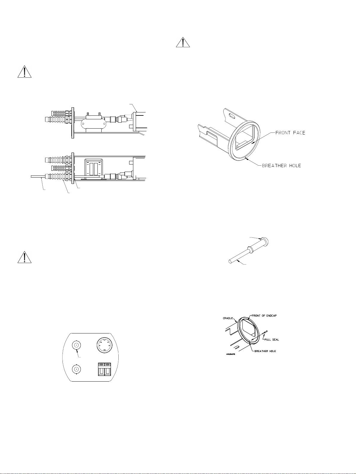
4.1.1 NEMA-3R and IP54
The LTC 9380 Series housings include a “breather” hole in
the front end cap. The “breather” hole prevents the
accumulation of moisture inside the housing when installed in
areas of high humidity. With the “breather” hole open, the
TC9380 Series housings meet the enclosure rating
requirements of NEMA-3R and IP54.
4.1.2 NEMA-4 and IP65
For installations requiring an enclosure rating of NEMA-4 or
IP65, the “breather” hole must be plugged using the “pull
seal” (Part No. 315 2569 001) provided in the hardware kit.
Refer to Final Assembly under INSTALLATION for
proper installation.
5 INSTALLATION
This installation should be made by a qualified
service person and conform to all local codes.
5.1 Model Designation
Model Power Transformer
No. Rated Input Range Output Output
LTC 9383/60 115 VAC, 108 to 132 24 VAC, 30 W
LTC 9383/20 24 VAC, 21.6 to 26.6 24 VAC, 30 W
LTC 9383/10 24 VAC, 21.6 to 26.6 24 VAC, 30 W
LTC 9383/50 230 VAC, 207 to 253 24 VAC, 30 W
LTC 9388/60 115 VAC, 108 to 132 24 VAC, 30 W
LTC 9388/20 24 VAC, 21.6 to 26.6 24 VAC, 30 W
LTC 9388/10 24 VAC, 21.6 to 26.6 24 VAC, 30 W
LTC 9388/50 230 VAC, 207 to 253 24 VAC, 30 W
1. The power transformers included with these housings are used to
provide heater power, and can be used to provide isolated camera
power.
2. Heater requires 10 watts.
Do Not Exceed 30 VAC Input on 24 VAC models.
Operation above 30 VAC violates low voltage operation
(Class 2 Specifications). Normal operation is 24 VAC.
TUV Approved 24 VAC Models
Caution: Use an approved power supply incorporating
reinforced insulation from primary to secondary to isolate
unit from Mains.
Maximum Camera/Lens Size
LTC 9383: Accepts cameras up to 64 W x 53 H mm (2.5 x
2.1 in), lenses up to 67 W x 75 H mm (2.6 x 2.9 in), and
camera/lens combinations up to 252 L (9.9 in).
LTC 9388: Accepts cameras up to 64 W x 53 H mm (2.5 x
2.1 in), lenses up to 67 W x 75 H mm (2.6 x 2.9 in), and
camera/lens combinations up to 353 L (13.9 in).
50/60 Hz 50/60 Hz
50/60 Hz 50/60 Hz
50 Hz 50 Hz
50/60 Hz 50/60 Hz
50/60 Hz 50/60 Hz
50/60 Hz 50/60 Hz
50 Hz 50 Hz
50/60 Hz 50/60 Hz
1
Voltage Power
5.3 Cable Requirements
Video Transmission (Coaxial)
Cable Type: RG-59/U (Runs < 1000 ft)
RG-11/U (Runs < 2000 ft).
Cable Size: Outside diameter between
4.6 mm (0.181”) & 7.9 mm (0.312”).
Cable Shape: Round.
Shield:
Center Conductor: Stranded Copper Center*.
DC Resistance:
Cable Impedence: 75 Ohm*.
Agency Rating: UL.
Environmental: Outdoor rated.
Temperature Rating:
Sources: Belden 9259
2
Input Power Cord - North American
Cable Type: SJTOW-A rated.
Cable Size: Outside diameter between
Cable Shape: Round.
Conductors: 3 conductor version and
Agency Rating: UL/C.S.A., UL VW-1.
Environmental: Outdoor rated.
Temperature Rating: 105
Voltage Rating: 300 V.
Sources: Belden 19506
Input Power Cord - European
Cable Type: H05RN-F3G0.75 and
Cable Size: Outside diameter between
Cable Shape: Round.
Conductors: 3 conductor version and
Agency Rating: VDE.
Environmental: Outdoor rated.
Sources: Olflex 1600252
≥ 93% Braided Copper Shield*.
≤ 15 Ohms/1000 ft* (RG-59/U)
≤ 6 Ohms/1000 ft* (RG-11/U).
≥ 80 °C.
Belden 9238.
4.3 mm (0.170”) & 11.9 mm (0.470”).
2 conductor version.
°C.
Belden 19509
Northwire 573939.
H05RN-F3G1.00.
4.3 mm (0.170”) & 11.9 mm (0.470”).
2 conductor version.
Olflex 1600253.
Page 5
Lens Control Cable
Cable Type: Jacketed Multiconductor Cable.
Cable Size: Outside diameter between
4.3 mm (0.170”) & 11.9 mm (0.470”).
Cable Shape: Round.
Shield: Overall shielding.
Conductors: Stranded 20 to 16 AWG wire.
No. of Conductors: 4 and 8.
Conductor Insulation: Color coded.
Sources: Belden 9552
Belden 9554.
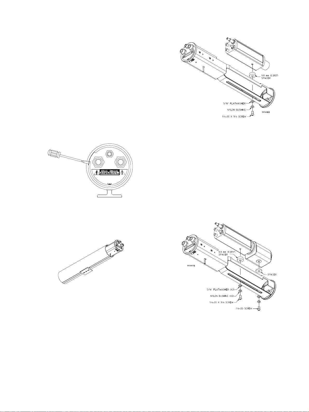
5.4 Cradle Removal
1. Remove the cradle from the housing by removing the
rear retaining ring from the rear cap with the flat blade
screwdriver. Place the screwdriver underneath the
relieved portion of the retaining ring and gently pry
outward. See Figure 1.
S925A02BE
Figure 1: Removing Rear Retaining Ring
2. Remove the cradle assembly by pushing gently on the
metal part of front cap and simultaneously grasping the
fittings and pulling the cradle assembly out of the
housing. Be sure to keep the edges of the end caps clean
and free of scratches. See Figure 2.
1 1/4 inch BHCS, nylon bushing, 5/16-inch flat washer,
and 9.8 mm (0.385 inch) plastic spacer and 7.4 mm
(0.292 inch) plastic spacer. See Figure 3.
Figure 3: Mounting a Fixed Lens Camera
Zoom Lens Cameras: Allow 3/16-inch (5-mm)
clearance from the front face of the lens to the front
faceplate of the cradle during the camera/lens assembly.
This clearance provides the necessary space for the lens
to extend outward when zooming. Secure the
camera/lens to the cradle with appropriate hardware
listed in the fixed lens camera section. Secure the lens to
the cradle with 1/4-20 BHCS, nylon bushing, 5/16-inch
flatwasher, and a plastic spacer. See the table below for
specific screw and spacer. See Figure 4.
Lens 1/4-20 Screw Plastic Spacer
TC1848B 3/8-inch long Not Required
TC9948 5/8-inch long 7.4 mm (0.292 in)
TC9958 1/2-inch long 3.9 mm (0.154 in)
TC9970A 3/8-inch long 0.4 mm (0.016 in)
S925A03DE
Figure 2: Removing Cradle Assembly
5.5 Camera/Lens Installation
With the cradle removed from the housing, follow all of the
steps below.
1. Detach the hardware kit from the inside of the cradle.
2. Place the camera/lens combination into the cradle
assembly.
Fixed Lens Cameras: Position the camera/lens 1 mm
(0.04 in) away from the faceplate. For TC Series
camers, secure the camera/lens to the cradle with 1/420 x 3/4-inch BHCS, nylon bushing, 5/16-inch flatwasher,
and the 9.8 mm (0.385 in) plastic spacer. For LTC 0240
and LTC 0140 Series cameras, use 1/4-20 x 1 1/4 inch
BHCS, nylon bushing, 5/16-inch flat washer, and 9.8 mm
(0.385 inch) plastic spacer, 7.4 mm (0.292 inch) plastic
spacer, and 3.9 mm (0.154 inch) plastic spacer. For
LTC 0430 and LTC 0450 Series cameras, use 1/4-20 x
Figure 4: Mounting a Zoom Lens Camera
Page 6

5.6 Camera/Lens Wiring
WARNING: Only use the cables specified
under “INSTALLATION, Cable
Requirements” for wiring of all cameras and
lenses.
5.6.1 General
1. The dual-male threaded portion of the three liquid tight
fittings, two NPT 1/2-inch and one NPT 3/8-inch,
located in the rear of the cradle are provided preinstalled. Do not remove or loosen these parts. They
have been installed to a specified torque to prevent
entrance of water. The two large fittings are supplied
with seal glands for cables with diameters from 4.3 mm
(0.17 in) to 11.9 mm (0.47 in). The small fitting will
accept cables with diameters from 4.6 mm (0.181 in) to
7.9 mm (0.312 in). See Figure 5 and 6.
Be sure to securely tighten all fittings to
ensure a liquid-tight seal. Failure to do so
could allow water to enter the housing
and damage the camera and lens.
Dual Male Portion
Flexible
Portion
Figure 7: Examples of Drip Loops
5.6.2 Plug Insertion
If no lens control or feed-through wiring will be used,
remove the pre-installed 3/8-inch liquid-tight fitting from the
small top center hole and install the 3/8-inch NPT plug
provided. Use a 5/16-inch (or 8 mm) hex wrench to tighten.
Failure to do so will allow water to enter and cause damage
to all electronic parts. See Figure 8.
Seal Gland
S925A08BE
Figure 5: Liquid Tight Fitting Assembly
Figure 6: Liquid Tight Fitting Detail
If a sealant is to be used, be sure it is a neutral cure
type. Sealants that release acetic acid may harm camera
electronics.
If it is necessary to use PG type conduit, a NPT to PG
conversion kit (TC9380PG) can be purchased
separately.
Use of “drip loops” is recommended on
the wiring outside of the rear end cap.
See Figure 7.
Figure 8: 3/8-inch NPT Plug Insertion
5.6.3 Power Connections
The LTC 9380 Series housings offer the user one of three
transformer voltage configurations. The suffix to the
housing model number will determine the type of
transformer and supply voltage required.
The LTC 9380 Series allow the use of 24 VAC cameras
regardless of the supply voltage to the housing This is
achieved through the use of a transformer in the housing.
Each transformer provides a 24 VAC supply for the camera
power from its secondary. The transformer's primary supply
power will vary dependent upon the model housing, see
Model Designation. In the 115 volt and 230 volt models,
the transformer also supplies 24 VAC power to the integral
window heater/defogger.
Refer to the following model housing sections for your
model wiring procedure.
Power connection into the housings is to be supplied
through a minimum type UL Standard "SJ" cord acceptable
for outdoor use. Installation must conform to acceptable
NEC and local codes. Use the Recommended Maximum
Cable Lengths chart for selecting the proper wire size
used.
Page 7

Recommended Maximum Cable Lengths
Models Wire Size Distance
-1 (115 VAC) 1.5 16 1200 4000
-2 (24 VAC) 0.5 22 45 150
-2X (24 VAC) 0.5 20 75 250
-4 (230 VAC) 1.5 16 2000 6600
1. Use the left liquid-tight fitting of the housing to route the power wire
into the housing. See Figure 9.
2
mm
2.5 14 1700 5700
4 12 3000 10,000
1 18 120 400
1.5 16 200 700
2,5 14 330 1100
2.5 14 3200 10,500
4 12 5280 17,350
AWG meters feet
Figure 9: Liquid-Tight Fittings and Power Connector
(Side & Top Views)
2. A screw/terminal lug is provided for securing a safety
ground. To attach the safety grounding wire (green
115 volt, green/yellow 230 volt), first unscrew the
terminal lug and strip and crimp the grounding wire into
the lug. Next pull the grounding wire through the larger
rear hole and attach the terminal lug to the cradle using
the M4 x 10 screw provided. See Figure 10.
Cradle
Failure to do so will allow water to enter and damage all
electronic parts. Use a tie wrap (included) to provide
strain relief on the power cord at the exit point (inside
unit). See Figures 17 and 18 for an example.
Be sure to securely tighten all fittings to
ensure a liquid-tight seal. Failure to do so
could allow water to enter the housing
and damage the camera and lens.
5.6.4 LTC 9383/60, LTC 9388/60 Housings
These housings require connection to 115 VAC, and are
designed to be used where site power is 115 volts.
The LTC 9383/60 and LTC 9388/60 housings can easily be
used with either 115 volt or 24 volt cameras.
The internal transformer provides 24 VAC for both the
heater/defogger and 24 volt camera power. The
transformer will provide flying leads for connection to the
primary (white wire/pin 1, black wire/pin 6) and the
secondary (white/black striped wires-pins 7 and 12). The
housing is shipped with the heater/defogger
connected to the secondary. No installer interface is
required. See Figure 9.
Installing a 115 volt camera into the LTC 9383/60 or
LTC 9388/60 housing requires the camera's line cord to be
cut and connected with the transformer primary leads and
the power supply line. See Figure 11.
1. Cut the power cord leaving enough cable to allow
connection to the primary (approximately 5 inches).
Strip no less than 6 mm (0.25 in) and no more than
8 mm (0.31 in) of insulation away from the wire, be sure
not to nick the wires. Connect the supply line to the
camera power cord and transformer primary leads. Use
the wire nuts provided for this connection.
2. The secondary flying leads (white/black striped) will not
be used in this application and should be taped to
prevent shorting. See wiring diagram Figure 11 for
clarification and Figure 9 for power connection
drawings.
To Heater/Defogger
White/Black
Striped
24 VAC
No Connection
Red
Black
115 VAC
Input
To Camera
Large
Rear
Hole
Safety
Grounding
Wire
M4 Screw
Terminal Lug
S925A15AE
Figure 10: Securing Ground Wire
3. Pull any excess wire out of the cradle assembly and
tighten the fitting to 8.5 N-m to 9.0 N-m (75 in-lb to
80 in-lb). This torque rating is approximately 1 to 1 1/2
turns past the point the fitting starts to grip the wire.
White
To Camera
White/Black
Striped
To Heater/Defogger
Red
S925A10AE
Figure 11: LTC 9383/60/LTC 9388/60 Transformer
Wired for 115 Volt Camera
Installing a 24 volt camera into the LTC 9383/601 or
LTC 9388/60 housing utilizes the internal transformer for
camera power. See Figure 11.
1. Connect the supply (115 VAC) to the primary flying
leads of the transformer (white wire/pin 1, black
wire/pin 6). Use the wire nuts provided for this
connection.
2. Connect the secondary flying leads (white/black striped
wires-pins 7 and 12) to the camera's 24 volt input. See
wiring diagram Figure 12 for clarification and Figure 9
for power connection drawings.
Page 8

To Heater/Defogger
Red
To Camera
Red
S925A12AE
Black
115 VAC
Input
White
White/Black
Striped
24 VAC
White/Black
Striped
To Heater/Defogger
Figure 12: LTC 9383/60/LTC 9388/60 Transformer
Wired for 24 Volt Camera
5.6.5 LTC 9383/20 and L TC 9388/20 Housings
These housings are to be connected to 24 VAC only,
and are designed to be used where site power is 24
volts.
Use only where IEC (CE) approval is NOT
required. If IEC approval is required use /10
or /50 versions.
The LTC 9383/20 and LTC 9388/20 are designed to
be used with 24 volt cameras only.
Connection of these housings to supply voltage in
excess of a nominal 24 VAC source will cause
damage.
The internal isolation transformer provides 24 VAC for
camera power. The transformer provides flying leads for
connection to the primary (white wire/pin 1, black wire/pin
6) and the secondary (white/black striped wires-pins 7 and
12). The housing is shipped with the heater/defogger
connected to the primary. No installer interface is
required. See Figure 13.
1. Connect the supply (24 VAC) to the primary flying leads
of the transformer. Use the wire nuts provided for this
connection. See Figure 13.
2. Connect the secondary flying leads to the camera's
24 volt input. See wiring diagram Figure 13 for
clarification and Figure 9 for power connection
drawings.
To Heater/Defogger
Black
24 VAC
Input
White
White/Black
Striped
24 VAC
White/Black
Striped
To Heater/Defogger
Red
To Camera
Red
S925A13AE
Figure 13: LTC 9383/20/LTC 9388/20 Transformer
Wired for 24 Volt Camera
5.6.6 LTC 9383/10 and LTC 9388/10 Housings
These housings are to be connected to 24 VAC only,
and are designed to be used where site power is
24 volts.
Use where IEC (CE) approval is required.
The LTC 9383/10 and LTC 9388/10 are designed to
be used with 24 volt, 50 Hz cameras only.
Connection of these housings to supply voltage in
excess of 30 VAC source will cause damage.
Do not remove the transformer insulator.
No user serviceable parts are underneath.
The internal isolation transformer provides 24 VAC for
camera power. A terminal block provides connection to the
transformer via leads to the primary (blue wire/blue
terminal/pin 1, black/fuse/grey terminal/pin 6). The
transformer secondary is white/black striped wires on pins 7
and 12. The housing is shipped with the
heater/defogger connected to the secondary. No
installer interface is required. See Figure 14.
1. Connect the supply (24 VAC) to the terminal blocks.
Use only the terminal block provided for this
connection. See Figure 14.
2. Connect the secondary flying leads to the camera's
24 volt input. See wiring diagram Figure 14 for
clarification and Figure 9 for power connection
drawings.
Brown
24 VAC
Input
Blue
Grey
Terminal
Blue
Terminal
Black
Blue
To Heater/Defogger
White/Black
Striped
White/Black
Striped
To Heater/Defogger
Red
To Camera
Red
W9606400AE
Figure 14: LTC 9383/10/LTC 9388/20 Transformer
Wired for 24 Volt Camera
5.6.7 LTC 9383/50,L TC9388/50 Housings
These housings require connection to 230 VAC, and are
designed to be used where site power is 230 volts.
The LTC 9383/50 and LTC 9388/50 housings can easily be
used with either 230 volt or 24 volt cameras.
The internal transformer provides 24 VAC for both the
heater and 24 volt camera power. A terminal block provides
connection to the transformer via leads to the transformer
primary (blue wire/blue terminal/pin 1, black/fuse/grey
terminal/pin 6). The transformer secondary is white/black
striped wires on pins 7 and 12. The housing is shipped
with the heater/defogger connected to the
secondary. No installer interface is required.
Do not remove the transformer insulator.
No user serviceable parts are underneath.
Installing a 230 volt camera into the LTC 9383/50 or
LTC 9388/50 housing requires the camera's line cord to be
cut and connected with the transformer's primary wiring and
the power supply line. See Figure 15.
1. Cut the power cord leaving enough cable to allow
connection to the primary (approximately 5 inches).
Strip no less than 6 mm (0.25 in) and no more than
8 mm (0.31 in) of insulation away from the wire, be sure
not to nick the wires. Connect the supply line to the
camera power cord and transformer primary leads. Use
only the terminal block provided for this connection.
2. The secondary flying leads (white/black striped) will not
be used in this application and should be taped to
prevent shorting. See wiring diagram Figure 15 for
clarification and Figure 9 for power connection
drawings.
Page 9

Brown
Grey Terminal Black
To Camera To Heater/Defogger
White/Black
Striped
Use of “drip loops” is recommended on
the wiring outside of the rear end cap.
See Figure 7.
230 VAC Input
Blue Terminal
Blue
Blue
To Camera
24 VAC
White/Black
Striped
To Heater/Defogger
No Connection
S925A11BE
Figure 15: LTC 9383/50/LTC 9388/50 Transformer
Wired for 230 Volt Camera
Installing a 24 volt camera into the LTC 9383/50 or
LTC 9388/50 housing utilizes the internal transformer for
camera power. See Figure 16.
1. Connect the supply (230 VAC) to the terminal block.
Use only the terminal block provided for this
connection.
2. Connect the secondary flying leads to the camera's 24
volt input. Refer to the wiring diagram for clarification.
To Heater/Defogger
Brown
230 VAC
Input
Blue
White/Black
Striped
24 VAC
White/Black
Striped
To Heater/Defogger
Red
To Camera
Red
S925A14AE
Figure 16: LTC 9383/50/LTC 9388/50 Transformer
Wired for 24 Volt Camera
5.7 Video Coax Connection
WARNING: Only use the cables specified
under “INSTALLATION, Cable
Requirements” for wiring of the video coax
connection.
If no lens control or feed-through wires will be used:
1. Install the long flexible portion of the large liquid tight
fitting on the video coax cable and pull the cable through
the right fitting on the rear end of the cradle. Refer
to Figure 17.
2. Attach BNC connector to the coax and connect it to
the camera. Pull any excess wire out of the cradle
assembly and tighten the fitting to 8.5 N-m to 9.0 N-m
(75 in-lb to 80 in-lb). This torque rating is
approximately 1 to 1 1/2 turns past the point the fitting
starts to grip the wire. Failure to do so will result in
water damage to all electronic parts. Use a tie wrap
(included) to provide strain relief on the video cable at
the exit point (inside unit).
3. Install the 3/8-inch NPT plug provided in the unused,
small top center NPT hole. Refer back to Figure 7.
Be sure to securely tighten all fittings to
ensure a liquid-tight seal. Failure to do so
could allow water to enter the housing
and damage the camera and lens.
Figure 17: Video Coax Connection For No Lens
Control Applications (Side & Top Views)
If lens control or feed-through wires will be used:
1. Install the long flexible portion of the small liquid tight
fitting on the video coax cable and pull the cable through
the small fitting on the rear end of the cradle. See
Figure 18.
2. Attach the BNC connector to the coax and connect it
to the camera. Pull any excess wire out of the cradle
assembly and tighten the fitting to 4.0 N-m to 4.5 N-m
(35 in-lb to 40 in-lb). This torque rating is
approximately 1 to 1 1/2 turns past the point the fitting
starts to grip the wire. Failure to do so will result in
water damage to all electronic parts. Use a tie wrap
(included) to provide strain relief on the video cable at
the exit point (inside unit).
CCD Camera
BNC Connector
Small Fitting
Tie Wrap
S925A16BE
Figure 18: Video Coax Connection For Lens
Control Applications (Side & Top Views)
5.8 Lens Wiring
WARNING: Only use the cables specified
under “INSTALLATION, Cable
Requirements” for wiring of the lens.
1. If installing a zoom lens, insert the lens control cable
with installed flexible fitting in through the right fitting
at the rear of the cradle. Attach the lens wiring to the
lens mating connector and connect it to the lens. If
mating connector is not available, connect directly to the
lens cable. Pull any excess wire out of the cradle
assembly and tighten the fitting to 8.5 N-m to 9.0 N-m
(75 in-lb to 80 in-lb). This torque rating is
Page 10
approximately 1 to 1-1/2 turns past the point the fitting
starts to grip the wire. Failure to do so will result in
water damage to all electronic parts. Use a tie wrap
(included) to provide strain relief on the lens control
cable at the exit point (inside unit). See Figure 19.
NOTE: See specification on lens cord for correct plug
connection.
Be sure to securely tighten all fittings to
ensure a liquid-tight seal Failure to do so
could allow water to enter the housing and
damage the camera and lens.
CCD Camera
Lens Zoom Focus Connectors
S925A17BE
Lens
Control
Cable
Right
Fitting
Tie Wrap
Figure 19: Lens Control Cable Wiring
(Side & Top Views)
2. If using a pan/tilt with a feed through cable, insert
the camera/lens function cable in through the right
fitting at the rear of the cradle. Wire the functions, as
described above or as needed.
Use of “drip loops” is recommended on the
wiring outside of the rear end cap. See
Figure 7.
5.9 Camera/Lens Adjustment
1. Verify camera and lens operation before final assembly
of the cradle into the housing. Adjust the camera focus
and iris as necessary. See individual camera instructions.
2. If the camera includes an unused synchronization circuit,
install a 75 ohm BNC termination resistor on camera
"SYNC IN" terminal. See Figure 20.
Rear Of Camera
5.10 Final Assembly
5.10.1 Pull Seal Installation
If the “breather” hole is open, do NOT
mount the housing in a position where the
front end cap is pointed upward.
To maintain enclosure protection ratings of NEMA-4 and
IP65, the pull seal (provided in the hardware kit) must be
installed in the front end cap. It is recommended that the
pull seal be installed in a cool, dry environment to prevent
trapping moisture inside the housing. See Figure 21.
Note: Pull seal installation allows the housing’s front end cap
to be pointed upward.
W9608405A
Figure 21: Breather Hole
Proper installation of the pull seal is as follows:
1. With the cradle assembly removed from the housing,
remove the front retaining ring.
2. Obtain a rubber pull seal from the hardware kit (Part
Number 315 2569 001). An extra pull seal is also
provided. See Figure 22.
HEAD
W9608406AE
Figure 22: Pull Seal
3. Insert the “long end” of the pull seal into the breather
hole starting from the front side of the endcap. See
Figure 23.
"LONG END"
Sync In
S927A02AE
Figure 20: Sync Connection
Figure 23: Inserting the Pull Seal
4. Grip the pull seal’s “long end” from the back of the
front endcap. Steadily pull the “long end” until the head
of the pull seal is flat against the front of the endcap.
See Figure 24.
Note: The Pull Seal’s “long end” will stretch
when pulled through the breather hole.
Page 11

W9608408AE
W9608409AE
Figure 24: Installing the Pull Seal
5.10.2 Cradle Assembly
1. Position the housing vertically and replace the cradle
assembly by applying pressure onto the rear cap until
the end of the cradle is securely closed. Make sure
the index marks are aligned with the etch mark on
the housing. See Figure 25.
Etch Marks
(x4 at 90°)
Index Marks S925A18DE
Figure 25: Inserting Cradle Assembly
CAUTION: If a pull seal is installed in the
breather hole, be careful not to pinch the
head of the pull seal. Damage to the pull seal
may allow water to enter the housing causing
damage to the camera and lens.
If the pull seal was installed as described under Pull Seal
Installation, continue with step 2.
If the pull seal was not installed, skip to step 3.
2. Install the front retaining ring so the pull seal is centered
in the retaining ring gap. See Figure 26.
Figure 26: Positioning the Front Retaining Ring
3. Replace the rear retaining ring by inserting it into the
housing groove. This secures the cradle assembly in the
housing. If the housing needs to be tamper resistant, the
TC9380TK (purchased separately) should be installed at
this time.
4. Attach the housing to the appropriate mount or pan/tilt
using instructions provided. According to the
orientation of the housing, the cradle assembly may
need rotating. To rotate the cradle assembly (while
mounted), grasp the fittings and rotate to the desired
position using the index marks as reference. View the
monitor while rotating. See Figure 27.
WARNING: If the cradle is rotated, the front retaining ring
must also be rotated. Position the front retaining ring so the
breather hole is centered in the retaining ring gap.
S925A19EE
Figure 27: Rotating Cradle Assembly
CAUTION: If a pull seal is installed in the
breather hole, do not pinch the head of the
pull seal. Damage to the pull seal may allow
water to enter the housing causing damage
to the camera and lens.
Page 12

6 RECOMMENDED APPLICATIONS
6.1 LTC 9383/60 and LTC 9388/60 Housings
The LTC 9383/60 and LTC 9388/60 housings are UL Listed to Standard 2044. Only the following cameras can be used in
these housings to maintain the UL Listing. These housings require a 115 VAC, 60 Hz power supply.
Camera Suggested Lenses
Models
LTC 0142/20, LTC 0142/60 with 3mm fixed iris lens 3mm fixed iris lens
LTC 0143/20, LTC 0143/60 with 6mm fixed iris lens 6mm fixed iris lens.
LTC 0242/20, LTC 0242/60 with 3mm fixed iris lens 3mm fixed iris lens
LTC 0243/20, LTC 0243/60 with 6mm fixed iris lens 6mm fixed iris lens.
LTC 0330/20 Fixed, TC9938, TC9948 Fixed, TC9938, TC9948A, TC1848B
LTC 0350/20 Fixed, TC9938, TC9948 Fixed, TC9938, TC9948A, TC1848B
LTC 0430/20 Fixed, TC9938, TC9948 Fixed, TC9938, TC9948A, TC1848B
LTC 0450/20 Fixed, TC9938, TC9948 Fixed, TC9938, TC9948A, TC1848B
TC351A, TC352A Fixed Fixed, TC9948A, TC1848B
TC361, TC362 Fixed, TC9948A
TC371, TC372 Fixed, TC9938, TC9948A, TC1848B
TC381, TC382 Fixed, TC9948A
TC391, TC392 Fixed, TC9938, TC9948A, TC1848B
TC551A Fixed Fixed, TC9938, TC9948A, TC1848B
TC552A Fixed, TC9938, TC9948A, TC1848B
TC591, TC592 Fixed, TC9938, TC9948A, TC1848B
TC651B, TC652BT Fixed Fixed, TC9948A, TC1848B
TC652B Fixed, TC9948A
TC952, TC972 Fixed (manual iris only) Fixed (manual iris only)
_____________________________________________________________________________________________
LTC 9383/60 LTC 9388/60
1
1
, TC1848B
1
, TC1848B
1
, TC1848B1 Fixed , TC9948A, TC1848B1, TC9970A
1
1
1
, TC9958
1
, TC9958
1
, TC9958
1
, TC9958
1
1
1
1
Fixed, TC9948A, TC1848B1, TC9970A
Fixed, TC9938, TC9948A, TC1848B1, TC99581, TC9970A
Fixed, TC9948A, TC1848B1, TC9970A
Fixed, TC9938, TC9948A, TC1848B1, TC99581, TC9970A
Fixed, TC9938, TC9948A, TC1848B1, TC9958
Fixed, TC9938, TC9948A, TC1848B1, TC99581, TC9970A
, TC9970A
1
, TC9970A
1
, TC9958
1
, TC9958
1
, TC9958
1
, TC9958
1
, TC99581, TC9970A
1
, TC9970A
1
, TC9970A
1
, TC9970A
1
, TC9970A
1
, TC9970A
1. Also applies to models with pre-position
option denoted by a suffix "P".
6.2 LTC 9383/20 and LTC 9388/20 Housings
The LTC 9383/20 and LTC 9388/20 Housings are UL Listed to Standard 2044. Only the following cameras can be used in
these housings to maintain the UL Listing. These Housings require a 24 VAC, 60 Hz power supply.
Camera Suggested Lenses
Models
LTC 0142/20 with 3mm fixed iris lens 3mm fixed iris lens
LTC 0143/20 with 6mm fixed iris lens 6mm fixed iris lens.
LTC 0242/20 with 3mm fixed iris lens 3mm fixed iris lens
LTC 0243/20 with 6mm fixed iris lens 6mm fixed iris lens.
LTC 0330/20 Fixed, TC9938, TC9948 Fixed, TC9938, TC9948A, TC1848B
LTC 0350/20 Fixed, TC9938, TC9948 Fixed, TC9938, TC9948A, TC1848B
LTC 0430/20 Fixed, TC9938, TC9948 Fixed, TC9938, TC9948A, TC1848B
LTC 0450/20 Fixed, TC9938, TC9948 Fixed, TC9938, TC9948A, TC1848B
TC352A, TC652BT Fixed Fixed, TC9948A, TC1848B
TC362, TC382 Fixed, TC9948A
TC372, TC392 Fixed, TC9938, TC9948A, TC1848B
TC552A, TC592 Fixed, TC9938, TC9948A, TC1848B
TC652B Fixed, TC9948A
TC952, TC972 Fixed (manual iris only) Fixed (manual iris only)
1. Also applies to models with pre-position option denoted by a suffix "P".
_____________________________________________________________________________________________
LTC 9383/20 LTC 9388/20
1
1
, TC1848B
1
, TC1848B1 Fixed, TC9948A, TC1848B1, TC9970A
1
1
, TC9958
1
, TC9958
1
1
Fixed, TC9948A, TC1848B1, TC9970A
Fixed, TC9938, TC9948A, TC1848B1, TC99581, TC9970A
Fixed, TC9938, TC9948A, TC1848B1, TC9958
, TC9970A
1
, TC9958
1
, TC9958
1
, TC9958
1
, TC9958
1
, TC9970A
1
, TC9970A
1
, TC9970A
1
, TC9970A
1
, TC9970A
Page 13

6.3 LTC 9383/10 and LTC 9388/10 Housings
The LTC 9383/10 and LTC 9388/10 housings will accommodate the following cameras. These Housings require a 24 VAC,
50 Hz power supply. They are not UL Listed.
Camera Suggested Lenses
Models
LTC 0142/10 with 3mm fixed iris lens 3mm fixed iris lens
LTC 0143/10 with 6mm fixed iris lens 6mm fixed iris lens.
LTC 0242/10 with 3mm fixed iris lens 3mm fixed iris lens
LTC 0243/10 with 6mm fixed iris lens 6mm fixed iris lens.
LTC 0330/20 Fixed, TC9938, TC9948 Fixed, TC9938, TC9948A, TC1848B
LTC 0350/20 Fixed, TC9938, TC9948 Fixed, TC9938, TC9948A, TC1848B
LTC 0430/20 Fixed, TC9938, TC9948 Fixed, TC9938, TC9948A, TC1848B
LTC 0450/20 Fixed, TC9938, TC9948 Fixed, TC9938, TC9948A, TC1848B
TC352AX, TC652BTX Fixed Fixed, TC9948A, TC1848B
TC362X, TC382X Fixed, TC9948A
TC372X, TC392X Fixed, TC9938, TC9948A, TC1848B
TC552AX, TC592X Fixed, TC9938, TC9948A, TC1848B
TC652BX Fixed , TC9948A
TC952X, TC972X Fixed (manual iris only) Fixed (manual iris only)
1. Also applies to models with pre-position option denoted by a suffix "P".
_____________________________________________________________________________________________
LTC 9383/20 LTC 9388/10
1
, TC1848B
1
, TC1848B
1
, TC9958
1
, TC9958
1
, TC9958
1
1
1
1
, TC9958
1
, TC9958
1
1
1
Fixed, TC9948A, TC1848B1, TC9970A
Fixed, TC9938, TC9948A, TC1848B1, TC99581, TC9970A
Fixed, TC9938, TC9948A, TC1848B1, TC9958
Fixed, TC9948A, TC1848B1, TC9970A
, TC9970A
, TC9958
1
, TC9970A
1
, TC9970A
1
, TC9970A
1
, TC9970A
1
, TC9970A
6.4 LTC 9383/50 and LTC 9388/50 Housings
The LTC 9383/50 and LTC 9388/50 housings will accommodate the following cameras. These Housings require a 230 VAC,
50 Hz power supply. They are not UL Listed.
Camera Suggested Lenses
Models
LTC 0142/10, LTC 0142/50 3mm fixed iris lens 3mm fixed iris lens
LTC 0143/10, LTC 0143/50 6mm fixed iris lens 6mm fixed iris lens.
LTC 0242/10, LTC 0242/50 3mm fixed iris lens 3mm fixed iris lens
LTC 0243/10, LTC 0243/50 6mm fixed iris lens 6mm fixed iris lens.
LTC 0330/20 Fixed, TC9938, TC9948 Fixed, TC9938, TC9948A, TC1848B
LTC 0350/20 Fixed, TC9938, TC9948 Fixed, TC9938, TC9948A, TC1848B
LTC 0430/20 Fixed, TC9938, TC9948 Fixed, TC9938, TC9948A, TC1848B
LTC 0450/20 Fixed, TC9938, TC9948 Fixed, TC9938, TC9948A, TC1848B
TC352AX, TC652BTX Fixed Fixed, TC9948A, TC1848B
TC354AX, TC654BX Fixed Fixed, TC9948A, TC1848B
TC362X, TC382X Fixed, TC9948A
TC364X, TC384X Fixed, TC9948A
TC372X, TC392X Fixed, TC9938, TC9948A, TC1848B
TC374X, TC394X Fixed, TC9938, TC9948A, TC1848B
TC552AX, TC592X Fixed, TC9938, TC9948A, TC1848B
TC554AX Fixed Fixed, TC9938, TC9948A, TC1848B
TC594X Fixed, TC9938, TC9948A, TC1848B
TC652BX Fixed, TC9948A
TC952X, TC972X Fixed (manual iris only) Fixed (manual iris only)
1. Also applies to models with pre-position option denoted by a suffix "P".
Suggested CS-Mount, Fixed, Auto-Iris, and Zoom Lenses (1/2-inch and 1/3-inch cameras, except TC952 and TC972 Series)
TC9902: 1/3-inch 2.8 mm, f/1.2, fixed TC9921A: 1/2-inch 3.8 mm, f/0.8, fixed
TC9904: 1/3-inch 4 mm, f/1.2, fixed TC9922A: 1/2-inch 6 mm, f/0.75, fixed
TC9908: 1/3-inch 8 mm, f/1.2, fixed TC9923A: 1/2-inch 12 mm, f/0.8, fixed
TC9903A: 1/2-inch 3.7 mm, f/1.6, fixed TC9938: 1/3-inch 3.8-38 mm, f/1.2, 10X zoom
TC9906A: 1/2-inch 6 mm, f/1.4, fixed TC9958
TC9907A: 1/2-inch 7 mm, f/1.4, fixed TC9948A: 1/2-inch 8-48 mm, f/1.4, 6X zoom
TC9912A: 1/2-inch 12 mm, f/1.4, fixed TC1848B
TC9913A: 1/2-inch 12 mm, f/1.4, fixed TC9970A: 1/2-inch 7.5-75 mm, f/1.4, 10X zoom
_____________________________________________________________________________________________
LTC 9383/50 LTC 9388/50
1
, TC9970A
1
1
, TC1848B
1
, TC1848B
1
, TC1848B1 Fixed, TC9948A, TC1848B1, TC9970A
1
1
1
, TC9958
1
, TC9958
1
, TC9958
1
, TC9958
1
: 1/3-inch 5.8-58 mm, f/1.2, 10X zoom
1
: 1/2-inch 8-48 mm, f/1.0, 6X zoom
1
1
1
1
Fixed, TC9948A, TC1848B1, TC9970A
Fixed, TC9948A, TC1848B1, TC9970A
Fixed, TC9938, TC9948A, TC1848B1, TC99581, TC9970A
Fixed, TC9938, TC9948A, TC1848B1, TC99581, TC9970A
Fixed, TC9938, TC9948A, TC1848B1, TC9958
Fixed, TC9938, TC9948A, TC1848B1, TC99581, TC9970A
, TC9970A
1
, TC9958
1
, TC9958
1
, TC9958
1
, TC9958
1
, TC99581, TC9970A
1
, TC9970A
1
, TC9970A
1
, TC9970A
1
, TC9970A
1
, TC9970A
Suggested CS-Mount, Manual Iris, Fixed Lenses (1/3-inch cameras)
TC9702: 1/3-inch 2.8 mm, f/1.3
TC9704: 1/3-inch 4 mm, f/1.2
TC9708: 1/3-inch 8 mm, f/1.2
TC9712: 1/2-inch 12 mm, f/1.4
Page 14
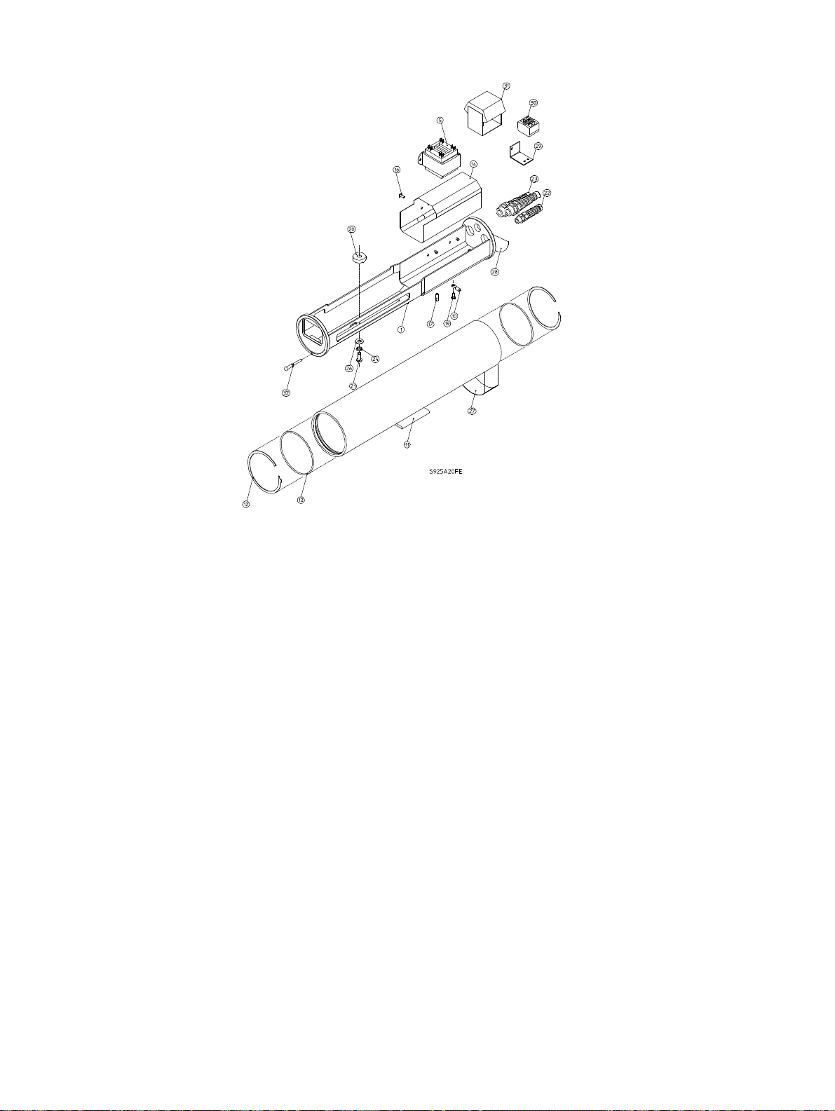
7 EXPLODED VIEW
8 PARTS LIST
Ref Drawing
No. Number Qty. Part Description
15-inch Cradle Assembly Kit - 315 2798 001
1 - 1 15-inch Cradle-Heater Assembly
10 - 1 Ring Tongue Terminal
14 - 1 15-inch Plastic Sheild
17 - 1 Ground Spring
19 - 1 M4 x 10 Phillips Head Screw
28 - 1 Caution Label
19-inch Cradle Assembly Kit - 315 2799 001
1 - 1 19-inch Cradle-Heater Assembly
10 - 1 Ring Tongue Terminal
14 - 1 19-inch Plastic Sheild
17 - 1 Ground Spring
19 - 1 M4 x 10 Phillips Head Screw
28 - 1 Caution Label
115 VAC PreWired Transformer Kit - 315 2800 001
5 - 1 115 VAC Prewired Transformer
16 - 2-3 Rivet, 5/16-inch
24 VAC Prewired Transformer Kit - 315 2801 001
5 - 1 24 VAC Prewired Transformer Kit
16 - 2-3 Rivet, 5/16-inch
29 - 1 Bracket (-/10, -/50 models only)
30 - 1 Connector (-/10, -/50 models only)
31 - 1 Transformer Insulator (-/10, -/50
230 VAC Prewired Transformer Kit - 315 2802-001
5 - 1 230 VAC Prewired Transformer Kit
16 - 2-3 Rivet, 5/16-inch
29 - 1 Bracket (-/10, -/50 models only)
30 - 1 Connector (-/10, -/50 models only)
31 - 1 Transformer Insulator (-/10, -/50
15-inch Housing Kit - 315 2803 001
11 - 1 15-inch Housing
12 315 1556 900 2 Retaining Ring
13 315 1557 903 2 Silicone O-Ring
27 - 1 ID Label
19-inch Housing Kit - 315 2804 001
11 - 1 19-inch Housing
12 315 1556 900 2 Retaining Ring
13 315 1557 903 2 Silicone O-Ring
27 - 1 ID Label
models only)
models only)
HARDWARE KITS
Ref Drawing
No. Number Qty. Part Description
Hardware Kit - 315 1514 001 (-/10, -/50 models only)
- - 3 Cable Tie
20 - 1 9.8 mm Plastic Spacer
20 - 2 7.4 mm Plastic Spacer
20 - 1 3.9 mm Plastic Spacer
20 - 1 0.4 mm Plastic Spacer
21 - 1 1/4-20 x 3/8-inch Button Head Screw
21 - 3 1/4-20 x 1/2-inch Button Head Screw
21 - 1 1/4-20 x 5/8-inch Button Head Screw
21 - 1 1/4-20 x 3/4-inch Button Head Screw
21 - 1 1/4-20 x 1 1/4-inch Button Head Screw
- - 1 3/8-inch NPT Plug
22 - 1 Small Flex Fitting
23 - 2 Large Flex Fitting
24 - 2 Nylon Bushing
26 - 2 5/16-inch Flat Washer
32 - 2 Rubber Pull Seal
Hardware Kit - 315 1514 002 (-/60, -/20 models only)
- - 3 Cable Tie
20 - 1 9.8 mm Plastic Spacer
20 - 2 7.4 mm Plastic Spacer
20 - 1 3.9 mm Plastic Spacer
20 - 1 0.4 mm Plastic Spacer
21 - 1 1/4-20 x 3/8-inch Button Head Screw
21 - 3 1/4-20 x 1/2-inch Button Head Screw
21 - 1 1/4-20 x 5/8-inch Button Head Screw
21 - 1 1/4-20 x 3/4-inch Button Head Screw
21 - 1 1/4-20 x 1 1/4-inch Button Head Screw
- - 2 Wire Nut
- - 1 3/8-inch NPT Plug
22 - 1 Small Flex Fitting
23 - 2 Large Flex Fitting
24 - 2 Nylon Bushing
26 - 2 5/16-inch Flat Washer
32 - 2 Rubber Pull Seal
Page 15

9380 Series
Outdoor Camera Housings
Addendum
Installation Instructions
Page 16

ADDENDUM
This Addendum applies to all language versions of the
LTC 9380 Series Instructions (3935 890 06581 and
3935 890 06591-CH).
5 INSTALLATION
5.1 Model Designation
Change the voltage ranges for the LTC 9383/60 and
LTC 9388/60 at the 115 VAC Rated Input:
FROM: 108 to 132.
TO: 104 to 127.
3935 890 19611 99-14 1999 Philips Electronics N.V.
Printed In U.S.A. 1999 Philips Communications & Security Systems Inc.
All Rights Reserved. Philips is a registered trademark of
Philips Electronics N.V.
Data subject to change without notice
5.5 Camera/Lens Installation
Add to step3:
For the: LTC 0330/x1,LTC 0350/x1,LTC0430/x1,LTC 0450/x1
cameras, use 1/4-20 x 5/8-inch screw and a 7.4 mm (0.292 in)
plastic spacer, and nylon bushing, 5/16-inch flat washer.
 Loading...