

Philips LTC2632/50, LTC2631/50, LTC2622/50 User Manual
LTC 2600 Series
Video Multiplexers
Instructions For Use


3
IMPORTANT SAFEGUARDS
1. Read Instructions - All the safety and operating instructions should be
read before the unit is operated.
2. Retain Instructions - The safety and operating instructions should be
retained for future reference.
3. Heed Warnings - All warnings on the unit and in the operating
instructions should be adhered to.
4. Follow Instructions - All operating and use instructions should be
followed.
5. Cleaning - Unplug the unit from the outlet before cleaning.Do not
use liquid cleaners or aerosol cleaners.Use a damp cloth for cleaning.
6. Attachments - Do not use attachments not recommended by the
product manufacturer as they may cause hazards.
7. Water and Moisture - Do not use this unit near water - for example,
near a bath tub,wash bowl, kitchen sink,or laundr y tub, in a wet
basement,near a swimming pool, in an unprotected outdoor
installation,or any area which is classified as a wet location.
8. Accessories - Do not place this unit on an unstable stand,tripod,
bracket,or mount. The unit may fall, causing serious injury to a person
and serious damage to the unit.Use only with a stand, tripod, bracket,
or mount recommended by the manufacturer,or sold with the
product.Any mounting of the unit should follow the manufacturer's
instructions,and should use a mounting accessor y recommended by
the manufacturer.
An appliance and cart combination should be moved with
care.Quick stops, excessive force,and uneven surfaces may
cause the appliance and cart combination to overturn.
9. Ventilation - Openings in the enclosure, if any,are provided for
ventilation and to ensure reliable operation of the unit and to protect
it from overheating.These openings must not be blocked or covered.
This unit should not be placed in a built-in installation unless proper
ventilation is provided or the manufacturer's instructions have been
adhered to.
10. Power Sources - This unit should be operated only from the type of
power source indicated on the marking label.If you are not sure of
the type of power supply you plan to use,consult your appliance
dealer or local power company. For units intended to operate from
battery power, or other sources, refer to the operating instructions.
11. Grounding or Polarization - This unit may be equipped with a
polarized alternating-current line plug (a plug having one blade wider
than the other).This plug will fit into the power outlet only one way.
This is a safety feature.If you are unable to insert the plug fully into
the outlet,tr y reversing the plug.If the plug should still fail to fit,
contact your electrician to replace your obsolete outlet.Do not
defeat the safety purpose of the polarized plug.
Alternately, this unit may be equipped with a 3-wire grounding-type
plug,a plug having a third (grounding) pin.This plug will only fit into a
grounding-type power outlet.This is a safety feature. If you are unable
to insert the plug into the outlet, contact your electrician to replace
your obsolete outlet.Do not defeat the safety purpose of the
grounding-type plug.
12. Power-Cord Protection - Power-supply cords should be routed so
that they are not likely to be walked on or pinched by items placed
upon or against them,paying particular attention to cords and plugs,
convenience receptacles,and the point where they exit from the
appliance.
13. Power Lines - An outdoor system should not be located in the
vicinity of overhead power lines or other electric light or power
circuits,or where it can fall into such power lines or circuits.When
installing an outdoor system,extreme care should be taken to keep
from touching such power lines or circuits as contact with them
might be fatal.U.S.A. models only - refer to the National Electrical
Code Article 820 regarding installation of CATV systems.
14. Overloading - Do not overload outlets and extension cords as this
can result in a risk of fire or electric shock.
15. Object and Liquid Entry - Never push objects of any kind into this
unit through openings as they may touch dangerous voltage points or
short-out parts that could result in a fire or electric shock.Never
spill liquid of any kind on the unit.
16. Servicing - Do not attempt to service this unit yourself as opening or
removing covers may expose you to dangerous voltage or other
hazards.Refer all servicing to qualified ser vice personnel.
17. Damage Requiring Service - Unplug the unit from the outlet and
refer servicing to qualified service personnel under the following
conditions:
a. When the power-supply cord or plug is damaged.
b. If liquid has been spilled,or objects have fallen into the unit.
c. If the unit has been exposed to rain or water.
d. If the unit does not operate normally by following the operating
instructions. Adjust only those controls that are covered by the
operating instructions,as an improper adjustment of other
controls may result in damage and will often require extensive
work by a qualified technician to restore the unit to its normal
operation.
e. If the unit has been dropped or the cabinet has been damaged.
f. When the unit exhibits a distinct change in performance--this
indicates a need for service.
18. Replacement Parts - When replacement parts are required,be sure
the service technician has used replacement parts specified by the
manufacturer or have the same characteristics as the original part.
Unauthorized substitutions may result in fire,electric shock or other
hazards.
19. Safety Check - Upon completion of any service or repairs to this unit,
ask the service technician to perform safety checks to determine that
the unit is in proper operating condition.
20. Coax Grounding - If an outside cable system is connected to the unit,
be sure the cable system is grounded.U.S.A.models only--Section 810
of the National Electrical Code,ANSI/NFPA No.70-1981,provides
information with respect to proper grounding of the mount and
supporting structure, grounding of the coax to a discharge unit, size
of grounding conductors,location of discharge unit, connection to
grounding electrodes,and requirements for the grounding electrode.
21. Lightning - For added protection of this unit during a lightning storm,
or when it is left unattended and unused for long periods of time,
unplug it from the wall outlet and disconnect the cable system.This
will prevent damage to the unit due to lightning and power-line
surges.
FCC & ICES INFORMATION
(U.S.A.and Canadian Models Only)
WARNING - This equipment has been tested and found to comply with
the limits for a Class A digital device, pursuant to Par t 15 of the FCC Rules
and ICES-003 of Industry Canada. These limits are designed to provide
reasonable protection against harmful interference when the equipment is
operated in a commercial environment. This equipment generates, uses,
and can radiate radio frequency energy and,if not installed and used in
accordance with the instruction manual,may cause harmful interference to
radio communications.Operation of this equipment in a residential area is
likely to cause harmful interference in which case the user will be required
to correct the interference at his own expense.Intentional or unintentional
changes or modifications not expressly approved by the party responsible
for compliance shall not be made. Any such changes or modifications could
void the user's authority to operate the equipment.
If necessary,the user should consult the dealer or an experienced
radio/television technician for corrective action .The user may find the
following booklet prepared by the Federal Communications Commission
helpful:"How to Identify and Resolve Radio-TV Interference Problems".
This booklet is available from the U.S. Government Printing Office,
Washington,DC 20402,Stock No.004-000-00345-4.
Warning:This is a Class A product. In a domestic environment this
product may cause radio interference in which case the user may be
required to take adequate measures.
4
SAFETY PRECAUTIONS
This label may appear on the bottom of the unit due to space limitations.
The lightning flash with an arrowhead symbol,within an
equilateral triangle, is intended to aler t the user to the presence
of uninsulated "dangerous voltage" within the product's
enclosure that may be of sufficient magnitude to constitute a
risk of electric shock to persons.
The exclamation point within an equilateral triangle is intended
to alert the user to presence of important operating and
maintenance (servicing) instructions in the literature
accompanying the appliance.
Attention: Installation should be performed by qualified
service personnel only in accordance with the National
Electrical Code or applicable local codes.
Power Disconnect. Units with or without ON-OFF switches
have power supplied to the unit whenever the power cord is
inserted into the power source;however, the unit is operational
only when the ON-OFF switch is in the ON position. The
power cord is the main power disconnect for all units.
SECURITE
En raison de limitation de place, cette étiquette peut être placée sur le
dessous de l'appareil.
L'éclair fléché dans un triangle équilatéral,avertit l'utilisateur de
la présence d'une "tension dangereuse" non isolée à l'intérieur
de l'appareil et d'une valeur suffisante pour constituer un risque
d'électrocution.
Le point d'exclamation contenu dans un triangle équilatéral,
avertit l'utilisateur de la présence,dans la documentation qui
accompagne l'appareil,de consignes d'utilisation et de
maintenance importantes.
Attention: L'installation doit être effectuée uniquement par du
personnel de service qualifié conformément à la réglementation
du Code Electrique National ou à la réglementation locale.
Disjonction de l'alimentation. Les appareils avec ou sans
commutateurs ON-OFF sont alimentés à chaque fois que le
cordon d'alimentation est branché à la source d'alimentation;
toutefois,les appareils disposant de commutateurs ON-OFF ne
fonctionnnent que lorsque le commutateur ON-OFF est sur la
position ON.Le cordon d'alimentation est la disjonction
d'alimentation principale pour tous les appareils.
Warning:To prevent fire or shock hazard,do not
expose units not specifically designed for
outdoor use to rain or moisture.
Attention: Pour éviter le risque
d'électrocution ou d'incendie, ne pas exposer
à la pluie ou à l'humidité un appareil non
conçu pour une utilisation extérieure.
CAUTION
RISK O F ELECTRIC
SHOCK. DO NOT OPEN!
Caution: To reduce the risk of electrical shock,
do not open covers. No user serviceable parts inside.
Refer servicing to qualified service personnel
ATTENTION
RISQUE DE CHOC ELECTRIQUE.
NE PAS O UVRIR.
Danger: Pour ‚éviter tout risque d'électrocution, ne pas
ouvrir le boîtier. Il n'y a pas de pièces remplaçables à
l'intérieur. Pour toute révision, s'adresser à un
technicien spécialisé.
SICHERHEITSVORKEHRUNGEN
Aus Platzgründen kann diese Warnung auf der Unterseite des Gerätes
angebracht sein.
Das Blitzsymbol im gleichseitigen Dreieck soll den Benutzer auf
nicht isolierte “Hochspannung” im Gehäuse aufmerksam
machen,die eventuell stark genug ist, um einen elektrischen
Schlag zu verursachen.
Das Ausrufezeichen im gleichseitigen Dreieck soll den Benutzer
auf wichtige Bedienungs- und Wartungsanleitungen in der dem
Gerät beigefügten Literatur aufmerksam machen.
Achtung! Die Installation sollte nur von qualifiziertem
Kundendienstpersonal gemäß jeweilig zutreffender
Elektrovorschriften ausgeführt werden.
Netzanschluß. Geräte mit oder ohne Netzschalter haben
Spannung am Gerät anliegen,sobald der Netzstecker in die
Steckdose gesteckt wird.Das Gerät ist jedoch nur
betriebsbereit,wenn der Netzschalter (EIN/AUS) auf EIN steht.
Wenn man das Netzkabel aus der Steckdose zieht, dann ist die
Spannungszuführung zum Gerät vollkommen unterbrochen.
PRECAUCIONES DE SEGURIDAD
Debido a limitaciones de espacio,esta etiqueta puede aparecer en la parte
inferior de la unidad.
El símbolo representado por un relámpago con punta de flecha
dentro de un triángulo equilátero,se muestra con el objetivo de
alertar al usuario que existen "voltages peligrosos" sin
aislamiento,dentro de la cubierta de la unidad. Dichos voltages
pueden ser de tal magnitud que constituyen un riesgo de
choque eléctrico a personas.
El símbolo de exclamación dentro de un triángulo equilátero,se
muestra con el objetivo de alertar al ususario de que
instrucciones de operación y mantenimiento importantes
acompañan al equipo.
Atención: La instalación de este equipo debe ser realizada por
personal capacitado,solo en acuerdo,y en cumplimiento de
normas del "National Electric Code" (Código Eléctrico
Nacional) ó las normas del Gobierno Nacional Local.
Para Desconectar la Alimentación: Unidades no equipadas
con interruptores ON/OFF, son alimentadas cuando el cable de
alimentación es conectado a la corriente eléctrica.Las unidades
equipadas con interruptores son alimentadas de igual forma,
pero adicionalmente requieren que el interruptor esté
posicionado en ON.El cable de alimentación es el medio
principal de desconexión del equipo.
Warnung
Um Feuer oder elektrische Schläge zu vermeiden,setzen
Sie das Gerät niemals Regen oder Feuchtigkeit aus.
5
Peligro
Para evitar el peligro de incendio ó choque eléctrico, no
exponga a la lluvia ó humedad,equipos que no han sido
para uso exterior.
WARNING:Electrostatic-sensitive device. Use
proper CMOS/MOSFET handling precautions to avoid
electrostatic discharge.
NOTE:Grounded wrist straps must be worn and
proper ESD safety precautions observed when
handling the electrostatic-sensitive printed circuit boards.
VORSICHT
RISIKO EINES ELEKTRISCH EN
SCHLAGES NICHT ÖFFNEN!
VORSICHT: Um einen elektrischen schlag zu vermeiden,
abdeckung nicht entfernen. Wartungen aller art
qualifiziertem personal überlassen.
PRECAUCIO N
RIESGO DE CHOQ UE
ELECTRIC O. ¡NO ABRIR!
Precaucion: Para Reducir El Riesgo De Choque Eléctrico,
Favor No Abrir La Cubierta. Este Equipo No Consta De
Piezas O Partes Que Requieren Servicio O Mantenimiento.
Para Reparaciones Favor Referirse A Un Técnico Calificado.
ATTENTION
OBSERVE PREC AUTIO NS
FOR HANDLING
ELEC TR O STATIC
SENSITIVE DEVIC ES

6
LTC 2600 Series Contents
Section IMPORTANT SAFEGUARDS . . . . . . . . . . . . . . . . . . . . . . . . . . . . . .3
Safety Precautions . . . . . . . . . . . . . . . . . . . . . . . . . . . . . . . . . . . . . . . . . . . . . . . . . . . . . . . . . . . . . . . . . .4
Section 1: introduction to the ltc 2600 series video multiplexer . . . . . . . . . .7
1.1 Unpacking . . . . . . . . . . . . . . . . . . . . . . . . . . . . . . . . . . . . . . . . . . . . . . . . . . . . . . . . . . . . . . . . . . . . .7
1.2 Service . . . . . . . . . . . . . . . . . . . . . . . . . . . . . . . . . . . . . . . . . . . . . . . . . . . . . . . . . . . . . . . . . . . . . . .7
1.3 Understanding Video Multiplexers . . . . . . . . . . . . . . . . . . . . . . . . . . . . . . . . . . . . . . . . . . . . . . . . . . .7
Section 2: INSTALLING THE VIDEO MULTIPLEXER . . . . . . . . . . . . . . . . . .9
2.1 Mounting . . . . . . . . . . . . . . . . . . . . . . . . . . . . . . . . . . . . . . . . . . . . . . . . . . . . . . . . . . . . . . . . . . . . . .9
2.2 Connecting the Video Multiplexer System . . . . . . . . . . . . . . . . . . . . . . . . . . . . . . . . . . . . . . . . . . . . .9
2.3 Programming . . . . . . . . . . . . . . . . . . . . . . . . . . . . . . . . . . . . . . . . . . . . . . . . . . . . . . . . . . . . . . . . . . .11
3.2 Live (Display) . . . . . . . . . . . . . . . . . . . . . . . . . . . . . . . . . . . . . . . . . . . . . . . . . . . . . . . . . . . . . . . . . . .17
SECTION 3: OPERATING THE LTC 2600 SERIES VIDEO MULTIPLEXER .17
3.1 Guide to Multiplexer Operation . . . . . . . . . . . . . . . . . . . . . . . . . . . . . . . . . . . . . . . . . . . . . . . . . . . .17
3.2 Live (Display) . . . . . . . . . . . . . . . . . . . . . . . . . . . . . . . . . . . . . . . . . . . . . . . . . . . . . . . . . . . . . . . . . . .17
3.3 Record . . . . . . . . . . . . . . . . . . . . . . . . . . . . . . . . . . . . . . . . . . . . . . . . . . . . . . . . . . . . . . . . . . . . . . .18
3.4 Playback . . . . . . . . . . . . . . . . . . . . . . . . . . . . . . . . . . . . . . . . . . . . . . . . . . . . . . . . . . . . . . . . . . . . . . .18
3.5 Combined Modes . . . . . . . . . . . . . . . . . . . . . . . . . . . . . . . . . . . . . . . . . . . . . . . . . . . . . . . . . . . . . . .19
3.6 Security Lockout . . . . . . . . . . . . . . . . . . . . . . . . . . . . . . . . . . . . . . . . . . . . . . . . . . . . . . . . . . . . . . . .19
3.7 VCR Mode . . . . . . . . . . . . . . . . . . . . . . . . . . . . . . . . . . . . . . . . . . . . . . . . . . . . . . . . . . . . . . . . . . . .19
SECTION 4:ADVANCED PROGRAMMING & OPERATION . . . . . . . . . . . .20
4.1 Guide to Advanced Functions . . . . . . . . . . . . . . . . . . . . . . . . . . . . . . . . . . . . . . . . . . . . . . . . . . . . . .20
4.2 VCR Output (From the VCR Setup Menu) . . . . . . . . . . . . . . . . . . . . . . . . . . . . . . . . . . . . . . . . . . . . .20
4.3 Action Setup . . . . . . . . . . . . . . . . . . . . . . . . . . . . . . . . . . . . . . . . . . . . . . . . . . . . . . . . . . . . . . . . . . .21
4.4 Alarm Setup . . . . . . . . . . . . . . . . . . . . . . . . . . . . . . . . . . . . . . . . . . . . . . . . . . . . . . . . . . . . . . . . . . . .23
4.5 Camera Titles . . . . . . . . . . . . . . . . . . . . . . . . . . . . . . . . . . . . . . . . . . . . . . . . . . . . . . . . . . . . . . . . . .23
4.6 Sequences . . . . . . . . . . . . . . . . . . . . . . . . . . . . . . . . . . . . . . . . . . . . . . . . . . . . . . . . . . . . . . . . . . . . .23
4.7 Configure Setups . . . . . . . . . . . . . . . . . . . . . . . . . . . . . . . . . . . . . . . . . . . . . . . . . . . . . . . . . . . . . . . .24
4.8 Configure Display . . . . . . . . . . . . . . . . . . . . . . . . . . . . . . . . . . . . . . . . . . . . . . . . . . . . . . . . . . . . . . .24
4.9 Video Loss . . . . . . . . . . . . . . . . . . . . . . . . . . . . . . . . . . . . . . . . . . . . . . . . . . . . . . . . . . . . . . . . . . . .25
4.10 Default Settings . . . . . . . . . . . . . . . . . . . . . . . . . . . . . . . . . . . . . . . . . . . . . . . . . . . . . . . . . . . . . . . .25
4.11 Languages . . . . . . . . . . . . . . . . . . . . . . . . . . . . . . . . . . . . . . . . . . . . . . . . . . . . . . . . . . . . . . . . . . . .25
. . . . . . . . . . . . . . . . . . . . . . . . . . . . . . . . . . . . . . . . . . . . . . . . . . . . . . . . . . . . . . . . . . . . . . . . . . . . . . . .25
SECTION 5: System4 MODEL FUNCTIONS . . . . . . . . . . . . . . . . . . . . . . . . .26
5.1 Guide to System4 Model Functions . . . . . . . . . . . . . . . . . . . . . . . . . . . . . . . . . . . . . . . . . . . . . . . . . .26
5.2 Camera Sequences . . . . . . . . . . . . . . . . . . . . . . . . . . . . . . . . . . . . . . . . . . . . . . . . . . . . . . . . . . . . . .26
5.3 RS-232 Setup for PC/Printer/VCRs . . . . . . . . . . . . . . . . . . . . . . . . . . . . . . . . . . . . . . . . . . . . . . . . . .26
5.4 LOG . . . . . . . . . . . . . . . . . . . . . . . . . . . . . . . . . . . . . . . . . . . . . . . . . . . . . . . . . . . . . . . . . . . . . . . . .26
5.5 Password . . . . . . . . . . . . . . . . . . . . . . . . . . . . . . . . . . . . . . . . . . . . . . . . . . . . . . . . . . . . . . . . . . . . . .27
5.6 Expand System Setup . . . . . . . . . . . . . . . . . . . . . . . . . . . . . . . . . . . . . . . . . . . . . . . . . . . . . . . . . . . . .27
5.7 System Keyboards . . . . . . . . . . . . . . . . . . . . . . . . . . . . . . . . . . . . . . . . . . . . . . . . . . . . . . . . . . . . . . .27
5.8 Keyboard Operation . . . . . . . . . . . . . . . . . . . . . . . . . . . . . . . . . . . . . . . . . . . . . . . . . . . . . . . . . . . . .28
Appendix A . . . . . . . . . . . . . . . . . . . . . . . . . . . . . . . . . . . . . . . . . . . . . . . . . . .30
Appendix B: SPECIAL APPLICATIONS . . . . . . . . . . . . . . . . . . . . . . . . . . . . .31
Appendix C: FACTORY DEFAULT SETTINGS . . . . . . . . . . . . . . . . . . . . . . . .35
Appendix D: PROGRAMMING REFERENCE . . . . . . . . . . . . . . . . . . . . . . . . .38
Appendix E: QUICK FUNCTION KEYS . . . . . . . . . . . . . . . . . . . . . . . . . . . . .45

LTC 2600 Series Section 1 Introduction
1.1 Unpacking
Unpack carefully.This is electronic equipment and should be handled carefully.
Check for the following items:
• LTC 2600 Series Video Multiplexer
• Instuctions for use
• Quick Reference Guide
• One shielded cable with a 25-pin D-Type connector on one end. Used for Alarm/Accessory connections.
• Rack mount kit is included.
• One shielded cable with 15-pin D-type connector on one end.Use for Biphase output (LTC 2672,LTC 2680
Series only).
If an item appears to have been damaged in shipment,replace it properly in its carton and notify the shipper. If any
items are missing,notify your Philips Communication & Security Systems Sales Representative or Customer Service.
The shipping carton is the safest container in which the unit may be transported. Save it for possible future use.
1.2 Service
If the unit ever needs repair service,the customer should contact the nearest Philips Communication & Security
Systems Service Center for return authorization and shipping instructions.
Service Centers
U.S.A.& Canada: 800-366-2283
Mexico & Central America: 52-5-564-2726
Europe & Middle East:44-1932-765666
South America:54-1-956-0837
Austrailia:61-2-888-9000
New Zealand:64-4-237-7297
1.3 Understanding Video Multiplexers
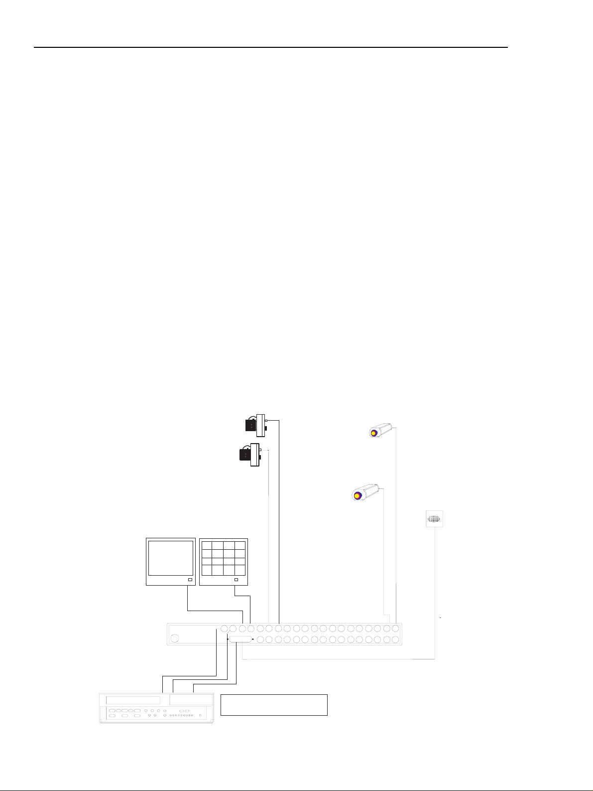
The LTC2600 Series Video Multiplexers are designed to control multichannel recording and playback with the added
capability of multiscreen viewing. The units allow monitoring of multiple camera sites without the need for multiple
monitors and VCRs. They can be programmed easily via front panel control keys and on-screen display menus.
Video multiplexers are available in the following main categories:
• Standard Models provide high quality multiplexing. They are designed to be plug-and-play, therefore simplifying
installation.
• System4 Models provide a variety of advanced system features such as control via remote keypad,PC control,
system camera control,as well as enhanced multiplexing (e.g. two multiscreen outputs and two VCRs to increase
recording speed).
• Simplex Models allow live multiscreen monitor viewing or playback or VCR recording.
• Duplex Models allow live multiscreen monitor viewing or playback and at the same time, recording all video.
Note:See Appendix A for a detailed list of features.
SECTION 1: INTRODUCTION TO THE L TC 2600 SERIES
VIDEO MULTIPLEXER
7
LTC 2600 Series Section 1 Introduction
Power
Model Mode Rated Voltage Power
No. Voltage Range
6 Channel
Standard Color Models
LTC 2622/50 Duplex 220 VAC,50/60 Hz 195.5 to 253 30 W
LTC 2622/60 Duplex 120 VAC,50/60 Hz 108 to 132 30 W
9 Channel
Standard Monochrome Models
LTC 2631/50 Simplex 230 VAC,50/60 Hz 195.5 to 253 30 W
LTC 2631/60 Simplex 120 VAC,50/60 Hz 108 to 132 30 W
LTC 2632/50 Duplex 230 VAC,50/60 Hz 195.5 to 253 30 W
LTC 2632/60 Duplex 120 VAC,50/60 Hz 108 to 132 30 W
Standard Color Models
LTC 2641/50 Simplex 230 VAC,50/60 Hz 195.5 to 253 30 W
LTC 2641/60 Simplex 120 VAC,50/60 Hz 108 to 132 30 W
LTC 2642/50 Duplex 230 VAC,50/60 Hz 195.5 to 253 30 W
LTC 2642/60 Duplex 120 VAC,50/60 Hz 108 to 132 30 W
System4 Color Models
LTC 2672/50 Duplex 230 VAC,50/60 Hz 195.5 to 253 30 W
LTC 2672/60 Duplex 120 VAC,50/60 Hz 108 to 132 30 W
16 Channel
Standard Monochrome Models
LTC 2651/50 Simplex 230 VAC,50/60 Hz 195.5 to 253 30 W
LTC 2651/60 Simplex 120 VAC,50/60 Hz 108 to 132 30 W
LTC 2652/50 Duplex 230 VAC,50/60 Hz 195.5 to 253 30 W
LTC 2652/60 Duplex 120 VAC,50/60 Hz 108 to 132 30 W
Standard Color Models
LTC 2661/50 Simplex 230 VAC,50/60 Hz 195.5 to 253 30 W
LTC 2661/60 Simplex 120 VAC,50/60 Hz 108 to 132 30 W
LTC 2662/50 Duplex 230 VAC,50/60 Hz 195.5 to 253 30 W
LTC 2662/60 Duplex 120 VAC,50/60 Hz 108 to 132 30 W
System4 Color Models
LTC 2681/50 Simplex 230 VAC,50/60 Hz 195.5 to 253 30 W
LTC 2681/60 Simplex 120 VAC,50/60 Hz 108 to 132 30 W
LTC 2682/50 Duplex 230 VAC,50/60 Hz 195.5 to 253 30 W
LTC 2682/60 Duplex 120 VAC,50/60 Hz 108 to 132 30 W
16151413121110987
654321
MON AMON B
VCR
OUT
VCR
IN
ALARM
Philips
Philips
Out
In
PIR Sensor
Video
Video
Main MonitorSpot Monitor
Video
Up to 16 cameras
Head Switching Pulse
VCR
Head Switching Pulse
Gnd
LTC 2600 Series
PIN 21 VEXT Input
Pin 25
VEXT In
Figure 1A:Typical Video Multiplexer System
8
9
LTC 2600 Series Section 2 Installation
2.1 Mounting
The multiplexer is supplied as a desktop unit. If desired the unit may be rack mounted using the included rack
mount kit.
2.2 Connecting the Video Multiplexer System
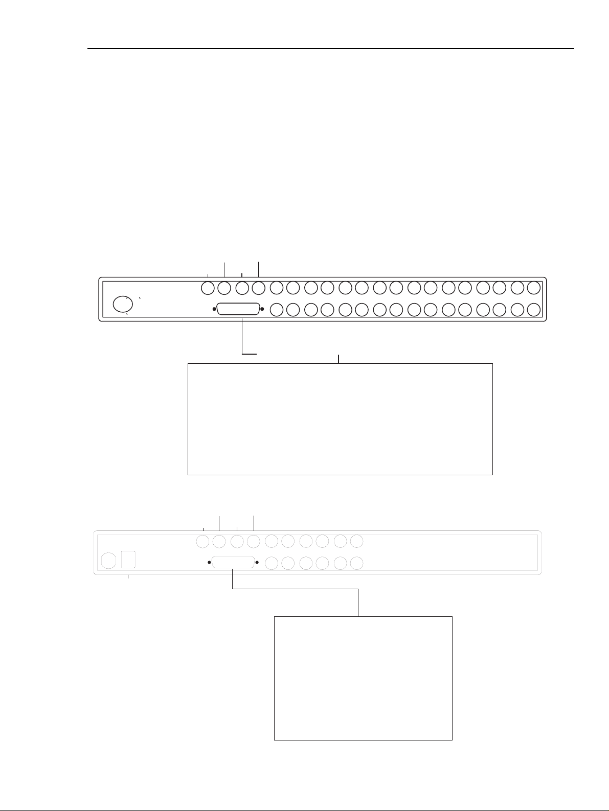
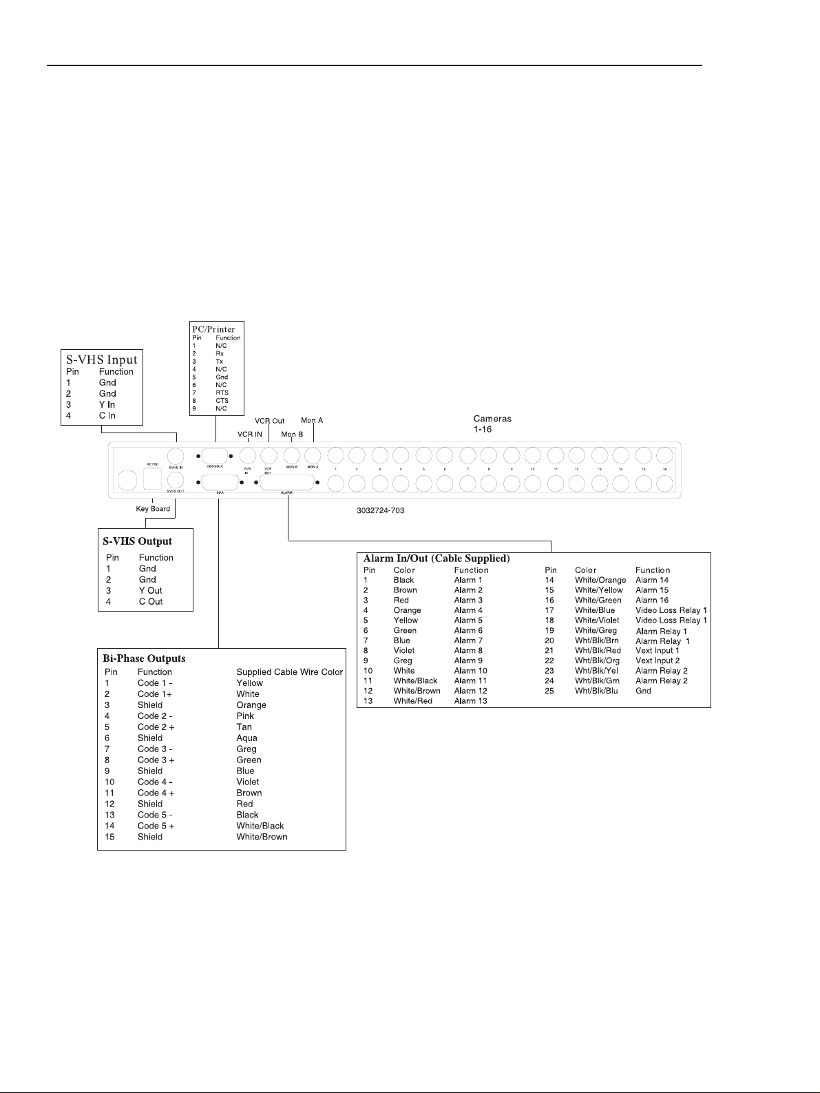
1. Refer to Figures 2A and 2B for details on the input/output connections supplied by the multiplexer.
(Be sure to reference the appropriate drawing for your multiplexer model.)
2. Review the typical installation diagrams provided in Appendix B at the back of the manual,and determine
the number of cameras,monitors,and VCRs to be incorporated into the system.
3. Connect all peripherals (e.g.cameras, monitors, VCRs) to the corresponding inputs/outputs on the multiplexer
rear panel.
SECTION 2: INST ALLING THE VIDEO MUL TIPLEXER
16151413121110987654321
MON AMON B
VCR
OUT
VCR
IN
ALARM
3032724-703
VCR IN
VCR Out
Mon B
Mon A
Cameras
1-16
Power
Alarm In/Out (Cable Supplied)
Pin Color Function Pin Color Function
1 Black Alarm 1 14 White/Orange Alarm 14
2 Brown Alarm 2 15 White/Yellow Alarm 15
3 Red Alarm 3 16 White/Green Alarm 16
4 Orange Alarm 4 17 White/Blue Video Loss Relay 1
5 Yellow Alarm 5 18 White/Violet Video Loss Relay 1
6 Green Alarm 6 19 White/Greg Alarm Relay 1
7 Blue Alarm 7 20 Wht/Blk/Brn Alarm Relay 1
8 Violet Alarm 8 21 Wht/Blk/Red Vext Input 1
9 Grey Alarm 9 22 Wht/Blk/Org N/C
10 White Alarm 10 23 Wht/Blk/Yel N/C
11 White/Black Alarm 11 24 Wht/Blk/Grn N/C
12 White/Brown Alarm 12 25 Wht/Blk/Blu Gnd
13 White/Red Alarm 13
Figure 2A:16-Channel Back Panels
Figure 2B:6-Channel Back Panels
VCR Out
VCR IN
KEYBD
Key Board
VCR
IN
M on A
M on B
VCR
OUT
ALARM/SDA
Cam eras
1-16
MON AMON B
ALARM /SDA
Pin Function
1
Alarm 1
2
Alarm 2
3
Alarm 3
4
Alarm 4
5
Alarm 5
6
Alarm 6
7
Gnd
8
Vext Input 1
9
Alarm Relay 1
10
Alarm Relay 1
Video Loss Relay 1
11
Video Loss Relay 1
12
13
C ode 1 -
654321
Pin
Function
14
C ode 1 +
15
Shield
16
C ode 2 -
17
C ode 2 +
18
Shield
19
C ode 3 -
20
C ode 3 +
21
Shield
22
C ode 4 -
23
C ode 4 +
24
Shield
Gnd
25
10
LTC 2600 Series Section 2 Installation
Figure 2C:16-Channel System4 Back Panels
*
**When using Remote Keyboard LTC 2601/00 or LTC 2602/00,
to control Philips VCRs, please use the following connections.
From Console Port of System4 to RS-232 Port of Philips VCRs
Function 9 Pin D sub to 25 Pin D sub
Rx 2 2
Gnd 5 1+7
Tx 3 3
or purchase a S1383 cable.
* S-VHS (IN/OUT)
Limited Distance Need S-VHS VCR and S-VHS Tape
11
2.3 Programming
1. When all connections have been successfully completed, apply power to the system.
2. Upon power up, the multiplexer will be using the factory-set default parameters. (See Appendix C for a
complete listing of the Factory Default Settings.)
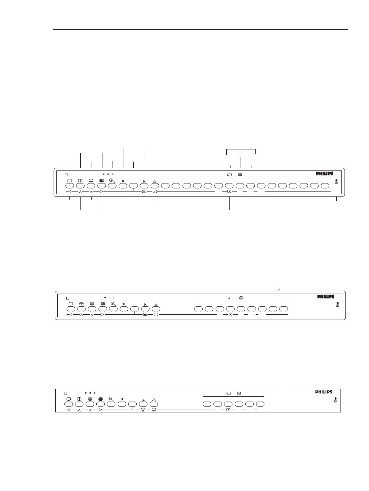
3. Refer to Figures 2D, 2E and 2F for a detailed review of the multiplexer front panel controls which will be used
in programming.Summaries of the control functions (primary and secondary) and the LED indicators are
provided in the adjacent tables.
LTC 2600 Series Section 2 Installation
Figure 2D:16-Channel Front Panel
Figure 2E:9-Channel Front Panel
Figure 2F:6-Channel Front Panel
FULL
Video Multiplexer
LEFT
Video Multiplexer
QUAD
UP
MULTI
DOWN
CAMEO
RIGHT
ZOOM
FREEZE
ALT
ACTION
CLEAR
ALARM
CLEAR
ALMACT
VCR
MENU
SELECT
ACT
ALM
123456789
VCR
LED INDICATOR
CAMEO
CAMERA
SEQ
MON B
SEQ
KEYBOARD
#
987654321
PLAY
REC
#
PLAY REC
16151413121110
POWER LED
V id e o M u lt ip le x e r
SEQ
PLAY
#
.6
REC
ACT
ALT
ALM
12345
VCR
12
LTC 2600 Series Section 2 Installation
Indicators
LED Indication
POWER Power supplied to unit
ALT Primary indication:Alternate
functions (Flashing):Camera-
to cameo mode (ALT + SELECT)
RECORD Record mode enabled
PLAYB ACK Playback mode enabled
VCR T est VCR T est enabled
MON B Monitor B enabled (Front panel keys
control monitor B display)
SEQ Sequence mode enabled
CAMEO Cameo mode enabled
(Camera keys control cameo images
CAMERA Camera mode enabled
(Camera keys control camera images)
KEYPAD Numeric mode enabled
(Camera keys act as numeric keys)
ZOOM Enlarge/zoom mode enabled
ACT Steady:Action is enabled
Flashing:Action has occurred
ALM Steady:Alarm is enabled
Flashing:Alarm has occurred.
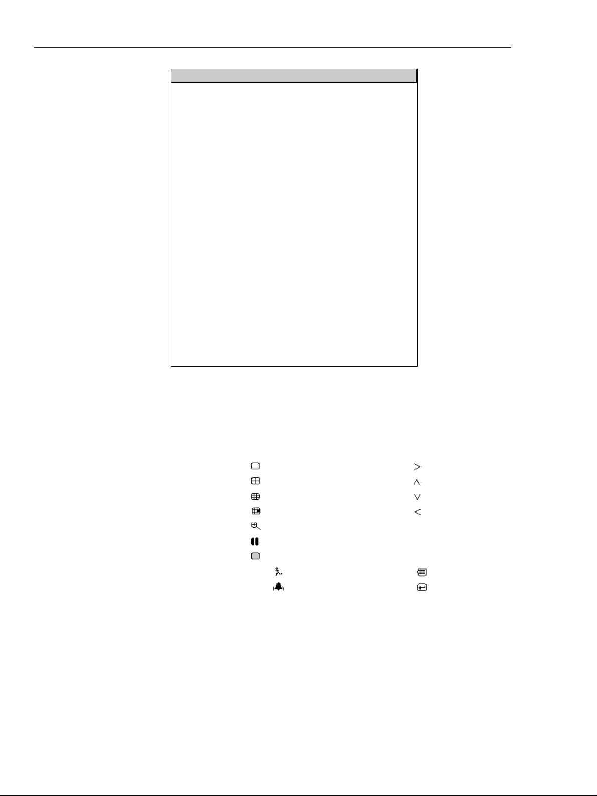
Controls
Primary Selections Secondary Selections
Description Icon Description Icon
FULL LEFT
QUAD UP
MULTI DOWN
CAMEO RIGHT
ZOOM
FREEZE
ALT
ACTION CLEAR ACT MENU
ALARM CLEAR ALM SELECT
4. The multiplexer is programmed through on-screen menus which include access to on-screen HELP information.
The menus will be displayed on Monitor A in the system.
5. To access the menu screens,press the ALT key followed by the MENU key .
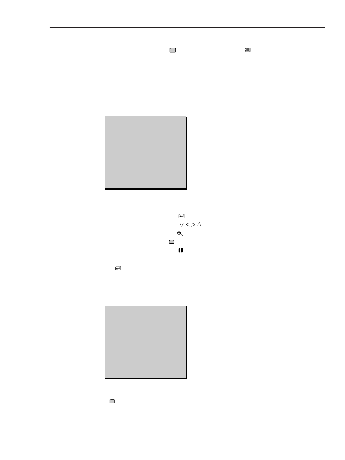
6. The Main Menu (as shown below) displays two setup options: Quick Setup and Advanced Setup.
- Quick Setup will provide all the basic programming necessary for typical systems
- Choose Advanced Setup when configuration requires such functions as alarm,motion, etc.
To perform the Advanced Setup for customized system configurations,first select Advanced Setup from the
main menu;then program the Time/Date,Autoset, and VCR setups as described in the following paragraphs; and
then refer to Section 4 for additional programming instructions.
Each menu screen includes two lines at the bottom showing the options that can be selected. These options
are:
CHOOSE Press SELECT key
MORE Use direction keys
EXIT Press ZOOM key
HELP Press AL T key
DEFAULT Press FREEZE key
ENTER CHARACTER Use direction keys to scroll through characters
When the SELECT key is pressed,all programmed settings are saved into non-volatile memory.
NOTE: A complete listing of all menu trees is provided at the back of the manual in Appendix D.
7. For typical video multiplexer system operations, select the Quick Setup option from the Main Menu.
NOTE: The Quick Setup program includes: Time/Date,AutoSet, and VCR setup.Quick Setup guides you
through all of these steps. If for any reason you need further information, consult the built-in HELP feature by
pressing the ALT key .
LTC 2600 Series Section 2 Installation
QUICK SETUP
SETUP 1
>TIME/DATE
AUTOSET
VCR SETUP
Choose:SELECT More:V
Exit:ZOOM
MAIN MENU 1.00
SETUP 1
>QUICK SETUP
ADVANCED SETUP
Choose:SELECT More:V
Exit:ZOOM
13

14
8. Select Time/Date from the Quick Setup menu. Enter the time format (12 or 24 hours), time, date format
(dd/mm/yyyy;mm/dd/yyyy;yyyy/mm/dd) and date information as requested. Use the direction (arrow) keys to
move the cursor and to scroll through parameter settings. Use the SELECT key to choose the parameter
you want to program and to save your selections. When you have finished programming all time/date
parameters,use the ZOOM key to return to the Quick Setup menu.
NOTE: The multiplexer encodes the time/date onto each field of video sent to the VCR. In the Live Display mode,
the time/date is displayed on the monitor. If the VCR's time/date display is ON,each screen in the playback mode
will also show the time/date. (You may want to switch the VCR time/date display OFF.)
9. Select AutoSet from the Quick Setup menu to automatically configure the video multiplexer for the number of
cameras connected. (A sample AutoSet menu is shown below.) Recording, sequence, and video loss list are also
configured via this menu.
10.Selecting AUT OSET ALL BELOW will automatically set the record list,sequence, and video loss list (according
to the number of camera inputs detected by the multiplexer). Selecting any of the other options in this menu
will set only the selected option.
11. When Autoset is completed, a message indicating so will be displayed for nine seconds. The camera inputs
detected in the setup process are also displayed as shown in this sample screen.
LTC 2600 Series Section 2 Installation
TIME/DATE
>TIME FORMAT 12hr
TIME 01:00:00AM
DATE FORMAT MM/DD/YYYY
DATE 01/01/1998
Choose:SELECT More:V
Edit: >< Exit:ZOOM
AUTOSET
SETUP 1
>AUT OSET ALL BELO W
RECORD LIST
VIDEO LOSS LIST
SEQUENCES
Choose:SELECT More:V
Exit:ZOOM
AUT OSET ALL
SETUP 1
01 02 03 04 05 06 -- -- --
-- -- -- -- -- -- -- -- -- -- -The above cameras were
included in selected system
list(s).
HIT ANY KEY TO CONTINUE
 Loading...