

Page 1
LTC 2372,LTC 2375
LTC 2376,LTC 2377
VidQuadDigital Processor Units
Installation Instructions
Eng
F
D
E
NL
I
Page 2

IMPORTANT SAFEGUARDS
1. Read Instructions - All the safety and operating instructions should be read
before the unit is operated.
2. Retain Instructions - The safety and operating instructions should be
retained for future reference.
3. Heed Warnings - All warnings on the unit and in the operating
instructions should be adhered to.
4. Follow Instructions - All operating and use instructions should be followed.
5. Cleaning - Unplug the unit from the outlet before cleaning. Do not use
liquid cleaners or aerosol cleaners. Use a damp cloth for cleaning.
6. Attachments - Do not use attachments not recommended by the product
manufacturer as they may cause hazards.
7. Water and Moisture - Do not use this unit near water - for example, near a
bath tub, wash bowl, kitchen sink, or laundry tub, in a wet basement, near
a swimming pool, in an unprotected outdoor installation, or any area
which is classified as a wet location.
8. Accessories - Do not place this unit on an unstable stand, tripod, bracket,
or mount. The unit may fall, causing serious injury to a person and serious
damage to the unit. Use only with a stand, tripod, bracket, or mount
recommended by the manufacturer, or sold with the product. Any
mounting of the unit should follow the manufacturer's instructions, and
should use a mounting accessory recommended by the manufacturer.
An appliance and cart combination should be moved with care.
Quick stops, excessive force, and uneven surfaces may cause the
appliance and cart combination to overturn.
9. Ventilation - Openings in the enclosure, if any, are provided for ventilation
and to ensure reliable operation of the unit and to protect it from
overheating. These openings must not be blocked or covered. This unit
should not be placed in a built-in installation unless proper ventilation is
provided or the manufacturer's instructions have been adhered to.
10. Power Sources - This unit should be operated only from the type of power
source indicated on the marking label. If you are not sure of the type of
power supply you plan to use, consult your appliance dealer or local power
company. For units intended to operate from battery power, or other
sources, refer to the operating instructions.
11. Grounding or Polarization - This unit may be equipped with a polarized
alternating-current line plug (a plug having one blade wider than the
other). This plug will fit into the power outlet only one way. This is a
safety feature. If you are unable to insert the plug fully into the outlet, try
reversing the plug. If the plug should still fail to fit, contact your electrician
to replace your obsolete outlet. Do not defeat the safety purpose of the
polarized plug.
Alternately, this unit may be equipped with a 3-wire grounding-type plug,
a plug having a third (grounding) pin. This plug will only fit into a
grounding-type power outlet. This is a safety feature. If you are unable to
insert the plug into the outlet, contact your electrician to replace your
obsolete outlet. Do not defeat the safety purpose of the grounding-type
plug.
12. Power-Cord Protection - Power-supply cords should be routed so that they
are not likely to be walked on or pinched by items placed upon or against
them, paying particular attention to cords and plugs, convenience
receptacles, and the point where they exit from the appliance.
13. Power Lines - An outdoor system should not be located in the vicinity of
overhead power lines or other electric light or power circuits, or where it
can fall into such power lines or circuits. When installing an outdoor
system, extreme care should be taken to keep from touching such power
lines or circuits as contact with them might be fatal. U.S.A. models only refer to the National Electrical Code Article 820 regarding installation of
CATV systems.
14. Overloading - Do not overload outlets and extension cords as this can
result in a risk of fire or electric shock.
15. Object and Liquid Entry - Never push objects of any kind into this unit
through openings as they may touch dangerous voltage points or short-out
parts that could result in a fire or electric shock. Never spill liquid of any
kind on the unit.
16. Servicing - Do not attempt to service this unit yourself as opening or
removing covers may expose you to dangerous voltage or other hazards.
Refer all servicing to qualified service personnel.
17. Damage Requiring Service - Unplug the unit from the outlet and refer
servicing to qualified service personnel under the following conditions:
a. When the power-supply cord or plug is damaged.
b. If liquid has been spilled, or objects have fallen into the unit.
c. If the unit has been exposed to rain or water.
d. If the unit does not operate normally by following the operating
instructions. Adjust only those controls that are covered by the
operating instructions, as an improper adjustment of other controls
may result in damage and will often require extensive work by a
qualified technician to restore the unit to its normal operation.
e. If the unit has been dropped or the cabinet has been damaged.
f. When the unit exhibits a distinct change in performance--this
indicates a need for service.
18. Replacement Parts - When replacement parts are required, be sure the
service technician has used replacement parts specified by the manufacturer
or have the same characteristics as the original part. Unauthorized
substitutions may result in fire, electric shock or other hazards.
19. Safety Check - Upon completion of any service or repairs to this unit, ask
the service technician to perform safety checks to determine that the unit is
in proper operating condition.
20. Coax Grounding - If an outside cable system is connected to the unit, be
sure the cable system is grounded. U.S.A. models only--Section 810 of the
National Electrical Code, ANSI/NFPA
No.70-1981, provides information with respect to proper grounding of the
mount and supporting structure, grounding of the coax to a discharge unit,
size of grounding conductors, location of discharge unit, connection to
grounding electrodes, and requirements for the grounding electrode.
21. Lightning - For added protection of this unit during a lightning storm, or
when it is left unattended and unused for long periods of time, unplug it
from the wall outlet and disconnect the cable system. This will prevent
damage to the unit due to lightning and power-line surges.
FCC & ICES INFORMATION
(U.S.A. AND CANADIAN MODELS ONLY)
WARNING - This equipment has been tested and found to comply with the
limits for a Class A digital device, pursuant to Part 15 of the FCC Rules and
ICES-003 of Industry Canada. These limits are designed to provide reasonable
protection against harmful interference when the equipment is operated in a
residential installation. This equipment generates, uses and can radiate radio
frequency energy and, if not installed and used in accordance with the
instructions, may cause harmful interference to radio communications.
Operation of this equipment in a residential area is likely to cause harmful
interference in which case the user will be required to correct the interference at
his own expense. Intensional or unintensional changes or modifications not
expressly approved by the party responsible for compliance shall not be made.
Any such changes or modifications could void the user’s authority to operate
the equipment.
If necessary, the user should consult the dealer or an experienced
radio/television technician for corrective action. The user may find the
following booklet prepared by the Federal Communications Commission
helpful: "How to Identify and Resolve Radio-TV Interference Problems". This
booklet is available from the U.S. Government Printing Office, Washington,
DC 20402, Stock No.004-000-00345-4.
1.2
Warning
This is a class A product. In a domestic environment this
product may cause radio interference in which case the user
may be required to take adequate measures.
Page 3
1.3
SAFETY PRECAUTIONS
This label may appear on the bottom of the unit due to space
limitations.
The lightning flash with an arrowhead symbol, within an
equilateral triangle, is intended to alert the user to the
presence of un-insulated "dangerous voltage" within the
product's enclosure that may be of sufficient magnitude to
constitute a risk of electric shock to persons.
The exclamation point within an equilateral triangle is
intended to alert the user to presence of important
operating and maintenance (servicing) instructions in the
literature accompanying the appliance.
Attention: Installation should be performed by qualified
service personnel only in accordance with the National
Electrical Code or applicable local codes.
Power Disconnect. Units with or without ON-OFF
switches have power supplied to the unit whenever the
power cord is inserted into the power source; however, the
unit is operational only when the ON-OFF switch is in the
ON position. The power cord is the main power
disconnect for all units.
CONTENTS
1 UNPACKING . . . . . . . . . . . . . . . . . . . . . . . . . . .1.3
1.1 VidQuad Digital Processor Unit . . . . . . . . . . . . . . .1.3
2 SERVICE . . . . . . . . . . . . . . . . . . . . . . . . . . . . . . .1.3
3 DESCRIPTION . . . . . . . . . . . . . . . . . . . . . . . . . .1.3
3.1 LTC 2372 & LTC 2375 . . . . . . . . . . . . . . . . . . . .1.3
3.2 LTC 2376 & LTC 2377 . . . . . . . . . . . . . . . . . . . .1.3
4 INSTALLATION . . . . . . . . . . . . . . . . . . . . . . . . .1.5
4.1 LTC 2372 & LTC 2375 . . . . . . . . . . . . . . . . . . . .1.5
4.2 LTC 2376 & LTC 2377 . . . . . . . . . . . . . . . . . . . .1.5
5 PROGRAMMING . . . . . . . . . . . . . . . . . . . . . . . .1.7
5.1 LTC 2372 & LTC 2375 . . . . . . . . . . . . . . . . . . . .1.7
5.2 LTC 2376 & LTC 2377 . . . . . . . . . . . . . . . . . . . .1.7
5.3 Time and Date . . . . . . . . . . . . . . . . . . . . . . . . . . . .1.8
5.4 Camera Sequence Setup . . . . . . . . . . . . . . . . . . . . .1.8
5.5 Alarm Setup . . . . . . . . . . . . . . . . . . . . . . . . . . . . . .1.9
5.6 VCR Out Mode . . . . . . . . . . . . . . . . . . . . . . . . . .1.10
5.7 Camera Titles . . . . . . . . . . . . . . . . . . . . . . . . . . . .1.10
5.8 Color Adjustment . . . . . . . . . . . . . . . . . . . . . . . . .1.11
5.9 Set the Password . . . . . . . . . . . . . . . . . . . . . . . . . .1.12
6 OPERATION . . . . . . . . . . . . . . . . . . . . . . . . . . .1.13
6.1 LTC 2372 and LTC 2375 Operation . . . . . . . . . .1.13
6.2 LTC 2376 and LTC 2377 Operation . . . . . . . . . .1.13
7 MAINTENANCE . . . . . . . . . . . . . . . . . . . . . . .1.15
1 UNPACKING
Unpack carefully. This is electronic equipment and should be
handled carefully.
Check to ensure that the following items are included for the
applicable modules ordered:
n LTC 237x VidQuad
Digital Processor Unit.
n Accessory pack.
n Installation Instructions.
If the item appears to have been damaged in shipment, replace
it properly in its carton and notify the shipper. If any items are
missing, notify your Philips Communication & Security
Systems Sales Representative or Customer Service.
The shipping carton is the safest container in which the unit
may be transported. Save it for possible future use.
1.1 VidQuad Digital Processor Units
The LTC 237x VidQuad Digital Processor Units provide onscreen display of four camera inputs combined with numerous
additional functions. The image display is updated depending
on the model, providing either near or genuine real-time video.
The models available are:
Model Rated Voltage Power at System
No. Voltage Range Rated
Voltage
Monochrome Models
LTC 2372/60 120 VAC, 60 Hz 108 to 132 6 W EIA
LTC 2372/50 230 VAC, 50 Hz 195.5 to 253 6 W CCIR
LTC 2376/60 120 VAC, 60 Hz 108 to 132 6 W EIA
LTC 2376/50 230 VAC, 50 Hz 195.5 to 253 6 W CCIR
Color Models
LTC 2375/60 120 VAC, 60 Hz 108 to 132 12 W NTSC
LTC 2375/50 230 VAC, 50 Hz 195.5 to 253 12 W PAL
LTC 2377/60 120 VAC, 60 Hz 108 to 132 12 W NTSC
LTC 2377/50 230 VAC, 50 Hz 195.5 to 253 12 W PAL
2 SERVICE
If the unit ever needs repair service, the customer should contact
the nearest Philips Communication & Security Systems Service
Center for authorization to return and shipping instructions.
3 DESCRIPTION
3.1 LTC 2372 & LTC 2375
The LTC 2372 VidQuadDigital Monochrome Processor and
the LTC 2375 VidQuadDigital Color Processor provide four
camera inputs. The units display high quality pictures from four
cameras at one time on a monitor screen. The image display is
updated at the field rate of 30 fields/sec. (NTSC), 25 fields/sec.
(PAL), providing near-real-time video.
3.2 LTC 2376 & LTC 2377
The LTC 2376 VidQuadDigital Monochrome Processor and
the LTC 2377 VidQuadDigital Color Processor provide onscreen display of four camera inputs combined with numerous
additional functions. Each quadrant may be sequenced full
screen in place of being displayed in a quad split. The image
display is updated at the field rate of 60 fields/sec. (NTSC), 50
fields/sec. (PAL), providing genuine real-time video. In addition
to the quad screen display, the units offer VCR "ZOOM"
CAUTION: TO REDUCE THE RISK OF ELECTRICAL
SHOCK, DO NOT OPEN COVERS. NO USER
SERVICEABLE PARTS INSIDE. REFER SERVICING TO
QUALIFIED SERVICE PERSONNEL.
WARNING
TO PREVENT FIRE OR SHOCK HAZARD, DO NOT
EXPOSE UNITS NOT SPECIFICALLY DESIGNED FOR
OUTDOOR USE TO RAIN OR MOISTURE.
Page 4
1.4
playback function to allow full screen viewing during tape
playback.
Note: To eliminate vertical roll during sequencing, (Quad to
camera 1 only) the VidQuad output synchronizes to input 1. For
the LTC 2377 series, it is recommended to have a color camera as
camera 1.
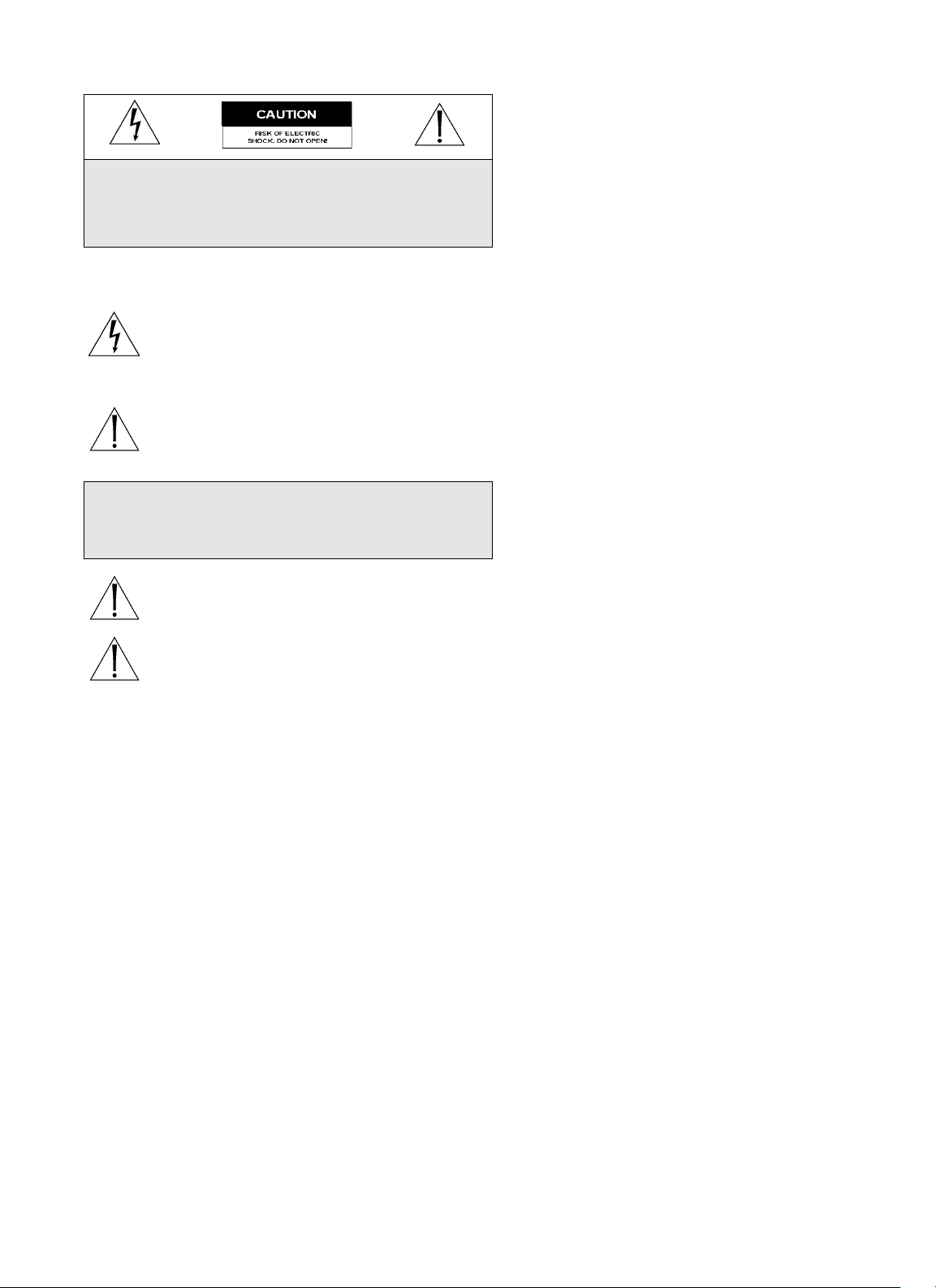
Fig. 1: Typical Configuration for LTC 2372 and LTC 2375 VidQuad Digital Processor Unit
Fig. 2: Configuration for LTC 2376 and LTC 2377 VidQuad Digital Processor Unit using VCR only
Power
1
MON
GND
2
4
3
Camera 4
Camera 3
Camera 2
Camera 1
PHILIPS
Camera 1
18
Camera 2
Camera 3
Camera 4
15
ALARM OUT
ALARM IN
REMOTE
GND
COM 1 2 3 4
NCCOMNO G S
RELAY TRIG
9
12
3
MON
4
IN
1
VCR
OUT
2
4
3
Power
Looping (Automatic Termination)
Alarm
Contact
IN OUT
VCR
Page 5

1.5
4 INSTALLATION
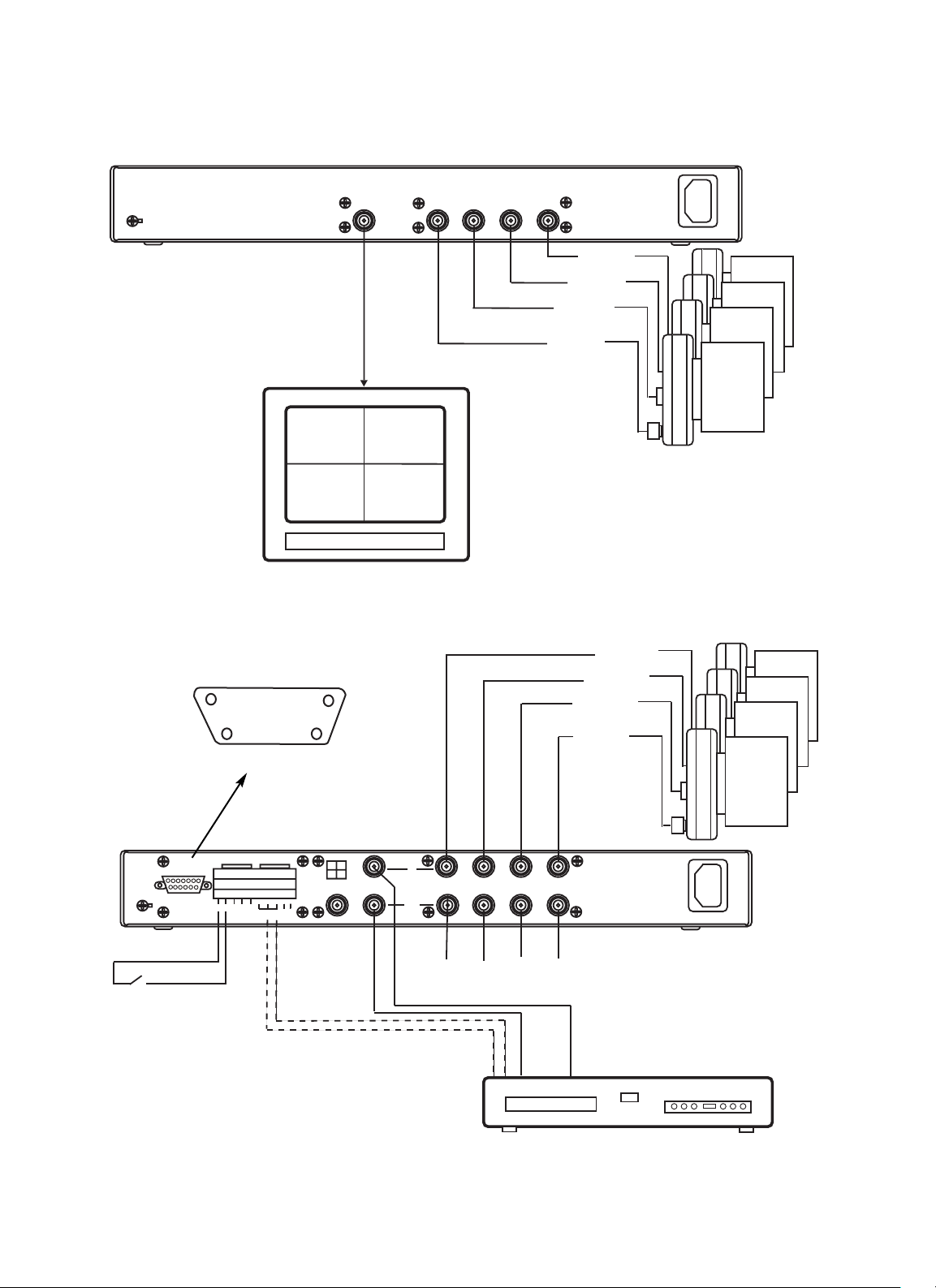
4.1 LTC 2372 and LTC 2375 Connection
Fig. 4: LTC 2372 and LTC 2375 connection
Fig. 3: Configuration for LTC 2376 and LTC 2377 VidQuad Digital Processor Unit with Monitor Option
Camera 1
Quad display only
Item VidQuad Digital Processor
Camera 1 Video Input 1 - BNC
Camera 2 Video Input 2 - BNC
Camera 3 Video Input 3 - BNC
Camera 4 Video Input 4 - BNC
Monitor Video Mon - BNC
Camera 2
18
Camera 3
Camera 4
GND
Alarm
Contact
PHILIPS
15
REMOTE
ALARM IN
COM 1 2 3 4
9
ALARM OUT
NCCOMNO G S
RELAY TRIG
12
3
4
MON
PHILIPS
IN
1
VCR
OUT
2
4
3
Power
Looping (Automatic Termination)
IN OUT
VCR
Main Monitor
Monitor
GND
MON
1
2
4
3
Page 6

1.6
4.2 LTC 2376 and LTC 2377 Connection
Notes:
1. The LTC 2377 provides a COLOR Adjustment menu to
assist initial monitor adjustment.
2. If the video line ends at the system monitor, set the
monitor's termination switch to 75 OHMS. If the video is
looped through the monitor to some other item of
equipment, set the monitor termination switch to HIGH Z
or HIGH IMPEDANCE. The last video in the line must be
terminated with 75 ohms.
3. If the video is to be looped out to other equipment, make
sure that the final item of video equipment on each line is
terminated with 75 ohms.
4. The VCR can be connected to the unit to allow it to
respond to alarms.
5. Do not apply any voltage to any alarm input. It will damage
the unit.
6. Set the host computer to the half-duplex mode.
The LTC2376 and LTC 2377 does not echo received
characters.
Fig. 5: LTC 2376 and LTC 2377 connection
Item VidQuad Digital Processor
Video Inputs
Camera 1 Video Input 1 - BNC
Camera 2 Video Input 2 - BNC
Camera 3 Video Input 3 - BNC
Camera 4 Video Input 4 - BNC
Video Outputs
Main Monitor Video MON - BNC
(1)
Quad Monitor Video VCR OUT - BNC
(2)
Loop-through 1 Video Output 1 - BNC
(3)
Loop-through 2 Video Output 2 - BNC
(3)
Loop-through 3 Video Output 3 - BNC
(3)
Loop-through 4 Video Output 4 - BNC
(3)
VCR Out VCR IN - BNC
VCR In VCR OUT - BNC
(4)
Alarm In
Alarm 1 ALARM IN Pin 1
(5)
Alarm 2 ALARM IN Pin 2
(5)
Alarm 3 ALARM IN Pin 3
(5)
Alarm 4 ALARM IN Pin 4
(5)
Common ALARM COM
Alarm inputs are Class 2 input only.
Alarm input cables must be shielded, and the shield must
be grounded.
Item VidQuad Digital Processor
Alarm Out
VCR Alarm RELAY NO (or NC)
RELAY COM
Trigger Out TTL OUTPUT
Remote
Pin Function
1 VCR
2 Menu
3 SEQ/
4 Camera 1/Menu scroll key
5 Camera 2/Menu scroll key
6 Camera 3/Menu scroll key
7 Camera 4/Menu scroll key
8/
9 Received
10-15 GND
RS-232 protocol
(6)
Data rate 1200 baud
Data bits 8
Parity None
Stop bits 1
>
<
>
ALARM OUT
ALARM IN
GND
REMOTE
COM 1 2 3 4
NCCOMNO G S
RELAY TRIG
12
3
MON
4
IN
1
VCR
OUT
2
4
3
ALM ( )
>
Page 7

1.7
5. PROGRAMMING
5.1 LTC 2372 & LTC 2375
No programming required.
5.2 LTC 2376 & LTC 2377
Programming the LTC 2376 and LTC 2377 includes writing
titles for the video inputs, assigning dwell times to each input
and to the quad display for sequencing (SEQ) operating,
enabling or disabling the video loss alarm, and enabling or
disabling the security lock. Each of these functions comes
preprogrammed with a factory default setting.
n Press the MENU key to display the programming screen.
For the LTC 2376/2377 the following screen is displayed:
* LTC 2377 only.
All programming is done with the front panel keys. There
are eight keys on the front panel. The keys named MENU,
1/ , 2/ , 3/ , 4/ , and / are used in
programming the unit.
The VCR and SEQ/ keys are not used in
programming the unit. Functions of each key on the front
panel are described in the table above.
Table (Key Functions)
Key label Operating Function Programming Function
VCR Selects VCR input for display on monitor NONE
Menu NONE Enter the programming mode
Seq/ Selects the sequential switching function NONE
1/ Selects camera 1 for full-screen display on monitor Scrolls upward through program selections ; selects
entries
2/ Selects camera 2 for full-screen display on monitor Scrolls downward through program selections; selects
entries
3/ Selects camera 3 for full-screen display on monitor Shifts cursor to the left in menus; selects entries
4/ Selects camera 4 for full-screen display on monitor Shifts cursor to the right in menus; selects entries
/ Selects quad display on monitor Enter or set function
Fig. 6 LTC 2372 and LTC 2375 Front panel
Fig. 7 LTC 2376 and LTC 2377 Front panel
(1) TIME/DATE
(2) SEQ SETUP
(3) ALARM SETUP
(4) VCR OUT MODE
(5) CAMERA TITLES
(6) COLOR ADJUST*
(7) PASSWORD SET
(8) EXIT
VidQuad
PHILIPS
VidQuad
VCR
MODE
Menu
Seq
( )
ALM
DISPLAY
3
2
1
4
PHILIPS
ALM ( )
>
>
<
>
>
>
>
<
ALM ( )
Page 8

1.8
5.3 Time and Date
This menu allows you to set the date and time format, the
current time/date and displayed position on the monitor.
n Select TIME/DATE and press the key. The following
menu is displayed:
5.3.1 Time Format
n Select TIME FORMAT and press the key. The
following menu is displayed:
n Press the 1 key, and toggle to select the required format.
Options are:
12 HOURS (AM/PM)
24 HOURS (0000-2359).
n Press the key.
5.3.2 Date Format
n Select DATE FORMAT and press the key. The
following menu is displayed:
n Press the 1 key, and toggle to select the required format.
Options are:
MM/DD/YEAR
DD/MM/YEAR
YEAR/MM/DD
n Press the key.
5.3.3 Time/Date Set
n Select TIME/DATE SET and press the key. The
following menu is displayed:
n Press the and keys to move the cursor to the
required position.
n Press the and keys to establish the necessary digit.
(Calenders until the year of 2097 are in this menu.)
n Press the key.
5.3.4 Display Mode Set
n Select the DISPLAY function.
n Press the key to toggle through BOTTOM, TOP, and
OFF. The Date/Time will be displayed on the monitor in
the selected position.
n Select EXIT and press the key to exit the menu.
5.4 Camera Sequence Setup
This menu allows you to adjust the dwell times of the 4 camera
video and the Quad screens.
n Select SEQ SETUP and press the key. The following
menu is displayed:
n Press the and keys to move the cursor to required
channel.
(1) TIME FORMAT
(2) DATE FORMAT
(3) TIME/DATE SET
(4) DISPLAY : BOTTOM
(5) EXIT
TIME FORMAT
12 HOURS (AM/PM)
DATE FORMAT
MM/DD/YEAR
TIME/DATE SET
_
12:00:00 AM 12/31/1999
HH:MM:SS MM/DD/YEAR
TO EXIT PRESS ENTER KEY
(1) TIME FORMAT
(2) DATE FORMAT
(3) TIME/DATE SET
(4) DISPLAY : BOTTOM
(5) EXIT
DWELL TIME
(1) CAMERA 1 : 9 SEC
(2) CAMERA 2 : 9 SEC
(3) CAMERA 3 : SKIP
(4) CAMERA 4 : 9 SEC
(5) QUAD : 9 SEC
(6) EXIT
><
>
>
>
>
Page 9

1.9
n Press the key to increase the dwell time. Dwell times
may be programmed from SKIP to 9 seconds. (When you
reach 9 seconds, pressing the key will toggle you
through the sequence again. A setting of "SKIP" removes
the channel from the sequence.
n Select EXIT and press the key to exit the menu.
5.5 Alarm Setup
The ALARM SETUP menu allows you to set the alarm options
for each of the video inputs. The alarms can be set on or off,
dwell time, polarity and video loss. The unit can also have the
audio beeper set to on or off.
n Select ALARM SETUP and press the key. The
following menu is displayed:
5.5.1 Setup an Alarm Channel
You can switch the alarm function ON/OFF for each of the
four video input channels.
n Select ALARM ON/OFF and press the key. The
following menu is displayed:
n Press the and keys to move the cursor to required
channel.
n Press the key to toggle the channel ON or OFF.
n Select EXIT and press the key to exit the menu.
5.5.2 Alarm Dwell Time
The ALARM DWELL function allows you to set the automatic
reset period after an alarm is generated.
n Select ALARM DWELL and press the key. The
following menu is displayed:
n Press the and keys to adjust the time. Options are:
1-60 SEC: automatic reset period.
HOLD: alarm continues until the alarm camera key is
pressed followed by the key.
FOLLOW: alarm continues until the alarm camera key is
pressed followed by the key.
n Press the key to exit the menu.
5.5.3 Alarm Polarity
The ALARM POLARITY function enables you to define how
the alarm is generated for each alarm input, either normally
open (NO) or normally closed (NC) contacts.
n Select ALARM POLARITY and press the key. The
following menu is displayed:
n Press the and keys to move the cursor to required
channel.
n Press the key to toggle the channel NO or NC.
n Select EXIT and press the key to exit the menu.
Note:
Alarm functions are disabled when in the menu or VCR mode.
ALARM SETUP
(1) ALARM ON/OFF
(2) ALARM DWELL
(3) ALARM POLARITY
(4) VIDEO LOSS ALERT
(5) BEEPER ON
(6) EXIT
ALARM ON/OFF
(1) CHANNEL 1: ON
(2) CHANNEL 2: ON
(3) CHANNEL 3: OFF
(4) CHANNEL 4: ON
(5) EXIT
AUTO RESET TIME
60 SEC
ALARM POLARITY
(1) CHANNEL 1: NO
(2) CHANNEL 2: NO
(3) CHANNEL 3: NO
(4) CHANNEL 4: NO
(5) EXIT
>
>
ALM ( )
ALM ( )
>
>
>
>
Page 10

1.10
5.5.4 Video Loss Alert
The VIDEO LOSS ALERT function enables you to define if an
alarm is generated when any of the video inputs is lost/defective.
n Select VIDEO LOSS ALERT and press the key. The
following menu is displayed:
n Press the and keys to move the cursor to required
channel.
n Press the key to toggle the channel ON or OFF.
n Select EXIT and press the key to exit the menu.
5.5.5 Beeper On/Off
The unit incorporates a beeper to alert the operator when an
alarm is generated. You can define if the beeper is on or off.
n Select BEEPER.
n Press the key to toggle the function ON or OFF.
n Select EXIT and press the key to exit the menu.
5.6 VCR Out Mode
The VCR OUT MODE defines how the unit video output to
the VCR is recorded, either as quad mode, or as the selected
monitor output.
n Select VCR OUT MODE and press the key. The
following menu is displayed:
n Press the and keys to toggle the mode for:
DISPLAY QUAD ONLY: the output to the VCR will be
quad mode in all conditions.
SAME AS MONITOR OUT: the VCR output will be the
same as the selected monitor output.
n Press the key to exit the menu.
5.7 Camera Titles
You can set up camera titles for each camera input for display
on the monitor. A character set is available for programming
camera titles. These are:
[0][1][2][3][4][5][6][7][8][9]
[A][B][C][D][E][F][G][H][I][J][K][L][M][N][O][P][Q][R][S]
[T][U][V][W][X][Y][Z]
[.][,]['][:][+][-][?][/][(][)][?][blank space]
n Select CAMERA TITLES and press the key. The
following menu is displayed:
n Press the and keys to move the cursor to required
channel.
n Press the key to display the CAMERA TITLE SET
menu.
VIDEO LOSS ALERT
(1) CHANNEL 1: ON
(2) CHANNEL 2: ON
(3) CHANNEL 3: OFF
(4) CHANNEL 4: ON
(5) EXIT
ALARM SETUP
(1) ALARM ON/OFF
(2) ALARM DWELL
(3) ALARM POLARITY
(4) VIDEO LOSS ALERT
(5) BEEPER ON
(6) EXIT
VCR OUT MODE
DISPLAY QUAD ONLY
TO EXIT PRESS ENTER KEY
CAMERA TITLES
(1) CAMERA 1
(2) CAMERA 1
(3) CAMERA 1
(4) CAMERA 1
(5) DISPLAY: ON
(6) EXIT
>
>
>
>
>
>
Page 11

1.11
n Press the and keys to move the cursor to the
required position.
n Press the and keys to select the required character.
n Press the key to return to the CAMERA TITLES menu.
n Select EXIT and press the key to exit the menu.
5.7.1 Display ON/OFF
You can define if the camera tiles are displayed on the monitor.
n Select DISPLAY.
n Press the key to toggle either ON or OFF.
n Select EXIT and press the key to exit the menu.
5.8 Color Adjustment (LTC 2377 Only)
On the LTC 2377 Digital Color Quad Splitter Unit, you can
adjust the color brightness, contrast and chroma for each
individual camera input for optimum display.
Key code used for adjusting are:
n Changes option.
n Increase.
n Decrease.
n Advance camera #.
n Select COLOR ADJUST and press the key. The
following menu is displayed:
n Press the and keys to adjust the brightness to display
the optimum image.
n Press the key to display the next menu:
n Press the and keys to adjust the contrast to display
the optimum image.
n Press the key to display the next menu:
n Press the and keys to adjust the chroma to display
the optimum image.
n Press the key to display the next menu:
n Continue to adjust the color for each camera in turn in the
same manner.
n When all cameras have been adjusted, press the key to
exit the menu.
>
>
>
CAMERA 1 TITLE SET
CAMERA 1
TO EXIT PRESS ENTER KEY
CAMERA TITLES
(1) CAMERA 1
(2) CAMERA 1
(3) CAMERA 1
(4) CAMERA 1
(5) DISPLAY: ON
(6) EXIT
CAMERA 1 BRIGHTNESS
.............
CAMERA 1 CONTRAST
.............
CAMERA 1 CHROMA
.............
CAMERA 2 BRIGHTNESS
.............
>
<
><
>
>
>
<
>
<
>
>
<
>
Page 12

1.12
5.9 Set the Password
The unit incorporates a password function for entry to the
menu operation. This ensures that only authorized persons can
change the unit settings.
n Select PASSWORD SET and press the key. The
following menu is displayed:
n Press the and keys to move the cursor to (1) NEW
PASSWORD.
n Press the key to display the PASSWORD SETTING
menu.
n Enter your 4 digit password by pressing the 1, 2, 3 or 4
keys. When entered, the display changes to:
n Confirm your 4 digit password.
n Press the key to exit the menu.
n Select Exit to exit the main menu.
n Attempt to access the Menu by pressing “Menu”.
n Enter your 4 digit password. When a correct password is
entered, the main menu is displayed. If incorrect, the
message “Wrong Password” is displayed for 3 seconds, and
will then display the camera images.
5.9.1 Disable Password
The password function can be disabled.
n Select DISABLE PASSWORD and press the key. The
screen displays the message “Clear Password”.
n Select EXIT and press the key to exit the menu.
n Select EXIT to exit the main menu.
PASSWORD SETTING
(1) NEW PASSWORD
(2) DISABLE PASSWORD
(3) EXIT
ENTER PASSWORD
****
CONFIRM PASSWORD
****
PASSWORD SETTING
DISABLE PASSWORD
>
>
Page 13

1.13
6. OPERATION
6.1 LTC 2372 and LTC 2375 Operation
The LTC 2372 and LTC 2375 are operational as soon as power
is connected. No further action is required.
6.2 LTC 2376 and LTC 2377 Operation
Normal operating selections are made using the eight front
panel keys, and functions are selected with a single key press.
The LTC 2376 and LTC 2377 may also be controlled remotely
by a user-provided dry contact control or by a host computer
using a simple RS-232 command set.
6.2.1 Basic Operation
The basic operation includes selecting the sequence, follow,
VCR, or quad modes and selecting individual camera channels
for hold viewing. When the unit is in the operational mode
(that is, not in the programming mode), six keys (SEQ, 1, 2, 3,
4, ) perform the functions. The four keys labeled 1, 2, 3,
and 4 select video channels 1 through 4, respectively, and the
key selects the quad display.
6.2.2 VCR
The VCR key selects the input from the VCR to be displayed
on the system monitor.
You can view the recorded VCR images in a quad format or any
quad can be zoomed to full screen.
To view recorded VCR images:
1. Insert a recoded tape in the VCR and press the PLAY key.
2. Press the VCR key on the Quad unit to display the playback
video from the VCR. The LED above the VCR key remains
illuminated as long as this function is selected.
3. The VCR images can be viewed as recorded in a quad
format or any quad can be zoomed to full screen.
1 Press the "1" key: The upper left hand quad is zoomed
to full screen.
2 Press the "2" key: The upper right hand quad is zoomed
to full screen.
3 Press the "3" key: The lower left hand quad is zoomed to
full screen.
4 Press the "4" key: The lower right hand quad is zoomed
to full screen.
5 Press " " key: Display VCR video as recorded.
If the monitor screen does not display a picture when the VCR
key is pressed, check to make sure that the VCR is plugged in
and turned on, that a recorded tape is inserted, and that the
VCR is in the PLAY mode.
6.2.3 Sequence Switching
The SEQ key selects the sequential switching function. The
sequencing list and dwell times can be customized (refer to the
Programming section).
n Press the SEQ key to start video sequencing. The camera are
displayed in the order 1-2-3-4-QUAD-1-2-etc. The quad
screen is displayed after camera 4. Each camera remains on
screen for programmed dwell period, unless its dwell was set
at "SKIP". In this case, it is deleted from sequencing stack.
If the Quad unit is running in the VCR mode, pressing the
VCR key again switches the unit to the sequential switching
mode. If the Quad unit is running in the programming mode,
using by the EXIT key switches the unit to the sequential
switching mode.
LTC 2372 and LTC 2375 Front Panel
LTC 2376 and LTC 2377 Front Panel
VidQuad
VidQuad
VCR
MODE
Menu
Seq
( )
ALM
2
1
PHILIPS
DISPLAY
3
4
PHILIPS
Page 14

1.14
6.2.4 Manual Switching
n Press the 1, 2, 3, or 4 key to select manual switching. The
selected quadrants will be displayed in full screen mode.
The camera title of the selected quadrant is displayed in the
center of the monitor screen.
If the Quad unit is operating in the VCR or programming
mode, you can not use manual switch mode.
6.2.5 Quad Display
n Press the QUAD key to display all four camera inputs on
the system monitor screen. Each quadrant displays the video
from its respective camera. The four quadrants are separated
by a black border.
1 The titles of the camera 1 is displayed in the bottom
right corner of the screen.
2 The titles of the camera 2 is displayed in the bottom left
corner of the screen.
3 The titles of the camera 3 is displayed in the upper right
corner of the screen.
4 The titles of the camera 4 is displayed in the upper left
corner of the screen.
6.2.6 Alarm Function
When an alarm input is generated, the relevant camera image
appears as a full screen image and the message "*ALARM*"
flashes on screen.
For a generated alarm the sequence of operation is:
1 MON output and VCR output are changed to display
the full screen image of alarmed channel.
2 The message "*ALARM*" flashes on the screen.
3 If a second alarm input is generated, each alarm screen
appears for 2 second in turn. You can hold the required
alarmed image by pressing one of the alarming channel
keys (1~4). To disable the holding alarmed channel,
press the alarming channel key again.
4 The alarm audible beeper is activated, (If BEEPER status
is "ON").
5 The alarm output (Relay Output, Trig Output) is
activated automatically.
To reset the activated alarm:
n Press the Camera (1, 2, 3, or 4) key, then the key.
The duration of the alarm mode is determined by one of these
conditions:
1 If the duration of the alarm input is less than Alarm Dwell
Time, the unit remains in the alarm mode for Alarm Dwell
Time.
n Press the alarm camera key, then key to cancel
the alarm instantly.
2 If the alarm persists for more than Alarm Dwell Time, the
unit remains in the alarmed state as long as the alarm is
active.
n Press the alarm camera key, then key after the
alarm is ended.
3 If an Alarm Dwell Time is set to HOLD mode, the alarm
remains active until the alarm is reset.
n Press the alarm camera key, then key to cancel
the alarm.
4 If an Alarm Dwell Time is set to FOLLOW mode, the
alarm remains active until the alarm is reset.
n Press the alarm camera key, then key to cancel
the alarm.
6.2.7 Video Loss Alert
The LTC 2376 and LTC 2377 may be programmed to produce
an alarm if the video signal to any of the four camera channels
is lost. (Note: Video Loss Alert must be “ON” for respective
channel). A loss of video produces the following effects:
1 The monitor screen is changed to QUAD screen image and
the message VD LOSS displayed on screen.
2 The VCR output changes to the same status as monitor
display.
3 If BEEPER status is "ON", the alarm sound is activated and
the alarm output (Relay out, Trig out) is active for alarm
dwell time.
n Press the key, the alarm is acknowledged but the
VD LOSS remains on screen until the video input is
restored.
6.2.8 Dry Contact Remote Control
Both operation and programming may be controlled by the dry
contact remote control. All procedures are identical to those
carried out by the front panel controls on the LTC 2376 and
LTC 2377.
6.2.9 Computer Remote Control
The LTC 2376 and LTC 2377 use a very simple command set,
each command consisting of three characters. The first character
in all cases is the slash or virgule(/). The unit looks only for a
three-character command, with an initial slash. It ignores all
other characters. If a mistake is made in entering a command,
just type in another slash character followed by the appropriate
characters for the desired command. The commands are listed
in the Table - RS-232 Commands.
ALM ( )
ALM ( )
ALM ( )
ALM ( )
ALM ( )
ALM ( )
Page 15

1.15
Signal format is as follows:
1 Data Format: 1,200 Baud / 8 Data Bit / No Parity / One
Stop Bit
2 Mode: Half Duplex Mode (The unit is not Echo Received
Character.)
Table - (RS-232 Commands)
COMMAND RS-232 CODE
VCR input /VR
Enter the programming mode /ME
Sequence/Reset /SR
Camera 1/Up /1U
Camera 2/Down /2D
Camera 3/Left /3L
Camera 4/Right /4R
Quad display/Enter /QE
6.2.10 Factory Default Settings
You can restore the unit to its factory default settings as follows:
n Press and hold the VCR key and plug the power cord (turn
on power). This restores the unit to its initial values.
The initial Factory Defaults values are as follows:
n CAMERA TITLES; Display as "1", "2", "3", "4".
n VCR OUT MODE; It set up as "Display Quad Only"
Mode.
n ALARM SETUP; Alarm Channels are all ON, and Video
Loss Channels are all OFF. Dwell Time is set up as 5 sec.
n SEQ SETUP; Each 2 seconds (1~4 and Quad).
n TIME/DATE; Time and Date are not changed, Format is
set up as MM/DD/YEAR.
n PASSWORD SET; Password is disabled.
7. MAINTENANCE
The Quad unit requires no routine maintenance and is
designed for long, trouble-free use under normal
operating conditions. Repair should only be attempted
by qualified personnel.
 Loading...