

Page 1
LTC 2272,LTC 2276 Series
VidiQuad®F our Channel Video Processor
Philips
Communication &
Security Systems
Installation Instructions
Eng
F
D
E
NL
I
Page 2

Eng Installation Instructions...........................................................................................................................................................................1.1
F Manuel d’utilisation..................................................................................................................................................................................2.1
D Installationshinweise................................................................................................................................................................................3.1
E Instrucciones para la instalación ...........................................................................................................................................................4.1
NL Bedieningsvoorschrift..............................................................................................................................................................................5.1
I Istruzioni per l’installazione...................................................................................................................................................................6.1
i.2
Page 3

IMPORTANT SAFEGUARDS
1. Read Instructions - All the safety and operating instructions should be
read before the unit is operated.
2. Retain Instructions - The safety and operating instructions should be
retained for future reference.
3. Heed Warnings - All warnings on the unit and in the operating
instructions should be adhered to.
4. Follow Instructions - All operating and use instructions should be
followed.
5. Cleaning - Unplug the unit from the outlet before cleaning. Do not use
liquid cleaners or aerosol cleaners. Use a damp cloth for cleaning.
6. Attachments - Do not use attachments not recommended by the
product manufacturer as they may cause hazards.
7. Water and Moisture - Do not use this unit near water - for example,
near a bath tub, wash bowl, kitchen sink, or laundry tub, in a wet
basement, near a swimming pool, in an unprotected outdoor
installation, or any area which is classified as a wet location.
8. Accessories - Do not place this unit on an unstable stand, tripod,
bracket, or mount. The unit may fall, causing serious injury to a person
and serious damage to the unit. Use only with a stand, tripod, bracket,
or mount recommended by the manufacturer, or sold with the product.
Any mounting of the unit should follow the manufacturer’s instructions,
and should use a mounting accessory recommended by the
manufacturer.
An appliance and cart combination should be moved with
care. Quick stops, excessive force, and uneven surfaces
may cause the appliance and cart combination to
overturn.
9. Ventilation - Openings in the enclosure, if any, are provided for
ventilation and to ensure reliable operation of the unit and to protect it
from overheating. These openings must not be blocked or covered.
This unit should not be placed in a built-in installation unless proper
ventilation is provided or the manufacturer’s instructions have been
adhered to.
10. Power Sources - This unit should be operated only from the type of
power source indicated on the marking label. If you are not sure of the
type of power supply you plan to use, consult your appliance dealer or
local power company. For units intended to operate from battery
power, or other sources, refer to the operating instructions.
11. Grounding or Polarization - This unit may be equipped with a polarized
alternating-current line plug (a plug having one blade wider than the
other). This plug will fit into the power outlet only one way. This is a
safety feature. If you are unable to insert the plug fully into the outlet,
try reversing the plug. If the plug should still fail to fit, contact your
electrician to replace your obsolete outlet. Do not defeat the safety
purpose of the polarized plug.
Alternately, this unit may be equipped with a 3-wire grounding-type
plug, a plug having a third (grounding) pin. This plug will only fit into a
grounding-type power outlet. This is a safety feature. If you are unable
to insert the plug into the outlet, contact your electrician to replace
your obsolete outlet. Do not defeat the safety purpose of the
grounding-type plug.
12. Power-Cord Protection - Power-supply cords should be routed so that
they are not likely to be walked on or pinched by items placed upon or
against them, paying particular attention to cords and plugs,
convenience receptacles, and the point where they exit from the
appliance.
13. Power Lines - An outdoor system should not be located in the vicinity
of overhead power lines or other electric light or power circuits, or
where it can fall into such power lines or circuits. When installing an
outdoor system, extreme care should be taken to keep from touching
such power lines or circuits as contact with them might be fatal. U.S.A.
models only - refer to the National Electrical Code Article 820
regarding installation of CATV systems.
14. Overloading - Do not overload outlets and extension cords as this can
result in a risk of fire or electric shock.
15. Object and Liquid Entry - Never push objects of any kind into this unit
through openings as they may touch dangerous voltage points or shortout parts that could result in a fire or electric shock. Never spill liquid
of any kind on the unit.
16. Servicing - Do not attempt to service this unit yourself as opening or
removing covers may expose you to dangerous voltage or other
hazards. Refer all servicing to qualified service personnel.
17. Damage Requiring Service - Unplug the unit from the outlet and refer
servicing to qualified service personnel under the following conditions:
a. When the power-supply cord or plug is damaged.
b. If liquid has been spilled, or objects have fallen into the unit.
c. If the unit has been exposed to rain or water.
d. If the unit does not operate normally by following the operating
instructions. Adjust only those controls that are covered by the
operating instructions, as an improper adjustment of other controls
may result in damage and will often require extensive work by a
qualified technician to restore the unit to its normal operation.
e. If the unit has been dropped or the cabinet has been damaged.
f. When the unit exhibits a distinct change in performance--this
indicates a need for service.
18. Replacement Parts - When replacement parts are required, be sure the
service technician has used replacement parts specified by the
manufacturer or have the same characteristics as the original part.
Unauthorized substitutions may result in fire, electric shock or other
hazards.
19. Safety Check - Upon completion of any service or repairs to this unit,
ask the service technician to perform safety checks to determine that
the unit is in proper operating condition.
20. Coax Grounding - If an outside cable system is connected to the unit,
be sure the cable system is grounded. U.S.A. models only--Section 810
of the National Electrical Code, ANSI/NFPA No.70-1981, provides
information with respect to proper grounding of the mount and
supporting structure, grounding of the coax to a discharge unit, size of
grounding conductors, location of discharge unit, connection to
grounding electrodes, and requirements for the grounding electrode.
21. Lightning - For added protection of this unit during a lightning storm, or
when it is left unattended and unused for long periods of time, unplug it
from the wall outlet and disconnect the cable system. This will prevent
damage to the unit due to lightning and power-line surges.
FCC & ICES INFORMATION
(U.S.A. and Canadian Models Only)
WARNING - This equipment has been tested and found to comply with
the limits for a Class B digital device, pursuant to Part 15 of the FCC Rules
and ICES-003 of Industry Canada. These limits are designed to provide
reasonable protection against harmful interference when the equipment is
operated in a residential installation. This equipment generates, uses and
can radiate radio frequency energy and, if not installed and used in
accordance with the instructions, may cause harmful interference to radio
communications. However, there is no guarantee that interference will not
occur in a particular installation. If this equipment does cause harmful
interference to radio or television reception, which can be determined by
turning the equipment off and on, the user is encouraged to try to correct
the interference by one or more of the following measures:
• Reorient or relocate the receiving antenna.
• Increase the separation between the equipment and receiver.
• Connect the equipment into an outlet on a circuit different from that to
which the receiver is connected.
• Consult the dealer or an experienced radio/TV technician for help.
Intentional or unintentional changes or modifications not expressly
approved by the party responsible for compliance shall not be made. Any
such changes or modifications could void the user’s authority to operate the
equipment.
The user may find the following booklet prepared by the Federal
Communications Commission helpful: “How to Identify and Resolve
Radio-TV Interference Problems”. This booklet is available from the U.S.
Government Printing Office, Washington, DC 20402, Stock No.004 000
00345 4.
i.3
Page 4

i.4
Page 5
SAFETY PRECAUTIONS
This label may appear on the bottom of the unit due to space
limitations.
The lightning flash with an arrowhead symbol,
within an equilateral triangle, is intended to alert
the user to the presence of uninsulated “dangerous
voltage” within the product’s enclosure that may
be of sufficient magnitude to constitute a risk of
electric shock to persons.
The exclamation point within an equilateral
triangle is intended to alert the user to presence of
important operating and maintenance (servicing)
instructions in the literature accompanying the
appliance.
Attention: Installation should be performed by
qualified service personnel only in accordance with
the National Electrical Code or applicable local
codes.
Power Disconnect. Units with or without ONOFF switches have power supplied to the unit
whenever the power cord is inserted into the
power source; however, the unit is operational
only when the ON-OFF switch is in the ON
position. The power cord is the main power
disconnect for all units.
CAUTION: TO REDUCE THE RISK OF
ELECTRICAL SHOCK, DO NOT OPEN
COVERS. NO USER SERVICEABLE PARTS
INSIDE. REFER SERVICING TO QUALIFIED
SERVICE PERSONNEL.
1.1
WARNING
TO PREVENT FIRE OR SHOCK HAZARD, DO
NOT EXPOSE UNITS NOT SPECIFICALLY
DESIGNED FOR OUTDOOR USE TO RAIN OR
MOISTURE.
Page 6

1.2
TABLE OF CONTENTS
1 UNPACKING . . . . . . . . . . . . . . . . . . . . . . . . . . . . 1.2
2 SERVICE . . . . . . . . . . . . . . . . . . . . . . . . . . . . . . . . 1.2
3 DESCRIPTION . . . . . . . . . . . . . . . . . . . . . . . . . . . 1.2
4 INSTALLATION . . . . . . . . . . . . . . . . . . . . . . . . . . 1.3
4.1 Electrical . . . . . . . . . . . . . . . . . . . . . . . . . . . . . . . . . 1.3
4.2 Mounting . . . . . . . . . . . . . . . . . . . . . . . . . . . . . . . . 1.3
4.3 Cover Removal . . . . . . . . . . . . . . . . . . . . . . . . . . . . 1.3
4.4 Video Inputs . . . . . . . . . . . . . . . . . . . . . . . . . . . . . . 1.3
4.5 Monitor Outputs. . . . . . . . . . . . . . . . . . . . . . . . . . . 1.3
4.6 Camera Phase/Update Rate. . . . . . . . . . . . . . . . . . . . 1.3
4.7 Alarm Inputs and Output (Accessory Output). . . . . . 1.4
4.8 Alarm Inputs . . . . . . . . . . . . . . . . . . . . . . . . . . . . . . 1.4
4.9 Alarm Output . . . . . . . . . . . . . . . . . . . . . . . . . . . . . 1.4
4.10 Video Loss Output. . . . . . . . . . . . . . . . . . . . . . . . . . 1.4
4.11 Remote Control Inputs . . . . . . . . . . . . . . . . . . . . . . 1.4
4.12 Connections. . . . . . . . . . . . . . . . . . . . . . . . . . . . . . . 1.4
5 OPERATION. . . . . . . . . . . . . . . . . . . . . . . . . . . . . 1.4
5.1 LTC 2272 Series . . . . . . . . . . . . . . . . . . . . . . . . . . . 1.4
5.2 LTC 2276 Series . . . . . . . . . . . . . . . . . . . . . . . . . . . 1.4
6 ILLUSTRATIONS . . . . . . . . . . . . . . . . . . . . . . . . . 1.7
1 UNPACKING
Unpack carefully. This is electronic equipment and should be
handled with care.
Check for the following items:
1. A LTC 2272/60, LTC 2272/50, LTC 2276/60, or
LTC 2276/50 unit.
2. Bracket (for use with optional LTC 9101/00 Rack Kit).
3. LTC 2276 Series Only: One cable with a 15-pin connector
at one end. (Used for Alarm/Accessory connections.)
If an item appears to have been damaged in shipment, replace it
properly in its carton and notify the shipper. If any items are
missing, notify your Philips Communication & Security
Systems Inc. Sales Representative or Customer Service.
The shipping carton is the safest container in which the unit
may be transported. Save it for possible future use.
2 SERVICE
If the unit ever needs repair service, the customer should contact
the nearest Philips Communication & Security Systems Inc.
Service Center for return authorization and shipping
instructions.
Service Centers
U.S.A. & Canada: 800-366-2283
Mexico & Central America: 52-5-564-2726
Europe & Middle East: 44-1932-765666
South America: 54-1-956-0837
Australia: 61-2-888-9000
New Zealand: 64-4-237-7297
NOTE: Grounded wrist straps must be worn and proper ESD
safety precautions observed when handling the electrostaticsensitive printed circuit boards.
3 DESCRIPTION
The LTC 2272 Series and LTC 2276 Series video processors
digitally capture the full video from four sources. They reduce
these images to quarter-screen size and combine them to
provide a quad display on a single monitor. Both units will
accept monochrome or color inputs. The output will be a
monochrome quad display only. Any color inputs to the
LTC 2276 Series will display color in the full screen mode.
The LTC 2272 Series have four camera inputs and one monitor
output. The LTC 2276 Series have four camera inputs and two
monitor outputs.
WARNING: ELECTROSTATIC-SENSITIVE
DEVICE. USE PROPER CMOS/MOSFET
HANDLING PRECAUTIONS TO AVOID
ELECTROSTATIC DISCHARGE.
ATTENTION
OBSERVE PRECAUTIONS
FOR HANDLING
ELECTROSTATIC
SENSITIVE
DEVICES
Page 7
1.3
4 INSTALLATION
4.1 Electrical
Model No. Rated Voltage Nominal Power
1
LTC 2272/60 120 VAC, 50/60 Hz 8 W
LTC 2272/50 220-240 VAC, 50/60 Hz 8 W
LTC 2276/60 120 VAC, 50/60 Hz 9 W
LTC 2276/50 220-240 VAC, 50/60 Hz 9 W
1. At rated voltage.
Power Disconnect. Units with or without
ON/OFF switches have power supplied to the unit
whenever the power cord is inserted into the
power source; however, the unit is operational
only when the ON/OFF switch is in the ON
position. The power cord is the main power
disconnect for all units.
4.2 Mounting
LTC 2272 Series and LTC 2276 Series models are supplied as
desk top units. An optional rack-mount kit, LTC 9101/00, is
available for rack mounting.
A bracket is supplied for use in place of the one provided with
the optional LTC 9101/00 Rack Mount Kit. See
ILLUSTRATIONS. If not rack mounting, the supplied
bracket may be discarded.
4.3 Cover Removal
WARNING: Removal of the cover should only
be performed by qualified service personnel--not
user serviceable. The unit should always be
unplugged, before removing the cover and remain
unplugged while the cover is removed.
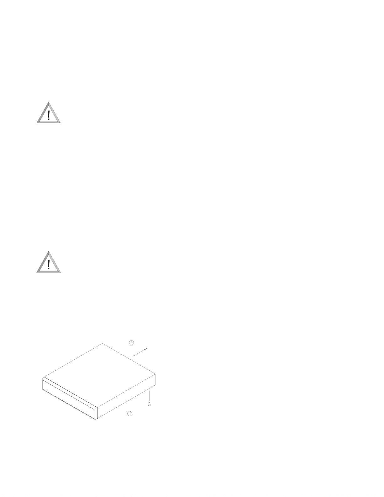
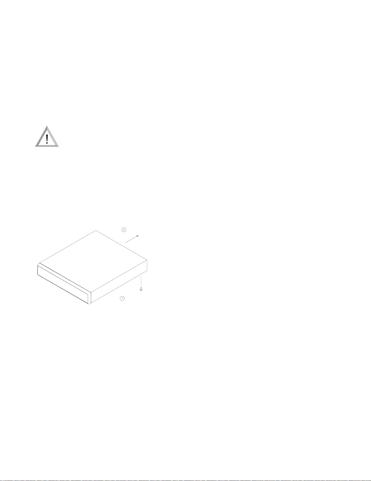
The top cover is fastened to the case by two screws located on
the bottom rear of the unit. Once the screws have been
removed, the cover slides back and off the unit. See Top Cover
Removal.
Top Cover Removal
4.4 Video Inputs
LTC 2272 Series Only: Each of the four camera inputs have a
single BNC connector and are 75 ohm terminated.
LTC 2276 Series Only: For each of the four camera inputs
there are two BNC connectors on the rear panel. One of these
connectors is to be used as a camera input while the other
connector may be used as a looping output. It does not matter
which connector is used as the camera input and which is used
as the looping output. DIP switch S601 controls the 75 ohm
termination for each of the 4 video inputs. S601 is switched
ON for 75 ohm termination or OFF for nonterminated
(looping operation). The factory default is set for 75 ohm
terminated operation. These settings should only be done by a
qualified installer or service center. The cover must be removed
to make the DIP switch adjustments. See Cover Removal and
DIP Switch and Resistor Location - LTC 2276 Series
illustrations.
4.5 Monitor Outputs
The LTC 2272 Series provide a single video output which will
display a quad view of the video inputs.
The LTC 2276 Series provide two monitor outputs. The
VIDEO OUT is a full function output providing Sequence,
Quad, Full View, Freeze, Alarm, and Video Loss operations.
The QUAD VIDEO OUT provides a quad view, quad view
with freeze, and full view with zoom-freeze operations.
The monitor outputs must be terminated into a 75 ohm load.
If the monitor output line is looped through monitors or other
equipment, be sure the monitor terminations are set to Hi-Z.
Only the last unit on the line should have its termination set to
75 ohm.
4.6 Camera Phase/Update Rate
The LTC 2272 Series and LTC 2276 Series achieve a real-time
update rate (30 frames-per-second) when they are used with
line-locked cameras that have a phase error of less than 5
degrees. This can be achieved by adjusting the phase adjustment
on the individual cameras. The phase adjustment should be
made before power is applied to the VidQuad®unit. If the
phase adjustment is made after power has been applied to the
unit, the unit should be momentarily disconnected from the
power source then reconnected to the power source to
synchronize the unit with the cameras. The unit-to-camera
synchronization will automatically be initiated when a camera is
connected to an unused video input. If this procedure is not
followed, or if the cameras are not line-locked together with ± 5
degrees phase, the update rate of the unit will be one-half realtime, or 15 frames-per-second.
Slide Cover Back
Remove Screws From
Bottom Rear Corners
S936A01AE
(2) Places
Page 8

1.4
4.7 Alarm Inputs and Output
(Accessory Output)
For LTC 2276 Series: One 150 mm (6 in) cable, with a 15 pin
connector at one end (supplied with the VidQuad®unit), is for
connecting external devices such as alarm inputs and outputs,
and accessories.
4.8 Alarm Inputs
LTC 2276 Series only: The alarm inputs are configured to be
normally open.
CAUTION: Do not apply external voltages to the
alarm inputs.
Use only isolated closures or open collector logic. Precautions
should be taken, particularly on long runs, to prevent pickup of
spurious signals from associated wiring which may give false
inputs or damage the unit.
4.9 Alarm Output
LTC 2276 Series only: The alarm output is a relay which is
configured to be normally open. The relay contacts can handle
up to 0.5 amperes at 20 volts AC/DC (up to 36 volts peak
voltage from either pin of relay to ground), and a maximum
resistive load of 10 VA.
4.10 Video Loss Output
LTC 2276 Series only: The video loss output is a logic level
output that is active low on video loss. Refer to PINOUTS -
Alarm/Accessory illustration.
4.11 Remote Control Inputs
LTC 2276 Series only: Remote control contact closure inputs
are provided to mimic the operation of the following front
panel buttons: QUAD, FULL VIEW 1, FULL VIEW 2, FULL
VIEW 3, FULL VIEW 4, and SEQUENCE. Refer to Pinouts
Alarm/Accessory illustration.
4.12 Connections
The following connections should be made prior to applying
power to the unit:
1. Connect the appropriate video signals to inputs labeled
CAM 1 through 4.
2. LTC 2272 Series: Connect the main monitor to the QUAD
VIDEO OUT output. See Typical Application - LTC 2272
Series illustration.
LTC 2276 Series: Connect the main monitor to the
VIDEO OUT output, and the second monitor to the
QUAD VIDEO OUT output. See Typical Application -
LTC 2276 Series illustration.
3. Plug the power cord into an AC power source.
5 OPERATION
5.1 LTC 2272 Series
When power is applied to the unit, the ON LED lights, and the
main monitor displays four quadrants on the screen
corresponding to the four video inputs.
See Front Panel - LTC 2272 Series and Typical Application -
LTC 2272 Series illustrations.
5.2 LTC 2276 Series
When power is applied to the unit, both the QUAD VIDEO
OUT and the VIDEO OUT monitors will be in the quad
display mode.
NOTE: Upon power-up and upon any system reset, the
system's software revision and the unit's model number will be
reported in two separate screens.
Other advisory messages may occur dependent upon various
conditions, such as VIDEOLOSS, ALARM, FRZ, and OLD
FRZ.
See Front Panel - LTC 2276 Series and Typical Application LTC 2276 Series illustrations.
5.2.1 Front Panel Controls
SEQUENCE: Enables the sequence operation.
QUAD: Displays the quad video screen (four separate cameras
in one screen).
FULL VIEW: Used to select one of the four video inputs and
display it in a live full screen mode.
FREEZE: Used to digitally freeze and unfreeze the
corresponding quadrant of the quad screen.
5.2.2 Operating Modes
Sequence Mode
When the SEQUENCE key is pressed, the VIDEO OUT
monitor shall start the sequence between the four video inputs,
and the QUAD screen with a 2 second dwell time. See Quad
Sequence Enable. The on-screen text SEQ will be displayed at
the bottom center of the screen. The FULL VIEW LED above
the video that is currently being displayed, or the QUAD LED
if the quad screen is being displayed, will light. There will be
no change to the QUAD VIDEO OUT monitor display during
normal sequence operation.
The following keys are functional for the sequence mode:
SEQUENCE will stop and start the sequence operation.
QUAD will stop the sequencing and switch the VIDEO OUT
monitor to the Quad Screen Mode.
FULL VIEW will stop the sequencing and switch the VIDEO
OUT monitor to the full screen display of the corresponding
video input.
Page 9

1.5
FREEZE will freeze any of the four video images corresponding
to the button pressed.
Quad Screen Mode
When the QUAD button is pressed, the VIDEO OUT and
QUAD VIDEO OUT monitors shall display a quad image that
contains the quarter-sized images from the four video inputs.
Each of the four quadrants displayed on the VIDEO OUT
monitor has an on-screen camera identification number
corresponding to the video input number (1-4).
The following keys are functional when in the Quad mode:
QUAD will toggle the screen mode displayed on the VIDEO
OUT monitor between the quad screen and the previous screen
displayed.
SEQUENCE will switch the VIDEO OUT monitor to the
sequence mode.
FULL VIEW will switch the VIDEO OUT monitor to a full
screen display of the video that corresponds to the FULL VIEW
button pressed.
FREEZE will freeze one of the four video images corresponding
to the button pressed.
Full Screen Mode
When one of the FULL VIEW buttons is pressed, the VIDEO
OUT monitor will display a full screen of the video that
corresponds to the FULL VIEW button pressed. If the selected
video is frozen, the frozen video will be zoomed to fill the entire
screen, and the text ZOOM FRZ will be displayed. The FULL
VIEW LED that corresponds to the video displayed on the
VIDEO OUT monitor will light.
The following keys are functional when in the Full Screen
Mode:
SEQUENCE will switch the VIDEO OUT monitor to the
Sequence Mode.
QUAD will switch the VIDEO OUT monitor to Quad Screen
Mode.
FREEZE will freeze one of the four video images corresponding
to the button pressed.
Freeze Mode
When any of the FREEZE buttons are pressed, the VIDEO
OUT, and QUAD VIDEO OUT monitors will freeze the video
image corresponding to the button(s) pressed, and flash the
LED above the FREEZE button(s). When a quadrant is frozen,
a flashing icon will be displayed in that quadrant on both the
VIDEO OUT, and QUAD VIDEO OUT monitors. The
VIDEO OUT monitor will also display the flashing on-screen
text FRZ in each of the frozen quadrants.
The following keys are functional when in the FREEZE Mode:
SEQUENCE will switch the VIDEO OUT monitor to the
Sequence Mode.
QUAD will switch the VIDEO OUT monitor to Quad Screen
Mode.
FULL VIEW will switch the VIDEO OUT monitor to a full
screen display of the video that corresponds to the FULL VIEW
button pressed. The FULL VIEW LED that corresponds to the
video displayed on the VIDEO OUT monitor will light. If the
selected video is frozen, the frozen video will be zoomed to fill
the entire screen on both the VIDEO OUT, and QUAD
VIDEO OUT monitors The text ZOOM FRZ will be
displayed on the VIDEO OUT monitor. A flashing icon will
be displayed on the QUAD VIDEO OUT monitor.
Subsequent pressing of the corresponding FULL VIEW button
will toggle between the frozen image and a live image on the
VIDEO OUT monitor and toggle between the full screen
frozen zoomed image and the quad view on the QUAD
VIDEO OUT monitor.
FREEZE will clear the frozen image corresponding to the
button pressed.
Alarm Mode
An alarm event is triggered when a contact closure is applied to
one of the four external alarm input lines; see Pinouts -
Alarm/Accessory illustration. When an alarm event is triggered,
the VIDEO OUT monitor will display the full screen video of
the camera in alarm. In the event of multiple alarm inputs, the
VIDEO OUT monitor will sequence between each alarmed
video at a dwell time of two seconds. The flashing on-screen
text ALARM is added to the display of the video inputs for
which there is an alarm event. The QUAD OUT monitor will
display a quad view with a frozen image of the camera that is in
alarm. If the Quad Sequence is enabled (See Quad Sequence
Enable), the quad view, with the frozen image, will be added to
the alarm sequence on the VIDEO OUT monitor. If the
camera input was frozen prior to the alarm, the display will flash
on-screen text OLD FRZ along with the ALARM text. In the
alarm mode, the FREEZE buttons are not functional. Any
OLD FRZ images can not be cleared until the alarm clears. The
alarm event will last for the duration of the contact closure with
a minimum duration of 10 seconds (alarm capture time). An
alarm relay output provides a contact closure for the duration of
the alarm event. See Pinouts - Alarm/Accessory illustration.
The following keys are functional for the Alarm mode:
SEQUENCE will clear all alarm events and put the system back
to previous mode before the alarm(s) occurred.
QUAD will clear all alarm events and put the system back to
previous mode before the alarm(s) occurred.
FULL VIEW will clear all alarm events and put the system back
to previous mode before the alarm(s) occurred.
Page 10

1.6
Video Loss
This unit has the ability to detect the loss of sync caused by a
cut or disconnected video cable. If the sync is lost for any
camera for which the video loss function is enabled, the video
loss open collector transistor output will be asserted low for 10
seconds, after which it will be +5 volt logic-high. When there is
a video loss, the unit will display the quad video screen format
on the VIDEO OUT monitor; the following information will
be displayed in each quadrant that has a video loss:
The on-screen text VIDLOSS is displayed in the quadrant.
The flashing icon is displayed on both the VIDEO OUT
and QUAD VIDEO OUT monitors.
The FREEZE LED corresponding to the video input under
video loss flashes.
NOTE: If the unit is powered up while there is loss of sync, the
flashing icon will not be visible since the quadrant will become
white and be the same color as the flashing icon.
CAUTION: The following special setups should
only be done by an authorized service center or
installer.
5.2.4 Quad-Sequence Enable
The quad screen will be sequenced with the four full-screen
video inputs with resistor R259 installed. If R259 is removed,
the quad screen will not be included in the sequence. As factory
default, the unit is shipped with R259 installed. The cover must
be removed to access R259. Refer to Cover Removal and DIP
Switch and Resistor Locations - LTC 2276 Series illustrations.
5.2.5 Video Loss Defeat
Internal DIP switch S201 can be used to defeat the video loss
function of the video inputs. The cover must be removed to
access S201. See Cover Removal and DIP Switch and Resistor
Locations - LTC 2276 Series illustrations. This is used if less
than four cameras are to be connected to the unit. The factory
default is video loss enabled for all four video inputs.
When all four cameras are used, all four positions of the S201
should be open (OFF).
When three cameras are used, they should be connected to video
inputs 1-3, and S201 position 1 should be closed (ON) to
defeat the video loss for 1 video input (4).
When two cameras are used, they should be connected to video
inputs 1-2, and S201 position 2 should be closed (ON) to
defeat the video loss for 2 video inputs (3, 4).
When only one camera is used, it should be connected to video
input 1, and S201 position 3 should be closed (ON) to defeat
the video loss for 3 video inputs (2, 3, 4).
When S201 position 4 is closed (ON), the video loss is defeated
for all four video inputs.
IMPORTANT: Only one position of S201 can be closed
(ON) at a time.
Page 11
1.7
6 ILLUSTRATIONS
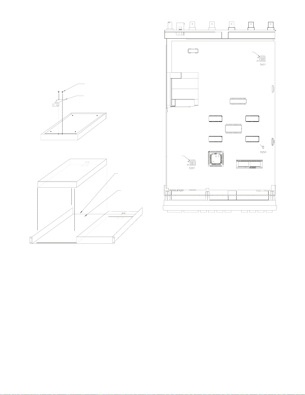
6.1 Additional Rack Mounting Instructions When
Using LTC 9101/00 Rack Kit
Attach the supplied U-bracket to the underside of the unit using
the two 6-32 x 5/16 inch screws provided. Hook the free end of
the bracket over the rear lip of the rack. Secure bracket to rear
lip of rack using the remaining two screws.
Rack Mounting
Switch and Resistor Location - LTC 2276 Series
6-32 x 5/16 Screw
Hold-down
Bracket
Transformer
DIP
Switch
DIP
Switch
Resistor
Rear Shelf Lip
Rack
Shelf
S9608023AE
NOTE: Most Components Removed ForClarity
S9406001BE
Page 12
1.8
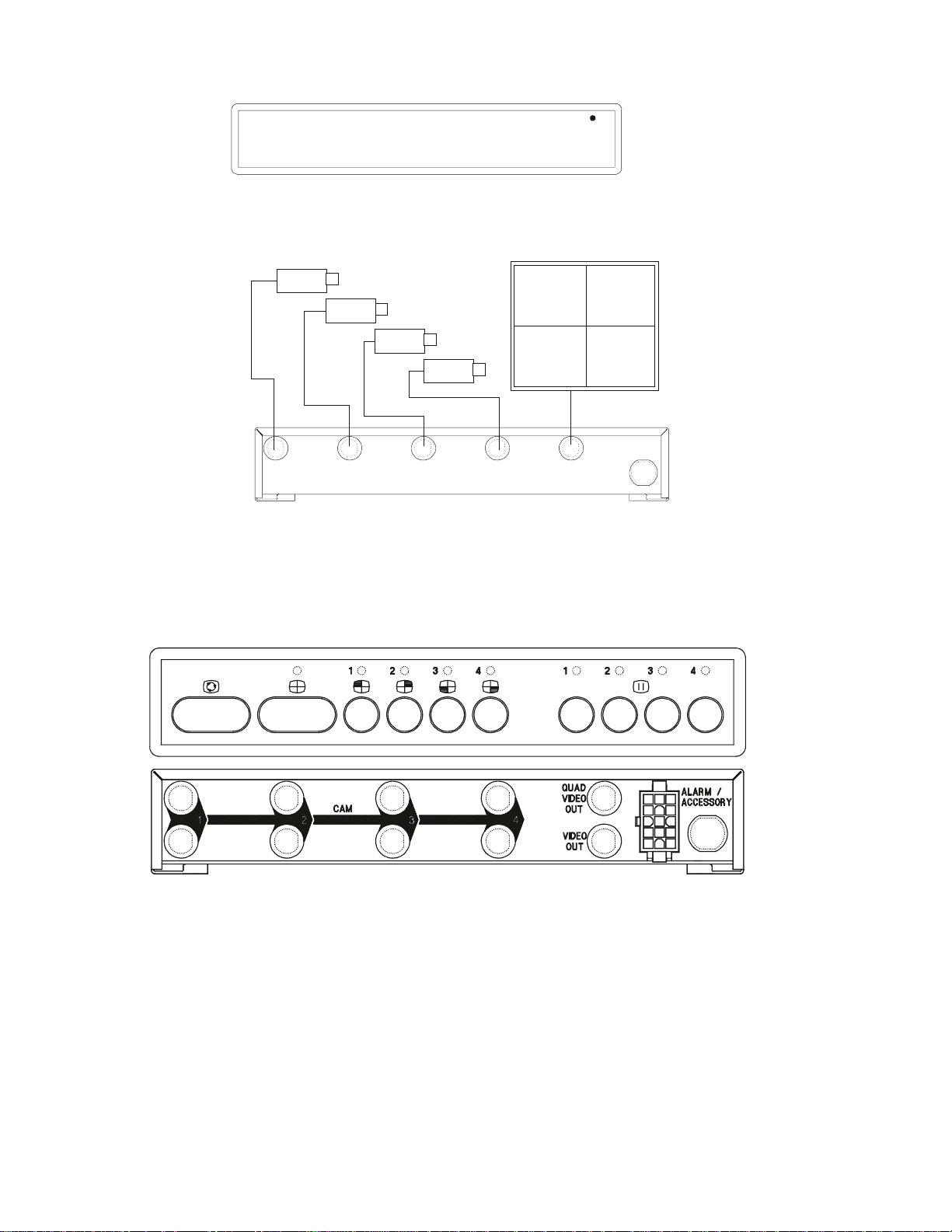
Front Panel - LTC 2272 Series
Typical Application - LTC 2272 Series
Front and Back Panel - LTC 2276 Series
Camera 1
Video 1
Camera 2
ON
S9404002AE
Video 2
Camera 3
Video 3
Camera 4
CAM 1
CAM 2 CAM 3
CAM 4
Video 4
Main Monitor
QUAD
VIDEO
OUT
S9404003AE
Page 13
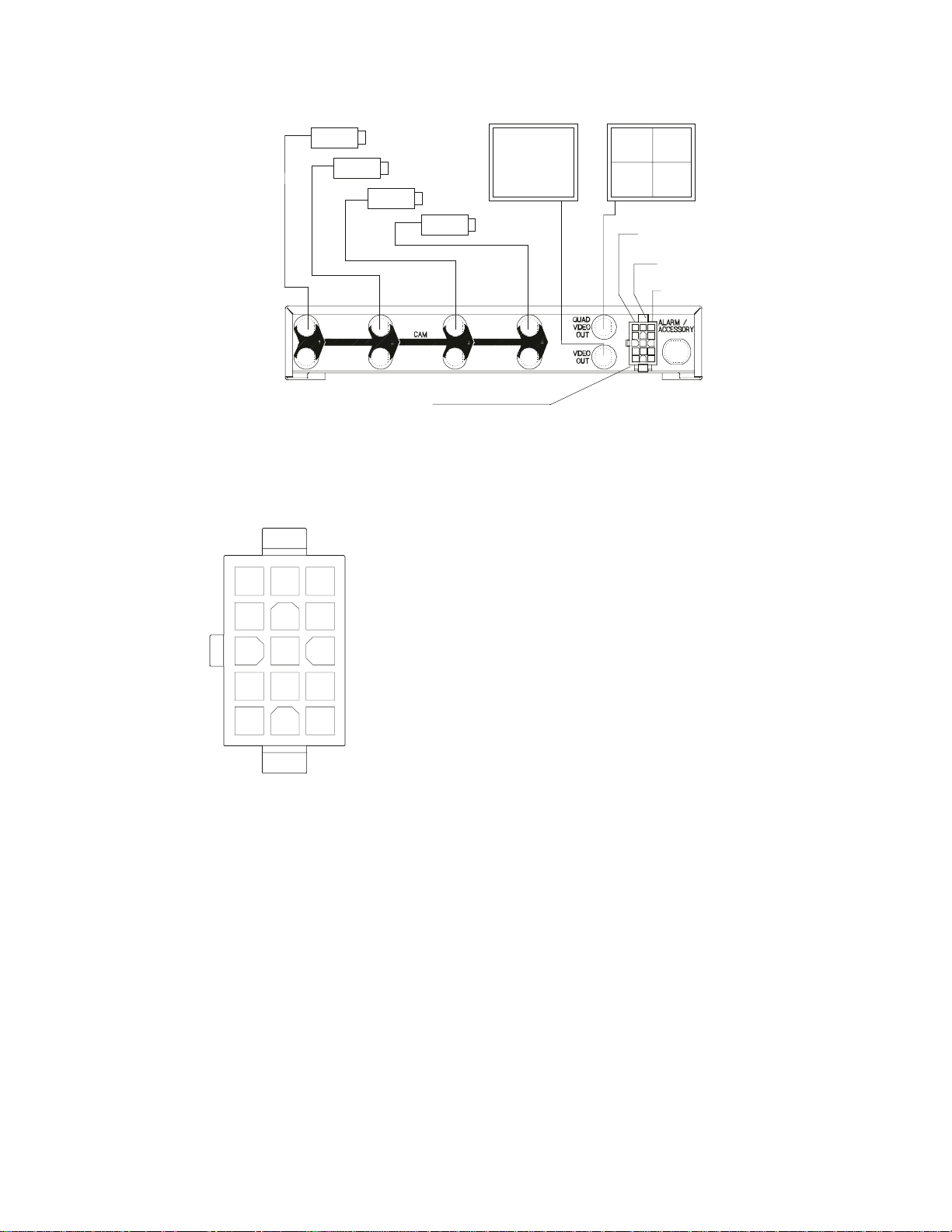
Typical Application - LTC 2276 Series
1.9
Camera1
Pinouts - Alarm/Accessory
Pin No. Designation Input/Output
1 Alarm 1 Input
2 Alarm 2 Input
3 Alarm 3 Input
4 Alarm 4 Input
5 Relay Contact A Output
6 Relay Contact B Output
7 Remote QUAD Input
8 Remote FULL VIEW 1 Input
9 Remote FULL VIEW 2 Input
10 Remote FULL VIEW 3 Input
11 Remote FULL VIEW 4 Input
12 Ground N/A
13 Remote SEQUENCE Input
14 Video Loss Output
15 Ground N/A
Camera2
1
2
3
4
5
611
12
7
13
8
14
9
10
15
S9405013AE
Camera3
Remote
Operation
Camera4
Main Monitor
Second Monitor
4 Optional
Contact Closures
Inputs
Alarm Relay
Output
Video Loss
Output
S9404005AE
Page 14

1.10
Page 15
2.1
MESURES DE SÉCURITÉ
En raison d’une limitation de la place disponible, il est possible
que cette étiquette soit apposée sur le dessous de l’appareil.
L’éclair fléché dans un triangle équilatéral avertit
l’utilisateur de la présence d’une “tension
dangereuse” non isolée à l’intérieur de l’appareil et
d’une valeur suffisante pour présenter un risque
d’électrocution aux personnes.
Le point d’exclamation contenu dans un triangle
équilatéral avertit l’utilisateur de la présence de
consignes d’utilisation et de maintenance
importantes dans la documentation qui
accompagne l’appareil.
Attention: L’installation ne doit être effectuée que
par un personnel technique qualifié conformément
à la réglementation du Code Électrique National
ou à la réglementation locale pertinente.
Disjonction de l’alimentation. Les appareils avec
ou sans commutateurs ON-OFF sont alimentés à
chaque fois que le cordon d’alimentation est
branché à la source d’alimentation; toutefois, les
appareils disposant de commutateurs ON-OFF ne
fonctionnent que lorsque le commutateur ONOFF est dans la position ON. Le cordon
d’alimentation constitue le moyen de disjonction
de l’alimentation principale de tous les appareils.
DANGER: POUR ÉVITER TOUT RISQUE
D’ÉLECTROCUTION, VEUILLEZ NE PAS
OUVRIR LE BOÎTIER. IL N’Y A PAS DE PIÈCES
REMPLAÇABLES PAR L’UTILISATEUR À
L’INTÉRIEUR DU BOÎTIER. POUR TOUTE
MAINTENANCE, VEUILLEZ VOUS ADRESSER
À UN TECHNICIEN SPÉCIALISÉ.
ATTENTION: POUR ÉVITER TOUT RISQUE
D’ÉLECTROCUTION OU D’INCENDIE,
VEUILLEZ NE PAS EXPOSER À LA PLUIE OU À
L’HUMIDITÉ UN APPAREIL NON CONÇU
POUR UNE UTILISATION EXTÉRIEURE.
ATTENTION
RISQUE D'ÉLECTROCUTION.
NE PAS OUVRIR
Page 16
2.2
SOMMAIRE
1 DÉBALLAGE . . . . . . . . . . . . . . . . . . . . . . . . . . . . . 2.2
2 SERVICE . . . . . . . . . . . . . . . . . . . . . . . . . . . . . . . . 2.2
3 DESCRIPTION . . . . . . . . . . . . . . . . . . . . . . . . . . . 2.2
4 INSTALLATION . . . . . . . . . . . . . . . . . . . . . . . . . . 2.2
4.1 Alimentation électrique. . . . . . . . . . . . . . . . . . . . . . . 2.2
4.2 Montage . . . . . . . . . . . . . . . . . . . . . . . . . . . . . . . . . 2.3
4.3 Retrait du couvercle . . . . . . . . . . . . . . . . . . . . . . . . . 2.3
4.4 Entrées vidéo . . . . . . . . . . . . . . . . . . . . . . . . . . . . . . 2.3
4.5 Sorties de moniteur . . . . . . . . . . . . . . . . . . . . . . . . . 2.3
4.6 Taux de rafraîchissement/phase des caméras. . . . . . . . 2.3
4.7 Entrées et sortie d'alarme (sortie d'accessoire) . . . . . . 2.4
4.8 Entrées d'alarme. . . . . . . . . . . . . . . . . . . . . . . . . . . . 2.4
4.9 Sortie d'alarme. . . . . . . . . . . . . . . . . . . . . . . . . . . . . 2.4
4.10 Sortie de perte de signal vidéo. . . . . . . . . . . . . . . . . . 2.4
4.11 Entrées de télécommande. . . . . . . . . . . . . . . . . . . . . 2.4
4.12 Connexions . . . . . . . . . . . . . . . . . . . . . . . . . . . . . . . 2.4
5 FONCTIONNEMENT . . . . . . . . . . . . . . . . . . . . . 2.4
5.1 Série LTC 2272. . . . . . . . . . . . . . . . . . . . . . . . . . . . 2.4
5.2 Série LTC 2276. . . . . . . . . . . . . . . . . . . . . . . . . . . . 2.4
6 ILLUSTRATIONS . . . . . . . . . . . . . . . . . . . . . . . . . 2.7
1 DÉBALLAGE
Veuillez procéder avec précaution lors du déballage. Ce matériel
est de type électronique et il doit être manipulé avec soin.
Veuillez contrôler la présence des éléments suivants:
1. Un appareil de type LTC 2272/60, LTC 2272/50,
LTC 2276/60 ou LTC 2276/50.
2. Un étrier (pour l'utilisation avec le kit de châssis optionnel
LTC 9101/00).
3. Série LTC 2276 uniquement: Un câble ayant un connecteur
à 15 broches à une extrémité. (Utilisé pour les connexions
d'alarme/accessoire.)
Si un élément semble avoir été endommagé durant le transport,
veuillez le remettre correctement dans son carton et en informer
le transporteur. Si un ou plusieurs éléments sont manquants,
veuillez en informer le représentant commercial ou le bureau
d'assistance à la clientèle de Philips Communication & Security
Systems Inc.
Le carton d'emballage d'origine constitue le meilleur moyen
d'emballage pour le transport de l'appareil. Conservez-le à des
fins d'utilisation ultérieure.
2 SERVICE
Si l'appareil a besoin d'être réparé, le client est invité à contacter
le Centre Technique de Philips Communication & Security
Systems Inc. le plus proche afin d'obtenir une autorisation de
retour et des instructions d'expédition.
Les Centres Techniques
U.S.A. & Canada: 800-366-2283
Mexico & Amérique Centrale: 52-5-564-2726
Europe & Moyen-Orient: 44-1932-765666
Amérique du Sud: 54-1-956-0837
Australie: 61-2-888-9000
Nouvelle-Zélande: 64-4-237-7297
NOTE: Il est impératif de porter un bracelet de mise à la terre
et de prendre les précautions d'usage lors de la manipulation
des circuits imprimés sensibles aux décharges électrostatiques.
3 DESCRIPTION
Les processeurs vidéo des séries LTC 2272 et LTC 2276
effectuent une saisie numérique de l'intégralité des signaux vidéo
provenant de quatre sources. Ils réduisent ces images à une
taille équivalente au quart de l'écran et les combinent afin de
réaliser un affichage quadruple sur un même moniteur. Les
deux modèles acceptent aussi bien des images monochromes
qu'en couleurs. L'affichage quadruple résultant n'est disponible
qu'en monochromie. Toutes les entrées en couleurs arrivant sur
le modèle LTC 2276 sont affichées en couleurs dans le mode
plein écran. Le modèle LTC 2272 dispose de quatre entrées de
caméra et d'une sortie de moniteur. Le modèle LTC 2276
dispose de quatre entrées de caméra et de deux sorties de
moniteur.
4 INSTALLATION
4.1 Alimentation électrique
No. de modèle Tension nominale Puissance
nominale
1
LTC 2272/60 120 Vca, 50/60 Hz 8 W
LTC 2272/50 220-240 Vca, 50/60 Hz 8 W
LTC 2276/60 120 Vca, 50/60 Hz 9 W
LTC 2276/50 220-240 Vca, 50/60 Hz 9 W
1. À la tension nominale.
Disjonction de l'alimentation. Les appareils avec
ou sans commutateurs ON-OFF sont alimentés à
chaque fois que le cordon d'alimentation est
branché à la source d'alimentation; toutefois, les
appareils disposant de commutateurs ON-OFF ne
fonctionnent que lorsque le commutateur ONOFF est dans la position ON. Le cordon
d'alimentation constitue le moyen de disjonction
de l'alimentation principale de tous les appareils.
ATTENTION: DISPOSITIF SENSIBLE AUX
DÉCHARGES ÉLECTROSTATIQUES. VEUILLEZ
OBSERVER LES PRÉCAUTIONS D’USAGE
LORS DE LA MANIPULATION DES
DISPOSITIFS CMOS/MOSFET POUR ÉVITER
LES DÉCHARGES ÉLECTROSTATIQUES.
ATTENTION
VEUILLEZ OBSERVER LES
PRÉCAUTIONS D'USAGE LORS
DE LA MANIPULATION
DES DISPOSITIFS SENSIBLES
AUX DÉCHARGES
ÉLECTROSTATIQUES
Page 17
2.3
4.2 Montage
Les modèles des séries LTC 2272 et LTC 2276 sont destinés à
être posés sur un bureau. Pour le montage en châssis, il est
proposé un kit optionnel de montage en châssis portant la
référence LTC 9101/00.
Un étrier est livré avec l'appareil. Il est destiné à être utilisé à la
place de l'étrier fourni dans le kit optionnel de montage en
châssis LTC 9101/00. Veuillez vous reporter à la section
ILLUSTRATIONS. Si l'appareil n'est pas installé en châssis,
l'étrier fourni peut être ignoré.
4.3 Retrait du couvercle
ATTENTION: Le retrait du couvercle ne doit
être effectué que par un personnel technique
compétent - l'appareil ne contient aucune pièce
accessible à l'utilisateur. L'appareil doit toujours
être débranché avant de procéder au retrait du
couvercle et il doit rester débranché tant que le
couvercle n'a pas été remis en place.
Le couvercle supérieur est fixé au boîtier par deux vis situées à
l'arrière de l'appareil. Après que les vis aient été retirées, il est
possible de faire coulisser le couvercle vers l'arrière et de le
dégager. Veuillez consulter l'illustration Retrait du couvercle
supérieur.
Retrait du couvercle supérieur
4.4 Entrées vidéo
Série LTC 2272 uniquement: Chacune des quatre entrées de
caméra dispose d'un seul connecteur BNC et d'une terminaison
de 75 ohms.
Série LTC 2276 uniquement: Chacune des quatre entrées de
caméra dispose de deux connecteurs BNC sur le panneau
arrière. L'un de ces connecteurs doit être utilisé comme entrée
de caméra, tandis que l'autre peut être utilisé comme sortie de
bouclage. Chaque connecteur peut servir indifféremment
d'entrée de caméra ou de sortie de bouclage. L'interrupteur
DIP S601 contrôle la terminaison de 75 ohms pour chacune des
quatre entrées vidéo. S601 doit être dans la position ON pour
un fonctionnement avec terminaison de 75 ohms et dans la
position OFF pour un fonctionnement sans terminaison
(fonctionnement en bouclage). Le réglage d'usine par défaut est
pour un fonctionnement avec terminaison de 75 ohms. Ces
réglages ne doivent être effectués que par un installateur qualifié
ou dans un centre technique. Il est nécessaire de procéder au
retrait du couvercle pour effectuer les réglages des interrupteurs
DIP. Veuillez consulter les illustrations Retrait du couvercle et
Emplacement des interrupteurs DIP et des résistances LTC 2276.
4.5 Sorties de moniteur
Les modèles de la série LTC 2272 comportent une sortie vidéo
unique permettant un affichage quadruple des entrées vidéo.
Les modèles de la série LTC 2276 comportent deux sorties
vidéo. La fonction VIDEO OUT est une fonction complète de
sortie permettant d'effectuer des opérations suivantes: Séquence,
Affichage Quadruple, Plein Écran, Arrêt sur image, Alarme et
Perte de Signal Vidéo. La fonction QUAD VIDEO OUT
permet d'effectuer les opérations suivantes: Affichage
Quadruple, Arrêt sur Image Quadruple, Plein Écran avec
arrêt/zoom.
Les sorties de moniteur doivent se terminer sur une charge de
75 ohms. Si la ligne de sortie de moniteur est bouclée à travers
d'autres moniteurs ou d'autres dispositifs, veillez à ce que la
terminaison des moniteurs soit réglée sur Hi-Z. Seul le dernier
appareil de la ligne doit avoir une terminaison de 75 ohms.
4.6 Taux de rafraîchissement/phase de la caméra
Les détecteurs des séries LTC 2272 et LTC 2276 peuvent
fonctionner avec un taux de rafraîchissement en temps réel (30
images par seconde) lorsqu'ils sont utilisés avec des caméras
synchronisées en ligne et ayant une erreur de phase inférieure à
5 degrés. Ceci peut être obtenu en procédant à un réglage de la
phase des caméras individuelles. Le réglage de la phase doit être
effectué avant que l'appareil VidQuad®ne soit mis sous
tension. Si le réglage de phase est effectué après que l'appareil
ait été mis sous tension, il est nécessaire de le débrancher
momentanément de l'alimentation électrique, puis de le
rebrancher afin d'obtenir qu'il soit synchronisé avec les caméras.
La synchronisation détecteur/caméra est effectuée
automatiquement lorsqu'une caméra est raccordée à une entrée
vidéo non utilisée. Si cette procédure n'est pas respectée, ou si
les caméras ne sont pas toutes synchronisées en ligne les unes
avec les autres dans une plage de ± 5°, le taux de
rafraîchissement de l'appareil ne sera égal qu'à la moitié du taux
en temps réel, à savoir 15 images par seconde.
Faites coulisser le
couvercle vers l'arrière.
Retirez les vis se trouvant
S936A01AE
dans les coins arrières du
dessous du boîtier.
(2) emplacements.
Page 18

2.4
4.7 Entrées et sortie d'alarme (sortie d'accessoire)
Dans le cas de la série LTC 2276: Un câble de 150 mm (6
pouces), comportant un connecteur à 15 broches à une
extrémité (fourni avec le détecteur VidQuad®), est utilisé pour
le raccordement des dispositifs externes, comme les entrées et les
sorties d'alarme et d'accessoire.
4.8 Entrées d'alarme
Série LTC 2276 uniquement: Les entrées d'alarme sont
configurées de telle sorte qu'elles soient normalement ouvertes.
ATTENTION: Veuillez ne jamais appliquer de
tensions externes aux entrées d'alarme.
N'utilisez que des dispositifs ayant des contacts isolés ou des
dispositifs logiques à collecteur ouvert. Il est nécessaire de
prendre les précautions nécessaires, en particulier lorsque les
connexions se font sur de grandes distances, pour éviter que des
interférences ne puissent se produire avec les câblages associés,
ce qui pourrait entraîner des déclenchements inopinés des
entrées ou endommager l'appareil.
4.9 Sortie d'alarme
Série LTC 2276 uniquement: La sortie d'alarme est constituée
par un relais qui est configuré pour être normalement ouvert.
Les contacts du relais peuvent supporter jusqu'à 0,5 ampère sous
une tension de 20 volts ca/cc (avec une tension de pointe de 36
volts entre l'une quelconque des broches du relais et la masse),
et une charge résistive maximale de 10 VA.
4.10 Sortie de perte de signal vidéo
Série LTC 2276 uniquement: La sortie de perte de signal vidéo
est une sortie de niveau logique qui est à l'état bas actif lors de la
perte du signal vidéo. Veuillez vous référer à l'illustration
BROCHAGES - Alarme/Accessoire.
4.11 Entrées de télécommande
Série LTC 2276 uniquement: Des entrées de télécommande à
fermeture de contacts sont disponibles afin de dupliquer le
fonctionnement des touches suivantes du panneau avant:
QUAD, FULL VIEW 1, FULL VIEW 2, FULL VIEW 3,
FULL VIEW 4 et SEQUENCE. Veuillez vous référer à
l'illustration BROCHAGES - Alarme/Accessoire.
4.12 Connexions
Les connexions suivantes doivent être réalisées avant de mettre
l'appareil sous tension:
1. Connectez les signaux vidéo appropriés aux entrées
répertoriées CAM 1 à 4.
2. Série LTC 2272: Connectez le moniteur principal à la sortie
QUAD VIDEO OUT. Veuillez vous référer à l'illustration
Application type - série LTC 2272.
Série LTC 2276: Connectez le moniteur principal à la sortie
VIDEO OUT et le second moniteur à la sortie QUAD
VIDEO OUT. Veuillez vous référer à l'illustration
Application type - série LTC 2276.
3. Connectez le cordon d'alimentation dans une prise
d'alimentation électrique du secteur.
5 FONCTIONNEMENT
5.1 Série LTC 2272
Lorsque l'appareil est mis sous tension, la diode LED rouge ON
s'allume et le moniteur principal affiche quatre secteurs sur
l'écran, qui correspondent aux quatre entrées vidéo.
Veuillez vous référer aux illustrations Panneau avant - série
LTC 2272 et Application type - série LTC 2272.
5.2 Série LTC 2276
Lorsque l'appareil est mis sous tension, les deux moniteurs
QUAD VIDEO OUT et VIDEO OUT sont dans le mode
d'affichage quadruple.
NOTE: Lors de la mise sous tension et à chaque réinitialisation
du système, le numéro de révision du logiciel et le numéro de
modèle de l'appareil sont affichés dans deux écrans différents.
Il est possible que d'autres messages d'information soient
affichés selon les circonstances, comme VIDEOLOSS, ALARM,
FRZ et OLD FRZ.
Veuillez vous référer aux illustrations Panneau avant - série
LTC 2276 et Application type - série LTC 2276.
5.2.1 Commandes du panneau avant
SEQUENCE: Cette commande active le fonctionnement en
mode de séquence.
QUAD: Cette commande active le mode d'affichage quadruple
(quatre caméras distinctes sur un même écran).
FULL VIEW: Cette commande sélectionne l'une des quatre
entrées vidéo et l'affiche en mode plein écran.
FREEZE: Cette commande a pour effet d'arrêter et de remettre
en mouvement l'image numérisée sur le secteur correspondant
de l'écran quadruple.
5.2.2 Modes de fonctionnement
Mode de séquence (Sequence mode)
Lorsque la touche SEQUENCE est appuyée, le moniteur
VIDEO OUT commence la séquence d'affichage comprenant
les quatre entrées vidéo et l'écran QUAD avec un temps d'arrêt
momentané de 2 secondes. Veuillez vous reporter à la section
Activation de la séquence Quad. Le texte SEQ est affiché au
centre inférieur de l'écran. La diode FULL VIEW se trouvant
au dessus du signal vidéo qui est actuellement affiché, ou la
diode QUAD si l'écran QUAD est affiché, s'allume. Le
fonctionnement du moniteur QUAD VIDEO OUT ne subit
aucun changement lors du fonctionnement en mode de
séquence normal.
Les touches suivantes sont actives lors du fonctionnement en
mode de séquence:
Page 19

2.5
SEQUENCE: Cette touche lance et interrompt l'exécution de la
séquence.
QUAD: Cette touche interrompt l'exécution de la séquence et
fait passer le moniteur VIDEO OUT dans le mode d'écran
quadruple (Quad Screen Mode).
FULL VIEW: Cette touche interrompt l'exécution de la
séquence et fait passer le moniteur VIDEO OUT en mode plein
écran afin d'afficher l'entrée vidéo correspondante.
FREEZE: Cette touche permet d'effectuer un arrêt sur image de
l'entrée vidéo correspondant à la touche appuyée.
Mode d'affichage quadruple (Quad Screen Mode)
Lors de l'appui de la touche QUAD, les moniteurs VIDEO
OUT et QUAD VIDEO OUT affichent une image quadruple
qui contient des images réduites au quart des quatre entrées
vidéo. Chacun des quatre secteurs affichés sur le moniteur
VIDEO OUT comprend un numéro d'identification de caméra
correspondant au numéro de l'entrée vidéo (1-4).
Les touches suivantes sont actives lors du fonctionnement en
mode d'affichage quadruple:
QUAD: Cette touche fait basculer l'affichage du moniteur
VIDEO OUT entre le mode d'écran quadruple et l'écran
précédemment affiché.
SEQUENCE: Cette touche fait passer le moniteur VIDEO
OUT dans le mode de séquence.
FULL VIEW: Cette touche fait passer le moniteur VIDEO
OUT dans le mode plein écran pour afficher le signal vidéo
correspondant à la touche FULL VIEW appuyée.
FREEZE: Cette touche fait effectuer un arrêt sur l'image à celui
des quatre signaux vidéo correspondant à la touche appuyée.
Mode plein écran (Full Screen Mode)
Lorsque l'une des quatre touches FULL VIEW est appuyée, le
moniteur VIDEO OUT affiche en plein écran le signal vidéo
correspondant à la touche FULL VIEW appuyée. Si l'image du
signal vidéo sélectionné est arrêtée, celle-ci est agrandie afin de
remplir complètement l'écran et le texte ZOOM FRZ est
affiché. La diode FULL VIEW correspondant au signal vidéo
affiché sur le moniteur VIDEO OUT s'allume.
Les touches suivantes sont actives lors du fonctionnement en
mode d'affichage plein écran:
SEQUENCE: Cette touche fait passer le moniteur VIDEO
OUT dans le mode de séquence.
QUAD: Cette touche fait passer le moniteur VIDEO OUT
dans le mode d'affichage quadruple.
FREEZE: : Cette touche fait effectuer un arrêt sur l'image à celui
des quatre signaux vidéo correspondant à la touche appuyée.
Mode d'arrêt sur image (Freeze Mode)
Lorsque l'une des touches FREEZE est appuyée, les moniteurs
VIDEO OUT et QUAD VIDEO OUT effectuent un arrêt sur
l'image du signal vidéo correspondant à la ou les touches
appuyées, et la diode LED se trouvant au dessus de la ou les
touches FREEZE appuyées se met à clignoter. Lorsque l'image
affichée dans un quadrant est arrêtée, une icone se met à
clignoter dans le secteur correspondant sur les deux moniteurs
VIDEO OUT et QUAD VIDEO OUT. Le moniteur VIDEO
OUT affiche également le texte clignotant FRZ dans chacun des
secteurs contenant une image arrêtée.
Les touches suivantes sont actives lors du fonctionnement en
mode d'arrêt sur l'image (FREEZE):
SEQUENCE: Cette touche fait passer le moniteur VIDEO
OUT dans le mode de séquence.
QUAD: Cette touche fait passer le moniteur VIDEO OUT
dans le mode d'affichage quadruple
FULL VIEW: Cette touche fait afficher une image en plein
écran sur le moniteur VIDEO OUT correspondant au signal
vidéo de la touche FULL VIEW appuyée. La diode FULL
VIEW correspondant au signal vidéo affiché sur le moniteur
VIDEO OUT s'allume. Si le signal vidéo sélectionné est arrêté
sur l'image, celle-ci est agrandie afin de remplir complètement
l'écran des moniteurs VIDEO OUT et QUAD VIDEO OUT,
et le texte ZOOM FRZ est affiché sur le moniteur VIDEO
OUT. Un icone clignotant est affichée sur le moniteur QUAD
VIDEO OUT. Les appuis suivants de la touche FULL VIEW
correspondante font basculer l'affichage entre l'image arrêtée et
l'image en direct sur le moniteur VIDEO OUT, et entre l'image
arrêtée agrandie en plein écran et l'affichage quadruple sur le
moniteur QUAD VIDEO OUT.
FREEZE: Cette touche libère l'image arrêtée correspondant à la
touche appuyée.
Mode d'alarme
Une alarme est déclenchée lorsqu'une fermeture de contacts se
produit sur l'une des quatre lignes d'entrée d'alarme externe;
Veuillez vous référer à l'illustration BROCHAGES -
Alarme/Accessoire. Lorsqu'une alarme est déclenchée, le
moniteur VIDEO OUT affiche le signal vidéo en plein écran de
la caméra en état d'alarme. Dans le cas de l'activation
simultanée de plusieurs entrées d'alarme, le moniteur VIDEO
OUT affiche l'une après l'autre chacune des entrées en état
d'alarme avec un temps d'arrêt momentané de 2 secondes. Le
texte clignotant ALARM est ajouté à l'affichage des entrées
vidéo qui correspondent aux alarmes. Le moniteur QUAD
OUT affiche un écran quadruple comportant une image arrêtée
de la caméra en état d'alarme. Si le mode de séquence quadruple
est activé (Voir Activation de séquence quadruple), l'écran
quadruple, ainsi que l'image arrêtée, sera ajouté à la séquence
d'alarme affichée sur le moniteur VIDEO OUT. Si l'image de la
caméra en état d'alarme était arrêtée avant que l'alarme ne se
produise, le texte clignotant OLD FRZ est affiché
conjointement au texte ALARM. Dans le mode d'alarme, les
Page 20

2.6
touches FREEZE ne sont pas opérationnelles. Les images OLD
FRZ ne peuvent pas être effacées tant que l'alarme n'a pas été
acquittée. L'état d'alarme continue tant que la fermeture des
contacts est maintenue, avec une durée minimale de 10
secondes (temps de saisie d'alarme). Une sortie de relais
d'alarme assure une fermeture de contacts pendant la durée de
l'alarme. Veuillez vous référer à l'illustration BROCHAGES -
Alarme/Accessoire.
Les touches suivantes sont actives lors du fonctionnement en
mode d'alarme:
SEQUENCE: Cette touche acquitte toutes les alarmes et remet
le système dans le mode où il se trouvait avant que la ou les
alarmes ne se produisent.
QUAD: Cette touche acquitte toutes les alarmes et remet le
système dans le mode où il se trouvait avant que la ou les
alarmes ne se produisent.
FULL VIEW: Cette touche acquitte toutes les alarmes et remet
le système dans le mode où il se trouvait avant que la ou les
alarmes ne se produisent.
Perte de signal vidéo
Cet appareil possède la faculté de détecter la perte de
synchronisation résultant de la coupure ou de la déconnexion
d'un câble de signal vidéo. S'il se produit une perte du signal de
synchronisation de toute caméra pour laquelle la fonction de
perte de signal vidéo est activée, la sortie par transistor à
collecteur ouvert de la fonction de perte de signal vidéo est
forcée à l'état bas pendant 10 secondes, à la suite de quoi elle
passe au niveau logique haut de +5 volts. Lorsqu'il se produit
une perte du signal vidéo, l'appareil affiche un écran vidéo
quadruple sur le moniteur VIDEO OUT; l'information
suivante est affichée dans chaque quadrant où il s'est produit
une perte du signal vidéo:
Le texte VIDLOSS est affiché dans le quadrant
correspondant de l'écran.
L'icone clignotante est affichée sur les deux moniteurs
VIDEO OUT et QUAD VIDEO OUT.
La diode FREEZE correspondant à l'entrée vidéo ayant subi
la perte de signal vidéo se met à clignoter.
NOTE: Si l'appareil est sous tension au moment où il se
produit une perte de synchronisation, l'icone clignotante ne sera
pas visible, car le secteur devient blanc et donc de la même
couleur que l'icone clignotante.
ATTENTION: Les réglages spéciaux suivants ne
doivent être effectués que par un personnel
technique agréé ou par l'installateur.
5.2.4 Activation de la séquence quadruple
L'écran quadruple est affiché en alternance avec les quatre écrans
pleins des signaux d'entrée lorsque la résistance R259 est
installée. Si la résistance R259 est retirée, l'écran quadruple n'est
pas inclus dans la séquence. Dans la configuration d'usine par
défaut, la résistance R259 est installée. Il est nécessaire de
procéder au retrait du couvercle pour accéder à la résistance
R259. Veuillez vous référer aux illustrations Retrait du
couvercle et Emplacement des interrupteurs DIP et des
résistances - Série LTC 2276.
5.2.5 Inhibition de la fonction de perte de signal vidéo
L'interrupteur DIP interne S201 peut être utilisé pour inhiber la
fonction de perte de signal vidéo des entrées vidéo. Il est
nécessaire de procéder au retrait du couvercle pour accéder à
l'interrupteur S201. Veuillez vous référer aux illustrations
Retrait du couvercle et Emplacement des interrupteurs DIP et
des résistances - Série LTC 2276. Cette procédure est mise en
oeuvre lorsque le nombre des caméras connectées à l'appareil est
inférieur à quatre. La configuration d'usine par défaut
comprend l'activation de la fonction de perte de signal vidéo des
quatre entrées vidéo.
Lorsque toutes les quatre caméras sont utilisées, les quatre positions
de l'interrupteur S201 doivent être ouvertes (OFF).
Lorsque trois caméras seulement sont utilisées, elles doivent être
connectées aux entrées vidéo 1-3 et la position 1 de
l'interrupteur S201 doit être fermée (ON) afin d'inhiber la perte
de signal vidéo d'une entrée vidéo (4).
Lorsque deux caméras seulement sont utilisées, elles doivent être
connectées aux entrées vidéo 1-2 et la position 2 de
l'interrupteur S201 doit être fermée (ON) afin d'inhiber la perte
de signal vidéo de deux entrées vidéo (3, 4).
Lorsqu'une caméra seulement est utilisée, elle doit être connectée à
l'entrée vidéo 1 et la position 3 de l'interrupteur S201 doit être
fermée (ON) afin d'inhiber la perte de signal vidéo de trois
entrées vidéo (2, 3, 4).
Lorsque la position 4 de l'interrupteur S201 est fermée (ON), la
fonction de perte de signal vidéo est inhibée pour l'ensemble des
quatre entrées vidéo.
IMPORTANT: Une seule position de l'interrupteur S201 doit
être fermée (ON) à la fois.
Page 21

2.7
6 ILLUSTRATIONS
6.1 Instructions supplémentaires de montage en
châssis lors de l'utilisation du kit de châssis
LTC 9101/00
Veuillez fixer l'étrier en U fourni au dessous de l'appareil en
utilisant les deux vis 6-32 x 5/16" fournies. Engagez l'extrémité
libre de l'étrier dans le rebord arrière du châssis. Fixez l'étrier au
rebord arrière du châssis en utilisant les deux vis restantes.
Montage en châssis
Emplacement des interrupteurs et des résistances -
Série LTC 2276
6-32 x 5/16 Screw
Hold-down
Bracket
Interrupteur DIP
Transformer
Résistance
Interrupteur DIP
Rebord arrière
de l'étagère
Étagère de
châssis
S9608023AE
NOTE: La plupart des composants ont été retirés afin de rendre le schéma plus clair.
S9406001BE
Page 22

2.8
Panneau avant - Série LTC 2272
Application type - Série LTC 2272
Panneaux avant et arrière - Série LTC 2276
ON
S9404002AE
Caméra 1
CAM 1
Caméra 2
Caméra 3
Caméra 4
CAM 2 CAM 3
Signal vidéo 1
Signal vidéo 3
CAM 4
Signal vidéo 2
Signal vidéo 4
Moniteur principal
QUAD
VIDEO
OUT
S9404003AE
Page 23

2.9
Application type - Série LTC 2276
Brochages - Alarme/Accessoire
No. De broche Désignation Entrée/Sortie
1 Alarme 1 Entrée
2 Alarme 2 Entrée
3 Alarme 3 Entrée
4 Alarme 4 Entrée
5 Contact de relais A Sortie
6 Contact de relais B Sortie
7 QUAD distant Entrée
8 FULL VIEW 1 distant Entrée
9 FULL VIEW 2 distant Entrée
10 FULL VIEW 3 distant Entrée
11 FULL VIEW 4 distant Entrée
12 Masse N/A
13 SEQUENCE distant Entrée
14 Perte de signal vidéo Sortie
15 Masse N/A
Caméra 1
Caméra 2
1
2
3
4
5
611
12
7
13
8
14
9
10
15
S9405013AE
Caméra 3
Caméra 4
Télécommande
Moniteur principal
Second moniteur
4 entrées optionnelles
pour fermetures de contacts
Sortie de relais
d'alarme
Sortie de perte de
signal vidéo
S9404005AE
Page 24

2.10
Page 25

3.1
SICHERHEITSVORKEHRUNGEN
Dieses Schild kann sich wegen Platzmangels an der Unterseite
des Geräts befinden.
Das Symbol des Blitzes mit Pfeilspitze, umrahmt
von einem gleichseitigen Dreieck, soll den
Benutzer auf das Vorhandensein nicht isolierter
“gefährlicher Spannung” im Innern des
Produktgehäuses aufmerksam machen, die stark
genug ist, einer Person einen elektrischen Schlag
zu versetzen.
Das Ausrufezeichen, umrahmt von einem
gleichseitigen Dreieck, soll den Benutzer auf das
Vorhandensein wichtiger Betriebs- und
Wartungsanweisungen in der dem Gerät
beiliegenden Gebrauchsliteratur aufmerksam
machen.
Achtung: Die Installation muß durch qualifiziertes
Kundendienstpersonal gemäß den Richtlinien des
“National Electrical Code” bzw. den örtlich
geltenden Richtlinien durchgeführt werden.
Ausschalten des Netzstroms: Bei Geräten sowohl
mit als ohne AN-/AUS-Schalter wird Strom zum
Gerät geleitet, sobald das Stromkabel in die
Stromquelle eingesteckt wird. Das Gerät ist jedoch
nur gebrauchsbereit, wenn der AN-/AUS-Schalter
sich in der AN-Position befindet. Zum
Ausschalten des Netzstroms muß das Stromkabel
aus der Steckdose gezogen werden.
WARNUNG: ZUR VERMEIDUNG VON FEUERUND ELEKTRISIERUNGSGEFAHR MÜSSEN
GERÄTE, DIE NICHT AUSDRÜCKLICH FÜR DIE
BENUTZUNG IM FREIEN GEDACHT SIND,
VOR REGEN UND FEUCHTIGKEIT
GESCHÜTZT WERDEN.
VORSICHT! ZUR VERMEIDUNG EINES
ELEKTRISCHEN SCHLAGS DIE
ABDECKUNGEN NICHT ÖFFNEN.
INNENTEILE KÖNNEN NICHT DURCH DEN
BENUTZER GEWARTET WERDEN. WARTUNG
MUSS DURCH QUALIFIZIERTES
KUNDENDIENSTPERSONAL ERFOLGEN.
VORSICHT
RISICO EINES ELEKTRISCHEN
SCHLAGES NICHT OFFNEN!
Page 26

3.2
INHALTSVERZEICHNIS
1 AUSPACKEN . . . . . . . . . . . . . . . . . . . . . . . . . . . . .3.2
2 SERVICE . . . . . . . . . . . . . . . . . . . . . . . . . . . . . . . .3.2
3 BESCHREIBUNG . . . . . . . . . . . . . . . . . . . . . . . . .3.2
4 INSTALLATION . . . . . . . . . . . . . . . . . . . . . . . . . .3.3
4.1 Elektrisches . . . . . . . . . . . . . . . . . . . . . . . . . . . . . . .3.3
4.2 Montage . . . . . . . . . . . . . . . . . . . . . . . . . . . . . . . . .3.3
4.3 Cover Removal . . . . . . . . . . . . . . . . . . . . . . . . . . . . .3.3
4.4 Videoeingänge . . . . . . . . . . . . . . . . . . . . . . . . . . . . .3.3
4.5 Monitorausgänge . . . . . . . . . . . . . . . . . . . . . . . . . . .3.3
4.6 Kamera-Phasen/Aktualisierungsrate . . . . . . . . . . . . . .3.3
4.7 Alarmeingänge u. -ausgang (Zubehörausgang) . . . . . .3.4
4.8 Alarmeingänge . . . . . . . . . . . . . . . . . . . . . . . . . . . . .3.4
4.9 Alarmausgang . . . . . . . . . . . . . . . . . . . . . . . . . . . . . .3.4
4.10 Videoverlustausgang . . . . . . . . . . . . . . . . . . . . . . . . .3.4
4.11 Fernbedienungseingänge . . . . . . . . . . . . . . . . . . . . . .3.4
4.12 Anschlüsse . . . . . . . . . . . . . . . . . . . . . . . . . . . . . . . .3.4
5 BETRIEB . . . . . . . . . . . . . . . . . . . . . . . . . . . . . . . .3.4
5.1 Serie LTC 2272 . . . . . . . . . . . . . . . . . . . . . . . . . . . .3.4
5.2 Serie LTC 2276 . . . . . . . . . . . . . . . . . . . . . . . . . . . .3.4
6 ABBILDUNGEN . . . . . . . . . . . . . . . . . . . . . . . . . .3.7
1 AUSPACKEN
Sorgfältig auspacken. Dieses ist Elektronikausrüstung, die man
sorgfältig handhaben sollte.
Auf folgende Gegenstände überprüfen:
1. Ein LTC 2272/60, LTC 2272/50, LTC 2276/60, oder
LTC 2276/50 Gerät.
2. Träger (zur Verwendung mit wahlweisem LTC 9101/00
Gestelleinbausatz).
3. Nur LTC 2276 Serie: Ein Kabel mit einem 15poligen
Stecker an einem Ende. (Wird für Alarm/Zubehöranschlüsse verwendet.)
Wenn es aussieht als ob ein Gegenstand beim Transport
beschädigt wurde, legen Sie ihn in den Karton zurück und
informieren Sie den Befrachter. Falls irgendwelche Gegenstände
fehlen, informieren Sie Ihren Philips Communication &
Security Systems Inc. Verkaufsvertreter oder Kundendienst.
Der Versandkarton ist das sicherste Behältnis, in dem das Gerät
transportiert werden kann. Bewahren Sie ihn für möglichen
künftigen Gebrauch auf.
2 SERVICE
Falls das Gerät jemals den Reparaturservice in Anspruch
nehmen muß, sollte sich der Kunde mit dem nächstgelegenen
Philips Communication & Security Systems Inc.
Servicezentrum zwecks Rücksendungsautorisierung und
Versandanweisungen in Verbindung setzen.
Servicezentren
U.S.A. & Kanada: 800-366-2283
Mexiko & Zentralamerika: 52-5-564-2726
Europa & Mittlerer Osten: 44-1932-765666
Südamerika: 54-1-956-0837
Australien: 61-2-888-9000
Neuseeland: 64-4-237-7297
HINWEIS: Es sind geerdete Handgelenkbänder zu tragen und
angemessene EGB-Sicherheitsvorkehrungen beim handhaben
der elektrostatisch empfindlichen Leiterplatten zu beachten.
3 BESCHREIBUNG
Die Videoprozessoren der Serie LTC 2272 und der Serie
LTC 2276 erfassen das volle Videobild digital ab vier Quellen.
Sie reduzieren diese Bilder auf Viertelbildschirmgröße und
kombinieren sie, um eine Viereranzeige auf einem einzigen
Monitor bereitzustellen. Beide dieser Geräte akzeptieren
Schwarzweiß- oder Farbeingänge. Der Ausgang wird nur eine
Schwarzweiß-Viereranzeige sein. Alle Farbeingänge zur Serie
LTC 2276 werden Farbe in der Vollbildschirmbetriebsart
anzeigen. Die Serie LTC 2272 weist vier Kameraeingänge und
einen Monitorausgang auf. Die Serie LTC 2276 weist vier
Kameraeingänge und zwei Monitorausgänge auf.
ACHTUNG: ELEKTROSTATISCH
EMPFINDLICHES GERÄT. VERWENDEN SIE
ORDNUNGSGEMÄßE CMOS/MOSFETVORSICHTSMAßNAHMEN ZUR
HANDHABUNG, UM ELEKTROSTATISCHE
ENTLADUNG ZU VERMEIDEN.
ACHTUNG
DIE SCHUTZVORKEHRUNGEN
FÜR DEN UMGANG MIT
ELEKTROSTATISCH
EMPFINDLICHEN GERÄTEN
BEACHTEN
Page 27

3.3
4 INSTALLATION
4.1 Elektrisches
Modell Nr. Nennspannung Nennleistung
1
LTC 2272/60 120 VAC, 50/60 Hz 8 W
LTC 2272/50 220-240 VAC, 50/60 Hz 8 W
LTC 2276/60 120 VAC, 50/60 Hz 9 W
LTC 2276/50 220-240 VAC, 50/60 Hz 9 W
1. Bei Nennspannung.
Netzanschluß. Geräte mit oder ohne Netzschalter
haben Spannung am Gerät anliegen, sobald der
Netzstecker in die Steckdose gesteckt wird. Das
Gerät ist jedoch nur betriebsbereit, wenn der
Netzschalter (EIN/AUS) auf EIN steht. Wenn
man das Netzkabel aus der Steckdose zieht, dann
ist die Spannungszuführung zum Gerät
vollkommen unterbrochen.
4.2 Montage
Die Modelle der Serie LTC 2272 und LTC 2276 werden als
Desktop-Geräte geliefert. Ein wahlweiser Gestelleinbausatz,
LTC 9101/00, ist für Gestelleinbau verfügbar.
Ein Träger wird zur Verwendung anstatt des mit dem
Gestelleinbausatz LTC 9101/00 gelieferten Trägers mitgeliefert.
Siehe ABBILDUNGEN. Falls kein Gestelleinbau vorgenommen
wird, kann man den mitgelieferten Träger wegwerfen.
4.3 Entfernen der Abdeckung
ACHTUNG: Das Entfernen der Abdeckung und
Hantieren im Innern des Gerätes sollten nur von
qualifiziertem Personal erfolgen - nicht vom
Anwender wartbar. Der Stecker des Gerätes sollte
immer aus der Steckdose gezogen werden, bevor
man die Abdeckung entfernt, und nicht wieder
hineingesteckt werden, solange die Abdeckung
entfernt ist.
Die obere Abdeckung ist mit zwei Schrauben am Gehäuse
befestigt, die sich am unteren, hinteren Ende des Geräts
befinden. Sobald die Schrauben herausgedreht worden sind, läßt
sich die Abdeckung nach rückwärts und vom Gerät schieben.
Siehe Entfernen der oberen Abdeckung.
Entfernen der oberen Abdeckung
4.4 Videoeingänge
Nur Serie LTC 2272: Jeder der vier Videoeingänge weist einen
einzelnen BNC-Stecker und 75 Ohm Abschlußwiderstand auf.
Nur Serie LTC 2276: Für jeden der vier Kameraeingänge gibt es
zwei BNC-Stecker an der Rückwand. Einer dieser Stecker ist als
Kameraeingang zu verwenden, während der andere Stecker als
Schleifenausgang benutzt werden kann. Es spielt keine Rolle
welcher Stecker als der Kameraeingang und welcher als der
Schleifenausgang verwendet wird. DIP-Schalter S601 steuert den
75 Ohm Abschlußwiderstand für jeden der 4 Videoeingänge.
S601 wird für 75 Ohm Abschlußwiderstand auf ON (EIN) oder
für Betrieb ohne Abschlußwiderstand (Schleifenbetrieb) auf OFF
(AUS) geschaltet. Die Werkvorgabe ist auf Betrieb mit 75 Ohm
Abschlußwiderstand eingestellt. Diese Einstellungen sind von
einem qualifizierten Installateur oder Servicezentrum
vorzunehmen. Die Abdeckung muß entfernt werden, um
Einstellungen am DIP-Schalter durchzuführen. Siehe Entfernen
der Abdeckung und Abbildungen der Position von DIP-Schalter
und Widerstand - Serie LTC 2276.
4.5 Monitorausgänge
Die Serie LTC 2272 stellt einen einzelnen Videoausgang bereit,
der eine Viererbildansicht der Videoeingänge anzeigen wird.
Die Serie LTC 2276 stellt zwei Monitorausgänge bereit. Der
VIDEOAUSGANG ist ein Ausgang voller Funktion, der
Sequenz-, Viererbild-, Vollbild-, Standbild-, Alarm- und
Videoverlustbetrieb bereitstellt. Der “QUAD VIDEO”
AUSGANG sorgt für ein Viererbild, Viererbild mit Standbild
und Vollbild mit Zoom-Standbildbetrieb.
Die Monitorausgänge müssen mit einem Abschlußwiderstand
von 75 Ohm versehen werden. Falls man die Monitorausgangsleitung durch Monitoren oder andere Ausrüstung
durchschleift, ist sicherzustellen, daß die Monitorabschlüsse auf
Hi-Z eingestellt sind. Nur der Abschlußwiderstand des letzten
Geräts an der Leitung sollte auf 75 Ohm eingestellt werden.
4.6 Kameraphase/Aktualisierungsrate
Die Serie LTC 2272 und LTC 2276 erzielen eine EchtzeitAktualisierungsrate (30 Rahmen pro Sekunde), wenn sie mit
zeilensynchronisierten Kameras verwendet werden, die einen
Phasenfehler von weniger als 5 Grad aufweisen. Dieses läßt sich
durch Nachstellen der Phaseneinstellung an den individuellen
Kameras erzielen. Die Phaseneinstellung sollte vorgenommen
werden, bevor Spannung an das VidQuad®Gerät angelegt
wird. Falls die Phaseneinstellung vorgenommen wird nach dem
Spannung an das Gerät angelegt worden ist, so sollte man das
Gerät momentan von der Stromquelle trennen und dann wieder
an die Stromquelle anschließen, um das Gerät mit den Kameras
zu synchronisieren. Wird eine Kamera an einen unbelegten
Videoeingang angeschlossen, so erfolgt das Synchronisieren
Gerät-zu-Kamera automatisch. Wird diese Vorgehensweise
nicht befolgt, oder, wenn die Kameras nicht mit ±5 Grad Phase
zeilensynchronisiert sind, so wird die Aktualisierungsrate des
Geräts die halbe Echtzeit bzw. 15 Rahmen pro Sekunde
betragen.
Abdeckung nach rückwärts schieben
Schrauben aus den hinteren
S936A01AE
unteren Ecken entfernen
(2) Stellen
Page 28

3.4
4.7 Alarmeingänge und -ausgang
(Zubehörausgang)
Für Serie LTC 2276: Ein 150 mm (6 in) Kabel, mit einem
15poligen Stecker an einem Ende (mit dem VidQuadÒ Gerät
mitgeliefert), dient dem Anschluß externer Vorrichtungen wie
Alarmeingängen und -ausgängen und Zubehör.
4.8 Alarmeingänge
Nur Serie LTC 2276: Die Alarmeingänge sind als
Arbeitskontakt konfiguriert.
VORSICHT: Keine externen Spannungen an die
Alarmeingänge anlegen.
Verwenden Sie nur isolierte Abschlüsse oder offene
Kollektorlogik. Vorsichtsmaßnahmen, speziell bei langen
Läufen, sind zu ergreifen, um die Aufnahme von Störsignalen ab
verbundener Verdrahtung zu verhindern, die zu falschen
Eingaben führen oder das Gerät beschädigen können.
4.9 Alarmausgang
Nur Serie LTC 2276: Der Alarmausgang ist ein Relais, das als
Arbeitskontakt konfiguriert ist. Die Relaiskontakte sind für bis
zu 0,5 Ampere bei 20 Volt Allstrom, d.h. WS/GS , (bis zu 36
Volt Spitzenspannung vom jeweiligen Relaisstift zur Erde) und
eine maximale Widerstandslast von 10 VA ausgelegt.
4.10 Videoverlustausgang
Nur Serie LTC 2276: Der Videoverlustausgang ist ein
Logikpegelausgang, der bei Videoverlust L-aktiv ist. Siehe
Abbildung STIFTAUSGÄNGE - Alarm/Zubehör.
4.11 Fernbedienungseingänge
Nur Serie LTC 2276: Fernbediente Kontaktschließungseingänge
sind vorgesehen, um die Funktion folgender Frontplattentasten
nachzuahmen: VIERERBILD, VOLLBILD 1, VOLLBILD 2,
VOLLBILD 3, VOLLBILD 4 und SEQUENZ. Siehe
Stiftausgänge Abbildung Alarm/Zubehör.
4.12 Anschlüsse
Die folgenden Anschlüsse sind vorzunehmen, bevor das Gerät
bestromt wird:
1. Die entsprechenden Videosignale an die mit CAM 1 bis 4
etikettierten Eingänge anschließen.
2. Serie LTC 2272: Den Hauptmonitor an den Ausgang
“QUAD VIDEO OUT” anschließen. Siehe Typische
Anwendung - Abb. Serie LTC 2272.
Serie LTC 2276: Den Hauptmonitor an den “VIDEO
OUT” Ausgang und den zweiten Monitor an den “QUAD
VIDEO OUT” Ausgang anschließen. Siehe Typische
Anwendung - Abb. Serie LTC 2276.
3. Das Stromkabel an eine WS-Quelle anschließen.
5 FUNKTION
5.1 Serie LTC 2272
Wenn das Gerät unter Strom gesetzt wird, leuchtet die ON
(EIN) -LED auf, und der Hauptmonitor zeigt vier Viertelbilder
auf dem Bildschirm an, die den vier Videoeingängen
entsprechen.
Siehe Abbildungen Frontplatte - Serie LTC 2272 und
Typische Anwendung - Serie LTC 2272.
5.2 Serie LTC 2276
Wenn das Gerät unter Strom gesetzt wird, werden sich sowohl
die “QUAD VIDEO OUT” als auch die “VIDEO OUT”
Monitoren in der Betriebsart Viererbildanzeige befinden.
HINWEIS: Bei Einschalten und nach jeder SystemRücksetzung wird die Softwarerevision des Systems und die
Modellnummer des Geräts in zwei separaten Bildschirmen
gemeldet.
Andere Hinweise können, abhängig von verschiedenen
Konditionen, auftreten wie z.B. VIDEOVERLUST, ALARM,
FRZ (STANDBILD) , und ALTES FRZ.
Siehe Abbildungen Frontplatte - Serie LTC 2276 und Typische
Anwendung - Serie LTC 2276.
5.2.1 Frontplattensteuerungen
SEQUENZ: Aktiviert die Sequenzfunktion.
QUAD: Zeigt den Viererbildschirm an (vier separate Kameras
auf einem Bildschirm).
FULL VIEW (VOLLBILD): Wird benutzt, um einen der vier
Videoeingänge zu wählen und ihn in einer “Live”
Vollbildbetriebsart anzuzeigen.
FREEZE (STANDBILD): Wird verwendet, um das
entsprechende Viertel des Vierbildschirms auf Standbild und
zurück auf normal zu schalten.
5.2.2 Betriebsarten
Sequenzbetriebsart
Wird die SEQUENZ-Taste gedrückt, so soll der “VIDEO
OUT” Monitor die Sequenz zwischen den vier Videoeingängen
und dem VIERER-Bildschirm mit einer Verweilzeit von 2
Sekunden starten. Siehe Quad(Vierer) Sequenz Aktivieren.
Der Text SEQ wird am Bildschirm in der Mitte des unteren
Bildschirmrands angezeigt. Die LED für FULL VIEW
(VOLLBILD) über dem Video, das im Moment angezeigt wird,
oder die LED für QUAD (VIERERBILD), bei Anzeige des
Viererbildschirms, wird aufleuchten. Während normalen
Sequenzbetriebs wird es kein Umschalten auf die “QUAD
VIDEO OUT” Monitoranzeige geben.
Page 29

3.5
Die folgenden Tasten sind für die Sequenzbetriebsart
funktionsfähig:
SEQUENZ wird die Sequenzfunktion starten und stoppen.
QUAD wird den Sequenzbetrieb stoppen und den “VIDEO
OUT” Monitor auf die Viererbildbetriebsart umschalten.
VOLLBILD wird den Sequenzbetrieb stoppen und den
“VIDEO OUT” Monitor auf die Vollbildanzeige des
entsprechenden Videoeingangs umschalten.
STANDBILD wird jedes der vier Videobilder, der gedrückten
Taste entsprechend, auf Standbild schalten.
Quad-Betriebsart (Viererbild)
Bei Drücken der QUAD-Taste sollen die Monitoren “VIDEO
OUT” und “QUAD VIDEO OUT” ein Viererbild anzeigen,
das Viertelgrößenbilder ab den vier Videoeingängen enthält.
Jedes der vier Viertelbilder, die auf dem “VIDEO OUT”
Monitor angezeigt werden, hat eine am Bildschirm
eingeblendete Kamera-Identifikationsnummer, die der
Videoeingangsnummer (1-4) entspricht.
Die folgenden Tasten sind in der Quad-Betriebsart
funktionsfähig:
QUAD wird zwischen der am “VIDEO OUT” Monitor
angezeigten Bildschirmbetriebsart und dem vorher angezeigten
Bildschirm schalten.
SEQUENZ wird den “VIDEO OUT” Monitor auf die
Sequenzbetriebsart umschalten.
VOLLBILD wird den “VIDEO OUT” Monitor auf eine
Vollbildanzeige des Videos umschalten, das der gedrückten
VOLLBILD-Taste entspricht.
STANDBILD wird eines der vier Videobilder, der gedrückten
Taste entsprechend, auf Standbild schalten.
Betriebsart — Vollbildschirm
Drückt man eine der FULL VIEW (VOLLBILD) Tasten, so
wird der “VIDEO OUT” Monitor einen vollen Bildschirm des
Videos anzeigen, das der gedrückten VOLLBILD-Taste
entspricht. Wird das gewählte Video als Standbild festgehalten,
so wird das festgehaltene Video gezoomt, um den ganzen
Bildschirm zu füllen und der Text “ZOOM FRZ “wird
angezeigt. Die LED für FULL VIEW (VOLLBILD), die dem,
am “VIDEO OUT” Monitor gezeigten, Video entspricht,
leuchtet auf.
Die folgenden Tasten sind in der Vollbildbetriebsart
funktionsfähig:
SEQUENZ wird den “VIDEO OUT” Monitor in die
Sequenzbetriebsart schalten.
QUAD wird den “VIDEO OUT” Monitor in die
Viererbildbetriebsart schalten.
FREEZE (STANDBILD) wird eines der vier Videobilder, das
der gedrückten Taste entspricht, auf Standbild schalten.
Betriebsart — Freeze (Standbild)
Wenn irgendeine der Standbildtasten gedrückt wird, werden die
Monitoren “VIDEO OUT” und “QUAD VIDEO OUT” das
Videobild festhalten, das der(n) gedrückten Taste(n) entspricht
und die LED über der (n) STANDBILD-Taste(n) blinken
lassen. Wird ein Viererbild festgehalten, so erscheint ein
blinkendes Ikon in dem Viererbild auf beiden Monitoren, d.h.
“VIDEO OUT” und “QUAD VIDEO OUT”. Der “VIDEO
OUT” Monitor wird außerdem den blinkenden Bildschirmtext
“FRZ” in jedem der festgehaltenen Viererbilder anzeigen.
Die folgenden Tasten sind in der Betriebsart FREEZE
(STANDBILD) funktionsfähig:
SEQUENZ wird den “VIDEO OUT” Monitor in die Sequenzbetriebsart schalten.
QUAD wird den “VIDEO OUT” Monitor in die
Viererbildbetriebsart schalten.
FULL VIEW (VOLLBILD) schaltet den “VIDEO OUT
Monitor auf Vollbildanzeige des Videos, das der gedrückten
VOLLBILD-Taste entspricht. Die VOLLBILD-LED, die dem
am “VIDEO OUT” Monitor angezeigten Video entspricht,
wird aufleuchten. Wird das gewählte Video als Standbild
festgehalten, so wird das festgehaltene Video gezoomt, um den
ganzen Bildschirm auf sowohl den “VIDEO OUT” als auch
den “QUAD VIDEO OUT” Monitoren zu füllen. Der Text
“ZOOM FRZ” wird am “VIDEO OUT” Monitor angezeigt.
Ein blinkendes Ikon wird am “QUAD VIDEO OUT” Monitor
angezeigt. Anschließendes Drücken der entsprechenden
VOLLBILD-Taste wird zwischen dem Standbild und einem
“Live” Bild am “VIDEO OUT” Monitor schalten und zwischen
dem gezoomten Vollbildschirm-Standbild und dem Viererbild
am “QUAD VIDEO OUT” Monitor schalten.
FREEZE (STANDBILD) wird das der gedrückten Taste
entsprechende Standbild löschen.
Alarmbetriebsart
Ein Alarmereignis wird ausgelöst, wenn eine
Alarmkontaktschließung auf eine der vier externen
Alarmeingangsleitungen angewandt wird; siehe Abbildung
Außenanschlüsse - Alarm/Zubehör. Bei Auslösen eines
Alarmereignisses zeigt der “VIDEO OUT” Monitor das
Vollbildschirmbild der im Alarmzustand befindlichen Kamera
an. Im Falle mehrfacher Alarmeingänge wird der “VIDEO
OUT” Monitor zwischen jedem alarmierten Video mit einer
Verweilzeit von zwei Sekunden sequentialisieren. Der am
Bildschirm eingeblendete Text ALARM wird der Anzeige der
Videoeingänge hinzugefügt für die ein Alarmereignis vorliegt.
Der “QUAD OUT” Monitor wird eine Viererbildansicht mit
einem Standbild der im Alarmzustand befindlichen Kamera
Page 30

3.6
anzeigen. Bei aktivierter Viererbildsequenz(Siehe Aktivieren der
Viererbildsequenz), wird die Viererbildansicht, mit dem
Standbild,, der Alarmsequenz am “VIDEO OUT” Monitor
hinzugefügt. Falls der Kameraeingang bereits vor dem Alarm ein
Standbild anzeigte, wird das Display am Bildschirm
eingeblendeten Text “OLD FRZ” (ALTES STANDBILD)
zusammen mit dem ALARM-Text blinken lassen. In der
Alarmbetriebsart sind die FREEZE-(STANDBILD) Tasten
nicht funktionsfähig. Irgendwelche “OLD FRZ”-Bilder (ALTE
STANDBILDER) können erst nach Beseitigung des Alarm
gelöscht werden. Das Alarmereignis dauert für die Zeit der
Kontaktschließung, bei einer minimalen Zeitdauer von 10
Sekunden (Alarmerfassungszeit), an. Ein Alarmrelaisausgang
sorgt für eine Kontaktschließung für die Dauer des
Alarmereignisses. Siehe Abbildung Außenanschlüsse -
Alarm/Zubehör.
Folgende Tasten sind für Alarmbetrieb funktionsfähig:
SEQUENZ wird alle Alarmereignisse löschen und das System in
die Betriebsart vor Eintreten des Alarms (der Alarme)
rückstellen.
QUAD (VIERERBILD) wird alle Alarmereignisse löschen und
das System in die Betriebsart vor Eintreten des Alarms (der
Alarme) rückstellen.
FULL VIEW (VOLLBILD) wird alle Alarmereignisse löschen
und das System in die Betriebsart vor Eintreten des Alarms (der
Alarme) rückstellen.
Videoverlust
Dieses Gerät besitzt die Fähigkeit Synchronisationsausfall
festzustellen, der durch ein durchtrenntes oder herausgezogenes
Videokabel verursacht wurde. Falls die Synchronisation für
irgendeine Kamera ausfällt, für welche die Videoverlustfunktion
aktiviert ist, wird der Videoverlust-Transistorausgang mit
offenem Kollektor für 10 Sekunden im L-Zustand angesteuert,
wonach er +5 Volt logischer Zustand “H” sein wird. Wenn ein
Videoverlust vorliegt, wird das Gerät das ViererbildBildschirmformat am “VIDEO OUT” Monitor anzeigen; die
folgende Information wird in jedem Viererbild angezeigt, das
einen Videoverlust zu verzeichnen hat:
Der Bildschirmtext VIDLOSS (VIDEOVERLUST) wird im
Viererbild angezeigt.
Das blinkende Ikon wird auf beiden Monitoren, d.h.
“VIDEO OUT” und “QUAD VIDEO OUT” angezeigt.
Die STANDBILD-LED (FREEZE), die dem Videoeingang
unter Videoverlust entspricht, blinkt.
HINWEIS: Falls das Gerät eingeschaltet wird, während
Synchronisationsausfall vorliegt, wird das blinkende Ikon nicht
sichtbar sein, da das Viererbild weiß werden und derselben
Farbe wie das blinkende Ikon sein wird.
VORSICHT: Die folgenden speziellen
Einstellungen sind nur von einem autorisierten
Servicezentrum oder Installateur vorzunehmen.
5.2.4 Aktivieren der Viererbildsequenz
Bei installiertem Widerstand R259, wird der Viererbildschirm
mit den vier Vollbildschirm-Videoeingängen sequentialisiert.
Wird R259 entfernt, so wird der Viererbildschirm nicht in die
Sequenz einbezogen. Als Werkvorgabe wird das Gerät mit
installiertem Widerstand R259 geliefert. Die Abdeckung ist zu
entfernen, um Zugang zum R259 zu erhalten. Siehe
Abbildungen Entfernen der Abdeckung und Positionen des
DIP-Schalters und Widerstands - Serie LTC 2276.
5.2.5 Abschalten von Videoverlust
Der interne DIP-Schalter S201 läßt sich dafür verwenden die
Videoverlustfunktion der Videoeingänge abzuschalten. Man
muß die Abdeckung entfernen, um Zugang zum S201 zu
erhalten. Siehe Abbildungen Entfernen der Abdeckung und
Positionen des DIP-Schalters und Widerstands - Serie
LTC 2276. Dieser wird verwendet, falls weniger als vier
Kameras an das Gerät anzuschließen sind. Die Werksvorgabe ist
Videoverlust für alle vier Videoeingänge aktiviert.
Wenn alle vier Kameras verwendet werden, sollten alle vier
Positionen des Schalters S201 offen sein (OFF/AUS).
Werden drei Kameras verwendet, so sind sie an die Videoeingänge
1-3 anzuschließen, und S201 Position 1 sollte geschlossen
(ON/EIN) sein, um den Videoverlust für 1 Videoeingang (4)
abzuschalten.
Werden zwei Kameras verwendet, so sind sie an die
Videoeingänge 1-2 anzuschließen, und S201 Position 2 sollte
geschlossen (ON/EIN) sein, um den Videoverlust für 2
Videoeingänge (3, 4) abzuschalten.
Wird nur eine Kamera verwendet, so ist sie an Videoeingang 1
anzuschließen, und S201 Position 3 sollte geschlossen
(ON/EIN) sein, um Videoverlust für 3 Videoeingänge (2, 3, 4)
abzuschalten.
Wenn S201 Position 4 geschlossen (ON/EIN)ist, ist der
Videoverlust für alle vier Videoeingänge abgeschaltet.
WICHTIG: Nur eine Position des Schalters S201 kann
jeweils geschlossen (ON/EIN) sein.
Page 31

3.7
6 ABBILDUNGEN
6.1 Zusätzliche Gestellaufbauanweisungen bei
Verwendung des Gestelleinbausatzes LTC 9101/00
Den mitgelieferten U-Träger mittels der zwei vorgesehenen 632 x 5/16 Zoll Schrauben an die Unterseite des Geräts
anbringen. Das freie Ende des Trägers über die rückwärtige
Lippe des Gestells haken. Mit den zwei restlichen Schrauben ist
der Träger an der rückwärtigen Lippe des Gestells zu sichern.
Gestellaufbau
Position von Schalter und Widerstand - Serie LTC 2276
6-32 x 5/16 Schraube
Niederhalte-träger
Transformer
DIPSchalter
DIPSchalter
Widerstand
Hintere Regallippe
Gestell-regal
HINWEIS: Die meisten Bestandteile wurden der Klarheit halber entfernt
S9406001BE
S9608023AE
Page 32

3.8
Frontplatte - Serie LTC 2272
Typische Anwendung - Serie LTC 2272
Frontplatte und Rückwand - Serie LTC 2276
Kamera 1
Kamera 2
Video 1
ON
S9404002AE
Video 2
CAM 1
Kamera 3
Video 3
Kamera 4
Hauptmonitor
CAM 2 CAM 3
CAM 4
QUAD
VIDEO
OUT
Video 4
S9404003AE
Page 33

3.9
Typische Anwendung - Serie LTC 2276
Außenanschlüsse - Alarm/Zubehör
Stift No. Bezeichnung Ein-/Ausgang
1 Alarm 1 Eingang
2 Alarm 2 Eingang
3 Alarm 3 Eingang
4 Alarm 4 Eingang
5 Relaiskontakt A Ausgang
6 Relaiskontakt B Ausgang
7 Fernbed. VIERERBILD Eingang
8 Fernbed. VOLLBILD 1 Eingang
9 Fernbed. VOLLBILD 2 Eingang
10 Fernbed. VOLLBILD 3 Eingang
11 Fernbed. VOLLBILD 4 Eingang
12 Erde nicht zutreffend
13 Fernbed. SEQUENZ Eingang
14 Videoverlust Ausgang
15 Erde nicht zutreffend
Kamera1
Kamera2
1
2
3
4
5
611
12
7
13
8
14
9
10
15
S9405013AE
Kamera3
Hauptmonitor
Kamera4
Fern-bedienung
Zweiter Monitor
4 Wahlweise
Kontaktschließungseingänge
Alarmrelais-ausgang
Videoverlust-ausgang
S9404005AE
Page 34

3.10
Page 35

4.1
PRECAUCIONES DE SEGURIDAD
Debido a limitaciones de espacio, esta etiqueta puede aparecer
en la parte inferior de la unidad.
El símbolo representado por un relámpago con
punta de flecha dentro de un triángulo equilátero,
se muestra con el objetivo de alertar al usuario que
existen “voltages peligrosos” sin aislamiento,
dentro de la cubierta de la unidad. Dichos
voltages pueden ser de tal magnitud que
constituyen un riesgo de choque eléctrico a
personas.
El símbolo de exclamación dentro de un triángulo
equilátero, se muestra con el objetivo de alertar al
ususario de que instrucciones de operación y
mantenimiento importantes acompañan al equipo.
Atención: La instalación de este equipo debe ser
realizada por personal capacitado, solo en acuerdo,
y en cumplimiento de normas del “National
Electric Code” (Código Eléctrico Nacional) ó las
normas del Gobierno Nacional Local.
Para Desconectar la Alimentación: Unidades no
equipadas con interruptores ON/OFF, son
alimentadas cuando el cable de alimentación es
conectado a la corriente eléctrica. Las unidades
equipadas con interruptores son alimentadas de
igual forma, pero adicionalmente requieren que el
interruptor esté posicionado en ON. El cable de
alimentación es el medio principal de desconexión
del equipo.
PRECAUCION: PARA REDUCIR EL RIESGO DE
CHOQUE ELÉCTRICO, FAVOR NO ABRIR LA
CUBIERTA. ESTE EQUIPO NO CONSTA DE
PIEZAS O PARTES QUE REQUIEREN SERVICIO
O MANTENIMIENTO. PARA REPARACIONES
FAVOR REFERIRSE A UN TÉCNICO
CALIFICADO.
PELIGRO: PARA EVITAR EL PELIGRO DE
INCENDIO Ó CHOQUE ELÉCTRICO, NO
EXPONGA A LA LLUVIA Ó HUMEDAD,
EQUIPOS QUE NO HAN SIDO DISEÑADOS
PARA USO EXTERIOR.
PRECAUCION
RIESGO DE CHOQUE
ELECTRICO INO ABRIR1!
Page 36

4.2
ÍNDICE
1 DESEMBALAJE . . . . . . . . . . . . . . . . . . . . . . . . . . . 4.2
2 SERVICIO . . . . . . . . . . . . . . . . . . . . . . . . . . . . . . . 4.2
3 DESCRIPCIÓN . . . . . . . . . . . . . . . . . . . . . . . . . . . 4.2
4 INSTALACIÓN . . . . . . . . . . . . . . . . . . . . . . . . . . . 4.3
4.1 Electricidad . . . . . . . . . . . . . . . . . . . . . . . . . . . . . . . 4.3
4.2 Montaje . . . . . . . . . . . . . . . . . . . . . . . . . . . . . . . . . . 4.3
4.3 Desensamble de la Cubierta . . . . . . . . . . . . . . . . . . . 4.3
4.4 Entradas de vídeo. . . . . . . . . . . . . . . . . . . . . . . . . . . 4.3
4.5 Salidas de monitor . . . . . . . . . . . . . . . . . . . . . . . . . . 4.3
4.6 Fase de cámara/Velocidad de actualización. . . . . . . . . 4.3
4.7 Entradas y salida de alarma (salida de accesorios) . . . . 4.4
4.8 Entradas de alarma. . . . . . . . . . . . . . . . . . . . . . . . . . 4.4
4.9 Salida de alarma. . . . . . . . . . . . . . . . . . . . . . . . . . . . 4.4
4.10 Salida de pérdida de vídeo . . . . . . . . . . . . . . . . . . . . 4.4
4.11 Entradas de control remoto. . . . . . . . . . . . . . . . . . . . 4.4
4.12 Conexiones . . . . . . . . . . . . . . . . . . . . . . . . . . . . . . . 4.4
5 FUNCIONAMIENTO . . . . . . . . . . . . . . . . . . . . . . 4.4
5.1 Serie LTC 2272. . . . . . . . . . . . . . . . . . . . . . . . . . . . 4.4
5.2 Serie LTC 2276. . . . . . . . . . . . . . . . . . . . . . . . . . . . 4.4
6 ILUSTRACIONES . . . . . . . . . . . . . . . . . . . . . . . . . 4.7
1 DESEMBALAJE
Realice el desembalaje con cuidado. Esto es equipo
electromecánico y debe manipularse con mucho cuidado.
Compruebe que hay los artículos siguientes:
1. Una unidad LTC 2272/60, LTC 2272/50, LTC 2276/60 ó
LTC 2276/50.
2. Soporte (a usar con kit de estantería LTC 9101/00
opcional).
3. Serie LTC 2276 solamente: Un cable con un conector de 15
patillas en un extremo. (Usado para conexiones de
alarma/accessorios.)
Si parece que un artículo ha sido dañado durante el envío,
vuelva a colocarlo correctamente en su caja y notifique al
transportista. Si falta algún artículo, notifique a su representante
de ventas o al Servicio al Cliente de Philips Communication &
Security Systems Inc..
La caja de cartón de envío es el contenedor más seguro en que
puede transportarse la unidad. Guárdela para posible uso futuro
.
2 SERVICIO
Si la unidad necesita que se le preste servicio de reparación, el
cliente debe ponerse en contacto con el Centro de Servicio de
Philips Communication & Security Systems Inc. más cercano
para solicitar las instrucciones de envío correspondientes
Centros de Servicio
U.S.A. y Canadá: 800-366-2283
México y Centro América: 52-5-564-2726
Europa y Oriente Medio: 44-1932-765666
Sudamérica: 54-1-956-0837
Australia: 61-2-888-9000
Nueva Zelanda: 64-4-237-7297
NOTA: Deben llevarse muñequeras de puesta a tierra y deben
observarse precauciones de seguridad contra ESD (descarga
electrostática.
3 DESCRIPCIÓN
Los procesadores de vídeo Serie LTC 2272 y Serie LTC 2276
reciben vídeo completo de cuatro fuentes. Reducen estas
imágenes al tamaño de un cuarto de pantalla y las combinan
para proveer una visualización cuádruple en un solo monitor.
Ambas unidades aceptan entradas monocromas o en color. La
salida será una visualización cuádruple solamente en color.
Cualquier entrada de color a la Serie LTC 2276 se visualizará en
color en el modo de pantalla completa. La Serie LTC 2272
tiene cuatro entradas de cámara y una salida de monitor. La
Serie LTC 2276 tiene cuatro entradas de cámara y dos salidas de
monitor.
ADVERTENCIA: DISPOSITIVO SENSIBLE A LA
ELECTROSTÁTICA. USE LAS PRECAUCIONES
DE MANIPULACIÓN CMOS/MOSFET
APROPIADAS PARA EVITAR LA DESCARGA
ELECTROSTÁTICA.
ATENCION
OBSERVE LAS
PRECAUCIONES
APROPIADAS PARA MANIPULAR
DISPOSITIVOS SENSIBLES A
LA ELECTROSTATICA
Page 37

4.3
4 INSTALACIÓN
4.1 Electricidad
Nº de modelo. Tensión nominal Potencia nomina
l
LTC 2272/60 120 VCA, 50/60 Hz 8 W
LTC 2272/50 220-240 VCA, 50/60 Hz 8 W
LTC 2276/60 120 VCA, 50/60 Hz 9 W
LTC 2276/50 220-240 VCA, 50/60 Hz 9 W
1. A la tensión nominal.
Para Desconectar la Alimentación. Unidades no
equipadas con interruptores ON/OFF, son
alimentadas cuando el cable de alimentación es
conectado a la corriente eléctrica. Las unidades
equipadas con interruptores son alimentadas de
igual forma, pero adicionalmente requieren que el
interruptor esté posicionado en ON. El cable de
alimentación es el medio principal de desconexión
del equipo.
4.2 Montaje
La Serie LTC 2272 y la Serie LTC 2276 se suministran como
unidades de sobremesa. Hay disponible un kit de montaje
opcional, LTC 9101/00, para montaje en estantería.
Se suministra un soporte a usarse en lugar del provisto con el kit
de montaje en estantería LTC 9101/00 opcional. Véanse las
ILUSTRACIONES. Si no se desea montaje en estantería, el
soporte suministrado puede desecharse.
4.3 Desensamble de la Cubierta
Atención: La cubierta ha de ser retiirada sólo por
personal de servicio autorizado - este equipo no
contiene partes que requieran mantenimiento por
usuarios. Antes de retirar la cubierta asegurarse de
que el equipo ha sido desconectado de la
alimentación. Esta debe permanecer desconectada
mientras la cubierta esté retirada.
La cubierta superior está sujeta a la caja por dos tornillos
situados en la parte interior posterior de la unidad. Cuando se
han quitado los tornillos, la cubierta se puede deslizar hacia atrás
y retirarse de la unidad. Véase Cómo retirar la cubierta en la
Figura siguiente.
Cómo retirar la cubierta
4.4 Entradas de vídeo
Serie LTC 2272 solamente: Cada una de las cuatro entradas de
cámara incorpora un conector BNC y está terminada en
75 ohmios.
Serie LTC 2276 solamente: Para cada una de las cuatro
entradas de cámara hay dos conectores BNC en el panel trasero.
Uno de estos conectores se usa como una entrada de cámara
mientras que el otro conector puede usarse como una salida en
bucle. No importa el conector que se use como entrada de
cámara o como salida en bucle. El interruptor DIP S601
controla la terminación de 75 ohmios de cada una de las 4
entradas de vídeo. S601 está puesto a ON (ACTIV.) para
terminación de 75 ohmios o a OFF (DESACT.) para
funcionamiento sin terminación (funcionamiento en bucle).
La opción por defecto es funcionamiento de terminación de
75 ohmios. Estos ajustes solamente deben ser realizados por un
instalador capacitado o centro de servicio autorizado. Para
realizar los ajustes de interruptor DIP se debe retirar la cubierta.
Véanse las ilustraciones Cómo retirar la cubierta y Ubicación
de interruptores DIP y resistores - Serie LTC 2276.
4.5 Salidas de monitor
La Serie LTC 2272 provee una salida de vídeo que presenta una
visualización cuádruple de las entradas de vídeo.
La Serie LTC 2276 provee dos salidas de monitor. VIDEO
OUT (SALIDA DE VÍDEO) es una salida de función completa
que provee operaciones de secuencia, visualización cuádruple,
visualización completa, congelación, alarma y pérdida de vídeo.
QUAD VIDEO OUT (SALIDA DE VÍDEO CUÁDRUPLE)
provee operaciones de visualización cuádruple, visualización
cuádruple con congelación y visualización completa con zoomcongelación.
Las salidas de monitor deben terminarse en una carga de
75 ohmios. Si la línea de salida de monitor está conectada en
bucle a través de monitores u otro equipo, asegúrese de que las
terminaciones de monitor están puestas a Hi-Z. Solamente la
última unidad de la línea debe tener su terminación puesta a
75 ohmios.
4.6 Fase de cámara/Velocidad de actualización
La Serie LTC 2272 y la Serie LTC 2276 logran una velocidad
de actualización en tiempo real (30 cuadros por segundo)
cuando se usan con cámaras bloqueadas en línea que tienen un
error de fase inferior a 5 grados. Esto puede lograrse ajustando
el ajuste de fase en las cámaras individuales. El ajuste de fase
debe realizarse antes de que se aplique corriente a la unidad
VidQuad®. Si el ajuste de fase se realiza después de aplicarse
corriente a la unidad, ésta debe desconectarse de la fuente de
alimentación y volverse a conectar a la misma para sincronizar la
unidad con las cámaras. La sincronización de unidad a cámara
se iniciará automáticamente cuando se conecte una cámara a
una entrada de vídeo sin utilizar. Si no se sigue este
procedimiento o si las cámaras no están bloqueadas en línea con
una fase de ±5 grados, la velocidad de actualización de la unidad
será la mitad del tiempo real, o 15 cuadros por segundo.
Deslice la
cubierta hacia atrás
Retire los tornillos de
las esquinas traseras
S936A01AE
inferiores (2 sitios)
Page 38

4.4
4.7 Entradas y salida de alarma
(Salida de accessorios)
Para la Serie LTC 2276: Un cable de 150 mm., con un
conector de 15 patillas a un extremo (suministrado con la
unidad VidQuad®), es para conectar dispositivos externos como
entradas y salidas de alarma y accesorios.
4.8 Entradas de alarma
Serie LTC 2276 solamente: Las entradas de alarma se
configuran para que estén abiertas normalmente.
PRECAUCIÓN: No aplique tensiones externas a
las entradas de alarma.
Use solamente cierres aislados o lógica de colector abierto. Deben
tomarse precauciones, particularmente en tendidos de cable largos,
para evitar la captación de señales parásitas de cableado asociado
que pueden producir entradas falsas o dañar la unidad.
4.9 Salida de alarma
Serie LTC 2276 solamente: La salida de alarma es un
interruptor de relé que está configurado para que esté abierto
normalmente. Los contactos de relé tienen capacidad para hasta
0,5 amperios a 20 voltios CA/CC (hasta 36 voltios de tensión
máxima entre cualquier patilla del relé y la tierra) y una carga
resistiva máxima de 10 VA.
4.10 Salida de pérdida de vídeo
Serie LTC 2276 solamente: La salida de pérdida de vídeo es una
salida de nivel de lógica que se determina baja cuando hay pérdida
de vídeo. Consulte la ilustración CONFIGURACIONES DE
PATILLAS DE CONEXIÓN - Alarma/Accesorio.
4.11 Entradas de control remoto
Serie LTC 2276 solamente: Se proveen entradas de cierre de
contacto de control remoto para simular el funcionamiento de
los botones siguientes del panel delantero: QUAD
(CUÁDRUPLE), FULL VIEW 1 (VISUALIZ. COMPLETA 1)
FULL VIEW, 2 (VISUALIZ. COMPLETA 2), FULL VIEW 3
(VISUALIZ. COMPLETA 3),, FULL VIEW 4 (VISUALIZ.
COMPLETA 4), y SEQUENCE (SECUENCIA). Consulte la
ilustración Configuración de patillas de conexión Alarma/
Accesorio.
4.12 Conexiones
Antes de aplicar corriente a la unidad deben realizarse las
conexiones siguientes:
1. Conecte las señales de vídeo apropiadas a las entradas
etiquetadas CAM 1 - CAM4.
2. Serie LTC 2272: Conecte el monitor principal a la salida
QUAD VIDEO OUT. Véase la ilustración. Aplicación
típica - Serie LTC 2272.
Serie LTC 2276: Conecte el monitor principal a la salida
VIDEO OUT y el segundo monitor a la salida QUAD
VIDEO OUT. Véase la ilustración. Aplicación típica - Serie
LTC 2276.
3. Enchufe el cable eléctrico a una fuente de alimentación de CA.
5 FUNCIONAMIENTO
5.1 Serie LTC 2272
Cuando se aplica corriente a la unidad, el LED ON (ACTIV.)
se enciende y el monitor principal muestra cuatro cuadrantes en
la pantalla correspondientes a las cuatro entradas de vídeo.
Véanse las ilustraciones Panel delantero - Serie LTC 2272 y
Aplicación típica - Serie LTC 2272.
5.2 Serie LTC2276
Cuando se aplica corriente a la unidad, los monitores de QUAD
VIDEO OUT (SALIDA DE VÍDEO CUÁDRUPLE) y de
VIDEO OUT (SALIDA DE VÍDEO) estarán en el modo de
visualización cuádruple.
NOTA: Durante la activación del sistema y cualquier
restauración del mismo, la revisión de software del sistema y el
número de modelo de la unidad se mostrarán en dos pantallas
separadas.
Pueden aparecer otros mensajes de guía, como VIDEOLOSS,
ALARM, FRZ, y OLD FRZ.
Véase Panel delantero - Serie LTC 2276 y aplicación típica Ilustraciones de la Serie LTC 2276.
5.2.1 Controles del panel delantero
SEQUENCE (SECUENCIA): Activa la operación de secuencia.
QUAD (CUÁDRUPLE): Muestra la pantalla de vídeo
cuádruple (cuatro cámaras separadas en una pantalla).
FULL VIEW (VISUALIZACIÓN COMPLETA): Se usa para
seleccionar una de cuatro entradas de vídeo y mostrarla en
modo de pantalla completa.
FREEZE (CONGELAR): Se usa para congelar y descongelar
digitalmente el cuadrante correspondiente de la pantalla
cuádruple.
5.2.2 Modos de funcionamiento
Modo de secuencia
Cuando se pulsa la tecla SEQUENCE, el monitor VIDEO
OUT empieza la secuencia entre las cuatro entradas de vídeo y
la pantalla QUAD con un tiempo de reposo de 2 segundos.
Véase Visualización cuádruple Activación de secuencia. SEQ
aparece en la parte inferior de la pantalla. Se enciende el LED
FULL VIEW (VISUALIZ. COMPLETA), situado encima del
vídeo que se está mostrando, o el LED QUAD (CUÁDRUPLE)
si se está mostrando la pantalla cuádruple. No habrá ningún
cambio en la visualización del monitor QUAD VIDEO
OUT(SALIDA DE VÍDEO CUÁDRUPLE) durante la
operación de secuencia normal.
En el modo de SECUENCIA son activas las teclas de funciones
siguientes:
SEQUENCE (SECUENCIA) detiene e inicia la operación de
secuencia.
Page 39

4.5
QUAD (CUÁDRUPLE) detiene la secuencia y conmuta el
monitor de VIDEO OUT (SALIDA DE VÍDEO) al modo de
pantalla cuádruple.
FULL VIEW (VISUALIZACIÓN COMPLETA) detiene la
secuencia y conmuta el monitor VIDEO OUT al modo de
visualización de pantalla para la entrada de vídeo
correspondiente.
FREEZE (CONGELAR) congela cualquiera de las cuatro
imágenes de vídeo correspondientes al botón pulsado.
Modo de pantalla cuádruple
Cuando se pulsa el botón QUAD, los monitores VIDEO OUT
y QUAD VIDEO OUT muestran una imagen cuádruple que
contiene las imágenes de las cuatro entradas de vídeo, a la cuarta
parte del tamaño normal. Cada uno de los cuatro cuadrantes
mostrados en el monitor VIDEO OUT incorpora un número
de identificación de cámara correspondiente al número de
entrada de vídeo (1-4).
En el modo de visualización CUÁDRUPLE son activas las teclas
de funciones siguientes:
QUAD (CUÁDRUPLE) bascula el modo de pantalla en el
monitor VIDEO OUT entre la pantalla cuádruple y la pantalla
mostrada anteriormente.
SEQUENCE (SECUENCIA) conmuta el monitor VIDEO
OUT al modo de secuencia.
FULL VIEW (VISUALIZACIÓN COMPLETA) conmuta el
monitor VIDEO OUT a visualización de pantalla completa del
vídeo que corresponde al botón FULL VIEW pulsado.
FREEZE (CONGELAR) congela una de las cuatro imágenes de
vídeo correspondientes al botón pulsado.
Modo de pantalla completa
Cuando se pulsa uno de los botones FULL VIEW, el monitor
VIDEO OUT muestra en pantalla completa el vídeo que
corresponde al botón FULL VIEW pulsado. Si el vídeo
seleccionado está congelado, se realizará un zoom de
aproximación en el vídeo congelado para que llene toda la
pantalla y aparecerá el texto ZOOM FRZ (ZOOM EN VÍDEO
CONGELADO). Se enciende el LED FULL VIEW que
corresponde al vídeo mostrado en el monitor VIDEO OUT.
En el modo de PANTALLA COMPLETA son activas las teclas
de funciones siguientes:
SEQUENCE (SECUENCIA) conmuta el monitor VIDEO
OUT al modo de Secuencia.
QUAD (CUÁDRUPLE) conmuta el monitor VIDEO OUT al
modo de pantalla cuádruple.
FREEZE (CONGELAR) congela una de las cuatro imágenes de
vídeo correspondientes al botón pulsado.
Modo de congelación
Cuando se pulsa cualquiera de los botones FREEZE
(CONGELAR), los monitores VIDEO OUT y QUAD VIDEO
OUT congelan la imagen de vídeo correspondiente al botón o
botones pulsados y el LED situado encima de los botones
FREEZE destella. Cuando se congela un cuadrante, un icono
destellante aparece en ese cuadrante, en los monitores VIDEO
OUT y QUAD VIDEO OUT. El monitor VIDEO OUT
también mostrará las letras FRZ destellantes en cada uno de los
cuadrantes congelados.
En el modo de CONGELACIÓN son activas las teclas de
funciones siguientes:
SEQUENCE conmuta el monitor VIDEO OUT al modo de
Secuencia.
QUAD conmuta el monitor VIDEO OUT al modo de pantalla
cuádruple.
FULL VIEW (VISUALIZACIÓN COMPLETA) conmuta el
monitor de VIDEO OUT a una visualización de pantalla
completa del vídeo que corresponde al botón FULL VIEW
pulsado. El LED FULL VIEW que corresponde al vídeo
mostrado en el monitor VIDEO OUT se enciende. Si el vídeo
seleccionado está congelado, se realizará un zoom de
aproximación en el vídeo congelado para que llene toda la
pantalla en los monitores VIDEO OUT y QUAD VIDEO
OUT y aparecerá el texto ZOOM FRZ (ZOOM EN VÍDEO
CONGELADO) en el monitor VIDEO OUT. En el monitor
QUAD VIDEO OUT aparece un icono destellante.
Seguidamente, al pulsarse el botón FULL VIEW
correspondiente se bascula entre la imagen congelada y una
imagen en vivo en el monitor VIDEO OUT y también se
bascula entre la imagen congelada aumentada a pantalla
completa mediante el zoom y la visualización cuádruple del
monitor QUAD VIDEO OUT.
FREEZE cancela la imagen congelada correspondiente al botón
pulsado.
Modo de alarma
Un acontecimiento de alarma se dispara cuando se aplica un
cierre de contacto a una de las cuatro líneas de entrada de
alarma externa; consulte la ilustración Configuración de patillas
de conexión - Alarma/Accesorio. Cuando se dispara una
alarma, el monitor VIDEO OUT muestra vídeo en pantalla
completa de la cámara en estado de alarma. En el caso de
entradas de alarma múltiples, el monitor VIDEO OUT realizará
una secuencia entre cada vídeo en estado de alarma con un
tiempo de reposo de dos segundos. La palabra ALARM, que
destella en la pantalla, se añade a la visualización de las entradas
de vídeo que reciben alarmas. El monitor QUAD OUT
muestra una visualización cuádruple con una imagen congelada
de la cámara en estado de alarma. Si la secuencia cuádruple está
activada (Véase Activación de secuencia cuádruple), la
visualización cuádruple (con la imagen congelada) se añadirá a la
secuencia de alarma en el monitor de VIDEO OUT. Si la
Page 40

4.6
entrada de cámara se congeló antes de la alarma, la visualización
muestra las letras OLD FRZ destellantes junto con la palabra
ALARM. En el modo de alarma, los botones FREEZE no
funcionan. Cualquier imagen OLD FRZ no puede borrarse
hasta que la alarma haya sido anulada. El evento de alarma
durará mientras el contacto esté cerrado, con una duración
mínima de 10 segundos (tiempo de retención de alarma). Una
salida de relé de alarma provee un cierre de contacto durante la
duración del evento de alarma. Véase la ilustración
Configuración de patillas de conexión - Alarma/Accesorio.
En el modo de Alarma son activas las teclas de funciones
siguientes:
SEQUENCE (SECUENCIA) anula todos los eventos de alarma
y vuelve a poner el sistema en el modo en que estaba antes de
que ocurriera la alarma o alarmas.
QUAD (CUÁDRUPLE) anula todos los eventos de alarma y
vuelve a poner el sistema en el modo en que estaba antes de que
ocurriera la alarma o alarmas.
FULL VIEW (VISUALIZACIÓN COMPLETA) anula todos
los eventos de alarma y vuelve a poner el sistema en el modo en
que estaba antes de que ocurriera la alarma o alarmas.
Pérdida de vídeo
Esta unidad tiene la capacidad de detectar la pérdida de
sincronización causada por un cable de vídeo cortado o
desconectado. Si se pierde la sincronización correspondiente a
una cámara para la que se ha activado la función de pérdida de
vídeo, la salida de transistor colector abierto de pérdida de vídeo
se determina baja durante 10 segundos, después de los cuales
será lógica alta de +5 voltios. Cuando hay pérdida de vídeo, la
unidad muestra el formato de pantalla de vídeo cuádruple en el
monitor VIDEO OUT; la siguiente información de vídeo
aparecerá en cada cuadrante que tenga pérdida de vídeo:
Las letras VIDLOSS (PÉRDIDA DE VÍDEO) aparecen en
el cuadrante.
El icono destellante aparece en los monitores VIDEO OUT
y QUAD VIDEO OUT.
El FREEZE LED correspondiente a la entrada de vídeo
situada debajo de pérdida de vídeo destella.
NOTA: Si la unidad se activa mientras hay pérdida de
sincronización, el icono destellante no será visible ya que el
cuadrante será blanco, que es el mismo color que el icono
destellante.
PRECAUCIÓN: Las siguientes configuraciones
especiales solamente deben ser realizadas por un
centro de servicio o instalador autorizado.
5.2.4 Activación de secuencia cuádruple
La pantalla cuádruple se secuencia con las cuatro entradas de
vídeo de pantalla completa si el resistor R259 está instalado. Si
se retira el resistor R259, la pantalla cuádruple no se incluye en
la secuencia. Como función instalada en fábrica por defecto, la
unidad se suministra con el R259 instalado. Para acceder al
R259 se debe retirar la cubierta. Consulte las ilustraciones
Cómo retirar la cubierta y Ubicaciones de interruptores DIP y
resistores - Serie LTC 2276.
5.2.5 Anulación de función de pérdida de vídeo
El interruptor DIP S201 interno puede usarse para anular la
función de pérdida de vídeo de las entradas de vídeo. Para
acceder al S201 se debe retirar la cubierta. Consulte las
ilustraciones Cómo retirar la cubierta y Ubicaciones de
interruptores DIP y resistores - Serie LTC 2276. Esto se usa si
se van a conectar menos de cuatro cámaras a la unidad. El
ajuste de fábrica por defecto es función de pérdida de vídeo
activada para las cuatro entradas de vídeo.
Cuando se usan las cuatro cámaras, las cuatro posiciones del S201
deben estar abiertas (DESACTIV.).
Cuando se usan tres cámaras, deben conectarse las entradas de
vídeo 1-3, y la posición 1 de S201 debe estar cerrada (ACTIV.)
para anular la función de pérdida de vídeo para 1 entrada de
vídeo (4).
Cuando se usan dos cámaras, deben conectarse a las entradas de
vídeo 1-2, y la posición 2 de S201 debe estar cerrada (ACTIV.)
para anular la pérdida de vídeo para 2 entradas de vídeo (3, 4).
Cuando sólo se usa una cámara, debe conectarse a la entrada de
vídeo 1, y la posición 3 de S201 debe estar cerrada (ACTIV.)
para anular la función de pérdida de vídeo para 3 entradas de
vídeo (2, 3, 4).
Cuando la posición 4 de S201 está cerrada (ACTIV.), la función
de pérdida de vídeo se anula para todas las cuatro entradas de
vídeo.
IMPORTANTE: Solamente puede haber una posición de
S201 cerrada (ACTIV.) a la vez.
Page 41

4.7
6 ILUSTRACIONES
6.1 Instrucciones de montaje en estantería
adicionales cuando se usa el kit de estantería
LTC 9101/00
Instale el soporte en U suministrado debajo de la unidad usando
los dos tornillos de 6-32 x 5/16 pulg., suministrados. Enganche
el extremo libre del soporte encima del labio posterior de la
estantería. Sujete el soporte al labio posterior de la estantería
usando los dos tornillos restantes.
Montaje en estantería
Ubicación de interruptor y resistor - Serie LTC 2276
Tornillo de 6-32 x 5/16
Soporte de sujeción
Transformador
Interruptor
DIP
Interruptor
DIP
Resistor
Labio de estante posterior
Estante de
estantería
S9608023AE
PARA MAYOR CLARIDAD, LA MAYORÍA DE COMPONENTES SE HAN RETIRADO
S9406001BE
Page 42

Panel delantero - Serie LTC 2272
Aplicación típica - Serie LTC 2272
Paneles delantero y trasero - Serie LTC 2276
4.8
Cámara 1
Cámara 2
Vídeo 1
ON
S9404002AE
Vídeo 2
CAM 1
Cámara 3
Vídeo 3
Cámara 4
CAM 2 CAM 3
CAM 4
Vídeo 4
Monitor principal
QUAD
VIDEO
OUT
S9404003AE
Page 43

4.9
Aplicación - Serie LTC 2276
Configuraciones de patillas de conexión -
Alarma/Accesorio
Nº de patilla.Designación Entrada/Salida
1 Alarma 1 Entrada
2 Alarma 2 Entrada
3 Alarma 3 Entrada
4 Alarma 4 Entrada
5 Contacto de relé A Salida
6 Contacto de relé B Salida
7 VISUAL. CUÁDRUPLE remoto Entrada
8 VISUAL. COMPLETA 1 remota Entrada
9 VISUAL. COMPLETA 2 remota Entrada
10 VISUAL. COMPLETA 3 remota Entrada
11 VISUAL. COMPLETA 4 remota Entrada
12 Tierra N/A
13 SECUENCIA remota Entrada
14 Pérdida de vídeo Salida
15 Tierra N/A
Cámara1
Cámara2
1
2
3
4
5
611
12
7
13
8
14
9
10
15
S9405013AE
Cámara3
Cámara4
Funcionamiento
remoto
Monitor principal
Segundo monitor
4 entradas de cierres
de contacto opcionales
Salida de relé
de alarma
Salida de pérdida
de vídeo
S9404005AE
Page 44

4.10
Page 45

5.1
VEILIGHEIDSVOORZORGEN
Dit label kan wegens ruimtegebrek op de onderkant van het
apparaat zitten.
De bliksemflits in een gelijkzijdige driehoek is
bedoeld om de gebruiker te wijzen op de
aanwezigheid van een niet geïsoleerde hoge
spanning binnen de behuizing van het product.
Deze spanning kan zo hoog zijn dat het risico van
een elektrische schok aan personen aanwezig is.
Het uitroepteken in een gelijkzijdige driehoek is
bedoeld om de gebruiker te waarschuwen voor de
aanwezigheid van belangrijke bedienings- of
onderhoudsaanwijzingen in de bij het apparaat
behorende literatuur.
Attentie: Installatie mag alleen worden uitgevoerd
door gekwalificeerd personeel conform de
National Electrical Code of van toepassing zijnde
nationale regels.
Afsluiten voeding. Apparaten met of zonder ONOFF-schakelaar krijgen voeding zodra het
netsnoer in de wandcontactdoos wordt gestoken;
het apparaat is echter alleen operationeel als de
ON-OFF-schakelaar op ON staat. Het netsnoer
kan bij alle apparaten worden gebruikt om deze
uit te schakelen .
LET OP: OPEN DE BEHUIZING NIET OM HET
RISICO OP EEN ELECTRISCHE SCHOK TE
VOORKOMEN. HET APPARAAT BEVAT GEEN
VERVANGBARE ONDERDELEN. LAAT
ONDERHOUD OVER AAN GEKWALIFICEERD
PERSONEEL.
WAARSCHUWING: STEL DEZE UNIT NIET
BLOOT AAN REGEN OF VOCHT OM BRAND
OF GEVAAR OP EEN ELECTRISCHE SCHOK TE
VOORKOMEN.
VOORZICHTIG
RISICO VAN ELEKTRISCHE
SCHOK NIET OPENEN
Page 46

5.2
INHOUDSOPGAVE
1 UITPAKKEN . . . . . . . . . . . . . . . . . . . . . . . . . . . . . 5.2
2 SERVICE . . . . . . . . . . . . . . . . . . . . . . . . . . . . . . . . 5.2
3 BESCHRIJVING . . . . . . . . . . . . . . . . . . . . . . . . . . 5.2
4 INSTALLATIE. . . . . . . . . . . . . . . . . . . . . . . . . . . . 5.3
4.1 Electrisch gedeelte . . . . . . . . . . . . . . . . . . . . . . . . . . 5.3
4.2 Montage . . . . . . . . . . . . . . . . . . . . . . . . . . . . . . . . . 5.3
4.3 Verwijderen van kap. . . . . . . . . . . . . . . . . . . . . . . . . 5.3
4.4 Video-ingangen . . . . . . . . . . . . . . . . . . . . . . . . . . . . 5.3
4.5 Monitor-uitgangen. . . . . . . . . . . . . . . . . . . . . . . . . . 5.3
4.6 Fase/update snelheid camera. . . . . . . . . . . . . . . . . . . 5.3
4.7 Alarmingangen en -uitgangen (accessoire-uitgang) . . . 5.4
4.8 Alarmingangen . . . . . . . . . . . . . . . . . . . . . . . . . . . . . 5.4
4.9 Alarmuitgangen . . . . . . . . . . . . . . . . . . . . . . . . . . . . 5.4
4.10 Video-verliesuitgang. . . . . . . . . . . . . . . . . . . . . . . . . 5.4
4.11 Afstandsbediende ingangen . . . . . . . . . . . . . . . . . . . . 5.4
4.12 Verbindingen . . . . . . . . . . . . . . . . . . . . . . . . . . . . . . 5.4
5 BEDIENING . . . . . . . . . . . . . . . . . . . . . . . . . . . . . 5.4
5.1 LTC 2272 serie . . . . . . . . . . . . . . . . . . . . . . . . . . . . 5.4
5.2 LTC 2276 serie . . . . . . . . . . . . . . . . . . . . . . . . . . . . 5.4
6 ILLUSTRATIES . . . . . . . . . . . . . . . . . . . . . . . . . . . 5.7
1 UITPAKKEN
Pak alles zorgvuldig uit. Het betreft electronische apparatuur die
voorzichtig behandeld moet worden.
Controleer de volgende zaken:
1. A LTC 2272/60, LTC 2272/50, LTC 2276/60, of
LTC 2276/50 unit.
2. Steun (voor gebruik met de optionele LTC 9101/00 rekkit).
3. Alleen LTC 2276 serie: Eén kabel met een 15-pins
connector aan het ene eind. (Gebruikt voor alarm/accessoire
aansluitingen.)
Als een onderdeel beschadigd is tijdens het vervoer, doe het dan
weer in zijn doos terug en bericht de vervoerder. Als onderdelen
ontbreken, neem dan contact op met de verkoopafdeling of
klantenservice van Philips Communication & Security Systems
Inc.
De transportdoos is de veiligste container waarin de unit
vervoerd kan worden. Bewaar hem voor toekomstig gebruik.
2 SERVICE
Als de unit ooit gerepareerd moet worden, dient de klant
contact op te nemen met het dichtstbijzijnde Service Center van
Philips Communication & Security Systems Inc. voor
toestemming om het terug te zenden en voor
vervoersaanwijzingen.
Service Centers
U.S.A. & Canada: 800-366-2283
Mexico & Centraal America: 52-5-564-2726
Europa & Midden Oosten: 44-1932-765666
Zuid-Amerika: 54-1-956-0837
Australië: 61-2-888-9000
Nieuw Zeeland: 64-4-237-7297
N.B.: Men moet geaarde polsbanden dragen en de juiste ESD
veiligheidsmaatregelen moeten in acht genomen worden bij
het omgaan met de electrostatisch-gevoelige printplaten.
3 BESCHRIJVING
De LTC 2272 serie en LTC 2276 serie videoprocessors kunnen
digitaal het volledige videobeeld ‘grijpen’ van vier bronnen.
Ze verkleinen deze beelden tot kwartscherm-formaat en
combineren ze voor afbeelding in een uit bier kwarten bestaand
display te tonen op één enkele monitor. Beide units accepteren
monochrome of kleureninvoer. De uitvoer is dan alleen een
monochroom vier-kwarten display. Alle kleureninvoer op de
LTC 2276 serie geeft een kleurenscherm in de full screen mode.
De LTC 2272 serie heeft vier camera-ingangen en één
monitoruitgang. De LTC 2276 serie heeft vier cameraingangen en twee monitoruitgangen.
WAARSCHUWING: ELECTROSTATISCHGEVOELIG APPARAAT. NEEM DE JUISTE
CMOS/MOSFET VOORZORGEN OM
ELECTROSTATISCHE LADING TE
VOORKOMEN.
WAARSCHUWING
NEEM DE VOORZORGEN IN
ACHT DIE GELDEN VOOR HET
OMGAAN MET ELECTROSTATISCHE,
GEVOELIGE APPARATEN
Page 47

5.3
4 INSTALLATIE
4.1 Electrisch gedeelte
Modelnr. Nominaal voltage Nominale stroom
1
LTC 2272/60 120 VAC, 50/60 Hz 8 W
LTC 2272/50 220-240 VAC, 50/60 Hz 8 W
LTC 2276/60 120 VAC, 50/60 Hz 9 W
LTC 2276/50 220-240 VAC, 50/60 Hz 9 W
1. Op nominaal voltage.
Stroomonderbreking. Units met of zonder
ON/OFF schakelaars krijgen stroom als het
netsnoer in het stopcontact wordt gestopt; de unit
is echter alleen operationeel als de ON/OFF
schakelaar op de ON stand wordt gezet. Het
netsnoer is de afkoppeling van het electriciteitsnet
voor alle units.
4.2 Montage
LTC 2272 serie en LTC 2276 serie modellen worden geleverd
als desktop-units. Een optionele rekmontage kit, LTC 9101/00,
is verkrijgbaar voor rekmontage.
Er wordt een steun meegelecerd om te gebruiken in plaats van
degene meegeleverd met de optionele LTC 9101/00
rekmontagekit. Zie ILLUSTRATIES. Als het geheel niet op
een rek gemonteerd behoeft te worden, kan de meegeleverde
steun genegeerd worden.
4.3 Verwijderen van kap
WAARSCHUWING: Het verwijderen van de kap
mag alleen uitgevoerd worden door gekwalificeerd
personeel. De stekker dient altijd uit het
stopcontact getrokken te worden voordat de kap
wordt verwijderd en mag niet weer in het
stopcontact gestoken worden zolang de kap open
is.
De deksel zit aan de behuizing vast met twee schroeven onder
aan de achterkant van de unit. Als de schroeven verwijderd zijn,
de kap naar achteren schuiven en van de unit afhalen. Zie
Verwijderen van kap.
Verwijderen van kap
4.4 Video-ingangen
Alleen LTC 2272 serie: Elk van de vier camera-ingangen heeft
een enkele BNC connector en zijn 75 ohm beëindigd.
Alleen LTC 2276 serie: Voor elk van de vier camera-ingangen
zijn er twee BNC connectors op het achterpaneel. Eén van deze
connectors moet gebruikt worden als camera-ingang, terwijl de
andere connector gebruikt kan worden als ‘looping’ uitgang.
Het maakt niet uit welke connector gebruikt wordt als de
camera-ingang en welk als de ‘looping’ uitgang. DIP schakelaar
S601 controleert de 75 ohm beëindiging voor elke van de 4
video-ingangen. S601 wordt ingeschakeld voor 75 ohm
beëindiging of uitgeschakeld voor niet-beëindiging (‘looping’).
de fabrieksstandaard staat op 75 ohm beëindiging. Deze
instellingen mogen alleen gemaakt worden door gekwalificeerd
personeel of een service center. De deksel moet verwijderd
worden om deze instellingen aan de DIP schakelaar aan te
brengen. Zie de illustraties Verwijderen van deksel en Locatie
DIP schakelaar en weerstand - LTC 2276 serie.
4.5 Monitoruitgangen
De LTC 2272 serie heeft een enkele video-uitgang die een
beeld verdeeld in vier kwarten (quad) geeft van de videobeelden.
De LTC 2276 serie heeft twee monitoruitgangen. De VIDEO
OUT is een volledige functie-uitgang voor Sequence, Quad,
Full View, Freeze, Alarm, en Video Loss. De QUAD VIDEO
OUT geeft een quad-beeld, quad-beeld met freeze, en volledig
beeld met zoom-freeze.
De monitoruitgangen moeten beëindigd worden in een 75 ohm
lading. Als de monitor-uitgangslijn ‘gelooped’ wordt via
monitoren of andere apparatuur, zorg er dan voor dat de
monitorbeëindigingen op Hi-Z staan. Alleen van de laatste op
de lijn moet de beëindiging op 75 ohm gezet worden.
4.6 Fase/updatesnelheid camera
De LTC 2272 serie en LTC 2276 serie hebben een real-time
update snelheid (30 frames-per-seconde) als ze gebruikt worden
met line-locked camera’s die een fasefout hebben van minder
dan 5 graden. Dit is mogelijk door de fase-instelling op de
individuele camera’s in te stellen. De fase-instelling moet
gebeuren voordat er stroom gezet wordt op de VidQuad®unit.
Als de fase-instelling wordt aangebracht nadat de stroom is
ingeschakeld, moet de unit tijdelijk afgekoppeld worden van de
stroombron en dan opnieuw aangesloten om de unit met de
camera’s te synchroniseren. De unit-naar-camera synchronisatie
wordt automatisch in gang gezet als een camera aangesloten
wordt op een ongebruikte video-ingang. Als deze procedure
niet gevolgd wordt, of als de camera’s niet samen worden ‘linelocked’ met ±5 graden fase, bedraagt de updatesnelheid van de
unit de helft van de real-time, of 15 frames-per-seconde.
Schuif kap naar achteren
Haal de schroevenuit de achter
S936A01AE
benedenhoeken (2) plaatsen
Page 48

5.4
4.7 Alarmingangen en -uitgangen
(Accessoire-uitgang)
Voor LTC 2276 serie: Eén 150 mm (6 in) kabel met een 15 pin
connector aan het ene eind (meegeleverd met de VidQuad
®
unit), is voor aansluiting van externe apparaten zoals
alarmingangen en -uitgangen, en accessores.
4.8 Alarmingangen
Alleen LTC 2276 serie: De alarmingangen zijn geconfigureerd
om normaal open te staan.
LET OP: Zet geen externe voltages op de
alarmingangen.
Gebruik alleen geïsoleerde afsluitingen of open collector logic.
Neem voorzorgen, speciaal bij lange runs, om het oppikken te
voorkomen van interferentiesignalen van andere bedrading die
voor valse input kan zorgen of de unit kan beschadigen.
4.9 Alarmuitgang
Alleen LTC 2276 serie: De alarmuitgang is een relais dat is
geconfigureerd om normaal open te staan. Het relaiscontact kan
max. 0.5 ampère aan op 20 volt wisselstroom/gelijkstroom
(max. 36 volt piekvoltage van pin van relais tot aarde), en een
maximum weerstandslading van 10 VA.
4.10 Videoverliesuitgang
Alleen LTC 2276 serie: De videoverliesuitgang is een logic level
uitgang die actief is bij verlies ven video. Zie illustratie
PINOUTS - alarm/accessoire.
4.11 Afstandsbediende ingangen
Alleen LTC 2276 serie: Afstandsbediende contact closure
ingangen worden geleverd om de werking te imiteren van de
volgende frontpaneelknoppen: QUAD, FULL VIEW 1, FULL
VIEW 2, FULL VIEW 3, FULL VIEW 4, en SEQUENCE.
Zie illustratie Pinouts - alarm/accessoire.
4.12 Verbindingen
De volgende verbindingen moeten aangebracht worden voordat
de unit op stroom wordt aangesloten:
1. Verbind de juiste videosignalen op ingangen CAM 1 tot en
met 4.
2. LTC 2272 serie: Verbind de hoofdmonitor met de QUAD
VIDEO OUT uitgang. Zie illustratie Typische toepassing -
LTC 2272 serie.
LTC 2276 serie: Verbind de hoofdmonitor met de VIDEO
OUT uitgang, en de tweede monitor met de QUAD
VIDEO OUT uitgang. Zie illustratie Typische toepassing -
LTC 2276 serie.
3. Stop de stekker in een wisselstroomstopcontact.
5 BEDIENING
5.1 LTC 2272 serie
Als er stroom op de unit wordt gezet, branden de ON LED
lampjes en de hoofdmonitor toont vier kwadranten op het
scherm die overeenkomen met de vier video-ingangen.
Zie illustraties Frontpaneel - LTC 2272 serie en Typische
toepassing - LTC 2272 serie.
5.2 LTC 2276 serie
Als er stroom op de unit wordt gezet, staan de QUAD VIDEO
OUT en de VIDEO OUT monitoren in de quad display
modus.
N.B.: Bij opstarten en bij een systeemreset worden de systeem's
software revisie en het modelnummer van de unit op twee
aparte schermen getoond.
Er kunnen andere mededelingen verschijnen afhankelijk van
diverse omstandigheden zoals VIDEOLOSS, ALARM, FRZ, en
OLD FRZ.
Zie illustraties Frontpaneel - LTC 2276 serie en Typische
toepassing - LTC 2276 serie.
5.2.1 Controleknoppen frontpaneel
SEQUENCE: Hiermee kan sequence gestart worden.
QUAD: Toont het quad video scherm (vier aparte camera’s in
één scherm).
FULL VIEW: Gebruikt om één van de vier video-ingangen in
de live full screen modus te tonen.
FREEZE: Gebruikt om digitaal het corresponderende kwadrant
van het quadscherm stil te zetten en weer te laten lopen.
5.2.2 Bedieningsmodi
Sequence modus
Als de SEQUENCE toets wordt ingedrukt, start de VIDEO OUT
monitor de sequence tussen de vier video-ingangen, en het QUAD
scherm met een ‘dwell time’ van 2 seconden. Zie Quad Sequence
Aanzetten. De on-screen tekst SEQ wordt midden onder op het
scherm getoond. De FULL VIEW LED boven de video die op
dat moment wordt vertoond of de QUAD LED als het quadscherm wordt getoond, gaan branden. Er vinden geen wijzigingen
plaats op het QUAD VIDEO OUT monitorscherm tijdens
normale sequencewerking.
De volgende toetsen zijn te gebruiken voor de sequence modus:
SEQUENCE stopt en start de sequence.
QUAD stopt de sequence en schakelt de VIDEO OUT
monitor op de Quad Screen Modus.
FULL VIEW stop de sequence en schakelt de VIDEO OUT
monitor op het full screen display van de corresponde-rende
video-ingang.
Page 49

5.5
FREEZE bevriest één van de vier beelden naar gelang de knop
die ingedrukt wordt.
Quad scherm modus
Als de QUAD knop wordt ingedrukt, vertonen de VIDEO
OUT en QUAD VIDEO OUT monitoren een quad-beeld dat
de beelden op kwartformaat vertoont van de vier videoingangen. Elk van de vier kwadranten op de VIDEO OUT
monitor heeft een on-screen camera-identificatienummer dat
overeenkomt met het video-ingangnummer (1-4).
De volgende toetsen werken in de Quad modus:
QUAD schakelt tussen de schermmodus getoond op de VIDEO
OUT monitor en het voorgaande vertoonde scherm.
SEQUENCE schakelt de VIDEO OUT monitor naar de
sequence modus.
FULL VIEW schakelt de VIDEO OUT monitor naar een full
screen display van de video die overeenkomt met de ingedrukte
FULL VIEW knop.
FREEZE bevriest één van de vier videobeelden naar gelang de
knop die ingedrukt wordt.
Full Screen modus
Als één van de FULL VIEW knoppen wordt ingedrukt, toont
de VIDEO OUT monitor een full screen van de video die
correspondeert met de ingedrukte FULL VIEW knop. Als het
geselecteerde beeld bevroren wordt, wordt het bevroren beeld op
het gehele beeld getoond en wordt de tekst ZOOM FRZ
getoond. De FULL VIEW LED die correspondeert met de
beelden getoond op de VIDEO OUT monitor gaat branden.
De volgende toetsen zijn te gebruiken in de Full Screen modus:
SEQUENCE schakelt de VIDEO OUT monitor naar de
Sequence modus.
QUAD schakelt de VIDEO OUT monitor naar de Quad
scherm modus.
FREEZE bevriest één van de vier beelden corresponderend met
de ingedrukte knop.
Freeze modus
Als één van de FREEZE knoppen wordt ingedrukt, bevriezen de
VIDEO OUT en QUAD VIDEO OUT monitoren het
videobeeld corresponderend met de ingedrukte knop(pen), en
de LED boven de FREEZE knop(pen) gaat knipperen. Als een
kwadrant bevroren wordt, wordt een knipperende icoon
vertoond in dat kwadrant op zowel de VIDEO OUT als de
QUAD VIDEO OUT monitoren. De VIDEO OUT monitor
laat ook de knipperende on-screen tekst FRZ zien in elk van de
bevroren kwadranten.
De volgende toetsen zijn te gebruiken in de FREEZE modus:
SEQUENCE schakelt de VIDEO OUT monitor naar de
Sequence modus.
QUAD schakelt de VIDEO OUT monitor naar de Quad
scherm Modus.
FULL VIEW schakelt de VIDEO OUT monitor naar een full
screen display van de video die correspondeert met de
ingedrukte FULL VIEW knop. De FULL VIEW LED die
correspondeert met de video getoond op de VIDEO OUT
monitor gaat branden. Als de geselecteerde video bevroren
wordt, wordt de bevroren video gezoomd om het hele scherm te
vullen op zowel de VIDEO OUT als de QUAD VIDEO OUT
monitoren De tekst ZOOM FRZ is te zien op de VIDEO
OUT monitor. Een knipperende icoon is te zien op de QUAD
VIDEO OUT monitor. Door achter elkaar te drukken op de
corresponderende FULL VIEW knop wordt geschakeld tussen
het bevroren beeld en een live beeld op de VIDEO OUT
monitor en schakelt tussen het full screen, bevroren, gezoomde
beeld en het quadbeeld op de QUAD VIDEO OUT monitor.
FREEZE verwijdert het bevroren beeld corresponderend met de
ingedrukte knop.
Alarmmodus
Een alarm gaat af als een contact closure wordt toegepast op één
van de vier externe alarm inputlijnen; zie illustratie Pinouts -
alarm/accessoire. Als dat gebeurt, vertoont de VIDEO OUT
monitor de full screen video van de camera in alarm. In geval
van meerdere alarminputs, schakelt de VIDEO OUT monitor
tussen elke video in alarm met een dwell time van twee
seconden. De knipperende on-screen tekst ALARM wordt
toegevoegd aan het display van de video inputs waarvoor er een
alarm is. De QUAD OUT monitor laat een quadbeeld zien met
een bevroren beeld van de camera in alarm. Als de Quad
Sequence aanstaat (zie Quad Sequence Aan), wordt het
quadbeeld, met het bevroren beeld, toegevoegd aan de alarm
sequence op de VIDEO OUT monitor. Als de camera input
bevroren is voor het alarm, knippert op het display tekst OLD
FRZ samen met de ALARM tekst. In de alarmmodus zijn de
FREEZE knoppen niet te gebruiken. Oude OLD FRZ beelden
kunnen niet gewist worden voor het alarm gewist is. Het alarm
duurt net zolang als de contact closure met een minimum van
10 seconden (alarm capture tijd). Een alarmrelaisuitgang levert
een contact closure voor de duur van het alarm. Zie illustratie
Pinouts - alarm/accessoire.
De volgende toetsen werken in de Alarmmodus:
SEQUENCE wist alle alarmen en zet het systeem terug naar de
voorgaande modus voordat het/de alarm(en) plaatvonden.
QUAD wist alle alarmen en zet het systeem terug naar de vorige
modus voordat het/de alarm(en) plaatsvonden.
FULL VIEW wist alle alarmen en zet het systeem terug naar de
vorige modus voordat het/de alarm(en) plaatsvonden.
Page 50

5.6
Videoverlies
Deze unit heeft de mogelijkheid het verlies vast te stellen van
synchronisatie veroorzaakt door een doorgesneden of
afgekoppelde videokabel. Als de synchronisatie verloren gaat
voor een camera waarvoor de videoverliesfunctie aanstaat, wordt
de video loss open collector transistor output gedurende 10
seconden laag asserted, waarna hij +5 volt logic-high is. Als er
videoverlie is, toont de unit het quad video scherm formaat op
de VIDEO OUT monitor; de volgende informatie wordt
getoond in elk kwadrant dat videoverlies heeft:
De on-screen tekst VIDLOSS wordt getoond in het
kwadrant.
De knipperende icoon wordt getoond op zowel de VIDEO
OUT en QUAD VIDEO OUT monitors.
De FREEZE LED corresponderen met de video input onder
video loss knippert.
N.B.: Als de unit opgestart wordt terwijl er verlies van
synchronisatie is, is de knipperende icoon niet zichtbaar omdat
het kwadrant wit wordt en dezelfde kleur heeft als de
knipperende icoon.
LET OP: De volgende speciale instellingen mogen
alleen uitgevoerd worden door een geautoriseerd
service center of installateur.
5.2.4 Quad-Sequence Aan
Het quadscherm wordt ‘gesequenced’ met de vier full-screen
video-ingangen met weerstand R259 geïnstalleerd. Als R259
verwijderd wordt, zit het quadscherm niet in de sequence. Als
fabriekstandaard wordt de unit verzonden met R259
geïnstalleerd. De deksel moet verwijderd worden om toegang te
krijgen tot R259. Zie illustraties Verwijderen van de kap en
Locaties DIP schakelaar en weerstand - LTC 2276 serie.
5.2.5 Videoverlies opheffen
Interne DIP schakelaar S201 kan gebruikt worden om de
videoverliesfunctie van de videoingangen op te heffen. De deksel
moet verwijderd worden om toegang te krijgen tot S201. Zie
illustraties Verwijderen van de kap en Locaties DIP schakelaar
en weerstand - LTC 2276 serie. Deze wordt gebruikt als
minder dan vier camera’s verbonden moeten worden met de
unit. De fabrieks-standaard is met video loss aan op alle vier de
video-ingangen.
Als alle vier de camera’s gebruikt worden, moeten alle vier de
posities van de S201 open (OFF) staan.
Als drie camera’s gebruikt worden, moeten ze verbonden worden
met video-ingangen 1-3, en S201 positie 1 moet gesloten zijn
(ON) om het videoverlies voor 1 video-ingang (4) op te heffen.
Als twee camera’s gebruikt worden, moeten ze aangesloten zijn op
video-ingangen 1-2, en S201 positie 2 met gesloten zijn (ON)
om het videoverlies voor 2 video-ingangen (3, 4) op te heffen.
Als slechts één camera gebruikt wordt, moet deze aangesloten zijn
op video-ingang 1, en S201 positie 3 moet gesloten zijn (ON)
om het videoverlies voor 3 video-ingangen (2, 3, 4) op te
heffen.
Als S201 positie 4 gesloten is (ON), wordt het videoverlies
opgeheven voor alle vier de video-ingangen.
BELANGRIJK: Er kan slecht één positie van S201 tegelijk
gesloten (ON) worden.
Page 51

5.7
6 ILLUSTRATIES
6.1 Extra aanwijzingen voor rekmontage bij
gebruik van LTC 9101/00 rekkit
Bevestig de meegeleverde U-steun aan de onderkant van de unit
met de twee 6-32 x 5/16 inch schroeven. Haak het vrije eind
van de steun over de achterlip van het rek. Zet de steun aan de
achterlip van het rek vast met de twee andere schroeven.
Rekmontage
Locaties schakelaar en weerstand - LTC 2276 serie
6-32 x 5/16 Scroef
Houd steun
naar beneden
Achterplanklip
Transformer
DIP
Schakelaar
DIP
Schakelaar
Weerstand
Rekplank
S9608023AE
NB: De meeste onderdelen zijn verwijderd voor meer duidelijkheid
S9406001BE
Page 52

Frontpaneel - LTC 2272 serie
Typische toepassing - LTC 2272 serie
Voor- en achterpaneel - LTC 2276 serie
5.8
Camera 1
Camera 2
Video 1
ON
S9404002AE
Video 2
Camera 3
Camera 4
CAM 1
CAM 2 CAM 3
Video 3
CAM 4
Video 4
Hoofdmonitor
QUAD
VIDEO
OUT
S9404003AE
Page 53

5.9
Typische toepassing - LTC 2276 serie
Camera1
Pinouts - alarm/accessoire
Pinnr. Bestemming Input/Output
1 Alarm 1 Input
2 Alarm 2 Input
3 Alarm 3 Input
4 Alarm 4 Input
5 Relaiscontact A Output
6 Relaiscontact B Output
7 Remote QUAD Input
8 Remote FULL VIEW 1 Input
9 Remote FULL VIEW 2 Input
10 Remote FULL VIEW 3 Input
11 Remote FULL VIEW 4 Input
12 Aarding n.v.t.
13 Remote SEQUENCE Input
14 Videoverlies Output
15 Aarding n.v.t.
Camera2
1
2
3
4
5
611
12
7
13
8
14
9
10
15
S9405013AE
Camera3
Hoofdmonitor
Camera4
Afstandsbesturing
tweede monitor
4 optionele contact
closure ingangen
Alarmrelaisuitgang
Videoverliesuitgang
S9404005AE
Page 54

5.10
Page 55

NORME CAUTELATIVE DI SICUREZZA
A causa di limitazioni di spazio questa etichetta può essere
collocata sul fondo dell’apparecchio.
Il simbolo del fulmine con la freccia, all’interno di
un triangolo equilatero, intende avvisare l’utente
della presenza di una “tensione pericolosa” non
isolata all’interno del contenitore, che può essere
abbastanza elevata da costituire un rischio di scossa
elettrica per le persone.
Il punto esclamativo all’interno di un triangolo
equilatero intende avvisare l’utente della presenza,
negli stampati che accompagnano l’apparecchio, di
importanti istruzioni per l’uso e la manutenzione.
Attenzione: L’installazione deve essere eseguita
solo da personale qualificato secondo le pertinenti
Norme Elettrotecniche Nazionali o locali.
Scollegamento dell’alimentazione. Gli apparecchi
con o senza commutatori ON-OFF ricevono
corrente tutte le volte che il cavo di alimentazione
è inserito nella presa di forza; tuttavia, gli
apparecchi muniti di commutatore ON-OFF
funzionano solo se quest’ultimo è in posizione
ON. Il cavo di alimentazione serve a scollegare
dalla corrente tutti gli apparecchi.
ATTENZIONE: PER RIDURRE IL RISCHIO DI
SCOSSE ELETTRICHE, NON APRIRE I
COPERCHI. ALL’INTERNO NON VI SONO
COMPONENTI SU CUI L’UTENTE DEVE
ESEGUIRE INTERVENTI DI MANUTENZIONE.
AFFIDARE LA MANUTENZIONE A
PERSONALE QUALIFICATO.
AVVERTENZA: PER EVITARE RISCHI
D’INCENDIO O DI SCOSSE ELETTRICHE, NON
ESPORRE ALLA PIOGGIA O ALL’UMIDITÀ
APPARECCHI NON SPECIFICATAMENTE
PROGETTATI PER USO ALL’ESTERNO.
6.1
AVVERTENZA
RISCHIO DI FOLGORAZIONE
NON APRIRE!
Page 56

6.2
INDICE
1 DISIMBALLO . . . . . . . . . . . . . . . . . . . . . . . . . . . . 6.3
2 ASSISTENZA. . . . . . . . . . . . . . . . . . . . . . . . . . . . . 6.3
3 DESCRIZIONE . . . . . . . . . . . . . . . . . . . . . . . . . . . 6.3
4 INSTALLAZIONE . . . . . . . . . . . . . . . . . . . . . . . . . 6.3
4.1 Impianto elettrico. . . . . . . . . . . . . . . . . . . . . . . . . . . 6.3
4.2 Montaggio . . . . . . . . . . . . . . . . . . . . . . . . . . . . . . . 6.3
4.3 Rimozione del coperchio . . . . . . . . . . . . . . . . . . . . . 6.3
4.4 Ingressi video. . . . . . . . . . . . . . . . . . . . . . . . . . . . . . 6.3
4.5 Uscite monitor. . . . . . . . . . . . . . . . . . . . . . . . . . . . . 6.3
4.6 Ritmo di aggiornamento fasi telecamere . . . . . . . . . . 6.3
4.7 Ingressi ed uscita allarmi (uscita accessoria) . . . . . . . . 6.4
4.8 Ingressi d’allarme . . . . . . . . . . . . . . . . . . . . . . . . . . . 6.4
4.9 Uscita d’allarme . . . . . . . . . . . . . . . . . . . . . . . . . . . . 6.4
4.10 Uscita di perdita video . . . . . . . . . . . . . . . . . . . . . . . 6.4
4.11 Ingressi telecomando . . . . . . . . . . . . . . . . . . . . . . . . 6.4
4.12 Collegamenti . . . . . . . . . . . . . . . . . . . . . . . . . . . . . . 6.4
5 FUNZIONAMENTO. . . . . . . . . . . . . . . . . . . . . . . 6.4
5.1 Serie LTC 2272. . . . . . . . . . . . . . . . . . . . . . . . . . . . 6.4
5.2 Serie LTC 2276. . . . . . . . . . . . . . . . . . . . . . . . . . . . 6.4
6 ILLUSTRAZIONI . . . . . . . . . . . . . . . . . . . . . . . . . 6.7
1 DISIMBALLO
Disimballare con cura. Questa è un’apparecchiatura elettronica
e deve essere maneggiata con attenzione. Controllare che vi
siano:
1. Un apparecchio LTC 2272/60, LTC 2272/50,
LTC 2276/60, o LTC 2276/50.
2. Staffa (da usare con il kit opzionale LTC 9101/00 per
montaggio su rack).
3. Solo Serie LTC 2276: Un cavo con un connettore a 15
piedini ad un’estremità. (Usato per i collegamenti
Allarme/Accessori.)
Se sembra che un componente sia stato danneggiato durante il
trasporto, rimetterlo opportunamente nella sua confezione ed
avvisare il trasportatore. Se mancano dei componenti, avvisare il
Rappresentante Philips Communication & Security Systems
Inc. o il Servizio Assistenza.
La confezione d’imballo è il contenitore più sicuro per il
trasporto dell’apparecchio ed è quindi bene conservarlo per un
eventuale utilizzo futuro.
2 ASSISTENZA
Se l’apparecchio dovesse mai aver bisogno di un intervento di
riparazione, il cliente deve contattare il Centro Assistenza Philips
Communication & Security Systems Inc. più vicino per
ottenere l’autorizzazione per la restituzione e le indicazioni per il
trasporto.
Centri Assistenza
U.S.A. e Canada: 800-366-2283
Messico e America Centrale: 52-5-564-2726
Europa e Medio Oriente: 44-1932-765666
Sud America: 54-1-956-0837
Australia: 61-2-888-9000
Nuova Zelanda: 64-4-237-7297
NOTA BENE: Quando si maneggiano le schede di circuito
stampato, sensibili alle correnti elettrostatiche, occorre
indossare fascette antistatiche da polso collegate a terra ed
osservare le opportune norme antinfortunistiche ESD.
3 DESCRIZIONE
I videoprocessori Serie LTC 2272 e Serie LTC 2276 captano in
maniera digitale l’intero video da quattro sorgenti. Riducono
queste immagini a dimensioni pari ad un quarto dello schermo
e le combinano per fornire una visualizzazione in quadranti su
un solo monitor. Entrambi gli apparecchi accettano input
monocromatici od a colori. L’uscita è solo un display
monocromatico in quadranti. Qualsiasi input a colori negli
apparecchi della Serie LTC 2276 verrà visualizzato a colori in
modalità a schermo pieno. Gli apparecchi della Serie
LTC 2272 hanno quattro ingressi telecamera ed un ingresso
monitor. Quelli della Serie LTC 2276 hanno quattro ingressi
telecamera e due ingressi monitor.
AVVERTENZA: DISPOSITIVO SENSIBILE ALLE
CORRENTI ELETTROSTATICHE. USARE LE
OPPORTUNE PRECAUZIONI CMOS/MOSFET
DI MANIPOLAZIONE PER EVITARE SCARICHE
ELETTROSTATICHE.
ATTENZIONE
OSSERVARE LE PRECAUZIONI
PER IL MANEGGIO
DI DISPOSITIVI SENSIBILI ALLE
SCARICHE ELETTROSTATICHE
Page 57

6.3
4 INSTALLAZIONE
4.1 Impianto elettrico
Modello N. Tensione nominale Potenza nominale
1
LTC 2272/60 120 V c.a., 50/60 Hz 8 W
LTC 2272/50 220-240 V c.a., 50/60 Hz 8 W
LTC 2276/60 120 V c.a., 50/60 Hz 9 W
LTC 2276/50 220-240 V c.a., 50/60 Hz 9 W
1. Alla tensione nominale.
Scollegamento dell’alimentazione. Gli apparecchi
con o senza commutatori ON-OFF ricevono
corrente tutte le volte che il cavo di alimentazione
è inserito nella presa di forza; tuttavia, gli
apparecchi muniti di commutatore ON-OFF
funzionano solo se quest’ultimo è in posizione
ON. Il cavo di alimentazione serve a scollegare
dalla corrente tutti gli apparecchi.
4.2 Montaggio
I modelli della Serie LTC 2272 e LTC 2276 sono forniti come
unità da tavolo. Per il montaggio su rack, è disponibile un kit
apposito a richiesta, LTC 9101/00.
Viene anche fornita una staffa da usare invece di quella
contenuta nel kit a richiesta LTC 9101/00 per il montaggio su
rack. Vedere ILLUSTRAZIONI. Se non si monta su rack, la
staffa si può gettare.
4.3 Rimozione del coperchio
AVVERTENZA: La rimozione del coperchio deve
essere eseguita solo da personale qualificato —
l’utente non deve eseguire alcuna manutenzione.
Prima di togliere il coperchio e per tutto il tempo
in cui l’apparecchio è senza coperchio, staccare
sempre la spina di alimentazione.
Il coperchio è fissato al telaio mediante due viti situate sul fondo
nell retro dell’apparecchio. Una volta tolte le viti, il coperchio
scorre all’indietro e viene tolto dall’apparecchio. Vedere
Rimozione del coperchio.
Rimozione del coperchio
4.4 Ingressi video
Solo Serie LTC 2272: Ciascuno dei quattro ingressi telecamera
ha un solo connettore BNC ed ha una terminazione impostata
su 75 ohm.
Solo Serie LTC 2276: Per ciascuno dei quattro ingressi
telecamera vi sono due connettori BNC sul pannello posteriore.
Uno di questi connettori deve essere usato come un ingresso
telecamera mentre l’altro connettore può essere utilizzato come
uscita di loop. Non importa quale connettore viene usato come
ingresso telecamera e quale utilizzato come uscita di loop. Il
DIP switch S601 controlla la terminazione a 75 ohm per
ciascuno dei 4 ingressi video. S601 è commutato su ON per la
terminazione a 75 ohm oppure su OFF quando l’ingresso
telecamera non è terminato (funzionamento a circuito chiuso).
Il valore di default è impostato in fabbrica per una
configurazione terminata a 75 ohm. Queste impostazioni
devono essere eseguite solo da un installatore qualificato o dal
servizio assistenza. Per eseguire le regolazioni dei DIP switch
occorre togliere il coperchio. Vedere le figure Rimozione del
coperchio e Ubicazione dei DIP Switch e dei Resistori - Serie
LTC 2276.
4.5 Uscite monitor
I modelli della Serie LTC 2272 offrono una sola uscita video
che visualizza gli input video in quadranti.
I modelli della Serie LTC 2276 offrono due uscite monitor. La
VIDEO OUT è un’uscita di funzione completa che fornisce
Sequenza, Visione in Quadranti, Visione Completa, Fermo
Immagine, Allarme e Perdita Video. La QUAD VIDEO OUT
fornisce una visione in quadranti, una visione in quadranti con
fermo immagine e una visione completa con zoom-fermo
immagine.
Le uscite monitor devono essere terminate in un carico a 75 ohm.
Se il cavo di uscita del monitor forma un circuito chiuso tra
monitor od altri apparecchi, fare attenzione che le terminazioni del
monitor siano impostate su Hi-Z. Solo l’ultimo apparecchio della
linea deve avere la terminazione impostata su 75 ohm.
4.6 Ritmo di aggiornamento fasi telecamere
Gli apparecchi della Serie LTC 2272 e LTC 2276 raggiungono
un ritmo di aggiornamento in tempo reale (30 fotogrammi al
secondo) quando sono usati con telecamere con bloccaggio di
linea che hanno un errore di fase inferiore a 5 gradi. Questo si
può ottenere regolando la fase sulle singole telecamere. La
regolazione di fase deve essere effettuata prima di dare corrente
all’apparecchio VidQuad®. In caso contrario, l’apparecchio deve
essere momentaneamente scollegato dall’alimentazione e poi
ricollegato per sincronizzarlo con le telecamere. La
sincronizzazione dell’apparecchio con le telecamere viene
attivata automaticamente quando si collega una telecamera ad
un ingresso video inutilizzato. Se non si adotta questa
procedura, o se le telecamere non sono bloccate in linea con un
errore di fase di ± 5 gradi, il tasso di aggiornamento
dell’apparecchio avverrà solo al 50% in tempo reale, vale a
dire15 fotogrammi al secondo.
Fare scivolare il coperchio
all’indietro
Togliere le viti dagli
S936A01AE
angoli in basso sul
retro (2) Posti
Page 58

6.4
4.7 Ingressi ed uscita allarmi (uscita accessoria)
Per la Serie LTC 2276: Un cavo da 150 mm (6 pollici), con un
connettore da 15 piedini ad un’estremità (fornito con
l’apparecchio VidQuad®), serve a collegare dispositivi esterni
come ingressi ed uscite allarmi, ed accessori.
4.8 Ingressi d’allarme
Solo Serie LTC 2276: Gli ingressi d’allarme sono configurati
per essere normalmente aperti.
ATTENZIONE: Non applicare tensioni esterne
agli ingressi d’allarme.
Usare solo chiusure isolate od una logica a collettore aperto.
Fare attenzione, specialmente durante periodi di funzionamento
prolungato, a non raccogliere segnali spuri da circuiti collegati
che potrebbero dare dei falsi input o danneggiare l’apparecchio.
4.9 Uscita d’allarme
Solo Serie LTC 2276: L’uscita d’allarme è un relé configurato
per essere normalmente aperto. I contatti del relé possono
sostenere sino a 0,5 ampere a 20 volt c.a./c.c. (sino a 36 volt di
tensione di picco da uno dei piedini del relé a terra) ed un
carico resistivo massimo di 10 VA.
4.10 Uscita di perdita video
Solo Serie LTC 2276: L’uscita di perdita video è un’uscita di
livello logico bassa al momento della perdita video. Vedere la
figura FUNZIONI CIRCUITALI DEI PIEDINI -
Allarmi/Accessori.
4.11 Ingressi telecomando
Solo Serie LTC 2276: Gli ingressi di chiusura del contatto
telecomando simulano il funzionamento dei seguenti tasti sul
pannello anteriore: QUAD, FULL VIEW 1, FULL VIEW 2,
FULL VIEW 3, FULL VIEW 4, e SEQUENCE. Vedere la
figura Funzioni circuitali dei piedini - Allarmi/Accessori.
4.12 Collegamenti
Prima di dare corrente all’apparecchio occorre effettuare i
seguenti collegamenti:
1. Collegare i segnali video opportuni agli ingressi etichettati da
CAM 1 a CAM 4.
2. Serie LTC 2272: Collegare il monitor principale all’uscita
QUAD VIDEO OUT. Vedere la figura Applicazione tipica
- Serie LTC 2272.
Serie LTC 2276: Collegare il monitor principale all’uscita
VIDEO OUT ed il secondo monitor all’uscita QUAD
VIDEO OUT. Vedere la figura Applicazione tipica - Serie
LTC 2276.
3. Inserire il cavo di alimentazione in una sorgente di c.a.
5 FUNZIONAMENTO
5.1 Serie LTC 2272
Quando si dà corrente all’apparecchio, il LED ON si accende
ed il monitor principale visualizza sullo schermo quattro
quadranti che corrispondono ai quattro ingressi video.
Vedere le figure Pannello anteriore - Serie LTC 2272 e
Applicazione tipica - Serie LTC 2272.
5.2 Serie LTC 2276
Quando si dà corrente all’apparecchio, entrambi i monitor
QUAD VIDEO OUT e VIDEO OUT sono in modalità di
visualizzazione in quadranti.
N.B.: Al momento dell’accensione e di qualsiasi ripristino del
sistema, su due schermi diversi vengono riportati la revisione del
software del sistema ed il numero del modello dell’apparecchio.
Si possono avere altri messaggi d’informazione in funzione di
varie condizioni, come VIDEOLOSS (PERDITA VIDEO),
ALARM, FRZ, ed OLD FRZ.
Vedere le figure Pannello anteriore - Serie LTC 2276 e
Applicazione tipica - Serie LTC 22762.
5.2.1 Comandi del pannello anteriore
SEQUENCE: Abilita il funzionamento in sequenza.
QUAD: Visualizza lo schermo video in quadranti (quattro
telecamere separate sullo stesso schermo).
FULL VIEW: Usato per selezionare uno dei quattro ingressi
video e visualizzarlo in modalità a schermo pieno.
FREEZE: Usato per fermare e fare ripartire l’immagine in modo
digitale sul corrispondente quadrante dello schermo.
5.2.2 Modalità operative
Modalità Sequenza
Quando si preme il tasto SEQUENCE, il monitor VIDEO
OUT inizia la sequenza tra i quattro ingressi video e lo schermo
QUAD con un tempo di sosta di 2 secondi. Vedere Abilitazione
Sequenza Quadranti. In basso al centro dello schermo viene
visualizzata la scritta SEQ. S’illumina il LED FULL VIEW
sopra il video visualizzato al momento, oppure il LED QUAD
se sta apparendo lo schermo a quadranti. Durante il normale
funzionamento in sequenza non vi saranno cambiamenti sul
display del monitor QUAD VIDEO OUT.
Per la modalità Sequenza sono funzionali i seguenti tasti:
SEQUENCE arresta ed avvia il funzionamento in sequenza.
QUAD arresta l’ordinamento in sequenza e porta il monitor
VIDEO OUT in modalità Schermo a Quadranti.
FULL VIEW arresta l’ordinamento in sequenza e porta il
monitor VIDEO OUT alla visualizzazione a schermo pieno del
corrispondente ingresso video.
Page 59

6.5
FREEZE ferma qualsiasi immagine su uno dei quattro video
corrispondenti al tasto premuto.
Modalità Schermo a Quadranti
Quando si preme il tasto QUAD, i monitor VIDEO OUT e
QUAD VIDEO OUT visualizzano un’immagine a quadranti
che contiene le immagini ridotte ad un quarto dai quattro
ingressi video. Ciascuno dei quattro quadranti visualizzati sul
monitor VIDEO OUT riporta sullo schermo un numero
identificativo della telecamera corrispondente al numero
dell’ingresso video (1-4).
Quando si è in modalità Schermo a Quadranti sono funzionali i
seguenti tasti:
QUAD alterna la modalità di schermo sul monitor VIDEO
OUT tra lo schermo a quadranti e lo schermo visualizzato in
precedenza.
SEQUENCE porta il monitor VIDEO OUT in modalità
Sequenza.
FULL VIEW porta il monitor VIDEO OUT alla
visualizzazione a schermo pieno del video che corrisponde al
tasto FULL VIEW premuto.
FREEZE ferma una delle quattro immagini video
corrispondenti al tasto premuto.
Modalità Schermo Pieno
Quando si preme uno dei tasti FULL VIEW, il monitor
VIDEO OUT mostra uno schermo pieno del video che
corrisponde al tasto FULL VIEW premuto. Se sul video
selezionato è stata fermata l’immagine, questo video viene
zumato per riempire l’intero schermo, appare la scritta ZOOM
FRZ e si accende il LED FULL VIEW che corrisponde al video
visualizzato sul monitor VIDEO OUT.
Quando si è in modalità Schermo Pieno sono funzionali i
seguenti tasti:
SEQUENCE porta il monitor VIDEO OUT in modalità
Sequenza.
QUAD porta il monitor VIDEO OUT in modalità Schermo a
Quadranti.
FREEZE ferma una delle quattro immagini video
corrispondenti al tasto premuto.
Modalità Fermo Immagine
Quando si preme uno qualsiasi dei tasti FREEZE, i monitor
VIDEO OUT e QUAD VIDEO OUT fermano l’immagine
video corrispondente al tasto (o tasti) premuti e fanno
lampeggiare il LED che sta sopra il tasto (o tasti) FREEZE.
Quando viene fermata l’immagine di un quadrante, in quel
quadrante lampeggia un’icona sia sul monitor VIDEO OUT
che su quello QUAD VIDEO OUT. Sul monitor VIDEO
OUT appare anche la scritta FRZ che lampeggia sullo schermo in
ciascuno dei quadranti dove si è fermata l’immagine.
Quando si è in modalità Fermo Immagine sono funzionali i
seguenti tasti:
SEQUENCE porta il monitor VIDEO OUT in modalità
Sequenza.
QUAD porta il monitor VIDEO OUT in modalità Schermo a
Quadranti.
FULL VIEW porta il monitor VIDEO OUT alla
visualizzazione a schermo pieno del video che corrisponde al
tasto FULL VIEW premuto. Si accende il LED FULL VIEW
che corrisponde al video visualizzato sul monitor VIDEO OUT.
Se sul video selezionato è stata fermata l’immagine, questo video
viene zumato per riempire l’intero schermo sia sul monitor
VIDEO OUT che su quello QUAD VIDEO OUT. Sul
monitor VIDEO OUT appare la scritta ZOOM FRZ. Sul
monitor QUAD VIDEO OUT lampeggia un’icona. Premendo
successivamente il corrispondente tasto FULL VIEW, sul
monitor VIDEO OUT si passerà alternativamente da
un’immagine fermata ad una dal vivo e sul monitor QUAD
VIDEO OUT dall’immagine fermata zumata a pieno schermo
alla visione a quadranti.
FREEZE cancella l’immagine fermata corrispondente al tasto
premuto.
Modalità Allarme
Quando su una delle quattro linee d’ingresso allarme esterne si
chiude un contatto, scatta un allarme; vedere la figura Funzioni
circuitali dei piedini - Allarmi/ Accessori. Quando scatta
l’allarme, il monitor VIDEO OUT mostra il video a pieno
schermo della telecamera in stato di allarme. Nel caso di allarmi
multipli, il monitor VIDEO OUT si sposta in sequenza da un
video in stato d’allarme all’altro con un tempo di sosta di due
secondi. In aggiunta al display degli ingressi video per cui si
registra un allarme, appare sullo schermo la scritta ALARM. Il
monitor QUAD OUT mostra una rappresentazione a quadranti
con un’immagine ferma della telecamera in stato di allarme.Se
viene abilitata la sequenza Quadranti (vedere Abilitazione
Sequenza Quadranti), alla sequenza d’allarme sul monitor
VIDEO OUT si aggiunge la visualizzazione a quadranti, con
l’immagine ferma. Se l’input della telecamera era stato fermato
prima dell’allarme, sullo schermo lampeggerà la scritta OLD
FRZ assieme alla scritta ALARM. In modalità Allarme i tasti
FREEZE non sono funzionali. Non si può cancellare alcuna
immagine OLD FRZ sino a quando non viene disattivato
l’allarme. Lo stato di allarme dura per tutto il tempo in cui il
contatto è chiuso con una durata minima di 10 secondi (durata
di captazione allarme). Un’uscita di relé allarme provvede alla
chiusura del contatto per la durata dello stato d’allarme. Vedere
la figura Funzioni circuitali dei piedini - Allarmi/ Accessori.
Per la modalità Allarme sono funzionali i seguenti tasti:
SEQUENCE cancella tutte le situazioni d’allarme e riporta il
Page 60

6.6
sistema alla modalità precedente, prima che si avesse l’allarme (o
allarmi).
QUAD cancella tutte le situazioni d’allarme e riporta il sistema
alla modalità precedente, prima che si avesse l’allarme (o
allarmi).
FULL VIEW cancella tutte le situazioni d’allarme e riporta il
sistema alla modalità precedente, prima che si avesse l’allarme (o
allarmi).
Perdita Video
Questo apparecchio ha la capacità di rilevare la perdita di
sincronizzazione causata da un cavo video tagliato o scollegato.
Se si perde la sincronizzazione su una telecamera per cui è
abilitata la funzione di perdita video, l’uscita del transistor di
perdita video a collettore aperto verrà dichiarata bassa per 10
secondi, dopodiché sarà a livello logico alto a +5 volt. Quando si
ha una perdita video, l’apparecchio visualizza il formato video a
quadranti sul monitor VIDEO OUT; in ciascun quadrante che
ha una perdita video verranno visualizzate le seguenti
informazioni:
Nel quadrante appare la scritta VIDLOSS.
Sia sul monitor VIDEO OUT che QUAD VIDEO OUT
lampeggia l’icona.
Lampeggia il LED FREEZE che corrisponde all’ingresso
video che ha subito una perdita video.
N.B.: Se si accende l’apparecchio mentre c’è perdita di
sincronizzazione, l’icona che lampeggia non è visibile in quanto
il quadrante diventa bianco ed è dello stesso colore dell’icona
che lampeggia.
ATTENZIONE: La speciale configurazione che
segue deve essere eseguita solo da un centro
assistenza o da un installatore autorizzati.
5.2.4 Abilitazione sequenza a quadranti
Lo schermo a quadranti viene ordinato in sequenza con i
quattro ingressi video a schermo pieno con il resistore R259
installato. Se si toglie questo resistore, lo schermo a quadranti
non viene incluso nella sequenza. Dalla fabbrica l’apparecchio
viene spedito con il resistore R259 installato come impostazione
di default. Per accedere al resistore R259 occorre togliere il
coperchio. Vedere le figure Rimozione del coperchio e
Ubicazione dei DIP Switch e dei Resistori - Serie LTC 2276.
5.2.5 Disabilitazione Perdita Video
Il DIP switch interno S201 può venire usato per disabilitare la
funzione di perdita video degli ingressi video. Per accedere al
DIP switch S201 occorre togliere il coperchio. Vedere le figure
Rimozione del coperchio e Ubicazione dei DIP Switch e dei
Resistori - Serie LTC 2276. Questo si usa se si devono collegare
all’apparecchio meno di quattro telecamere. Il valore di default
impostato in fabbrica è una perdita video abilitata per tutti e
quattro gli ingressi video.
Quando si usano tutt’e quattro le telecamere, tutt’e quattro le
posizioni del DIP switch S201 devono essere aperte (OFF).
Quando si usano tre telecamere, devono essere collegate agli
ingressi video 1-3, e la posizione 1 del DIP switch S201 deve
essere chiusa (ON) per disabilitare la perdita video per 1
ingresso video (4).
Quando si usano due telecamere, devono essere collegate agli
ingressi video 1-2 e la posizione 2 del DIP switch S201 deve
essere chiusa (ON) per disabilitare la perdita video per 2 ingressi
video (3, 4).
Quando si usa una sola telecamera, deve essere collegata
all’ingresso video 1, e la posizione 3 del DIP switch S201 deve
essere chiusa (ON) per disabilitare la perdita video per 3 ingressi
video (2, 3, 4).
Quando la posizione 4 del DIP switch S201 è chiusa (ON), la
perdita video è disabilitata per tutti e quattro gli ingressi video.
IMPORTANTE: Sul DIP Switch S201 si può chiudere (ON)
solo una posizione alla volta.
Page 61

6.7
6 ILLUSTRAZIONI
6.1 Istruzioni supplementari per il montaggio su
rack usando il kit LTC 9101/00
Fissare sotto l’apparecchio la staffa ad U fornita in dotazione
usando le due viti apposite 6-32 x 5/16 di pollice. Agganciare
l’estremità libera della staffa sul bordo posteriore del rack.
Fissare la staffa al bordo posteriore del rack usando le due viti
restanti.
Montaggio su rack
Ubicazione dei commutatori e dei resistori -
Serie LTC 2276
6-32 x 5/16 Screw
Hold-down
Bracket
Transformer
DIP
Switch
DIP
Switch
Resistor
Rear Shelf Lip
Rack
Shelf
S9608023AE
N.B.: La maggioranza dei componenti è stata tolta per chiarezza
S9406001BE
Page 62

6.8
Pannello anteriore - Serie LTC 2272
Applicazione tipica - Serie LTC 2272
Pannello anteriore e posteriore - Serie LTC 2276
Camera 1
Camera 2
Video 1
ON
S9404002AE
Video 2
Camera 3
Camera 4
CAM 1
CAM 2 CAM 3
Video 3
CAM 4
Video 4
Main Monitor
QUAD
VIDEO
OUT
S9404003AE
Page 63

6.9
Applicazione tipica - Serie LTC 2276
Funzioni circuitali dei piedini - Allarmi/Accessori
N. piedino Designazione Ingresso/Uscita
1 Allarme 1 Ingresso
2 Allarme 2 Ingresso
3 Allarme 3 Ingresso
4 Allarme 4 Ingresso
5 Contatto relé A Uscita
6 Contatto relé B Uscita
7 QUAD Remoto Ingresso
8 FULL VIEW 1 Remoto Ingresso
9 FULL VIEW 2 Remoto Ingresso
10 FULL VIEW 3 Remoto Ingresso
11 FULL VIEW 4 Remoto Ingresso
12 Terra N.P.
13 SEQUENCE Remoto Ingresso
14 Perdita Video Uscita
15 Terra N.P.
Camera1
Camera2
1
2
3
4
5
611
12
7
13
8
14
9
10
15
S9405013AE
Camera3
Remote
Operation
Camera4
Main Monitor
Second Monitor
4 Optional
Contact Closures
Inputs
Alarm Relay
Output
Video Loss
Output
S9404005AE
Page 64

3935 890 05281 98-28 © 1998 by Philips Electronics N.V.
© 1998 by Philips Communication & Security Systems Inc.
All Rights Reserved. Philips® is a registered trademark of Philips Electronics N. A. Corp.
Data subject to change without notice
 Loading...