

Page 1

OccuSwitch Classic
LRM2376
Installation and
Programming Guide
The Philips OccuSwitch Classic SelfContained Daylighting Occupancy Sensor
offers Passive Infrared (PIR) occupancy
detection and photocell control of
0-10VDC dimmable ballasts. The LRM2376
is an effective solution for areas where both
occupancy and daylight need to be
considered in the control scenario. With an
integrated line switching relay, this sensor is
perfect for applications where locating a
power pack is difficult, such as retrofitting
rooms with concrete or inaccessible
ceilings. The sensor is line powered,
switches line voltage, and requires no field
calibration or sensitivity adjustments.
Field of View Mounting
• Sensor’s mounting holes align with 3.5”
octagon or single gang handy box (screws
not provided).
• Sensor will detect motions crossing
segments more effectively than motions
parallel to beams.
• For optimal detection, position sensor
such that segments are crossed upon
entrance and unable to view outside the
space.
Wiring
Turn OFF breaker of all circuits involved. Wiring the
device with power ON could result in serious injury
or death.
Danger
Parts of the sensor carry line power, which
is a potential lethal voltage. This product
was designed and manufactured to ensure
maximum safety during operation and
service. Always read these safety
instructions before installing, maintaining or
servicing the product, and strictly comply
with these instructions.
- This product should be installed by a
qualified electrician.
- This device is designed for indoor use
only.
- Disconnect power at circuit breaker or
fuse when servicing, installing or removing.
- Only use with copper or copper clad wire.
- Wire sensor to the line power according
to the wiring scheme in this guide.
- To avoid short circuits, do not expose this
product to rain or condensing moisture.
Short circuit may cause fire or electric
shock hazard. Operate the devices
between 14°F to 160°F (-10°C to 71°C)
ambient temperature.
It is the installer’s responsibility to ensure that the
equipment being controlled is visible from every
control location and that only suitable equipment is
connected to these controls. Failure to do so could
result in serious injury or death.
The product is intended to control lighting loads. Do
NOT use to control equipment that could create
hazardous situations, like entrapment. For examples,
do NOT install this product to control motorized
gates, garage doors, industrial doors, microwave
ovens, heating devices, etc.
Warning
Initial Turn ON for all models
The sensor’s relays are shipped in a latched closed position so the lights will come on upon initial
power-up. If the lights do not immediately turn on (initial installation only) the latching relays
opened during shipment and will close within 30 secs.
Note: If the sensor loses power, the relays will latch to ON.
Important Safety Information
- Whenever it is suspected that an unsafe
condition exists, switch off power at the
circuit breaker and replace the device.
Safety is likely to be impaired if, for
example, the equipment fails to perform the
intended functions or if the equipment
shows visible damage. Do not paint the
device.
- Use only a soft damp cloth to clean, never
use any abrasive or chemical cleaner.
Product Description
Function Definitions
2 Occupancy Time Delay
The length of time an occupancy sensor will
keep the lights on and at full bright after it last
detects occupancy (assuming minimum on
time has been met)
3 Dim to Off Time
An extended length of time after the
occupancy time delay has expired that a
sensor will first reduce lighting to the low
dimming range setting before turning
completely off
4 100 Hour Burn-In / Auto Set-Point
Test Mode
Disables Minimum On Time, sets
Occupancy Time Delay to 30 sec, and
shortens all photocell transitions and
dimming rates. Mode will expire after 10
min or if function 4 is set back to Normal.
100 Hour Burn-In
Overrides relay on and/or dimming output
to full bright (typically for lamp seasoning)
Auto Set-Point
Photocell calibration procedure for
detecting optimum lighting control level
5 Ten’s Digit of Holdback Set-Point
The ten’s digit of the target light level for
daylight holdback in foot-candles.
6 One’s Digit of Holdback Set-Point
The one’s digit of the target light level for
daylight holdback in foot-candles.
7 Sunlight Discount Factor
Value used to improve the tracking accuracy
of a photocell during periods of high daylight.
Decreasing the value will lower the controlled
level of the lights.
8 Incremental Holdback Set-Point
Adjustment
Alters the target light level for daylight
holdback in foot-candles.
10 Minimum On Time
The length of time required for lamps to be
on in order to prevent all short cycling that
shortens lamp life. If occupancy time delay
expires prior to minimum on time being
satisfied, the lamps will remain on until time
has been met.
11 Photocell Mode
Indicates a photocell sensor’s method of
operation. One mode enables the sensor to
turn the lights both on and off, while the
other mode can only inhibit the lights from
turning on. For dimming sensors, this mode
enables disabling of on/off functionality.
15 Dimming Range (High)
The maximum output level (0-10 VDC) of a
sensor with a dimming output
16 Dimming Range (Low)
The minimum output level (0-10 VDC) of a
sensor with a dimming output
Input Voltage:
120-277 VAC
Operational Frequencies:
50/60Hz
Load Rating:
800W @ 120VAC; 1200W @ 277VAC;
Motor: 1/4 HP Load; No minimum load;
Dimming load—sinks < 20mA (~40 ballasts
@ 0.5mA each)
Environmental Conditions:
Operating Temp: 14 to 160°F (-10 to 71°C)
Storage Temp: -14 to 160°F (-26 to 71°C)
20% to 90% non-condensing, relative
humidity. For indoor use only.
Size:
Diameter: 4.55” (11.56cm);
Depth: 1.55” (3.94cm)
Weight:
6oz (0.17kg)
Regulatory compliance:
UL, cUL, and Title 24.
*Subject to change without notice.
Specifications*
SIDE VIEW
TOP VIEW
LRM2376 Wiring
Note
For information on additional advanced
settings, including resetting unit to factory
defaults, contact:
Technical Support: 1.800.372.3331
Automatic Dimming Control
The LRM2376 photocell maintains the total room light level by controlling levels of
0-10VDC dimmable ballasts. The photocell has full On/Off control of the load
during periods of occupancy. There is also a second occupancy time-out period
that enables the lights to go to a dim setting before turning off.
Compatible with Philips Advance Mark 7
and EssentiaLine 0-10V series of dimmable
electronic ballasts.
Philips Advance Mark 7 Series
Philips EssentiaLine Series
Compatibility
Page 2
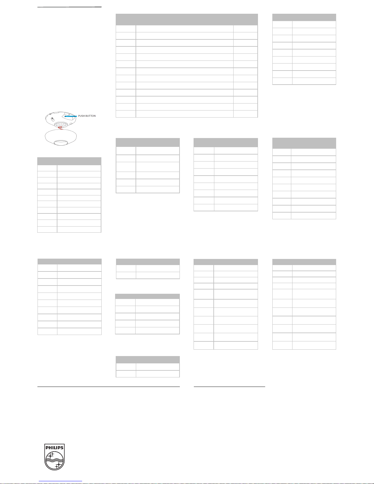
Programming
Please read all 3 steps before programming
1. Enter a programming function by pressing
button, on side of device, the number of
times as the desired function number from
the tables below (e.g., press twice for
function 2, occupancy time delay).
2. LED will flash back the selected function's
current setting (e.g., 5 flashes for 10 minute
time delay). To change setting, proceed to
step 3 before flash back sequence repeats 3
times. To exit the current function or to
change to a different function, wait for
sequence to repeat 3 times then return to
step 1.
3. Press button the number of times
indicated in the particular function's detailed
table for the NEW desired setting (e.g.,
press 3 times for 5 min). As confirmation of
setting change, LED flashes back the NEW
setting 3 times before exiting.
Function Description LRM2376
2 Occupancy Time Delay •
3 Dim to Off Time Delay •
4 Test Mode & 100 hr Burn-In •
4 Auto Set-Point •
5 Ten’s Digit of Set-Point •
6 One’s Digit of Set-Point •
7 Sunlight Discount Factor •
8 Incremental Set-Point Adjustment •
10 Minimum On Time •
11 Photocell Mode •
14 Lamp Information
15 Dimming Range (High) •
16 Dimming Range (Low) •
Programming Functons 2 Occupancy Time Delay
Selection Time
1 30 sec
2 2.5 min
3 5 min
4 7.5 min*
5 10 min
6 12.5 min
7 15 min
8 17.5 min
9 20 min
* default setting
Selection Operation
1 Normal*
2 Run 100 hr Burn-In
3
Run 100 hr Burn-In then
Auto Set-Point
4 Run Auto Set-Point
5 Blink back Set-Point
2
6 Test Mode
3
4 Test Mode / 100 hr Burn-In / Auto
Set-Point
2
The LED will blink back the ten’s digit,
then pause, then blink back the one’s digit.
For a “0” the LED will blink very rapidly.
The sequence is repeated three times.
3
Test Mode will disable Minimum On Time,
set Occupancy Time Delay to 30 sec. Mode
will expire after 10 min or if function 4 is
set back to Normal.
* default setting
5 Ten’s Digit of Holdback Set-Point
Selection Light Level (foot-candles)
1 10 fc
2 20 fc
3 30 fc
4 40 fc
5 50 fc
6 100 fc
7 200 fc
8 Disable
10 0 fc*
* default setting
6 One’s Digit of Holdback Set-Point
Selection Light Level (foot-candles)
1 1 fc
2 2 fc
3 3 fc
4 4 fc
5 5 fc*
6 6 fc
7 7 fc
8 8 fc
9 9 fc
10 0 fc
* default setting
8 Incremental Holdback Set-Point
Adjustment
Selection Change (foot-candles)
1 Decrease 1 fc
2 Increase 1 fc
The Philips OccuSwitch products, when properly installed and under normal conditions of use (without
overload, abuse or alteration), is warranted to you, the original user, for a period of two (2) years from the
date of original purchase, to be free from defects in materials and workmanship. If during the warranty period
you believe the purchased product or any part thereof has such a defect, you must return the product (or
part) at your cost during such period, with proof of purchase (or if installed by a third party a written
explanation of installation transaction with proof of date), to Philips Lighting Electronics N.A (1-800-3723331 / www.philips.com/advance), for repair or replacement (or to an authorized Philips Lighting Electronics
N.A. supplier which agrees in advance to handle the return and replacement by factory authorization). If the
product or part is found by Philips to have been defective in material or workmanship it will be repaired or
replaced (as deemed necessary by Philips Lighting Electronics N.A.), and the replacement will be returned to
you free of charge. The original user is solely responsible for any costs associated with removal and re-
installation of the product and shipping to Philips Lighting Electronics N.A. or its authorized supplier.
Warranty Statement Contact Information
©2012 Philips Lighting Electronics North America.
A Division of Philips Electronics North America Corporation.
All rights reserved.
Printed in the USA
Published 6/12
Part No. 12NC 4435 290 60691
Version 1
Philips Lighting
10275 West Higgins Road
Rosemont, IL 60018
Customer Care/Technical Service: 800-372-3331
Email: [email protected]
Website: www.philips.com
Selection Voltage (Volts)
1 Off
2 1
3 2
4 3
5 4
6 5
7 6
8 7
9 8
10 9
11 10*
15 Dimming Range (High)
Selection Voltage
1 30 sec
2 2.5 min*
3 5.0 min
4 7.5 min
5 10.0 min
6 12.5 min
7 15.0 min
8 17.5 min
9 20.0 min
10 0 sec
11 Infinite
3 Dim to Off Time Delay
* default setting
16 Dimming Range (Low)
Selection Voltage (Volts)
1 Off
2 1*
3 2
4 3
5 4
6 5
7 6
8 7
9 8
10 9
11 10
* default setting
* default setting
7 Sunlight Discount Factor
Selection Factor
1 x/1
2 x/2
3 x/3
4 x/4*
5 x/5
6 x/6
7 x/7
8 x/8
9 x/9
10 x/10
* default setting
11 Photocell Mode
Selection Mode
1 Normal*
2 Dim Only (No Off)
* default setting
10 Minimum On Time
Selection Time
1 0 min
2 15 min*
3 30 min
5 60 min
4 45 min
* default setting
 Loading...