

Installation Guide
OccuSwitch Wireless Sensor
LRM176000
Occupancy sensor
with Daylight sensor
LRM174300
Occupancy sensor
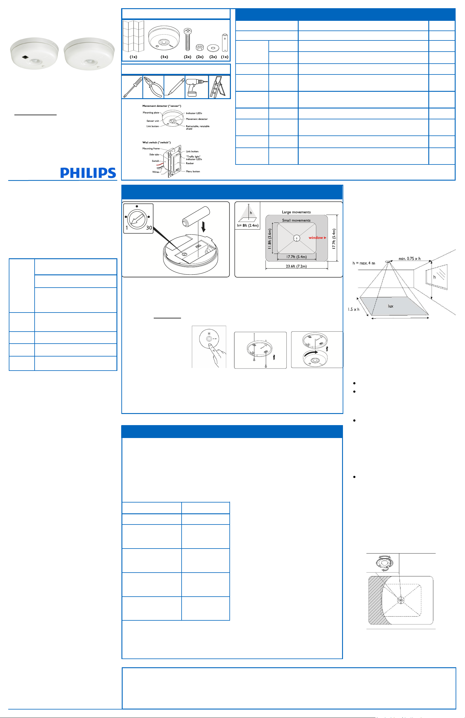
Sensor box contents
Tools required (for entire install)
LEDs and Buttons
Indication Meaning Device
Red, Ye llow , Gr een Device starts up or reset to factory defaults All
10 sec. A device asked to show all linked devices All
Gr e en
Ye llo w Bl ink Irregular Sensor is showing coverage Sensor
Ye llo w Bl ink
Red Blink Regular
1 min. Device is in linking mode
Every 2
Sec.
Device is in the configuration menu
A linked device is missing
(see Troubleshooting)
Switch
Dimmer
Switch
Dimmer
Switch
Dimmer
Installation Steps
1. Install wall device (separate instructions)
2. Install sensor
3. Link devices
4. Configure, test and finish
Product Description
OccuSwitch™ Wireless automatically controls the lights
based on occupancy and daylight. The system has two
parts: ceiling-mounted sensor and wall mount power
handling device (switch or dimmer). The switch will turn
the lights On and Off based on the information received
from the wireless occupancy sensor. The dimmer will
dim lights Up and Down to the appropriate intensity
base on the available daylight in the space. The dimmer
can also manually dim the lights.
Key figures
Coverage is dependent on ceiling
height up to 12ft (3.65m).
Sensor
Coverage
Area
Wireless
Range
Network
Size
Light
Range
Dimen-
sions -
For a typical height of 8ft (2.4m):
Large motion 17.7 x 23.6ft (5.40m x 7.20m)
Small motion 11.8 x 17.7ft (3.60m x 5.40m)
Larger areas will require multiple sensors.
Wall device to sensor: 50ft (17m)
16 Sensors, Switches & Dimmers.
1 to 150 F.C. 10 to 150 LUX
3.3 x 0.98 in (84 x 25mm) (diameter x
height)
SAFETY
Parts of the switch & dimmer carry line power, which is a potential lethal voltage. This product was designed and manufactured
to ensure maximum safety during operation and service. Always
read these safety instructions before installing, maintaining or
servicing the product, and strictly comply with these instructions.
General
- If you are unsure about any part of these installation instruc-
tions, consult a qualified electrician.
- The devices are designed for indoor use only.
- To avoid short circuits, do not expose this product to rain or
condensing moisture. Short circuit may cause fire or electric
shock hazard. Operate the devices between 41°F and 104°F (5°
C and 40°C) ambient temperature. .
- Use only a soft damp cloth to clean, never use any abrasive or
chemical cleaner.
- Whenever it is suspected that an unsafe condition exists, switch
off power at the circuit breaker and replace the device. Safety
is likely to be impaired if, for example, the equipment fails to
perform the intended functions or if the equipment shows
visible damage. Do not paint the devices.
Wall Device (Switch & Dimmer) only
- Disconnect power at circuit breaker or fuse when servicing,
installing or removing the fixture of the switch.
- Only use with copper or copper clad wire.
- Wire switch to the line power according to the wiring scheme in
this manual.
Sensor only
- The sensor cannot control loads directly use compatible switch
or dimmer.
- Use only high-quality AA size, 3.6V Lithium-thionyl chloride
batteries sensors. Using improperly rated batteries may damage the sensor or fail to operate properly.
- Dispose of used batteries promptly. Keep batteries away from
children, do not disassemble and do not dispose of in fire.
WARNING: The product is intended to control lighting loads
only. Do NOT use to control equipment that could create hazardous situations, like entrapment. For examples, do NOT install
this product to control motorized gates, garage doors, industrial
doors, microwave ovens, heating devices, etc.
WARNING: It is the installer’s responsibility to ensure that
the equipment being controlled is visible from every control
location and that only suitable equipment is connected to these
controls. Failure to do so could result in serious injury or death.
CAUTION: The battery used with the sensor device may
present a risk of fire or chemical burn if mistreated. Do not recharge, disassemble, heat above 100°C, or incinerate. Replace
battery with Lithium-thionyl chloride (AA 3.6V) only.
Use of another battery may present a risk of fire or explosion.
2 INSTALL SENSOR
1 Set dial on back of sensor to 1 Minute time delay
for testing (optional).
2 Install battery - make sure you match polarity
3 Link Sensors to Switches / Dimmers before
mounting to simplify installation.
GO TO Sep 3 LINK DEVICES NOW
4 Choose the best location on the ceiling to mount
sensor. The sensor needs to cover the occupied
area. If the area is too large, more sensors can
be added and linked to the same switches and
dimmers.
3 LINK DEVICES
Note: After wall device is installed and power is re-
turned, test all wall devices by pressing the rocker
switch ON/OFF. All switches/dimmers should control
connected loads. If they do not control the lights
check wiring.
Create a Network: To create a wireless net-
work by combination of up to 16 switches, dimmers
and sensors take the following steps.
HINT: to prevent cross-linking rooms only one person
should do the links.
ACTION RESULTS
Test On/Off and set to Off Lights turn off.
1. Briefly press the LINK
button (Top of switch/
dimmer) for linking mode.
2. Briefly press the LINK
button on the sensor to add
it to the network.
3. Briefly press the LINK
button on additional devices
to add to network.
4. Briefly press the LINK
button on first switch/
dimmer again to exit.
Return to Step 2 to mount sensor.
Gre en LED on the
switch/dimmer starts
bl inki ng.
Lights turn On and
sensor’s green L ED
tu rns on .
Green L ED on each
device turns On to
confirm link.
Gre en LED on the
switch/dimmer stops
blinking.
Red Blink 2 Sec. rate Device is in the Action menu All
St eady Ye llow
Red Blink 5 Sec Rate Sensor Battery Low
Red Blink
Always ON
2 Sec.
Rate
Lights are switched manually. Automatic mode returns after
vacancy timeout or command to return to auto mode
During link test = low battery Sensor
Multi-Sensor Placement
The Multi sensor with its photocell needs to see a
representative area of the space not just the desk. If it
is closer to the window, it dims more aggressively. If it
is on the other side of the light fixture it will dim less.
It is more important how far the sensor is from the
window then if it is over the desk.
Sensor mounting Plate
The sensor mounting plate can be attached to the
ceiling tile using the supplied hardware. For other
ceiling materials use appropriate hardware to secure
permanently. After the mounting plate is installed the
sensor by inserting into the mounting plate and turning clock wise to secure it.
Sensor placement guidelines
5 Before mounting sensor check time delay dial
(common setting is 10 to 15 minutes).
6 Attach sensor to mounting plate.
7 Test coverage pattern
8 Add enhance features and daylight configura-
tion , see back of this sheet
Troubleshooting
See LEDs and buttons description.
When linking, if Red LE D on the sensor turns On ,
then linking failed. Try again and move the sensor
closer to the switch, (within 50ft.)
When linking, if Red LE D on the sensor starts to
bl ink, you pressed and held the LINK button too
long. The sensor entered the ACTION menu. Press
and hold the link button to exit.
Warning: If the green LED starts blinking on another
switch/dimmer, that switch/dimmer is now also in
linking mode, starting its own network. Press the
LINK button on that switch/dimmer and try the
whole procedure again. If the problem persists, the
distance between the new switch/dimmer and the
existing switch may be too large (see Key figures).
Note: If the yello w LED is turned ON after linking, the
switch/dimmer is in manual override. After the sensor
timer has expired, it will return to automatic mode and
the LED will go off. Or, hold down the ON rocker until
the yellow LED goes out, returning to auto mode.
RESET to factory default settings - If the links or set-up
are not correct they can be cleared in each device by
holding down the LINK/ACTION Button for about 10
seconds. Release when LED’s briefly blink all together.
After releasing they step from RED - YELLOW - GREEN.
The sensor should be mounted in such a way that:
Small movements are detected for the space
Large movements are detected for the entire
room, and in particular for the area near the
doorway. Motion from adjacent areas, e.g. the
hallway, is not detected.
The center of a room is usually not a good location. Moving the sensor towards the wall where
the door is located, but not seeing out the doorway, may still cover the entire room, while blocking unwanted detection of motion from the
hallway. If needed, pull out the sensor shield
(indicated on the ring with a dot), and rotate it to
the required direction.
The sensor should not be placed close to heat
sources (especially incandescent lamps) or HVAC
exhausts.
Coverage pattern shield - If needed pull out the sensor
shield and rotate to avoid unwanted motion detection.
Switch
Dimmer
Switch
Dimmer
FCC COMPLIANCE STATEMENT
This device complies with part 15 of the FCC rules. Operation is subject
to the following two conditions: (1) This device may not cause harmful
interference, and (2) this device must accept any interference received,
including interference that may cause undesired operation. Any changes
or modifications not expressly approved by Philips could void the user’s
authority to operate this equipment. This product is intended for commercial use only.
Copyright NOTICE
All referenced brands, product names, service
names and trademarks are the property of their
respective owners.
Copyright 2011 Koninklijke Philips Electronics N.V.
TECHNICAL SUPPORT
For technical support on this product contact:
Philips Lighting Electronics N.A.
10275 W. Higgins Road
Rosemont IL 60018
Customer Care: 1-800-372-3331
tech.service.rosemont@philips.com
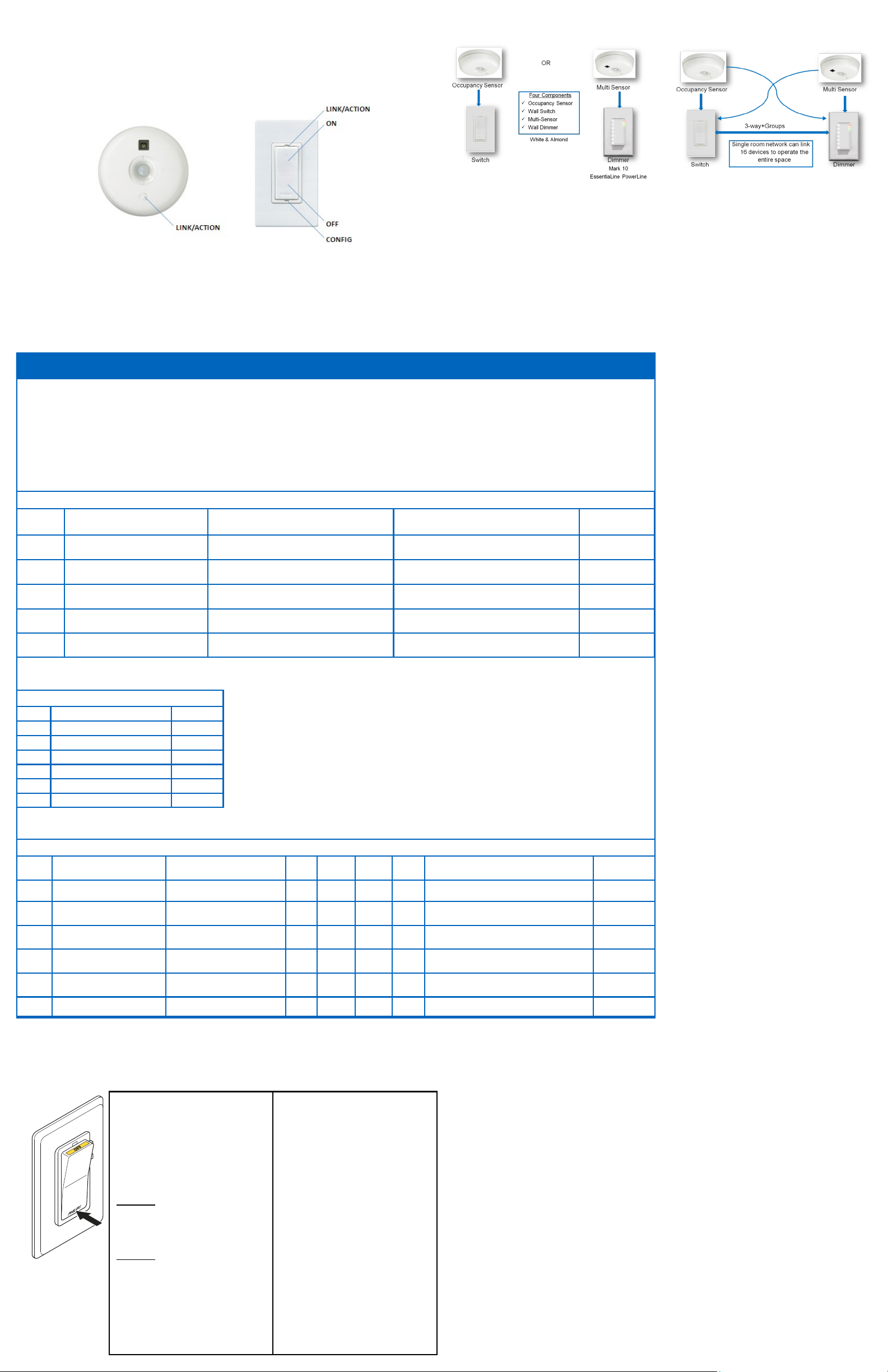
Configuration and set-up
After successfully installing and linking the sensors and
wall devices you can change settings to customize the
system to the needs of the user.
One to One SET-UP Combined Device SET-UP
SET-UP hint
Use a small screw drive or similar device to push the
Menu buttons.
Short button press : < 1 second
Long button press: > 2 seconds
To dim up, press and hold the ON button
To dim down , press and hold the OFF button
Menu operations use CONFIG and LINK/ACTION but-
tons as described in the Configuration (YELLOW) and
Action/RED menus below.
LED response Signals
Spike - Very short blinks
Blink - LED switching On and Off
Manual Mode - Manual mode is entered when the
rock switch is pressed and the Yellow LED comes On.
After sensors are linked, the system will return to auto
mode when the room if vacant and the delay timer
expire. To return to Auto Mode Hold down the On
rocker until the Yellow LED goes out.
4 CONFIGURE, TEST & FINISH
Configure
When all sensors and wall devices are linked, you can
change the operation settings. This is done at any wall
device; the settings are automatically sent to the other
devices in the rooms network. You can select the following options in the Configuration and Action menus.
Test sensor coverage
Once all devices are installed, linked and configured,
you can test the installation to ensure that:
The sensor detects motion in the workspace. Test to
make sure sensor does not pick up motion from adjacent areas, e.g. the hallway. This can be done at anytime, see ACTION Menu for steps.
CONFIGURATION (Yellow) Menu for both Wall Devices - Press CONFIG button (Long to enter) (Short for next item)
Item Description Action
Start Yellow Spike (…/…) Exist Long Press CONFIG to exit N/A
1 Yellow Blinks (…1…) Manual ON/ Auto OFF (Title 24)
2 Yellow Blinks (…1..1…) Multi-Way Configuration Long CONFIG to create multi-way group Long CONFIG
3 Yellow Blinks (…1..1..1…)
4 Yellow Blinks (…1..1..1..1…)
Dimmer Response Curve
Blink - Top LED
1
Blink - 2nd LED
2
Blink - 3rd LED
3
Blink - 4th LED (default)
4
Blink - 5th LED
5
Blink - 6th LED
6
Blink - Bottom LED
7
Straight Line
Dimmer Response Curve
(Dimmer Only)
Set High End Level (Task Tuning)
(Dimmer Only)
(Config #3)
-50%
-20%
-10%
+10%
+20%
+50%
Dimmer Response Curve - If
the Daylight dimming response
is too aggressive the Dimmer
can be set to respond less to
daylight. If the response is too
low the dimmer can be set to
react more to additional daylight.
Long CONFIG = Manual ON
Long ACTION = Auto ON
Long CONFIG to change response curve Long CONFIG
Long CONFIG = Sets maximum dim level
Long ACTION = Return to 100%
ACTION (Red) Menu for Sensors and Wall Devices- Press LINK/ACTION button (Long to enter) (Short for next item)
Item Indicator Description
Start Red Spike (…/…) Exit X X X X Long LINK/ACTION to exit
1 Red Blinks (…1…) Show Linked Device X X X X Long LINK/ACTION to start
2 Red Blinks (…1..1…) Test Sensor Coverage X X X X
3 Red Blinks (…1..1..1…)
4 Red Blinks (…1..1..1..1…) Daylight Hold Back X N/A X X Long LINK/ACTION to Start
Calibrate Daylight dimming
set-point (< 1 min. process)
Wall
Switch
Wall
Dimmer
N/A X X X Long LINK/ACTION to Start Automatic
Multi-
Sensor
Occ.
Sensor Action Results
Finish
OccuSwitch Sensors and Wall Devices do not need any
regular maintenance. You may find as people change
space and future is re-arranged that you need to recalibrate the daylight functions. This can easily be
done at floor level from the wall device.
Automatic
Automatic
Long LINK/ACTION to Start
Short LINK/ACTION on sensor to Finish
Store
Setting Indicator
Automatic
Automatic
SET-UP OPTIONS
For best result set each desirable option in the order
listed below.
(Config #1)
Manual ON / AUTO OFF (Title 24 mode) - This is
a popular setting for maximum energy savings. It force
the occupant to manual activate the lights when they
enter the space and automatically turn OFF the light
when they leave. This save energy by keep the lights
OFF until they are actually needed.
(Config #2)
Multi-Way Configuration - Several switches and
dimmers can be put in a group that control each others load when operated manually.
You can create several independent control groups
linked to the ceiling sensors.
1. Use CONFIG menu item 2 - All wall devices will
start to blink: GREEN is included, RED is excluded.
2. Tap the ON button to include, OFF bottom, to
exclude.
3. Long CONFIG button press will save the settings.
4. Repeat from step 1 on different wall devices to
form more groups.
(Config #4)
Set High End Level - If you want to limit the maxi-
mum output from a dimmer set the desired high end
level and run through Configuration Menu (Yellow) #4.
(Action #3)
Daylight Calibration (FIRST TIME) - Only one
sensor can be linked to one Switch (Hold-back) or one
Dimmer (continuous dimming) for Daylight Regulation.
The first time the daylight Action Menu is activate the
system unlocks and links the senor to the wall device
for Daylight regulation. This can be done from the floor
before mounting the sensor.
Next time - After the first activation and calibration
the daylight menu can be run from the wall device to
recalibrate the daylight settings.
Calibration process - When the sensor and the wall
device enter calibration mode the
Tip: It is important that the daylight is constant and is
not too bright (no need to calibrate in the dark).
1. Use dimmer to dim to the required light level
using light meter on the work surface.
2. Go into action menu on the sensor to select
Calibration daylight regulation set-point menu
item. (Yellow LED starts Blinking)
3. Clear the area under the light sensor (walk away).
4. Automatic Configuration will start in about a
minute. All dimmers in the system go to 100%,
then switch off. The green LED on the device
turns on. Sensor confirms new setpoint using
green LED. The system enters automatic light
regulation mode.
Note: This process can be repeated anytime after the
first time from the wall device without touching the
(Action #4)
Daylight Hold-Back - Similar to Daylight calibration
but results is to set the level at which the light will not
turn ON automatically (Hold-Back level)
5 Red Blinks (…1..1..1..1..1…) Channel Change X X X X Long LINK/ACTION to Start Automatic
Maintenance
Routine lamp replacement
To safely do a routine lamp replacement,
on all switches, firmly press the OFF-side
until the rocker clicks into the position
where a yellow band with “OFF” becomes
visible.
The load is now temporarily separated
from the line voltage by an air gap switch,
so you can safely replace the lamp.
WARNING: If the air gap function is not
used, the power may be switched ON
unintentionally by the sensor while replacing the lamp. This could result in serious
injury or death.
WARNING: For any procedure other
than lamp replacement, power must be
disconnected at the main electric panel.
Use approved LOCK-OUT/TAG-OUT procedures to insure that the circuit is not activated accidently. Working with power ON
is unsafe and can result in serious injury or
death.
Replacing the sensor battery
CAUTION: You must have read the
SAFETY section before replacing the
battery.
To replace the battery of the sensor:
1. Rotate the sensor counterclockwise
to remove from mounting plate.
2. In a safe and dry place, remove the
old battery and insert the new
battery.
CAUTION: Use only high-quality AA
size 3.6 V DC lithium-thionyl chloride batteries with the sensor.
Using improperly rated batteries
may damage the sensor.
3. Place the sensor back on the
mounting plate and rotate clockwise to fix it.
4. Dispose of used battery properly.
DO NOT throw in trash. Keep away
from children. Do not disassemble
and do not dispose of in fire.
Troubleshooting System
The lights turn off too quickly: The system has a
smart timer that adjust the off delay time automati-
cally. To change, set sensor’s minimum timeout dial to
a higher value.
The system is set to Manual ON, but lights turn on
automatically: When entering the area within 5 min-
utes after lights turning off, the system assumes that
turning off was undesired and turn ON the lights.
The system shows that a linked device is missing:
When a device is missing, use the ACTION #1 menu to
show all linked devices. If a sensor does not show as
linked, its battery may need to be replaced. If this does
not resolve the error, reset all devices and link them
again.
The lights immediately turn ON after being turned off
The sensor may be placed too close to a (heat generating) light source. Move the sensor to a better location.
Reset the device to factory defaults
To reset the device to its factory default configuration:
Press and hold the link button on the device for
more than 10 seconds. Release the button when the
re d, ye llow and gre en LED s light briefly.
(Action #5)
Channel Changing - In some building environments
the radio signal used for OccuSwitch Wireless may
encounter interference from another radio device.
Channel changing activate the system automatic radio
analysis function toe reset the channel. Use this function if you are having communications issues.
WARRANTY STATEMENT
The Philips OccuSwitch™ Wireless products, when properly
installed and under normal conditions of use (without overload, abuse or alteration), is warranted to you, the original
user, for a period of two (2) years from the date of original
purchase, to be free from defects in materials and workmanship. If during the warranty period you believe the purchased
product or any part thereof has such a defect, you must return
the product (or part) at your cost during such period, with
proof of purchase (or if installed by a third party a written
explanation of installation transaction with proof of date), to
Philips Lighting Electronics N.A (1-800-372-3331 /
www.philips.com/advance), for repair or replacement (or to an
authorized Philips Lighting Electronics N.A. supplier which
agrees in advance to handle the return and replacement by
factory authorization). If the product or part is found by Philips
to have been defective in material or workmanship it will be
repaired or replaced (as deemed necessary by Philips Lighting
Electronics N.A.), and the replacement will be returned to you
free of charge. The original user is solely responsible for any
costs associated with removal and re-installation of the product and shipping to Philips Lighting Electronics N.A. or its
authorized supplier.
 Loading...