

Page 1

LRM1070, LRM1080
Product guide
OccuSwitch movement
detector
Page 2
LRM1070, LRM1080
500 mm (19.69 in)
The OccuSwitch is a movement detector with a
build-in switch. It will switch o the lights in a room
or area when it is vacated and thus save up to 30% of
electrical energy. The OccuSwitch can switch any load
up to 6A and control an oce area of around 20m2.
A detachable mains connector enables easy
installation and mounting of the OccuSwitch in the
ceiling.
A separate Wieland cable is available for easy,
fast and trouble-free installation.
The OccuSwitch family exists of:
LRM1070 Basic OccuSwitch
LRM1080 Advanced OccuSwitch
LCC1070 Wieland cable
LRH1070 Ceiling mounting box
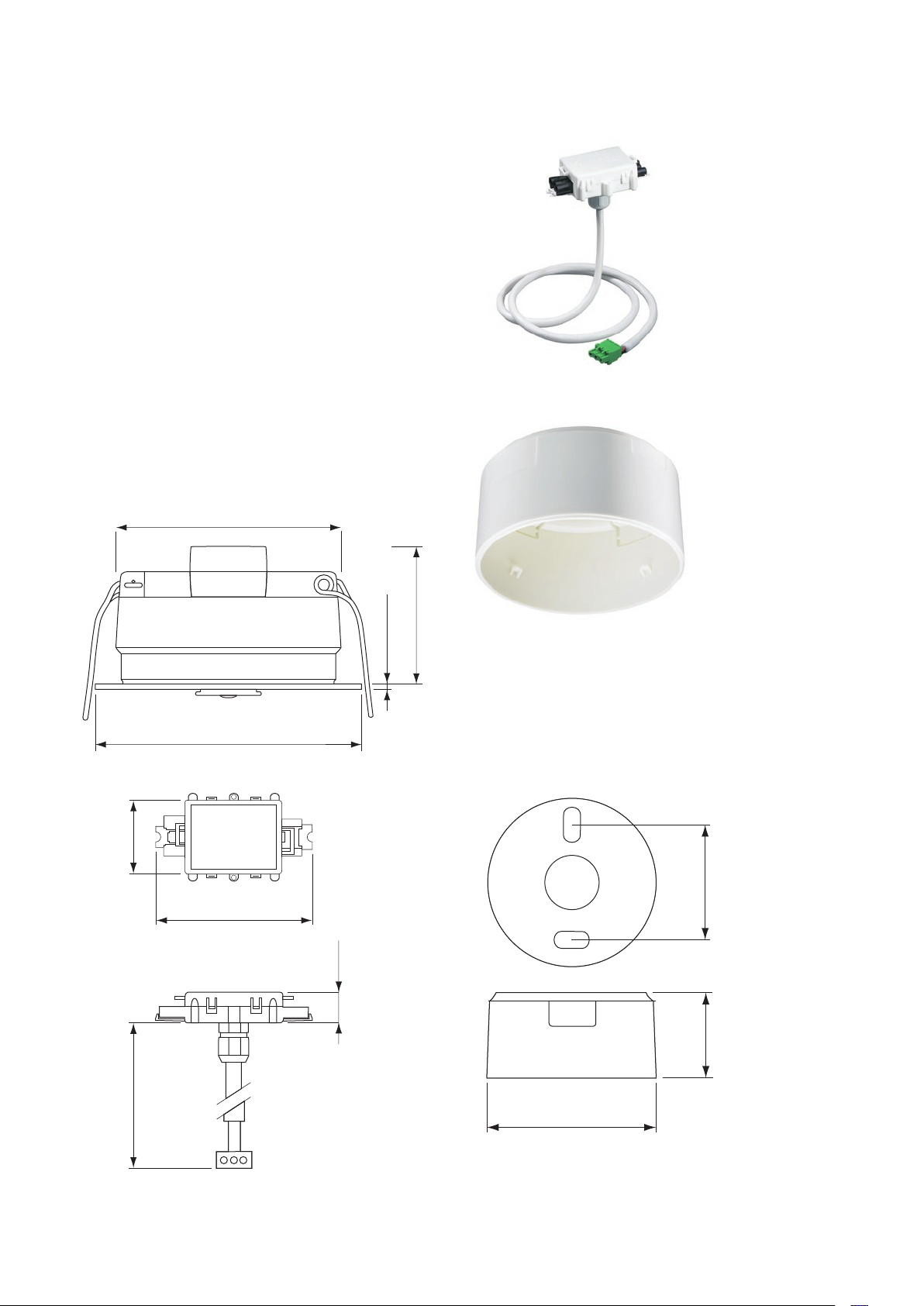
Dimensional drawing
Ø 80 mm (3.15 in)
LCC1070 Wieland cable
Ø 95 mm (3.74 in)
LRM1070 Bas ic OccuSwi tch, LRM1080 Advanced Occ uSwitch
(2.66 in)
67.5 mm
113.5 mm (4.47 in)
(1.04 in)
26.5 mm
50 mm (1.97 in)
2 mm (0.08 in)
LRH1070 Ceilin g mounti ng box
56 .. 66 mm
(2.20 .. 2.60 in)
(2.03 in)
51.5 mm
Ø 95 mm (3.74 in)
LRH1070 Ceilin g mounti ng box
LCC1070 Wieland cable
2 Produc t Guide - LRM1070, LRM1080
Page 3
Applications
The OccuSwitch is designed for use in oces and
similar applications, including toilets, storage rooms,
etc. It is optimized for recessed ceiling mounting and
for mounting heights between 2.5 and 3.5 meter.
The surface box allows surface-mounting as well, with
either recessed wiring or surface-mounted ducts.
The advanced OccuSwitch can be connected in
parallel (max 10) to cover larger area’s like open plan
oces. The use of dierent mains groups or even
phases is no problem.
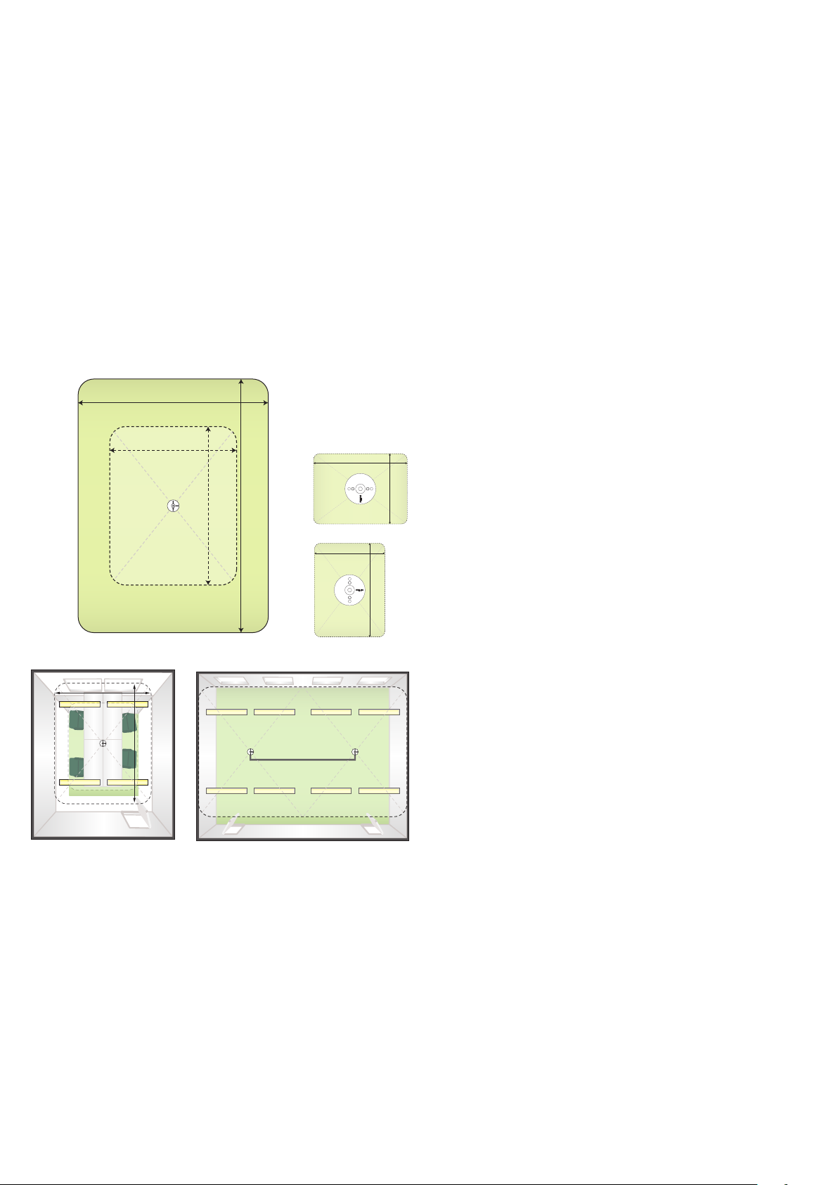
The OccuSwitch’s detection pattern (see drawing) is
4 by 5 meters for minor movements (desk work) and
6 by 8 meters for major movements like walking.
6m
4m
5m
4m
8m5m
4m
Daylight override
It is possible to prevent the automatic switch-on
when sucient daylight is available in order to create
additional savings.
Daylight switching
When daylight switching is active, the lights will
automatically be switched o when sucient daylight
becomes available, and turned back on when the light
level drops below the required level.
Functions advanced version
Parallel operation
It is possible to connect up to 10 OccuSwitches in
parallel via a separate bus signal. When one of the
OccuSwitches detects movement, all units will switch
the lights on. The bus signal is fully isolated, so each
OccuSwitch can be used on any mains group or
phase, allowing the use of several mains groups in an
area and easy wiring.
Local override
With a remote control it is possible to override the
automatic operation of the OccuSwitch, for instance
to switch lights o even if there is movement detected.
5m
Detection pattern Position OccuSwitch
4m
5m
Standard application Parallel operation
Functions (both versions)
Automatic control
The OccuSwitch switches the lights on automatically
when movement is detected and switches the lights
o after the area is vacated (after 1 to 30 minutes
depending on the settings).
Absence mode
When a remote control is used it is also possible to
disable the automatic switch-on when people enter
the area that the OccuSwitch is controlling.
Features (both versions)
Smart timer
The smart timer will extend the delay time by 10
minutes if movement is detected shortly after switcho, assuming that the area is still in use, but very little
movement is made.
Shield
The OccuSwitch has a retractable shield that can be
used to shield o areas like corridors, adjacent to the
area the OccuSwitch is controlling.
Features advanced version
Remote tool
With a remote control tool (IRT9090) it is possible to
change the light level settings without the need to
reach for the OccuSwitch itself.
Using the tool it is possible to change the power-up
setting from its default (switch-on). The OccuSwitch
will not switch on at power-up and will start detection
30 seconds later.
Produc t Guide - LRM1070, LRM1080 3
Page 4

Mounting
(2.03 in)
(2.20 .. 2.60 in)
4
5
22 x 10 mm
25 x 13 mm
25 x 16 mm
16 x 16 mm
LRH1070
LRM1070
LRM1080
Fixing
The OccuSwitch can be mounted in two ways;
recessed in the ceiling or surface-mounted using
the ceiling box.
The ceiling box (LRH1070) has breakout ports for
cable ducts and a breakout centrepiece.
When selecting a location for the OccuSwitch, avoid
obvious cold spots so that condensation does not
occur.
Fixing the OccuSwitch in a ceiling (recessed)
Fixing the OccuSwitch on a ceiling
(surface-mounted)
No. 8 (Ø 4 mm)
35
56 .. 66 mm
51.5 mm
Ø 95 mm (3.74 in)
1
2
80-82 mm
1
2
1
> 50 mm
≤ 30 mm
22 x 10 mm
25 x 13 mm
25 x 16 mm
16 x 16 mm
LRH1070
LRM1070
LRM1080
3
5
4
max. 185 mm
4 Product Guide - LRM1070, LRM1080
Page 5

Electrical Installation
Wieland cable (LCC1070)
The OccuSwitch can be installed with either
conventional wiring or Wieland connectors. For
the second option, the Wieland cable (LCC1070) is
required. The OccuSwitch comes with a detachable
mains connector for easy installation. This connector
is removed if the Wieland cable is used. The mains
connection is protected by a retractable cover and
secured with a tie wrap.
L
N
Ls L N
Installation (conventional wiring)
Parallel operation
Parallel operation is used to enlarge the covering area
of the OccuSwitch. This can be done in two ways;
either by parallel installation or by using the parallel
connection of the advanced OccuSwitch (LRM1080).
Parallel installation limits the total load to 6A and
restricts the application to one mains group. For
parallel connection the LRM1080 uses a bus signal to
indicate movement detection to other units. All units
can be used up to 6A each and with several mains
groups (or even phases). A short delay between the
dierent units during switch-o may occur. Max. 10
LRM1080 in parallel.
L
N
LsL N
LsL N
Installation (Wieland)
2
Parallel installation
L3
L2
L1
N
L
N
LsL LN
-+
click
1
4
3
+
Parallel connection (advanced only)
H05VV-F
5
Ls N
-+
D Note
The connector of the OccuSwitch is capable of
accepting a wide range of cables (1.5 to 2.5mm2),
but when heavy ridged cables (especially single
core) are used it is strongly advised to make use of
the LCC1070 to prevent the OccuSwitch of being
pushed out of the ceiling due to the weight of
these ridged cables.
Produc t Guide - LRM1070, LRM1080 5
Page 6

Commissioning
Daylight control
Daylight override
The daylight override function prevents the lights from
switching on when sucient daylight is available. To
enable this function it is necessary to set the required
light level by turning the dial counterclockwise (CCW)
away from the OFF position. To disable this function,
turn the dial clockwise (CW) into the OFF position.
Daylight switching
This function will actively switch the lights o if
sucient daylight is available.
To enable this function, the DIP switch for this
function has to be set to the ON position and the light
level must be set (see daylight override).
When this function is enabled, lights will switch o
when the light level is above 220% for more than 15
minutes.
When switching o, the available daylight reaches at
least 120% of the required light level. The lights will
switch on again when the light level drops below the
required level.
= o
-
ON
1 2
on
+
ON
Calibration
Turn the dial to raise or lower the required light level.
+
-
Calibration
Local control (LRM1080)
The OccuSwitch LRM1080 (advanced version) will
react to commands given by a suitable Philips remote
control. There is no special setting required. Although
the OccuSwitch will operate with all remotes capable
of sending the right codes, the IRT8050 (wallmounted) is best suited for this application.
The OccuSwitch will respond to channel 1 codes (on/
o). By default it will respond to group A and general
codes.
Only with the IRT9090 is it possible to change the
group address to make a distinction between dierent
OccuSwitches and remote controls. The OccuSwitch
does not react to preset commands.
The remote control should be operated within the
detection area of the OccuSwitch.
1 2
o
Enabling daylight override and switchin g
D Note
This function can only work correctly if the
required light level is the same as the installed
light level. The OccuSwitch will automatically raise
the switch-o level if the required light level is set
well below the installed light level (for instance
500 Lux required with 1000 Lux installed). This
IRT8050
Absence mode
The OccuSwitch will not switch on the lights
automatically in absence mode. A remote control
must be used to switch on the lights. The OccuSwitch
will switch o after 1 to 30 minutes after the area is
vacated. Set the DIP switch in the right position to
activate the absence mode.
will prevent the lights from switching on and o in
a 15 minute cycle.
The OccuSwitch can switch o once or twice (with
a 15 minute delay) for reference purposes. This
cycle will repeat every time the OccuSwitch is
reconnected to the mains power.
Enabling absence mode
6 Product Guide - LRM1070, LRM1080
ON
1 2
ON
1 2
Auto on
IR on
Page 7

IRT9090 (LRM1080)
Set required light level
Make certain that the required light level is available
and no daylight is entering the area.
Calibrate by aiming the IRT9090 towards the
OccuSwitch and pressing the “save” button.
The lights will ash once to indicate the new level is
stored.
I/II
PLBMS W/C
21 3
20% B10% AII30% C
54 6
50% E40% D 60% F
87 9
70% G
o
on
0
min
group
save
cong
mode
)))
O
test
link? mode?
add
zone
on/o
A-G
%
power up background IR group reset
pirdelay daylight RF channel
scene
IRT9090 Calibrate light level
Luxmeter
100 h
0
= 1x
Change IR group
Both the OccuSwitch and remote controls can operate
in 7 dierent groups. Both the remote controls and
OccuSwitch must be in the same group.
Select the “IR group” button on the IRT9090, followed
by the desired IR group (A-G, buttons 1 to 7).
Aim the IRT9090 towards the OccuSwitch and press
the green “send” button. The lights will ash once to
indicate the new setting is stored.
Change power-up behaviour
The OccuSwitch switches the output on when it is
connected to the mains. If the area is vacated the
lights will switch o after 5 minutes.
It is possible to leave the output o and start
movement detection 30 seconds after the mains is
connected.
On the IRT9090 select the “power up” button,
followed by either “on” or “o”. Aim the IRT9090
towards the OccuSwitch and press the green “send”
button. The lights will ash once to indicate the new
setting is stored.
Restore defaults
To restore the default settings, aim the IRT9090
towards the OccuSwitch and press the “reset” button.
D Note
The IRT9090 will send the power on and IR group
settings together (if changed). To erase previous
settings press “reset” followed by “send” on the
IRT9090.
B Warnings
The OccuSwitch should not be used in the
following situations:
• In applications outside the specication range,
most notable heights above 3,5 meter.
• Environmental conditions other than in a normal
oce environment (temperature, humidity).
• In applications with heat sources like electrical
heaters, within the detection range of the
OccuSwitch.
• In combination with lighting sources, or other
devices, that can be damaged if they are
switched o and on in a short period of time.
B Warnings advanced version
The OccuSwitch should not be used in the
following situations
• In applications with (semi-continuous)
Max. 17m
IR appliances like IRDA communication,
IR communication between PDA and phones
= 1x
and other devices, headsets operating
with IR communication, etc. Please note
that some devices with IR communication
send IR messages, even when there is no
communication link. These features must be
Send command
disabled.
• In applications with electronic ballasts that
operate up to or near the IR transmission
frequency of 36Khz. Also when these
ballasts are not used in combination with the
OccuSwitch, but the light from the lamps they
operate is visible to the IR receiver.
Produc t Guide - LRM1070, LRM1080 7
Page 8

Specications
Mains connection
Voltage 230VAC +/1 0%; 50/6 0Hz
Maximum load 6 A. (1380 VA) any load
Connector screw
terminal
Maximum wire range 1.5 to 2.5mm
Mains distribution
system
Power consumption
Stand-by 1.2 W
Max. 1.2 W
MRT3P7.62-3VE or
GMVSTBW2.5/3-ST-7.62
2
TN-S, 16A max, with
Neutral grounded
Environmental
Temperature +5 to +50°C (op erating)
-20 to +70°C (storage and
transport)
Settings
LED indicator Red on movement
detection
Switch o delay 1 to 30 minutes
Light levels 250 to 1000 Lux
(30% reection)
Detection range see diagram
The remote control and
light sensor work in a
similar range.
Compliances and approvals
Standards EN/IEC 60669-2-1
Electronic switches
Classication Class I
Pollution degree 2
Over voltage category III
Relative humidity 20% to 90% (no
condensation)
Parallel interface
Maximum 10 units in parallel
SELV signal, max 5 V.
Free Topology Wiring
Polarity sensitive
Connector type screw terminal
CPF5.08-2VE or
MSTB2.5/2-ST-5.08
Maximum wire range 1.5 to 2.5mm
Maximum length 100m
2
Approbation Product complies with
the relevant European
Directive (CE)
KEMA
EMC
Compliance IEC (EN) 60669-2-1
Immunity IEC (EN) 61547
Emission IEC (EN) 55015 and IEC
(EN) 55022, class B
Housing
Protection Class IP20
Flammability UL94 V-0
Glow wire test 960°C/5s.
Insulation Double
insulation
(4kV) between Mains
and SELV
Weight 0.2 Kg
8 Product Guide - LRM1070, LRM1080
Page 9

Data
Packing data
Type Box dimensions
(mm)
LRM1070 Unit box 105 x 95 x 58 1 cardboard 0.12
LRM1070 Outer box 400 x 300 x 300 42 cardboard 5
LRM1080 Unit box 105 x 95 x 58 1 cardboard 0.12
LRM1080 Outer box 400 x 300 x 300 42 cardboard 5
LRH1070 Unit box 105 x 95 x 58 1 cardboard 0.044
LRH1070 Outer box 400 x 300 x 300 42 cardboard 1.8
LCC1070 Unit box 90 x 90 x 90 1 plastic bag 0.13
LCC1070 Outer box 289 x 214 x 178 18 cardboard 2.4
Ordering Data
Type MOQ Ordering number EAN code
Qty Material Weight (Kg)
net gros
EAN code
level 1
level 3
0.15
5.6
0.15
5.6
0.07
2.4
0.17
2.7
EOC
LRM1070/00 OccuSwitch basic 1 9137 003 27803 8711559 731384 8711559 731391 731384 99
LRM1080/00 OccuSwitch advanced 1 9137 003 27903 8711559 731407 8711559 731414 731407 99
LRH1070/00 Ceiling box 1 9137 003 28003 8711559 731438 8711559 731421 731438 99
LCC1070/00 Wieland cable 3p 1 9137 003 30303 8711559 731773 8711559 731780 731773 99
Produc t Guide - LRM1070, LRM1080 9
Page 10

© 2015-2016 Philips Lighting Holding B.V., all rights
reserved.
Specications are subject to change without notice.
Trademarks are the property of Philips Lighting Holding
B.V. or their respective owners.
3222 636 33176 6 October 2016
www.philips.com/controls
 Loading...