How it Works
Log In / Sign Up
Buy Points
How it Works
FAQ
Contact Us
Questions and Suggestions
Users
Philips
Loading...
L
LR6PC12A-27
LR6PC12C
17
LR6PC12C/10
LR6PC12C/27
2
LR6PC20C
LR6PC20X
LR6PC20X/27
LR6PC24C
LR6PC24C-27
2
LR6PC32A-27
LR6PC32C
19
LR6PC32C/10
LR6PC32C/27
2
LR6PC50A/93
LR6PS12C
LR6PS12C/27
LR6PS12X
LR6PS12X/93
LR6PS16A
16
LR6PS16A-27
LR6PS16C
17
LR6PS32A
19
LR6PS32A-27
LR6PS32C
18
LR6PS32C/10
LR6PS48C
18
LR6PX20A
20
LR6PX20C
17
LR6PX20C/10
2
LR754P10B/10
LRA1720
LRA1721
LRC1015
LRC1025
LRC1035
LRC2410
LRC5059
LRC5141
LRC5142
LRC5143
LRC5414-00
LRC5423
LRC5913
LRC5914
LRC5923
LRC5924
LRC5933
LRC5934
LRC5944
LRD1730
LRD 6199SWS
LRI1653-00
LRI1667
LRL1220
LRL5002
LRM1070
2
LRM1080
2
LRM1742
LRM1743
LRM1760
LRM1766
LRM207x
LRM208x
LRM209x
LRM226500
LRM2310
LRM2315
LRM2320
LRM2325
LRM2376
LRM 8112
LRM8115
LRM 8116
2
LSB-13
LSBS1
LSBS1/00
3
LSBS3700
5
LSBS3700-00
2
LSBS5000
LSBS5000/00
3
LSBS8000
2
LSBS8000/00S
4
LSBS900
3
LSBS900/00S
LSBS900S
LSBS900S99
2
LTC 0140
LTC 0142
LTC 0143
LTC 0240
LTC 0242
LTC 0243
LTC 0330/x1 Series
LTC 0435
LTC 0455
2
LTC 0725
LTC 0729
LTC 0809 Series AutoDome
LTC 0825
LTC 0829
Loading...
Loading...
Nothing found
LRD1730
User Manual
2 pgs
1.02 Mb
0
Table of contents
Loading...
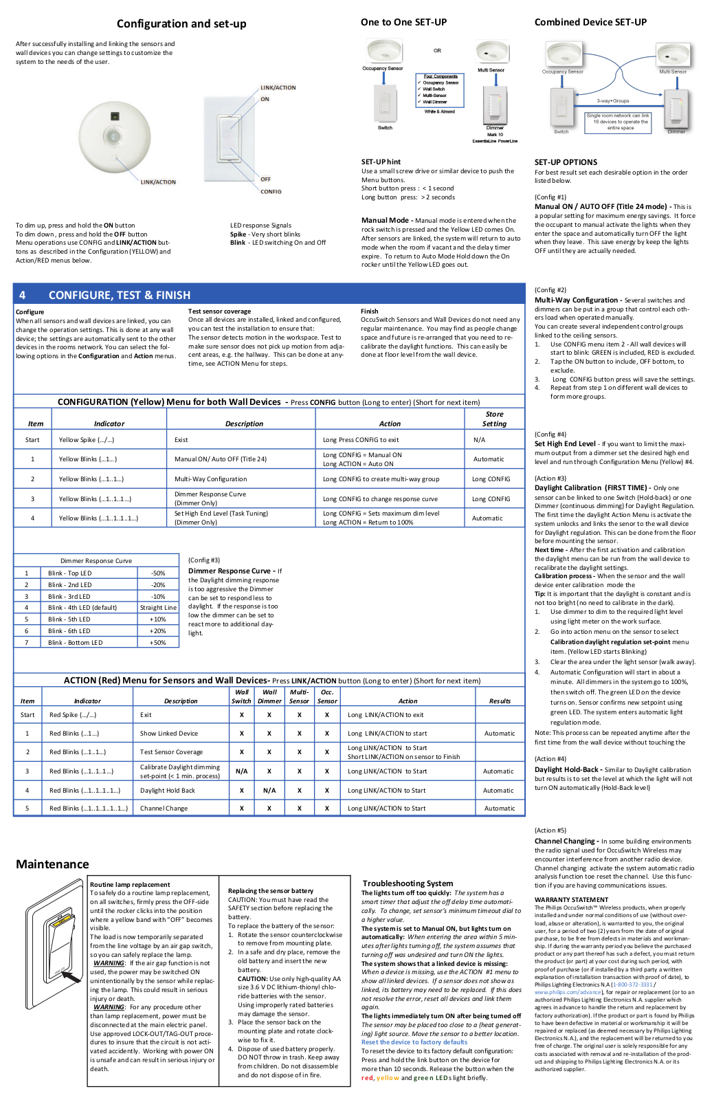
Philips LRD1730, LRA1721 User Manual
...
Philips User Manual
Download
Specifications and Main Features
Frequently Asked Questions
User Manual
Download
Loading...
+
hidden pages
Unhide
You need points to download manuals.
1 point = 1 manual.
You can buy points or you can get point for every manual you upload.
Buy points
Upload your manuals
 Loading...