

Page 1
PHILIPS
21XLP -2 Light Probe
for Brilliance 201CS monitor with Cyberscreen ® technology
Page 2

21XLP -2
Light Probe for Brilliance 201CS monitor with
Cyberscreen ® technology
User‘s Guide
First edition - November 1996
This guide has been made of recycled paper, to help protect the environment.
Page 3

IMPORTANT NOTICE
Because of a continuous product improvement poiicy, information in this guide and the
software furnished with it are subject to change without notice.
PHiLiPS Eiectronics N.V. shail not be iiable for any technicai or editoriai error contained
herein, nor for direct, indirect or consequentiai damages resulting from any defect in the
software or in its documentation.
This guide contains information protected by copyright.
No part of this document may be reproduced or copied, in whole or in part, or transiated into
other languages without prior written consent of PHILIPS Electronics N.V.
PHILIPS Electronics N.V. grants the license to install and use the software furnished with this
manuai on any computer owned by you. You are allowed to make up to two (2) copies of the
magnetic media for archiving purposes but you may not dupiicate the written documenta
tion.
You may not decompiie, disassembie, modify, adapt or create derivative works based on this
software for distribution on third parties.
TRADEMARKS ACKNOWLEDGMENT
Cyberscreen ® monitor is a Philips technology.
Brilliance is a registered trademark of PHILIPS Electronics N.V.
IBM PC is a registered trademark of International Business Machines Corp..
Microsoft is a trademark and Windows is a registered trademark of Microsoft Corporation.
Apple and Macintosh are trademark of Apple Computer Inc.
Other brands or product names used herein are for identification purposes only and may be
trademarks and/or registered trademarks of their respective holders.
RADIO INTERFERENCE WARNING
The 21XLP -2 Light Probe has been tested and found to comply with the limits for a class A
digital device, pursuant to Part 15 of the FCC Rules. These limits are designed to provide
reasonable protection against harmful interference when the equipment is operated in a
commercial environment.
This equipment generates, uses and may radiate radio frequency energy and, if not installed
and used in accordance with the instruction manual, may cause harmful interference to radio
communications.
Operation of this equipment in a residential area is likely to cause harmful interference in
which case the user is required to correct the interference at his own expense.
Page 4

Printing History
The firmware release printed after the date indicates the version level of the Light
Probe software at the time the manual was issued.
Edition 1, November 1996 Light Probe software release 3.0
Since many software updates do not require manual changes and viceversa, do
not expect a one-to-one correspondence between software releases and manual
editions.
Conventions
The following international conventions may appear in this manual:
NOTE: Calls attention to a procedure, condition or practice that requires special
attention by the reader.__________________________________________________
CAllTiON: calls attention to a procedure, condition or practice that could possibly
cause damage to equipment or permanent loss of data.
___________________________
WArnINC: calls attention to a procedure, condition or practice that could
possibly cause body injury or death.
______________________________________
Typographical Conventions
This font type indicates a menu command name, a file or directory name or
text that system or software displays on the screen.
Ill
Page 5

Preface
Thank you for purchasing the 21XLP -2 Light Probe for Briliance 201CS monitor with
Cyberscreen ® technology. We hope you will enjoy using it and we are confident that
this quality product will meet your highest expectations.
This user guide tells you how to install and operate the 21XLP -2 Light Probe packa
ge. Here is how the manual is organized:
Chapter 1 gives an overview of the Brilliance 201 CS technology and a brief intro
duction of the 21XLP -2 Light Probe.
Chapter 2 lists all the components of the 21 XLP -2 package, the system require
ments for its correct operation and how to install both hardware and software parts.
In Chapters 3, 4 & 5 you can find, respectively, a detailed description on how your
Brilliance 201 CS can be calibrated in terms of white balance, white uniformity and
convergence.
Chapter 6 gives you direction for cleaning and maintenance of the product.
Appendix A, What’s behind, introduces you to the theory of color perception and
describes how your monitor can display color images.
It briefly explains also the limitations of the traditional CRT technology and the inno
vations of the Brilliance 201 CS technology.
Appendix B, Warnings and error messages, lists all the error messages that can be
displayed by the application software and suggests the appropriate corrective
actions.
IV
Page 6

CONTENTS
Chapter 1 - Before you begin
A few words about the Cyberscreen ® technology
The 21XLP -2 Light Probe enhancement
Chapter 2 - Getting started
Package contents
System requirements
Installing the hardware
Installing the software
Display ID and preset values saving
How to start
Chapter 3 - White balance calibration
About color temperature selection
Calibrating the white point
Chapter 4 - Brightness and color uniformity calibration
About brightness and color uniformity
Calibrating the brightness and color uniformity
Loading factory presets and user correction tables
1
2
3
3
4
6
7
8
8
9
11
12
14
Chapter 5 - Convergence adjustment
About convergence
Adjusting the convergence
Loading factory presets and user correction tables
15
16
18
Page 7

Chapter 6 - Cleaning and maintenance
Cleaning and maintenance 19
Appendix A - What’s behind
Color basics
How displays create colors
About color uniformity
The Cyberscreen ® state of the art technology
Expressing colors: CIE system
Color temperature
The convergence problem
The Cyberscreen ® solution
Appendix B - Warnings and error messages
Warnings and error messages 25
20
21
21
22
22
23
24
24
VI
Page 8

1 Before you begin
A few words about the Cyberscreen ® technology
Your Brilliance 201CS has put a milestone in CRT color display technology.
Thanks to its unique DDA (Digital Dynamic Adjustment) system, color, brightness
and convergence are digitally optimized over the entire screen, providing an out
standing sharp, precise and uniform image.
The built in correction system divides the whole screen into a 16x16 virtual matrix
(@ 1024*768 resolution) and for each of the resulting 256 areas the image can be
refined for both brightness and color uniformity, as well as for convergence.
In other words, the monitor electronics is able to compensate for the lack of perfor
mances of the current Cathode Ray Tube technology.
In addition, the Brilliance 201 CS features a patented ‘magnetometer’ system that
automatically detects and compensates for any variation in the Earth Magnetic field
conditions, so that the superior performance of your display wilt be maintained under
any installation environment.
With its uncompromised image quality, the Brilliance 201 CS has been designed to
fully satisfy the increasing demands for ‘state of the art’ display performances,
coming from todays most powerful professional applications, like CAD/CAM/CAE,
Desktop Publishing, Color Prepress, Advanced Imaging and graphics intensive busi
ness applications.
Before you begin
Page 9
The LP21 -2 Light Probe enhancement
Specifically designed for the operation with the 21” Cyberscreen ® display, theLP21
-2 calibration package offers a precise, PC based adjustment of color/ brightness
uniformity as well as for convergence, for fast on-site recalibration and maintenan
ce of your display.
In other words, this product enables you to compensate any drift that may occur due
to the aging of the picture tube, maintaining the superior performances of your
display over the product lifetime.
mmi
cable tor PC
iM H i
□ |0O©e®—1
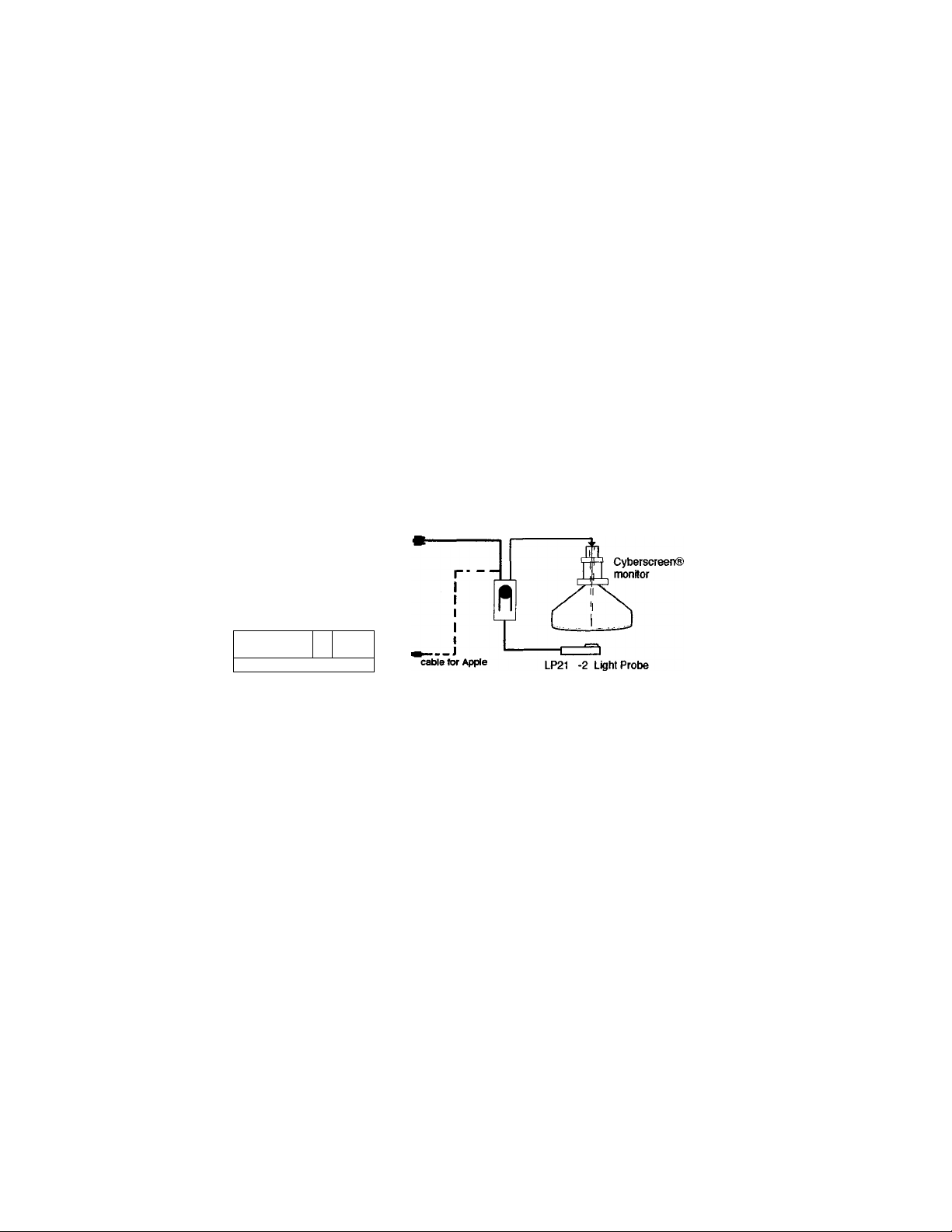
The calibrator system is based on a precision, high sensitivity light probe that com
municates with both the monitor and your computer thanks to a built in RS 232 inter
face provided to offer the maximum connection flexibility.
The Windows based software package provides an intuitive GUI (Graphic User
Interface) operation, so that you can start right now working with your new LP21 -2
Light Probe.
I
-J hI
Before you begin
Page 10

2 Getting started
Package Contents
Besides the 21XLP -2 Light Probe, the package also includes everything needed for
hardware installation and software configuration.
After unpacking, check that the shipment contains the following items:
- The 21XLP -2 Light Probe light probe unit
- The 21 XLP-2 Light Probe base unit
- Three (3) cables for interconnection
- This user guide
- The 21 XLP -2 Light Probe software disks (for Windows and Apple), enclosed in
the plastic envelope at the end of this guide
If any components are damaged or missing, contact your authorized dealer.
If you do not encounter problems at this stage, you can proceed with the installation.
IBM PC system requirements
The software requires an IBM PC compatible system (80386 or better) with:
- 4 Mb of extended memory
- Hard disk and a 3,5” high density FDD
- A free RS 232 port
- Miaosoft Windows 3.1 or greater
- Microsoft compatible mouse (recommended)
Appie PC system requirements
The software requires an Apple Personal Computer with:
- 4 Mb of extended memory
- Hard disk and a 3,5" high density FDD
- A freeModem port to connect the Mac RS232 adaptor
- System 7.0 or later
- mouse (recommended)
Your computer and monitor manuals would also be useful.
Getting started
Page 11

Installing the hardware
STEP 1
Choose a comfortable and secure location for the Light Probe unit, making sure that
the interconnection cables can reach both the monitor and the computer. Check that
either the device or the cables will not interfere when you tilt and swivel your moni
tor.
CauYioN: do not place the Light Probe unit on top of your monitor.
If you obstruct the air flow coming from the cabinet ventilation slots both the moni-
tor and the Light Probe unit can be damaged by excessive overheating.________________
CAuTloN: To prevent possible damage to equipment, both the computer and moni-
tor must be turned off before connecting or disconnecting any cable.
When connecting a cable, perform the operation carefully making sure that con-
nectors are well aligned during insertion.
STEP 2
Connect the cable having the 9 pin D - subminiature plug in type connector (male)
to the connector labeled SERIAL INTERFACE located on the back of your monitor.
STEP3
Connect the other end of the cable to the output port of the Light Probe unit, which
is marked as follows on the bottom of the unit:
_____________________________________
Gettin started
9
Page 12

STEP 4 (for Windows)
Connect the cable having the 9 pin D- sub miniature receptacle type connector
(female) to a free RS 232 port of your computer.
STEP 4 (for Apple)
Insert the RS232 Mac adaptor into the Modem port of your Apple PC and then con
nect on it the cable having the 9 pin D- sub miniature receptacle type connector
(female).
NOtE: In case all your serial ports are used, you will be required to temporarily
disconnect a peripheral device to allow the connection of the Light Probe unit.
If this is the case, choose any peripheral other than the mouse since its use will
greatly simplify the use of the Calibration software.
Use the adapter provided with the monitor accessories in case the Light Probe
should be connected to the 25 pole serial port of your PC..
STEP 5
Connect the other end of the cable to the input port of the Light Probe unit, which is
marked as follows on the bottom of the unit;
_________________________
9
STEP 6
Connect the cable of the 21XLP -2 Light Probe unit to the 8 pole Mini Din recepta
cle type connector located on the base unit. Keep the 21XLP -2 Light Probe in its
base housing.
Now that you have installed all the hardware parts of the 21XLP -2 Light Probe
package, you can proceed with the installation of the software.
Getting started
Page 13

Installing the software
Install software for Windows
STEP 1: Turn your system on and start the Windows session.
STEP 2: Insert the floppy disk with the 21XLP-2 Light Probe software.
STEP 3: From the Program manager File menu, select Run.
STEP 4: When the Windows dialog box appears, type the letter of the drive the
disk is in, followed by a colon and the word ‘setup’.
example : a ; setup
After a while , a ‘welcome’ box will appear on the screen. Just dick
‘Continue' to proceed with the installation.
Next, another box will be displayed, in which you need to select a dire
ctory where the installation program wiii install the files.
Default directory is C:\21XLP -2 ; you may change the target directory
by
typing a different one or just dick ‘Continue’.
In the next dialog box you will be requested to tell the program which
serial port of your computer the Light Probe is connected to.
Please check your computer documentation for identification of COM
ports. After this operation, the program will install the Light Probe softwa
re and, at the end of the installation, a new program group named
Cyberscreen II will be Created in the Program manager window.
This program group contains the calibration program icon labeled 21XLP
_2; just double dick on this icon to run the Light Probe application.
Install software for Apple
STEP 1 : Insert the floppy disk and double click on the floppy icon
STEP 2: Double click on the Installer Icon and select your language.
STEP 3: The set-up program will create a default folder named “Cyberscreen 11”
and will install all the files on the HD.
STEP 4: Now dick on the 21 XLP _2 icon from the “Cyberscreen II” folder to run
the software
Getting started
Page 14

Display identification and preset values saving
NOTE: every time the monitor is powered on, the first time you run the calibration
program a ‘zero calibration’ of the Light Probe is performed. During this operation,
identified by the program as
Dark measxire, place the probe in its base housing.
The first time you run the Light Probe appiication after the installation on your PC,
the program will perform the following steps:
STEP 1 - Display Identification
Since all the calibration and preset correction data are unique to the CRT of the
monitor you are now using, the program will prompt you to insert the serial ID num
ber of the display, which is printed on the back label of the monitor. For example , if
your monitor is labeled ‘prod.number: AN XXXXXX NNNNNN’, the useful ID number
consists of the last six NNNNNN digits.
Then, the number will be stored into the monitor memory and ail the correction data
saved on hard disk will be associated to it.
Every time you start the Light Probe software, the program will check if the monitor
in use is the one of which data are saved on hard disk.
STEP 2 - Data saving of preset corrections
After inserting the monitor serial number, the program will automatically create a
copy of all the preset correction values on your hard disk and will give you also the
option to create an additional back up copy on floppy disk.
During the copy, a window on the screen will indicate ‘Transmitting Data’.
CAUTION: in case you calibrate a different Brilliance 201CS on your PC, the program will notice the difference in the serial number (or absence, if the monitor is
brand new) and will prompt you the permission to ovenivrite the correction data on
hard disk. If you accept, you will permanently loose the data related to the previous
monitor unless you have previously made a back up copy on floppy disk.
_______________
Getting started
Page 15

How to start
From the Program manager window, open the cyberscreen ii program group
and double click on the 21xlp _2 icon to start the application.
You will be prompted to tell the program to which serial port the Light Probe is con
nected to and then, if necessary, a zero calibration of the Light Probe will be perfor
med.
Now the ‘Adjustment geometry’ pop up window will appears on the screen. By fol
lowing the instructions in the dialog box, adjust the black horizontal-verical borders.
3 White color calibration
About color temperature selection
If you are working with color images provided by different input sources (scanners,
laser discs, VCRs), calibration of the white coior temperature of your Brilliance
201CS according to the standard of the input source will enable the monitor to
display colors exactly as they were originally created.
On the other hand, if the work you create with your computer wiii be output on a TV
broadcast or reproduction system, or compared with an image created according to
a standard color proofing, white point calibration of the dispiay will ensure that what
you see on the screen will closely match what will be reproduced or printed out.
When you choose White color calibration from the White Temperature pop up
menu of the 21XLP -2 application window the following oalor reference models are
available;
-T1
-T2
■T3
Custom White settings
You can even select one of the above temperatures and then create Custom White
settings by typing the color temperature you wish to calibrate the display to, in case
you need to match a special Input or output device.
Steps of 100 Kelvin degrees are available inside the 5000 -10000 °K range.
9300 “K + 8 mpcd
6500 “K + 8 mpcd
5500<K
White color calibration
Page 16

Information on tvolcallv used color temperature:
D SO: this setting corresponds to the North American industry standard color temperature for
proofing coior photographs.
SSOO’K <T3 preseti : this settings is provided as an alternative to the D 50 standard, more
towards the blue end of the Black Body curve.
D 6S (T2 preset) : this setting reflects the NTSC color standard used for broadcast video.
Calibrate to this setting if the work you create wiil be output to a VRC or a TV unit.
9300°K + 8 mocd (T1 preset) : this is the brightest white point seiection, wideiy used in
CAD/CAM/CAE design environments.
Aithough used by most computer displays, this setting does not reflect any industry standard.
7500K ; this setting corresponds to the European industry standard coior temperature for
proofing color photographs.
In addition, with the white balance calibration option of the 21XLP -2 software you
can calibrate different Brilliance 201CS exactly to the same color reference model.
This wiil allow exchange of color image files with color consistency among all the
graphic workstations equipped with the Cyberscreen ® technology.
As a result, you can split works on a large color layout at several locations.
Calibrating the white color
NOTE: before you attempt to calibrate the white point, your system needs to be
‘warmed up’. Do not calibrate the display unless it has been operating for at least 30
min.
STEP 1
From the application window, select White color calibration from the white
tenperature pop up menu.
A dialog window will appear where you can select the white point you wish to adju
st. In the White preview box you will have an immediate preview of your selection
while the cie diagram will show you at which point of the black body curve is fal
ling the selected color temperature.
When you have done your selection, just click OK to continue.
White color calibration
Page 17

STEP3
After confirming the white seiection, the screen will turn into a full white page pat
tern. Put the Light Probe at the center of the screen and click OK.
NOYE: in case the purpose of the calibration is to match two 21” Cyberscreen ®
displays at different locations, make sure that ambient lighting conditions are simi
lar. Due to the fact that the calibration probe is slightly sensitive to ambient illumi
nation, if a monitor is calibrated in a very dark environment while another is cali
brated when the sun is shining on the screen from the office window you may have
different results.
NOTE: in case the purpose of the calibration is to match two 21” Cyberscreen ®
displays, make sure that settings of both Brightness and Contrast are the same.To
assure that, please take note of the reading of the luminance meter displayed on
the dialog box, below the level bar indicator.___________________________________
STEP3
At this point, the screen will turn into full red page pattern. Put the Light Probe at
the center of the screen and click OK to perform the calibration. The program will
automatically measure and adjust to the proper value the three RGB primary colors
and then the data will be saved into the monitor memory.
10
White color calibration
Page 18

4 Brightness and color uniformity calibration
About brightness and color uniformity
Your 21 ” Cyberscreen ® monitor has been precisely aligned at the factory to get the
best performances out of the picture tube/electronic drive system combination by
using the most advanced automatic alignment techniques.
However, like all the CRT based display systems, the color reproduction is sensiti
ve to drift during the product lifetime and this can create problems if you are invol
ved in creating color artworks with your computer.
With the LP21 -2 software you can keep your display performances under control
and, when necessary, perform by yourself an uniformity re-calibration which has the
same precision of the alignment we perform at factory.
Use the following procedure to easily determine if your display needs calibration:
NQI E: I he following procedure must be performed only after 30 min. monitor ‘warm
HEL
__________________________________________________________________________
STEP 1
From the Measure menu of the LP21 -2 application window, select Brightness
option. A full white page pattern divided into 25 areas will appear, together with a
dialog box displaying the current Light Probe reading (value is given in both Foot-
Lambert, Fl,.and Candela per Square meter. Nit).
NOTE: before proceeding with SIhP 2, select the color temperaure you want to
calibrate, from the dialog box that appears on the screen.
__________________________
STEP 2
Put the Light Probe to the screen center (area 13) and measure its brightness value
(Nit or FI).
At this point, just put the Light Probe on any area you think to be criticai
and, by comparing the current reading to the reference one taken at the screen cen
ter, you can check the overall brightness uniformity.
As option, you can also check the screen uniformity for each of the Red, Green and
Blue colors.
White uniformity calibration 11
Page 19

If the difference between readings at any point of the screen and the reference cen
ter is found to be greater than 10%, then the display needs to be re-calibrated.
In that case, two different calibration options are avaiiabie:
Local uniformity: this is a quick calibration process; use this option if just one area
of the screen needs to be calibrated.
Global uniformity: this is the complete calibration procedure; use this option if seve
ral areas on the screen need calibration.
Calibrating the screen uniformity
NOTE: before you attempt to calibrate the screen uniformity, your system needs to
be ‘warmed up’. Do not caiibrate the display unless it has been operating for at least
30 min.
Local uniformity
STEP 1
From the uniformity menu of the 21XLP -2 appiication window select Execute
Local Uniformity.
The screen will turn into a white pattern divided into 25 areas, a dialog box will
appear on the screen and you will be prompted to insert the area number you wish
to calibrate. When done, click OK to continue.
STEP 2
The screen will turn into a full white page; put the Light Probe at the center of the
screen and click OK.
Now the screen will turn into full red, full green and full blue.
Next, you will be prompted to lean the Light Probe on the area to be calibrated.
When done, just click OK and the program will adjust that point to the same value
as measured at the screen center, designated as reference point. This procedure
will be executed for the three RGB primary colors;
NOTE: During calibration you may see that the screen is ‘flashing’. This is simply
due to the high updating speed of the correction system.
The program will then repeat the above described operation for the green and blue
colors.
_________________________
12 White uniformity calibration
Page 20

When calibration has been completed, you will be asked to save the calibration
results: if you choose Cancel, the calibration will be discarded; if you want to save
just click OK and then assign a name to the new correction file (default extension is
.BRG).
Global uniformity
STEP 1
From the uniformity menu of the 21XLP -2 application window select Execute
Global Uniformity.
The screen will turn into a full red page pattern. Put the Light Probe at the center of
the screen and click OK.
At this point, the program will start increasing/decreasing step by step the correc
tion value for the red gun and for each value it will measure the light output respon
se. The purpose of this operation is to obtain a correlation between light output and
correction increment.
ImOtE: During measurements you may notice ‘flashing’ on the screen. This is sim
ply due to the high updating speed of the correction system._________________________
The program will then repeat the above described operation for the green and blue
guns.
STEP 2
After verifying the light output response for each of the RGB guns, the screen will
turn into a full white page again. Put the Light Probe at the screen center and click
OK; the program will measure the absolute value at this point and will keep it as a
target value for the calibration.
STEPS
Next, awhite page pattern divided into 25 areas will appear and you will be promp
ted step by step to put the Light Probe on the whole screen area, starting from Area
1 to Area 25.
STEP 5
When calibration has been completed, you will be asked to save the calibration
results: if you choose cancel, the calibration will be discarded; if you want to save
just click OK and then assign a name to the new correction file (default extension is
.BRS) .
White uniformity calibration 13
Page 21

Loading factory presets and user’s correction tables
The factory data of your monitor have been saved on hard disk during the 21XLP 2 software installation; to recall the original monitor uniformity correction table, just
select Restore factory data from the Uolformity menu of the 21XLP-2 appli
cation.
With the Get user data selection of the uniformity menu, you can down load
to the monitor any of the calibration tables you have previously saved on the disk.
14
White uniformity calibration
Page 22

5 Convergence adjustment
About convergence
Even though the purpose of the 21XLP -2 Light Probe is to measure and calibrate
colors, the software furnished with it allows you to get full control of the DDA cx3r-
rection system of your Brilliance 201CS display, including the digital convergence
correction section.
As already discussed in Chapter 1, the DDA correction system works by dividing the
screen into a 16x16 matrix and with the ability of controlling the beam position for
each of the resulting 256 areas. By using the Convergence option of the 21XLP 2 application software, you can refine by yourself the convergence virtually at any
point of the screen and then save your adjustment in the monitor memory.
As a matter of fact, convergence of your monitor has been already set for the best
performances in our factory and should not require any further adjustment, being a
parameter that normally does not show drifts due to picture tube aging.
However, you can check the performances of your monitor by activating the Test
pattern option, available from the Convergence pop up menu of the 21XLP -2
application.
NÖTE: Convergence check should be performed only after 30 min. monitor ‘warm
_______________________________________________________________
First, a Red-Green-Blue crosshatch pattern will be displayed; if you click the OK but
ton in the small dialog box then a White crosshatch will be displayed. Click OK again
and the last pattern, a Magenta (red + blue) crosshatch, will appear.
All of them are suitable for evaluating the convergence of your display; if you notice
some areas where performance could be improved, then proceed with the conver
gence adjustment.
Convergence adjustment 15
Page 23

Adjusting the convergence
NOTE: before you attempt to adjust the convergence, your system needs to be ‘war
med up’. Do not calibrate the display unless it has been operating for at least 30 min.
NOTE: every time you run the 21XLP -2 application, the program will be searching
for the Light Probe unit. For this reason, even if the Light Probe will not be used
during convergence adjustment it must remain connected to the system.
____________
__
STEP 1
From the 21XLP -2 application window, select Execute calibration from the
Convergence pop up menu. A dialog box will appear indicating saving present
values, while the program is saving the current monitor configuration.
STEP 2
Global convergence adjustment.
NOTE: Global convergence is provided tor screen center adjustment. It you do not
notice convergence errors in this area, just click OK to proceed with next step.
A Red-Blue crosshatch pattern will be displayed at the center of the screen, together
with a dialog box where all the adjustment options for this step are listed.
Two options are available, for both the horizontal and vertical lines of the crosshat
ch:
(Hor/Ver) R,B
This option adjusts the relative position of the Red and Blue beams so that they can
converge each other. In most cases, once you have assured the convergence of
Red and Blue beams, the convergence with the Green beam is automatically achie
ved since, due to the gun design, this beam is the central one.
However, due to small gun imperfections, in some cases even if the RB convergen
ce is adjusted, the Green beam can still be resolved as a single color. If that is the
case, you may use the next adjustment option.
(Hor/Ver) G,M
This option adjusts the position of the Green beam with respect to the position of
the Red and Blue beams together (the combination of which generates the Magenta
16
Convergence adjustment
Page 24

color).
Use this adjustment if, after performing the R,B adjustment, the Green beam can
still be perceived as a single color.
NÖTE: the Global convergence adjustment behavior reflects the so called ‘static
convergence’ adjustment as available on some computer displays. Although this
option is provided to adjust convergence errors at the screen center, remember that
any change in beam positions made with this option will change the beam positions
for the whole screen area.________________________________________________
When your adjustment is complete, click OK to continue.
STEP3
Local Convergence adjustment
A Green-Magenta crosshatch pattern will be displayed, together with a dialog box
where all the adjustment options for this step are listed.
This adjustment step, by using the same options as described in the step 2
(Red to Blue and Green to Magenta adjustments), allows you to correct the misconvergence individually at any point of the screen.
The green box identifies the area where the correction will take place; use the
tJt)/Down and Left/Right buttons to move the adjustment area to the point you
wish to correct, then act on ’+’ and buttons to adjust the convergence.
In addition to the single point adjustment (default), if you select the Row adjust
ment option the correction will apply horizontally for the whole area prior to and fol
lowing the green adjustment box.
If you select the column adjustment option, the correction will take place vertically
for the whole area prior to and following the green box.
When done, click OK to terminate the convergence adjustment.
STEP 4
When calibration has been completed, you will be asked to save the results of your
adjustment: if you choose Cancel, the calibration will be discarded; if you want to
save just click OK and then assign a name to the new correction file (default exten
sion is .CNV).
Convergence adjustment
17
Page 25

Loading factory presets and user’s correction tabies
The factory data of your monitor have been saved on hard disk during the 21XLP 2 software instaliation; to recaii the original monitor uniformity correction table, just
select
Restore factory data from the Convergence menu of the 21XLP -2
application.
With the Get user data selection of the Convergence menu, yOU can down load
to the monitor any of the adjustment tables you have previously saved on the disk.
18
Convergence adjustment
Page 26

6 Cleaning and maintenance
After a calibration process, the rubber cup of the Light Probe may leave circular
prints on the monitor screen.
To clean these rings, first shut down your computer and turn off the power to the
monitor.
Moisten a lint-free cloth with a diluted household glass cleaner and then use the
cloth to wipe the monitor screen.
The same cieaning can be used also for the rubber cup of the Light Probe.
fcALlTiONl: do not spray glass cleaner directly onto the screen. It may drip down
below the plastic case and damage circuitry within the monitor._______________________
Due to the very small power usage of the LP21 -2 Light Probe circuitry, you do not
need to disconnect it from the system after the calibration of your display.
However, if you plan not to use the device for a long period of time we suggest to
have it removed from the system and safely stored in its original packing.
Remember that the LP21 -2 Light Probe contains highiy sophisticated and delicate
circuits: use common sense when handiing it.
Cleaning and maintenance 19
Page 27

What’s behind
This last section of the User’s guide introduces you to the theory of color perception
and describes how your monitor can display color images.
It briefly explains also the limitations of a traditional CRT display system and the
innovations of the Cyberscreen ® technology.
Color basics
Surprisingly, color as such does not exist in nature.
What happens is that human eye is sensitive to different frequencies of the
Electromagnetic Radiation which we call light.
The fact that light is the source of color was demonstrated by Isaac Newton in 1666
with the so called ‘prism experiment’: he experienced that a beam of sunlight pas
sing through a glass prism was broken up into a rainbow made of all the visible
colors. Further to that, he passed the resulting rainbow of light through a second
prism and found that the array of colors was reassembled into the original white light
beam.
As a conclusion of the experiment, it was demonstrated that white light is made up
of and can be reproduced by a mix of colored lights.
According to the color theory fundamentals concerning transmitted light, just the
Red, Green and Blue colors are required to create white light, and it is demonstra
ted that by varying the intensity of these colors the whole color spectrum can be
reproduced.
For this reason, Red, Green and Blue color are defined as Additive Primary Colors.
20
Appendix A
Page 28

How displays create colors
A color display, being a CRT based device, acts itself as a light source and the way
how it creates colors is based on the aforesaid Additive principle.
The inside surface of the CRT screen is coated with three special type of phosphors
that, when struck by high energy electrons, glow with particular frequencies of light
perceived respectively as the Red, Green and Blue primary colors.
The phosphors are arranged in groups of 3, called triads, with each phosphor being
driven by one of the three RGB guns. A perforate metal shield known as shadow
mask acts as a filter to separate the three electron beams so that they can strike the
designated phosphors only.
As the three electron beams scan each video line, they pass in turn through each
slot in the shadow mask and impinge on their respective phosphor in the associa
ted triad.
The perceived color is thus a combination of the three primary colors depending on
the relative magnitude of the three RGB beam currents; if all the guns fire at full
intensity then white light is perceived; if just one gun hits its corresponding phosphor
then a single color is perceived; if none of the dots are hit the triad remains biack.
The combination of these glowing phosphors, addressed by the video input signal
coming from your computer, creates the color images you see on the screen.
About color uniformity
Because of traditional limitations in CRT technology, most large screen color moni
tors show uneven brightness over the total screen area.
For example, the fact itself that CRT glass thickness is increased at the screen cor
ners to improve mechanical resistance or a non uniformity in shadow mask hole
sizes will cause a lack of brightness in these areas, while a non uniformity in pho
sphors displacement or sensitivity will show some areas where color characteristics
are different from others.
When some areas of the screen are brighter or show different colors than others,
then image quality decreases and ‘real life’ images reproduction cannot be granted
anymore, especially when the monitor is used for creating color artworks electroni
cally.
Appendix A 21
Page 29

The 21” Cyberscreen ® monitor state of the art technology
Your Cyberscreen ® monitor has put a milestone in CRT color display technology.
Thanks to its unique DDA system (Digital Dynamic Adjustment), the drives of the
RGB guns are digitally controlled over the entire screen so that the monitor electro
nics can compensate for the lack of color and brightness uniformity of the picture
tube.
This system divides the screen into a 16x16 matrix (@ 1024*768) and for each of
the resulting 256 areas the RGB drive circuits of the electron guns can be indivi
dually tuned, resulting in an outstanding uniform and precise image.
With the Brilliance 201CS, the whole screen area can be really used as a ‘work
space’for creating professional color works, with an unconditional uniformity in color
and brightness from the center to the boundaries of the screen.
Expressing colors: CIE system
As previously described, by blending the three frequencies of light the eye is sensi
tive to, it is possible to represent any of the rainbow colors.
What happens is that these three signals are sent undecoded to the brain, where
they are mixed and interpreted. In other words. Humans perceive color rather than
‘see’ it.
For that reason, color expressions often means different colors to different people,
and so it is very hard to relate a color to another person and having the other per
son interpret it in the same way we perceive it.
The problem of expressing colors more precisely than with words was first faced in
1931 by the ‘Commission Internationale de L’Eclarage’, that designed the so called
Tristimulus Chart, more simply known as the CIE 1931 Chart.
By means of this chart, the Chromaticity of a color can be broken down in two coor
dinates called X and y, while the Luminance of the color is represented by Y.
In other words, x and y coordinates tell us ‘what color it is’, while the figure Y gives
us the ‘brightness’ of that color.
22
Appendix A
Page 30

The numbers x and y do not have units of measurements; while there are two main
units of measurement of factor Y in use today: ‘Candela per square meter” (Nit) and
‘Foot Lamberts’(FI).
If we consider your Brilliance 201CS monitor, it has three preset RGB white balan
ce adjustments that, according to the CIE xyY system, can be defined as follows:
Preset 1 X = 0,283 y -= 0,298 Y > 28 Foot Lamberts
Preset 2 x - 0,313 y = 0,329 Y > 23 Foot Lamberts
Preset 3 X = 0,332 y = 0,347 Y > 23 Foot Lamberts
Color temperature
According to the Black body radiation theory in physics, an ideal object will glow with
a characteristic color when heated. The color can be calculated mathematically and
it can be shown that as the temperature increases this glow moves from infra red
through dull red, orange, yellow, yellow white and eventually to bluish white.
As the color produced at a given temperature can be precisely predicted, then it is
possible to define white light in terms of color temperature.
The white point color temperature is therefore a measure in Kelvin degrees of ‘how
white’ a white is.
Back to your Brilliance 201 CS, the Preset 1 adjustment corresponds to a color tem
perature of 9300 Kelvin degrees and shows a bluish tint; Preset 2 is set to 6500
Kelvin degrees and has a reddish tint. Preset 3 is set to 5500 Kelvin degrees.
As an additional example, the color temperature of sunlight at noon, when the sun
is shining directly overhead, is approximately 5000 Kelvin degrees.
Appendix A
23
Page 31

The convergence problem
The electron guns in a color CRT are mounted alongside each other and in most
cases they are placed in line.
This is necessary for the shadow mask in fiitering out the eiectron beams on their
way to the front of the screen, so that they can reach the designated phosphor oniy.
The problem with this system is that the offset beams travei along different paths
and may fail to hit the same phosphor triad, as instructed by the computer. This is
caiied convergence error and it is usualiy perceived as a fringing around the dots
on the screen.
in severe cases, a dot or a iine designated to be as ‘white’, may be completely resol
ved into its red, green and blue components.
The problem of convergence is usually more noticeable when the beam approaches
the screen corners, where the beams path lengths offset reach its maximum.
The Cyberscreen ® solution
The convergence problem has been solved in your Brilliance 201CS by using the
same approach as previously described about the screen uniformity.
The built in DDA system divides the screen in a 16x16 matrix and, for each of the
resulting areas, the beams position and so the convergence can be precisely opti
mized.
As a result, all the conventional CRT errors can be cximpensated so that the
displayed image can only be as sharp and precise as you have never seen before.
24 Appendix A
Page 32

B Error messages
If system displays;
2lXliP not connected
It means that the application program is unable to locate the Light Probe unit at the
selected serial port. Check if aii the cabies are properiy connected and if the serial
port you specified is the right one.
Once you have fixed the problem, you need to switch the monitor off and then on
again to recover the error condition.
If system displays:
21XLP not connected
it means that the appiication program has detected a missing connection between
the base unit an the Light Probe unit of the 21XLP -2 Light Probe. Please check the
proper connection of the Light Probe cabie to the base unit.
Once you have fixed the probiem, you need to switch the monitor off and then on
again to recover the error condition.
if system displays:
Monitor not connected
it means that your dispiay does not respond to the caiibration program.
Please check if the sériai port of the monitor and the output port of the 21XLP -2
base unit are properiy connected.
if system displays:
2IXI1P setup error
means that during the Light Probe zero calibration (dark measure) an overfiow con
dition occurred. Please assure that the Light Probe is properiy placed in its base
housing and restart calibration.
Appendix B
25
Page 33

If system displays:
Fatal error - please restart the program
it means that an unrecoverable communication error has occurred during the cali
bration process(e.g. the monitor has been turned off).
Piease restart both the monitor and the calibration program.
If system displays:
Harnlog: the syst^ has detected a configuration error,
sor box does not match
.........
The sen-
it means that the you have mismatched either the Light Probe unit or the base unit
of your caiibration system with a device belonging to a different 21XLP Light Probe
package.
The Light Probe and base unit combination within each calibration package are pre
cisely matched and tuned, for the maximum measurement accuracy.
Please check if both components of your calibration system are belonging to the
same 21XLP -2 Light Probe shipment.
If system displays:
Measure of light not correct
it means that 21XLP Light Probe zerois not properly placed on the screen.
26 Appendix B
Page 34

СлЭ
CD
K>
О
<У)
tV)
00
03
03
*
Printed in itaiy - RevOI/9648
 Loading...