


30" Wide LCD-TV Color Monitor
Service
Service
Service
TABLE OF CONTENTS
Description
Important Safety Notice..................................2
Technical Specification...................................3~4
Connecting The Monitor..................................5~7
Control and Inputs..........................................8~11
OSD User Mode.............................................12~17
Warning Message...........................................18
Troubleshooting.............................................19~20
Failure Mode of LCD Panel............................. 21
Definition of Pixel Defects...............................22
Wiring Diagram..............................................23
Mechanical Instructions..................................24~25
Display Adjustment........................................26~27
Safety Test Requirements...............................28
DDC Instructions............................................29~32
DDC Data.................................................... .33~34
Repair Flow Chart..........................................35~38
Function Block Diagram..................................39
Power Diagram..............................................40
I/O & Interface Diagram..................................41
Video Decoder Diagram..................................42
Scaler Diagram..............................................43
LVDS Tx Diagram......................................... .44
SDRAM Diagram............................................45
PC-Analog In Diagram....................................46
Page
LMT2 300WN5
300WN5QS/97
Horizontal frequencies
31 - 49 kHz
Description
Scaler-Up Diagram.........................................47
Video Converter Diagram................................48
HDTV Decoder Diagram..................................49
Painter Diagram............................................ .50
PC DVI_Digital Diagram..................................51
TMDS_Rx Diagram.........................................52
Audio Delay Diagram......................................53
Audio Board Diagram-1...................................54
Audio Board Diagram-2...................................55
Key Control Board Diagram and C.B.A.............56
IR PCB Diagram and C.B.A .............................57
Rs232 PCB Diagram and C.B.A.......................58
Audio Out Jack PCB and C.B.A........................59
TV Box PCB(Video) Diagram. .........................60~64
TV Box PCB(TV) Diagram...............................65~69
Scaler PCB C.B.A-1 and -2..............................70~71
Audio PCB C.B.A............................................72
TV Box PCB(Video) C.B.A...............................73
TV Box PCB(TV) C.B.A...................................74
Power Circuit Diagram and C.B.A....................75~76
Exploded View................................................77
Spare Parts List..............................................78~81
Different Part List............................................82~87
Page
ANY PERSON ATTEMPTING TO SERVICE THIS CHASSIS MUST FAMILIARIZE HIMSELF WITH THE CHASSIS
AND BE AWARE OF THE NECESSARY SAFETY PRECAUTIONS TO BE USED WHEN SERVICING ELECTRONIC
EQUIPMENT CONTAINING HIGH VOLTAGES.
CAUTION: USE A SEPARATE ISOLATION TRANSFORMER FOR THIS UNIT WHEN SERVICING.
REFER TO BACK COVER FOR IMPORTANT SAFETY GUIDELINES
Published by BCU Monitor Printed in Taiwan Copyright reserved Subject to modification Mar 18 2004
©
SAFETY NOTICE
F
GB
3138 106 10356

2
300WN5
Go to cover page
Important Safety Notice
Proper service and repair is important to the safe, reliable
operation of all Philips Company** Equipment. The service
procedures recommended by Philips and described in this
service manual are effective methods of performing service
operations. Some of these service operations require the use
of tools specially designed for the purpose. The special tools
should be used when and as recommended.
It is important to note that this manual contains various
CAUTIONS and NOTICES which should be carefully read in
order to minimize the risk of personal injury to service
personnel. The possibility exists that improper service
methods may damage the equipment. It is also important to
understand that these CAUTIONS and NOTICES ARE NOT
EXHAUSTIVE. Philips could not possibly know, evaluate and
advise the service trade of all conceivable ways in which
service might be done or of the possible hazardous
consequences of each way. Consequently, Philips has not
undertaken any such broad evaluation. Accordingly, a
servicer who uses a service procedure or tool which is not
recommended by Philips must first satisfy himself thoroughly
that neither his safety nor the safe operation of the equipment
will be jeopardized by the service method selected.
* * Hereafter throughout this manual, Philipsl Company will
be referred to as Philips.
WARNING
Critical components having special safety characteristics are
identified with a by the Ref. No. in the parts list and
enclosed within a broken line*
(where several critical components are grouped in one area)
along with the safety symbol on the schematics or
exploded views.
Use of substitute replacement parts which do not have the
same specified safety characteristics may create shock, fire,
or other hazards.
FOR PRODUCTS CONTAINING LASER :
DANGER-
CAUTION-
CAUTION-
TO ENSURE THE CONTINUED RELIABILITY OF THIS
PRODUCT, USE ONLY ORIGINAL MANUFACTURER'S
REPLACEMENT PARTS, WHICH ARE LISTED WITH THEIR
PART NUMBERS IN THE PARTS LIST SECTION OF THIS
SERVICE MANUAL.
Invisible laser radiation when open.
AVOID DIRECT EXPOSURE TO BEAM.
Use of controls or adjustments or
performance of procedures other than
those specified herein may result in
hazardous radiation exposure.
The use of optical instruments with this
product will increase eye hazard.
Take care during handling the LCD module with backlight
unit
- Must mount the module using mounting holes arranged in four
corners.
- Do not press on the panel, edge of the frame strongly or electric
shock as this will result in damage to the screen.
- Do not scratch or press on the panel with any sharp objects, such
as pencil or pen as this may result in damage to the panel.
- Protect the module from the ESD as it may damage the electronic
circuit (C-MOS).
- Make certain that treatment person’s body are grounded through
wrist band.
- Do not leave the module in high temperature and in areas of high
humidity for a long time.
- Avoid contact with water as it may a short circuit within the module.
- If the surface of panel become dirty, please wipe it off with a soft
material. (Cleaning with a dirty or rough cloth may damage the
panel.)
Under no circumstances should the original design be
modified or altered without written permission from Philips.
Philips assumes no liability, express or implied, arising out of
any unauthorized modification of design.
Servicer assumes all liability.
* Broken Line

Technical Data
300WN5
Go to cover page
3
Technical Specifications*
LCD PANEL
Type : TFT LCD
Screen size : 29.5 inch
Pixel Pitch : 0.5025 x 0.1675 mm x RGB
LCD Panel type : 1280 x 768 pixels
Effective viewing area : (H) 643.2 x (V) 385.92mm
Display Colors:8bitsinterface (16.7M colors)
PC SCANNING
Vertical refresh rate : 58Hz-60Hz
Horizontal frequency : 31kHz-49kHz
PC VIDEO
Video dot rate:<80MHz
Input impedance
-Video:75ohm
- Sync : 2.2K ohm
Input signal levels : 0.7 Vpp
Sync input signal : Separate sync
Sync polarities : Positive and negative
Input Frequency : WXGA Hsync 48 kHz, Vsync 60 Hz (N.I.)
Video interface : D-sub, S-Video, TV-RF, SCART (Europe) or
AUDIO
Input level for PC/SVHS/SCART : 500 mV nominal
Loudspeaker : 5W Stereo Audio (2.5W/channel RMS x2,
OPTICAL CHARACTERISTICS
Contrast ratio : 500:1 (typ.)
Brightness : 500 cd/m2 (typ.)
Peak contrast angle:6o'clock
White Chromaticity : x: 0.283 y: 0.297 (at 9300K)
Viewing Angle (C/R >5) : Upper >88 degree(typ.)
Response time <=16ms (typ.)
sRGB
sRGB is a standard for ensuring correct exchange of colors
between different devices (e.g. Digital cameras, monitors,
printers, scanners, etc.) Using a standard unified color space,
sRGB will help represent pictures taken by an sRGB compatible
device correctly on your sRGB enabled Philips monitors. In that
way, the colors are calibrated and you can rely on the correctness
of the colors shown on your screen. Important with the use of
sRGB is that the brightness and contrast of your monitor is fixed
to a predefined setting as well as the color gamut. Therefore it is
important to select the sRGB setting in the monitor's OSD.
To do so, at PC mode, open the OSD by pressing the MENU
button of your monitor. Use the down button to go to COLOR
SETTINGS and press MENU again. Then move the down button
to go to NORMAL COLOR and press MENU again. For more
information on sRGB, please visit:
R.G.B. vertical stripe
Hard coating surface, anti-glare polarizer
SVGA Hsync 38 kHz, Vsync 60 Hz (N.I.)
VGA Hsync 31 kHz, Vsync 60 Hz (N.I.)
composite and components video (others)
200Hz~10kHz, 4 ohm, 10% THD)
x: 0.313 y: 0.329 (at 6500K)
x: 0.328 y: 0.344 (at 5700K)
Lower >88 degree (typ.)
Left >88 degree (typ.)
Right >88 degree (typ.)
www.srgb.com
Resolution Mode H. freq (kHz) V. freq (Hz)
PC
640*480 VGA VESA 60 31.469 59.940
800*600 SVGA VESA 60 37.879 60.317
1024*768 XGA VESA 60 48.363 60.004
1280*768 GTF 60 47.700 60.000
Video
EDTV 480P 31.470 60.000
SDTV 480i 15.734 59.940
EDTV 576P 31.250 50.000
SDTV 576i 15.625 50.000
HDTV 1080i 33.750 60.000
HDTV 720P 45.000 60.000
Automatic Power Saving
If you have VESA DPMS compliance display card or software
installed in your PC, the monitor can automatically reduce its power
consumption when not in use. If an input from a keyboard, mouse or
other input device is detected, the monitor will then 'wake up'
automatically. The following table shows the power consumption
and signaling of this automatic power saving feature:
Power Management Definition
VESA Mode Video H-sync V-sync Power Used LED color
ON Active Pulse Pulse 130W (typ.) Blue
OFF Blanked No No <5W Amber
AC OFF Blanked No No <2W Off
Physical Specifications
Dimension (WxHxD) : 867.7mm x 505mm x 183mm (incl.
Pedestal, Speakers)
726.7mm x 469.3mm x 115mm (w/o
Pedestal, Speakers)
Weight:16.0 kg (incl. Pedestal, Speakers)
14.0 kg (w/o Pedestal, Speakers)
15.0 kg (w/o Pedestal, Speakers; with protective cover)
Power supply : 90 +/- 264 VAC, 50/60 Hz
Power consumption
-PC Mode: 130 W (typ.)
-TV Mode: 150 W (typ.)
Temperature (operating):0Cto35C
Relative humidity : 20% to 80%
* This data is subject to change without notice.
Resolution & Preset Modes
Recommended : 1280 x 768 at 60Hz
10 factory preset modes:

4
300WN5
Go to cover page
Technical Data
Pin Assignment
1. The digital only connector contains 24 signal contacts organized in
three rows of eight contacts. Signal pin assignments are listed in the
following table:
Pin
Signal Assignment
No.
1 T.M.D.S. Data2- 9 T.M.D.S. Data1- 17 T.M.D.S. Data0-
2 T.M.D.S. Data2+ 10 T.M.D.S. Data1+ 18 T.M.D.S. Data0+
T.M.D.S. Data2/4
3
Shield
4 No connect 12 No connect 20 No connect
5 No connect 13 No connect 21 No connect
6 DDC Clock 14 +5V Power 22
7 DDC Data 15 Hot Plug Detect 23 T.M.D.S. Clock+
8 No connect 16 Ground (for +5V) 24 T.M.D.S. Clock -
Pin
Signal Assignment
No.
T.M.D.S. Data1/3
11
Shield
Pin
Signal Assignment
No.
T.M.D.S. Data0/5
19
Shield
T.M.D.S. Clock
Shield
2. The 15-pin D-sub connector (male) of the signal cable:
Pin No. RS-232 (EIA-232-A) Function
3 Transmit Data (TD) from DTE to DCE
2 Receive Data (RD) from DCE to DTE
7 Request to Send (RTS)
8 Clear to Send (CTS)
6 DCE Ready (DSR)
5 Signal Ground (SG)
1 Received Line Signal Detector (DCD)
4 DTE Ready (DTR)
9 Ring Indicator
4. SCART Connector
Pin
No.
Assignment
Pin
No.
Assignment
1 Red video input 9 DDC +5V
2 Green video input 10 Cable detect
3 Blue video input 11
Identical output,
connected to pin 10
4 Ground 12 Serial data line (SDA)
5 NC 13 H. Sync / H+V
6 Red video ground 14 V. Sync
7 Green video ground 15 Data clock line (SCL)
8 Blue video ground
3. RS232 Connector
D-sub 9-pin male connector for communication with plasma engine or
PC.
Pin
No.
1 Audio right channel output (0.5 Vrms, < 1K ohms) 2
2 Audio right channel input (0.5 Vrms, > 10K ohms) 1
3 Audio left channel output (0.5 Vrms, < 1K ohms) 6
4 Audio ground 4
5 Blue signal ground 5
6 Audio left channel input (0.5 Vrms, > 10K ohms) 3
7 Blue signal I/O (0.7 Vp-p, 75 ohms) 7
8 Function switching I/O (L: < 2V, H: > 10V, 10K ohms) 8
9 Green signal ground 9
10 Intercommunication data line No. 1 10
11 Green signal I/O (0.7 Vp-p, 75 ohms) 11
12 Intercommunication data line No. 2 12
13 Red signal ground 13
14 Blanking signal ground 14
15 Red signal I/O (0.7 Vp-p, 75 ohms) 15
16 Blanking signal I/O (L: < 0.4V, H: >1.0V, 75 ohms) 16
17 Composite video signal ground 18
18 Blanking signal ground 17
Composite video signal output (1 Vp-p, 75 ohms, sync:
19
negative)
20 Composite video signal input (1 Vp-p, 75 ohms, sync: negative) 19
21 Plug shield (common ground) 21
Signal Pin
No.
20

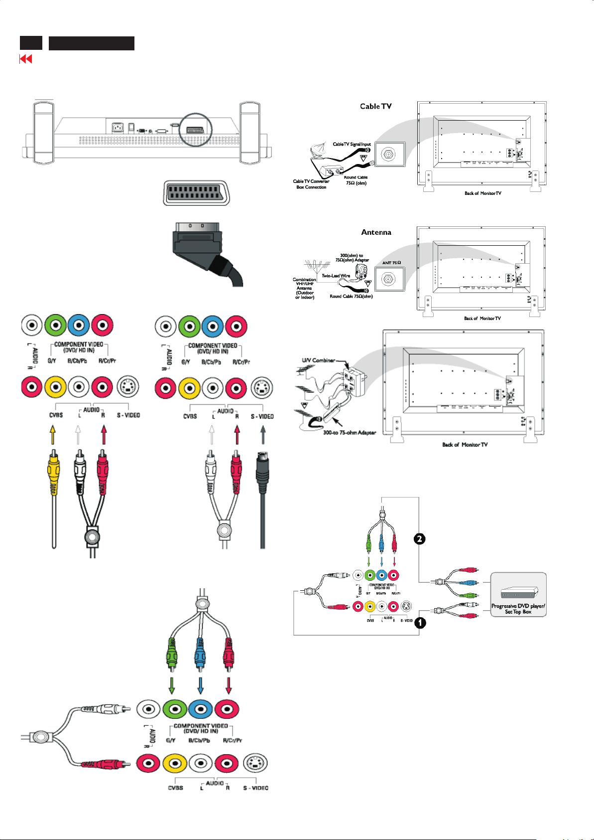
Connecting The Monitor
Connecting the monitor/TV
Connect the cables to the rear of your monitor/TV according to the
numbers:
TV model
300WN5
Go to cover page
5
Audio/Video model
Connect to DVD/VCR/VCD through S-VIDEO
Monitor model
6
300WN5
Go to cover page
Connecting The Monitor
Connect to DVD/VCR /VCD through SCART (for Europe only)
Connect to DVD/VCR /VCD through composite video (CVBS)
Connecting to Cable TV
Antenna
Connect to DVD/VCR /VCD through component video (YPbPr)
Progressive video and HDTV connections for digital highdefinition picture

Connecting The Monitor
300WN5
Go to cover page
7
Connect to PC

8
300WN5
Go to cover page
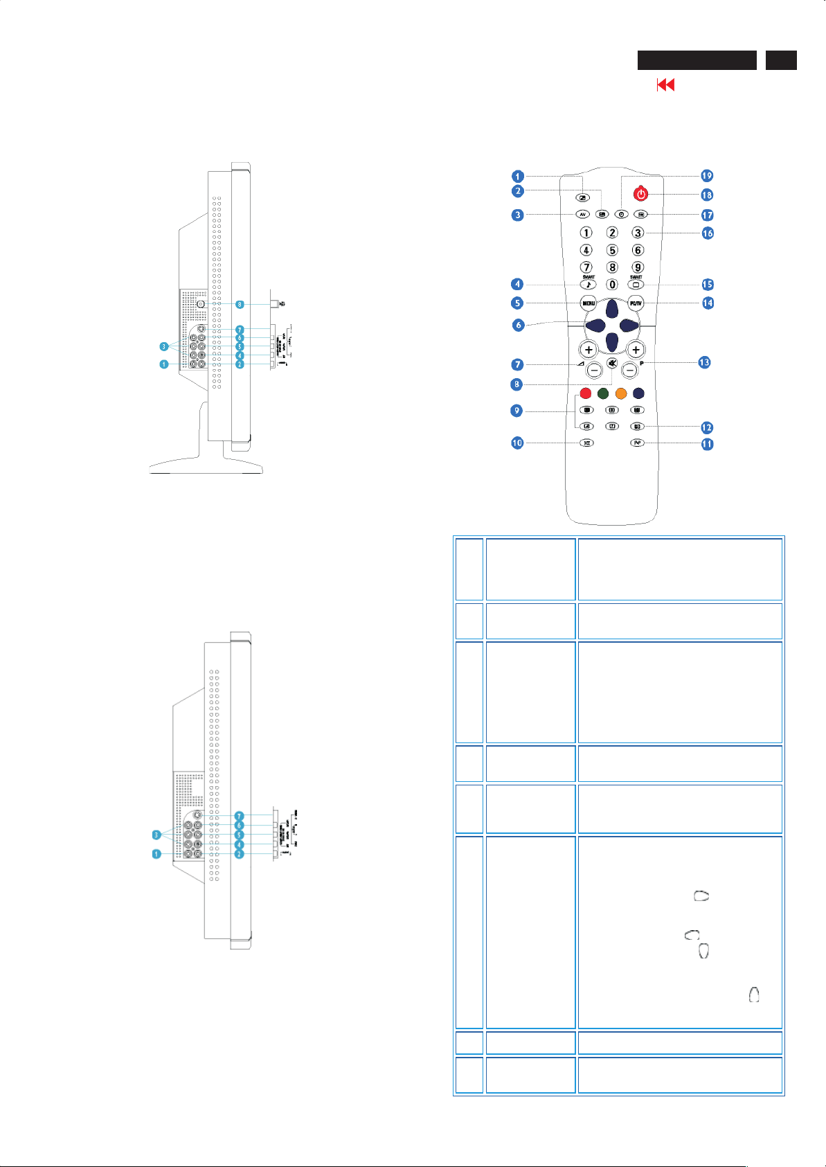
Control and Inputs
Side View (Left)
INPUT
1 Selecting input source
2 Increase or decrease the channel number
3 Increase or decrease the level of audio volume
4 Open the OSD or confirm the selected function
MENU
5 DC power switch On/Off
Rear View
TV version
or moving up or down to highlight the function in OSD
or moving left or right to highlight the sub-menu in the
selected function ofOSD
Audio/Video version
1. AC IN : AC power in
2. AC Power : AC power switch
3. D-Sub: PC analog D-Sub input
4. PC - Audio : PC Stereo input
5. DVI-D : PC digital DVI-D input
6. Rs232 : RS232 network connection
7. External/EURO-AV : SCART connection (for Europe only)
8. Audio (L) Output : Audio (L) output for the detachable speaker (L)
Audio (R) Output : Audio (R) output for the detachable speaker (R)
9. Line out : Audio output for external speakers
Monitor version
1. AC IN : AC power in
2. AC Power : AC power switch
3. D-Sub: PC analog D-Sub input
4. PC - Audio : PC Stereo input
5. DVI-D : PC digital DVI-D input
6. Rs232 : RS232 network connection
7. External/EURO-AV : SCART connection (for Europe only)
8. Composite Video Output : Composite video CVBS ouput
9. Audio (L) Output : Audio (L) output
Audio (R) Output : Audio (R) output
10. Audio (L) Output : Audio (L) output for the detachable speaker (L)
Audio (R) Output : Audio (R) output for the detachable speaker (R)
11. Line out : Audio output for external speakers
1. AC IN : AC power in
2. AC Power : AC power switch
3. D-Sub: PC analog D-Sub input
4. PC - Audio : PC Stereo input
5. DVI-D : PC digital DVI-D input
6. Rs232 : RS232 network connection
7. Audio (L) Output : Audio (L) output for the detachable speaker (L)
Audio (R) Output : Audio (R) output for the detachable speaker (R)
8. Line out : Audio output for external speakers
Control and Inputs
300WN5
Go to cover page
9
Side View (Right)
TV version
1. Audio (L) : Audio (L) for component video
2. Audio (R) : Audio (R) for component video
3. Component Video : Component video Y/Pb/Pr input
4. Composite Video : Composite video CVBS input
5. Audio (L) : Audio (L) for CVBS and S-Video
6. Audio (R) : Audio (R) for CVBS and S-Video
7. S-Video : S-Video input
8. RF 75Ohm : TV Antenna or CATV cable in
Audio/Video version
Remote Control
For Europe and most of Asia Pacific countries
PIP On/Off,
1
Size
2 PIP Shift
To activate or close the 'Picture in
Picture' function in PC mode and to
enlarge or reduce the PIP window size
using the same button.
To change 'Picture in Picture' window
position in PC mode
1. Audio (L) : Audio (L) for component video
2. Audio (R) : Audio (R) for component video
3. Component Video : Component video Y/Pb/Pr input
4. Composite Video : Composite video CVBS input
5. Audio (L) : Audio (L) for CVBS and S-Video
6. Audio (R) : Audio (R) for CVBS and S-Video
7. S-Video : S-Video input
3 AV source
Smart sound
4
controls
5 Menu
6 Cursor
7 Volume
8 Mute
· To select TV/Video sources
in PIP mode and TV mode
· If using TV 'STANDBY',
press this button to return to
'ON'
To access a series of settings: VOICE,
MUSIC, THEATRE and PERSONAL
To turn on or off theOSD (On-Screen
Display).
To select function in OSD.
To move the cursor up /down/right/left
to scroll through a list of options
· Cursor right
To access the sub-menus
and adjust the settings with
cursor left
· Cursor down
To select the next item on
the menu, and return to the
last item with cursor up
To adjust the sound level
To disable sound. To restore sound,
press button again.

10
300WN5
Go to cover page
Control and Inputs
Teletext
9
features
10 Sound mode
Previous
11
programme
Screen
12
information
Selecting TV
13
programmes
PC/TV mode
14
selection
Works only in areas where the Teletext
service is available
· To switch from STEREO to
MONO or to choose between
Dual I and Dual II for
bilingual transmissions.
For TV sets fitted with
NICAM reception, depending
on the transmission, you can
switch from NICAM STEREO
to MONO or choose between
NICAM DUAL I, NICAM
DUAL II and MONO.
· If using Teletext, press this
button to display dual pages
on screen.
To access the last programme viewed.
To display the programme number, the
video mode and the sound mode.
To move up or down a programme.
The number and the sound mode are
displayed for a few seconds.
To select PC or TV mode.
1
PIP On/Off,
Size
To activate or close 'Picture in Picture'
function in PC mode and to enlarge or
reduce the PIP window size using the
same button.
Smart picture
15
controls
To select your desired picture setting
from 5 settings: MOVIES, SPORTS,
WEAK SIGNAL, MULTIMEDIA and
PERSONAL.
· For direct access to
programmes
For a 2-digit programme
number, the 2nd digit must
16
Numerical
keys
be entered before the dash
disappears.
· If using TV 'STANDBY',
press any of number keys to
return to 'ON'
17 OSD
18 Standby
19 Sleep timer
For Americas, Korea, Taiwan and Philippines
To show OSD status.
To set the TV temporarily to standby
mode. To switch on the TV set, press
Programme button (p -, +), any digit
between 0 and 9 or AV source button
(The amber light indicates when set is
in standby mode)
To select the period of time after which
the set will switch automatically to
standby mode (up to 180 minutes)
2 PIP Shift
3 AV source
Smart sound
4
controls
5 Menu
6 Cursor
7 Volume
8 Mute
To change 'Picture in Picture' window
position in PC mode.
To select TV/Video sources in PIP
mode and TV mode.
To access a series of settings: VOICE,
MUSIC, THEATRE and PERSONAL.
To turn on or off the OSD (On-Screen
Display).
To select function in OSD.
To move the cursor up /down/right/left
to scroll through a list of options
· Cursor right
To access the sub-menus
and adjust the settings with
cursor left
· Cursor down
To select the next item on
the menu, and return to
last item with cursor up
To adjust the sound level
To disable sound. To restore sound,
press button again.
9
Closed
Caption
To disable or enable closed caption
function

10 Sound mode
Previous
11
programme
Selecting TV
12
programmes
PC/TV mode
13
selection
Smart picture
14
controls
Numerical
15
keys
Control and Inputs
To choose MONO, STEREO and SAP
nd
audio programme) Sound system
(2
To access the last channel viewed
To move up or down aprogramme.
The number, (the name) and the sound
mode are displayed for a few seconds.
To select PC or TV mode.
To select your desired picture setting
from 5 settings: MOVIES, SPORTS,
WEAK SIGNAL, MULTIMEDIA and
PERSONAL.
For direct access to channel. For a 2digit channel number, the 2
be entered before the dash disappears.
nd
digit must
Press button Result on Screen
Display or exit Teletext. The main
index page presents a list of
On/Off Teletext
1
Selecting a Teletext
page
2
subjects to which you haveaccess.
Each subject has a corresponding
page number (always 3 digits).
Note: If selected TV channel does
not broadcast Teletext, P100 is
displayed and the screen remains
black. Exit Teletext mode and
choose another TV channel.
Key in the required Teletext page (3
digits). The page number is
displayed in the top left-hand corner
of the screen. When the Teletext
page is located, the counter stops
searching. If the counter keeps
searching, it means that the page is
not available for selection. If you
make a mistake when keying in the
page number, you have to finish
keying in the 3-digit number before
re-keying the correct page number.
300WN5
Go to cover page
11
16 OSD
17 Standby
18 Sleep timer
Using the Teletext (for areas where teletext service is available)
Teletext is an information system broadcast by certain TV channels.
It can be consulted in the same way as a newspaper. It also provides
subtitles for the hard of hearing or people who are unfamiliar with the
broadcast language (cable TV network, satellite channels, etc.).
To show OSD status
To set the TV temporarily to STANDBY
mode. Press the button again to return
to ON.
(The amber light indicatess when set is
in standby mode)
To select the period of time after which
the set will automatically switch to
standby mode (up to 180 minutes)
Accessing a Teletext
page
Press the CURSOR UP button to
3
Direct Access to an
item or corresponding
pages
4
Press button Result on Screen
Mix
5
Enlarge
6
display the previous page and the
CURSOR DOWN button to display
the next page.
The 4-colour buttons allow you to
access directly an item or
corresponding pages.
Allows you to superimpose the
Teletext page over the TV
programme. Press the button a
secondtime to return to Teletext
page only.
Press the button once to enlarge
and view the top half of the page.
Press the button a second time to
enlarge and view the bottom half of
the page. Press the button a third
time to return to normal size page.
Main Index
7
Press thebutton to return to the
main index (generally on page 100).

12
300WN5
Go to cover page
OSD User Mode
PC Mode
Icon
Menu Name
and Sub -
menus
EXIT
INPUT
SELECT
Description
This is used to exit out of the Main menu..
Select video source for main display:
· PC ANALOG: PC VGA input
· PC DIGITAL: PC DIGITAL input
· TV TUNER: Antenna or cable TV input
· EXT: Scart input
· COMPOSITE: Composite video input
· S-VIDEO: S-video input
· COMPONENT: Component video input
Select your preferred function.
EXIT: Exit this menu
TREBLE: Adjustable from 0 to 100
BASS: Adjustable from 0 to 100
BALANCE: Adjustable from 0 to 100
VOLUME: Adjustable from 0 to 100
SIZE &
POSITION
Positioning moves the viewing area around on the monitor
screen.
EXIT: Exit this menu
H.POSITION /V.POSITION: When making changes to either
the 'Horizontal' or 'Vertical' settings, the image will simply be
shifted in response to your selection/change.
Minimum is '0' (
4:3 ASPECT RATIO : Select 4:3 image display
FULL SCREEN: Select full screen (16:9) image display
To adjust the image settings.
EXIT: Exit this menu
AUTO ADJUST :Press to select automatic adjustment .
PHASE :Use the
). Maximum is '100' ( ).
NOTE:
1. When operating in DVI mode, the
positioning adjustments are not available.
2. The 4:3 Aspect Ratio and Full Screen
items are not available in WXGA 1280x768
modes.
and buttons to adjust from 0 to 100.
AUDIO
SURROUND: ON/OFF
MUTE: ON/OFF
AUDIO SOURCE: Only in PC TV/VIDEO mode
POWER SAVING:ON/OFF
IMAGING
SETTINGS
PIXEL CLOCK :Use the
100.
Note: Operating in DVI mode, the Pixel Clock
and Phase adjustments are not available.
and buttons to adjust from 0 to

OSD User Mode
300WN5
Go to cover page
13
COLOR
SETTINGS
Color Settings adjusts the color temperature.
EXIT: Exit this menu
NATURE COLOR: Equivalent to original panel color.
NORMAL COLOR:6500K (Same as sRGB) default from
FACTORY
BLUE PRESET: Equivalent to 9300K
RED PRESET: Equivalent to 5700K
USER PRESET:Adjust red, green, blue three colors from 0 to
100.
LANGUAGE
FACTORY
RESET
Language setsthe OSD to display in one of the five or six
languages provided. That is, English, Spanish, French,
German, Italian (not available in NAFTA model) and Simplified
Chinese (China models only).
Reset the settings to the factory default values.
EXIT: Exit this menu
POSITION SETTINGS ONLY:Resume position setting to
factory default.
COLOR SETTINGS ONLY:Resume color setting to factory
default.
All SETTINGS:Load all factory default settings.
OSD
SETTINGS
Each time the OSD opens, it displays in the same location on
the screen. 'OSD Settings' (horizontal/vertical) provides control
over this location.
EXIT: Exit this menu
HORIZONTAL: Adjustable from 0 to 100.
VERTICAL: Adjustable from 0 to 100.
OSD HOLD TIME:The OSD stays active for as long as it is in
use. The range of time setting is from 5 to 60 seconds.
OSD LOCK: Controls user access to adjustments. Showkey
icon after selecting lock.
PICTURE IN
PICTURE
Adjust picture in picture preferences.
SIZE: Turn off and set the size of PIP. Users can chose your
preferred size.
· OFF
· SMALL
· MEDIUM
· LARGE
H POSITION:Adjust theHorizontal position of PIP.
V POSITION:Adjust the Vertical position of PIP.
VIDEO SOURCE:Select video source of PIP:
· EXIT
· TV TUNER
· EXT
· COMPOSITE VIDEO
· S-VIDEO
· COMPONENT VIDEO
Note: When the OSD is locked, press ing
the menu button again and it will take
user to OSD LOCK menu. Press (+) to
unlock and allow user access to all
applicable settings.

14
300WN5
Go to cover page
OSD User Mode
Audio/Video Mode
Exit from this menu.
EXIT
Use up and down arrow button to highlight the "INPUT SELECT".
Select video source for main display:
· PC ANALOG: PC VGA input
· PC DIGITAL: PC DIGITAL input
· TV TUNER: Antenna or cable TV input
· EXT: Scart input
· COMPOSITE: Composite video input
· S-VIDEO: S-video input
· COMPONENT: Component video input
INPUT
SELECT
PICTURE
Adjust picture characteristics to suit personal preference.
EXIT: Exit from this menu
BRIGHTNESS: Adjustable from 0 to 100
CONTRAST: Adjustable from 0 to 100
COLOR: Adjustable from 0 to 100
SHARPNESS: Adjustable from 0 to 100
TINT: Not available in component input in all models.
Adjustable from 0 to 100
HORIZONTAL SHIFT: Adjustable from 0 to 100
COLOR TEMP: Select from Normal, Cool or Warm by "-" and "+"
buttons.
LANGUAGE
Set language for OSD.
There are 6 languages of OSD display.
· ENGLISH
·
·
· DEUTSCH
· ITALIANO
·
AUDIO
NOTE:
1. "TINT" is not available in component input in all
models.
2. "TINT" is available in NAFTA model only.
3. "HOR SHIFT" only function in component input.
Adjust audio characteristics to suit personal preference.
EXIT: Exit from this menu.
TREBLE: Adjustable from 0 to 100
BASS: Adjustable from 0 to 100
BALANCE: Adjustable from 0 to 100
VOLUME: Adjustable from 0 to 100
SURROUND: Switch Surround Sound On/ Off
MUTE: Switch Mute On/ Off
NOTE: In AP/China models, Simplified
Chinese is supported.

OSD User Mode
300WN5
Go to cover page
15
SPECIAL
FEATURES
Activate special control features:
EXIT: Exit from this menu.
SLEEP TIMER: Slide bar to select
off/15/30/60/90/120/150/180.
OSD LOCK: Show key icon after selecting lock.
LIGHT SENSOR:Push the
Sensor function.
VIDEO MODE:Set the screen scaling mode to suit personal
preference:
buttons to toggle Light
· STANDARD MODE
· 4:3
· FULL SCREEN
· NONLINEAR SCALING
PARENTAL
CONTROLS
1) When users first enter the PARENTALCONTROLS, the
screen will show the window asking user key in the code.
2) Users will see the window "Access code" when they enter
this function.
· EXIT
· LOCK
· CHANGE CODE
· CLEAR ALL
FACTORY
RESET
3) Enter Master code"0711" twice or the code entered in
step 1.
Reset the setting to default values.
NO: Keep the setting as current.
YES: Load factory setting

16
300WN5
Go to cover page
OSD User Mode
TV Mode
EXIT
INPUT
SELECT
Exit from this menu
Select video source for main display:
· PC ANALOG: PC VGA input
· PC DIGITAL: PC DIGITAL input
· TV TUNER: Antenna or cable TV input
· EXT: Scart input
· COMPOSITE: Composite video input
· S-VIDEO: S-video input
· COMPONENT: Component video input
AUDIO
Adjust audio characteristics to suit personal preference.
EXIT: Exit from this menu.
TREBLE: Adjustable from 0 to 100
BASS: Adjustable from 0 to 100
BALANCE: Adjustable from 0 to 100
VOLUME: Adjustable from 0 to 100
SURROUND: Switch Surround Sound On/ Off
MUTE: Switch Mute On/ Off
Set language for OSD.
There are 6 languages of OSD display.
PICTURE
Adjust picture characteristics to suit personal preference.
EXIT: Exit from this menu
BRIGHTNESS: Adjustable from 0 to 100
CONTRAST: Adjustable from 0 to 100
COLOR: Adjustable from 0 to 100
SHARPNESS: Adjustable from 0 to 100
TINT: Not available in component input.
Adjustable from 0 to 100
COLOR TEMP: Select from Normal, Cool or Warm by "-"
and "+" buttons.
LANGUAGE
SPECIAL
FEATURES
· ENGLISH
·
·
· DEUTSCH
· ITALIANO
·
Activate special control features:
EXIT: Exit from this menu.
SLEEP TIMER: Slide bar to select
off/15/30/60/90/120/150/180.
OSD LOCK: Show key icon after selecting lock.
LIGHT SENSOR: Push the
Sensor function.
VIDEO MODE: Set the screen scaling mode to suit personal
preference:
buttons to toggle Light
· STANDARD MODE
· 4:3
· FULL SCREEN
· NONLINEAR SCALING
NOTE:
1. "TINT" is not available in component input
in all models.
2. "TINT" is available in NAFTA model only.

PARENTAL
CONTROLS
OSD User Mode
1) When users first enter the PARENTAL CONTROL, the
screen will show the window asking user key in the code.
2) Users will see the window" Access code" when they enter
this foundation.
· EXIT
· LOCK
· CHANGE CODE
· CLEAR ALL
SETUP
MANUAL
STORE:
CHANNEL
SKIP:
CHANNEL
SWAP:
300WN5
Go to cover page
17
SETUP
3) Enter Master code "0711" twice or the code entered in
step 1.
SYSTEM:
FACTORY
RESET
Reset the setting to default values.
NO: Keep the setting as current.
YES: Load factory setting
CHANNEL
SEARCH:
NOTE: The SYSTEM item is only available in Western
Europe model.

18
300WN5
Go to cover page
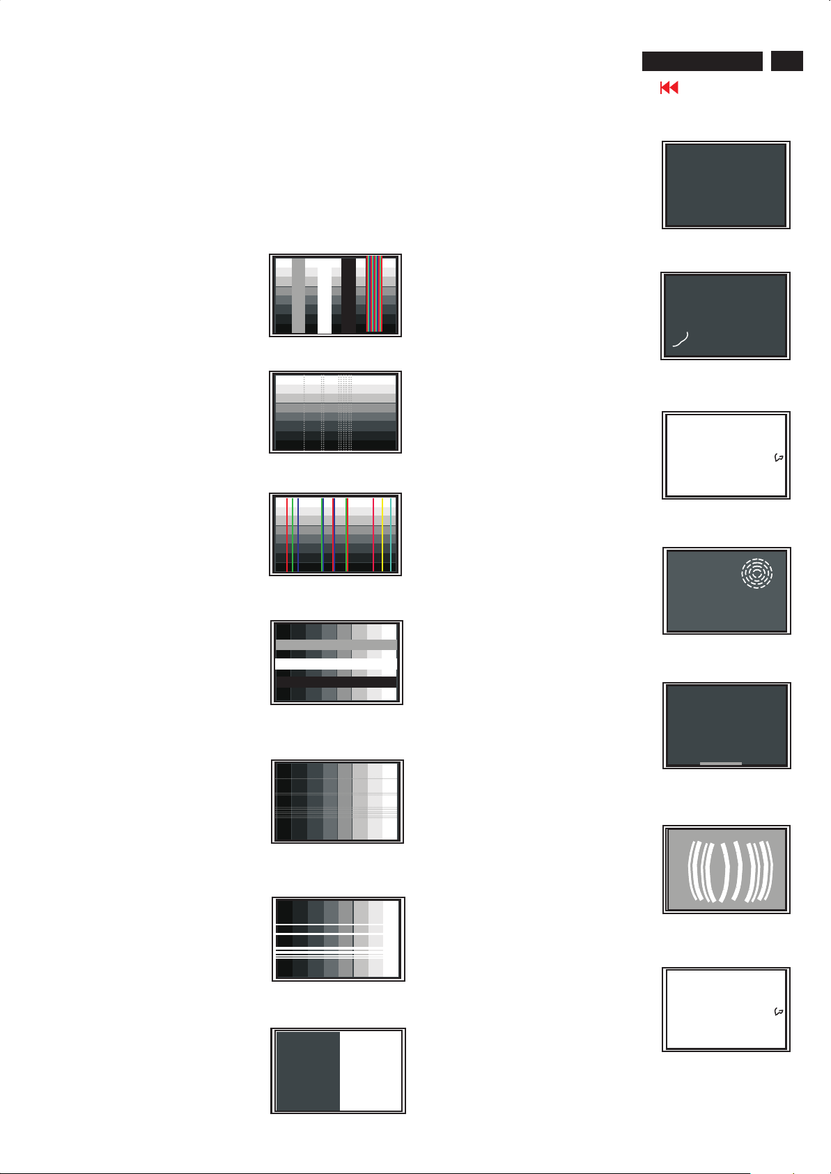
Warning Message
A warning message may appear on the screen indicating the LCD
Monitor TV current status.
When user sees this warning message, it
means that the LCD Monitor TV is in
adjustment process.
A warning message may appear on the screen
indicating that the LCD Monitor TV is out of
sync range.
Self-Test Feature Check (STFC)
Your the LCD Monitor TV when used as a computer display through
DVI and/or VGA connection provides a self-test feature that allows you
to check whether your the LCD Monitor TV is functioning properly. If
your the LCD Monitor TV and computer are properly connected but the
LCD Monitor TV screen remains dark, run the LCD Monitor TV self-test
by performing the following steps:
1. Turn off both your computer and the LCD Monitor TV.
2. Unplug the video cable from the back of the computer. To ensure
proper Self-Test operation, remove both Digital(white connector) and
the Analog(blue connector) cables from the back of computer.
3. Turn on the LCD Monitor TV.
The floating 'Philips - self-test Feature Check' dialog box should
appear on-screen (against a black background) if the LCD Monitor TV
cannot sense a video signal and is working correctly. While in self-test
mode, the power LED remains green and the self-test pattern will scroll
through the screen continually.
See Specifications for the Horizontal and
Vertical frequency ranges addressable by this
the LCD Monitor TV. Recommended mo de is
1280x 768 @ 60Hz.
This message means that there is no video
input signal.
The LCD Monitor TV is in a power saving mode
(in PC mode).
This box also appears during normal system operation if the video
cable becomes disconnected or damaged.
4. Turn off your the LCD Monitor TV and reconnect the video cable;
then turn on both your computer and the LCD Monitor TV. If your the
LCD Monitor TV screen remains blank after you use the previous
procedure, check your video controller and computer system; your
LCD Monitor TV is functioning properly.
The main OSD menu is unlocked.
The main OSD menu is locked.

Troubleshooting
Common Problems
The following table contains general information about common LCD TV problems you might encounter.
COMMON SYMPTOMS
No Video/ Power LED off
WHAT YOU EXPERIENCE
No picture, LCD TV is dead
POSSIBLE SOLUTIONS
Check connection integrity at both ends of the video cable
Electric outlet verification
Ensure power button depressed fully
300WN5
Go to cover page
19
No Video/ Power LED on
Poor Focus
Shaky/Jittery Video
Missing Pixels
Stuck-on Pixels
Brightness Problems
Geometric Distortion
No picture or no brightness
Picture is fuzzy, blurry or ghosting
Wavy picture or fine movement
LCD screen has spots
LCD screen has bright spots
Picture too dim or too bright
Screen not centered correctly
Increase brightness & contrast controls
Perform LCD TV self-test feature check
Check for bent or broken pins
Push Auto adjust button
Adjust Phase and Clock controls via OSD
Eliminate video extension cables
Perform LCD TV reset
Lower video resolution or increase font size
Push Auto Adjust button
Adjust Phase and Clock controls via OSD
Perform LCD TV reset
Check environmental factors
Relocate and test in other room
Cycle power on-off
These are pixels that are permanently off and is a natural defect that
occurs in LCD technology
Cycle power on-off
These are pixels that are permanently on and is a natural defect that
occurs in LCD technology
Perform LCD TV reset
Push Auto Adjust button
Adjust brightness & contrast controls
Note: When operating in DVI mode, the contrast adjustment is not
available.
Perform LCD TV reset on "Position Settings Only"
Push auto-adjust button
Adjust the centering controls
Ensure LCD TV is in proper video mode
Note: When operating in DVI mode, the positioning adjustments are
not available.
Horizontal/Vertical Lines
Sync Problems
LCD Scratched
Safety Related Issues
Intermittent Problems
Screen has one or more lines
Screen is scrambled or appears torn
Screen has scratches or smudges
Visible signs of smoke or sparks
LCD TV malfunctions on & off
Perform LCD TV reset
Push Auto Adjust button
Adjust Phase and Clock controls via OSD
Perform LCD TV self-test feature check and determine if these lines
are also in self-test mode
Check for bent or broken pins
Note: When operating in DVI mode, the Pixel Clock and Phase
adjustments are not available.
Perform LCD TV reset
Push Auto Adjust button
Adjust Phase and Clock controls via OSD
Perform LCD TV self-test feature check to determine if scrambled
screen appears in self-testMode
Check for bent or broken pins
Boot up in the "safe mode"
Turn LCD TV off and clean the screen
Do not perform any troubleshooting steps
LCD TV needs to be replaced
Ensure LCD TV is in proper video mode
Ensure video cable connection to computer and to the flat panel is
secure
Perform LCD TV reset
Perform LCD TV self-test feature check to determine if the
intermittent problem occurs in self-test mode

20
300WN5
Go to cover page
TV and Audio Problems
COMMON
SYMPTOMS
Poor TV signal reception
Troubleshooting
WHAT YOU EXPERIENCE POSSIBLE SOLUTIONS
Abnormal picture seen from the screen
The proximity of mountains or high buildings may be responsible for
ghost pictures, echoing or shadows. In this case, try manually
adjusting your pictures: see 'fine tuning' or adjust the direction of
the outside aerial. For Asia users in non-NTSC area: Does your
antenna enable you to receive broadcasts in this frequency range
UHF or VHF band)? In the event of difficult reception (snowy
pictures) switch the NR on the PICTURE menu to ON.
No TV picture
No sound
Video Problems
COMMON SYMPTOMS
No Video
Low Quality DVD playback
No sound
Remote Control Problems
REMOTE CONTROL
PROBLEMS
Remote control does not
work properly
Product Specific Problems
SPECIFIC SYMPTOMS
Screen image is too Small
Cannot adjust the LCD
TV with the buttons on
the front panel
No picture when TV input was selected
No sound output when a program with
sound was playing
WHAT YOU EXPERIENCE
No signal indicator is displayed.
Picture not crisp and some color
Distortion
See video but no audio
WHAT YOU EXPERIENCE
No response from LCD TV when
remote is pressed
WHAT YOU SEE
Image is centered on screen, but
does not fill entire viewing area
OSD does not appear on the screen
Have you connected the aerial socket properly? Have you chosen
the right system? Poorly connected SCART Cables or aerial
sockets are often the cause of picture or sound problems
(sometimes the connectors can become half disconnected if the
LCD TV set is moved or turned). Check all connections.
Ensure that the audio cables are firmly connected to both the audio
input connectors on your LCD TV and audio output connectors on
your PC or Video player.
If on certain TV channels you receive a picture but no sound, this
means that you do not have the correct TV system. Modify the
SYSTEM setting.
POSSIBLE SOLUTIONS
Check Video Input Selection
Composite: Yellow colored RCAjack
S-Video: Typically a round 4 pin jack
Component: Typically 3 RCA jacks of Green, Red and Blue.
Check DVD connection
Composite gives good picture
S-Video gives better picture
Component gives best picture
Check if TV volume is turn off of muted
Connect the audio cable securely
Audio cable is connected incorrectly
Verify that the audio source is selected correctly in the OSD
POSSIBLE SOLUTIONS
Point the remote control directly at the remote sensor on the LCD TV
Replace both batteries with new onesl
POSSIBLE SOLUTIONS
Perform LCD TV reset on "All Settings"
Turn the LCD TV off and unplug the power cord and then plug back
and power on
Failure Mode of LCD Panel
Quick reference for failure mode of LCD panel
This page presents problems that could be made by LCD panel. It is
not necessary to repair circuit board. Simply follow the Mechanical
instruction on this manual to eliminate failure by replace LCD panel
or backlight tubes.
Failure description Phenomenon
Polarizer has bubbles
300WN5
Go to cover page
21
..
Vertical block defect
Vertical dim lines
Vertical lines defect
(Always bright or dark
Horizontal block defect
Polarizer has bubbles
. .. .
Foreign material inside
polarizer. It shows linear or
dot shape.
)
Concentric circle formed
Horizontal dim lines
Horizontal lines defect
(Always bright or dark)
Has bright or dark pixel
Bright pixel
.
.
..
..
Dark pixel
.
.
.
.
.
.
Bottom back light of LCD is
brighter than normal
Backlight un-uniformity
Backlight has foreign material.
Black or white color, linear or
circular type
. .. .
22
300WN5
Go to cover page
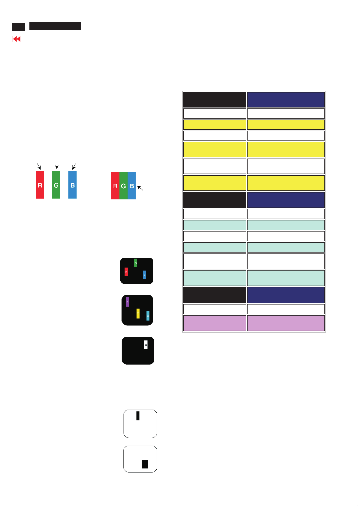
Definition of Pixel Defects
0. General
This section explains the different types of pixel defects and
defines acceptable defect levels of each type. In order to qualify
for repair or replacement under warranty, the number of pixel
defects on a TFT LCD panel must exceed these acceptable levels.
1. Definition of Pixels and Subpixels
A pixel, or picture element , is composed of three subpixels in the
primary colors of red, green and blue. Many pixels together from
an image. When all subpixels of a pixel are lit, the three colored
subpixels together appear as a single white pixel. When all are
dark, the three colored subpixels together appear as a single black
pixel. Other combinations of lit and dark subpixels appear as
single pixels of other colors.
Subpixel
Subpixel
Subpixel
Pixel
2. Types of Pixel Defects
Pixel and subpixel defects appear on the screen in different ways.
Bright dot defects
Bright dot defects appear as pixels or subpixels that are always lit
or "on"”. These are the types of bright dot defects:.
3. Pixel Defect Tolerances
In order to qualify for repair or replacement due to pixel defects
during the warranty period, a TFT LCD panel in a PHILIPS flat
panel monitor must have pixel or subpixel defects exceeding the
tolerances listed in the following tables.
BRIGHT DOT DEFECTS ACCEPTABLE LEVEL
MODEL
1 lit sub pixel 3 or fewer
2 adjacent lit sub pixels 0
3 adjacent lit sub pixels
(one white pixel)
Distance between two
bright dot defects*
Total bright dot defects of
all types
BLACK DOT DEFECTS ACCEPTABLE LEVEL
MODEL
1 dark sub pixel 5 or fewer
2 adjacent dark sub pixels 1 or fewer
3 adjacent dark sub pixels 0
300WN5
0
25 mm or more
2 or fewer
300WN5
One lit red, green or blue subpixel
Two adjacent lit subpixels:
- Red + Blue = Purple
- Red + Green = Yellow
- Green + Blue = Cyan (Light Blue)
Three adjacent lit subpixels
(One white pixel)
Black dot defects
Black dot defects appear as pixels or subpixels that are always
dark or "off"”TThese are the types of black dot defects:
One dark subpixel
Distance between two
black dot defects*
Total black dot defects of
all types
TOTAL DOT DEFECTS ACCEPTABLE LEVEL
MODEL
Total bright or black dot
defects of all types
Note: 1 or 2 adjacent subpixel defects = 1 dot defect
15 mm or more
5 or fewer
300WN5
5 or fewer
Two or three adjacent dark subpixels

Wiring Diagram
300WN5
Go to cover page
23

24
300WN5
Mechanical Instructions
Go to cover page
1. Lay LCD-TV on a flat, soft and clean surface as Fig 1.
2. Remove speakers and bases as Fig 2.
Fig 7 : Remove 1 screw
on IR PCB.
Fig 1
4. Remove back cover as Fig 8~11.
Fig 8 : Remove
4 screws
on panel.
Fig2:
Remove 8
screws.
3. Remove front bezel as Fig 3~7.
Fig 3 : Remove 3 screws
on the bottom.
Fig 4 : Remove 3 screws
on the left.
Fig 5 : Remove 3 screws
on the top.
Fig 9 : Remove 6 hex
screws.
Fig 10: Remove control
PCB.
Fig 11 : Remove 3 screws
on audio jack
PCB.
5. You can repair each board like this position as Fig 12.
Fig 6 : Remove 3 screws
on the right.
Fig 12

Mechanical Instruction
6. Remove metal frame from LCD panel as Fig 13
Fig 13 : Remove 4 screws and 3 wires.
7. Rear view on LCD panel as Fig 14.
300WN5
Go to cover page
25
Fig 14
Remark : Don't repair inverter PCB. LCD panel + inverter PCB is
a module.

26
300WN5
Display Adjustment
Go to cover page
Display Adjustment:
Press and button simultaneously for 10 secs when monitor
on normal mode. Adjust OSD menu to lower position of screen
(i.g. adjust Horizontal OSD Position and Vertical OSD Position to
0 at OSD setting sub-menu. Then press or button to move
the cursor to red words area ( see red circle on Fig 1). Press
button to access to factory mode (see Fig 2.). Please make
Menu
sure firmware version and EDID data are correct. Please do
display alignment after aging 1 hour at least.
Fig. 1
Fig. 3
2. Apply a 1280x768/60Hz signal with white pattern.Set
brightness control at 50% and contrast control at 50%. Adjust the
R.G.B gain to reach special color temperature on center of
screen.
2.1 Aim the probe CA-A30 at the center of screen as Fig. 4
2.2 Remove the lens protective cover of probe CA-A30.
2.3 Set Measuring/viewing selector to Measuring position for reset
analyzer. (Zero calibration) as Fig. 5
2.4 Turn on the colour analyzer (CA-110).
2.5 Press 0-CAL button to start reset analyzer. See Fig. 6
Fig 2. Factory menu :
cover (black)cover (black)
Measurement/viewing selectorMeasurement/viewing selector
Fig. 4
0-CAL
Fig. 6
2.6 Switch light probe to Viewing position.
2.7 Move the Lens barrel forward or backward to get clear image as
shown in Fig. 7
2.8 Switch light probe to Measuring position. It should be able to
indicate colour value on the CA-110.
Fig. 5
Clear image
PC mode WHITE-D adjustment (B)
1 Apply 1280X768/60Hz mode with 5 block pattern as Fig 3. Set
main controls brightness control at 50% and contrast to 50% on
User mode. Set color setting at natural color on User mode. Move
cursor to "AUTO-SUB" item on factory mode, press "menu" key
to active this function, then scaler will adjust SUB-CON, Offset
RGB and Color RGB automatically by it self.
Measurement/viewing selectorMeasurement/viewing selector
Fig. 7

Display Adjustment
2.9 Set color setting on normal color, blue preset and red preset on
User mode respectively and adjust Gain RGB and Sub-brightness on
factory mode to meet following specification.
PC Color Temp. Normal /sRGB Blue / 9300°K Red /5700°K
Use Minolta CA-110 for color coordinates and luminance check.
i. Luminance>380 nits in the center of the screen at Original (
Natural ) color and PC Brightness control; Contrast control at
100%
ii. Luminance =180 +/- 15 nits in the center of the screen at sRGB
colour temp. (Brightness and Contrast control set at 50% ) .
Alignment hits:
R for x value , G for y value, B and Sub-brightness for Y value on the
Colour analyzer.
2.10 Exit factory mode and User mode, then do DC on/off and AC on/of
to reset CPU.
3. After PC mode display adjustment, TV mode and HDTV mode will
be set as PC mode automatically by software.
300WN5
Go to cover page
27

28
300WN5
Go to cover page
Safety Test Requirements
All units that are returned for service or repair must pass the
original manufactures safety tests. Safety testing requires both
and testing.Hipot Ground Continuity
HI-POT TEST INSTRUCTION
1. Application requirements
1.1 All mains operated products must pass the Hi-Pot test as
described in this instruction.
1.2 This test must be performed again after the covers have
been refitted following the repair, inspection or modification
of the product.
2. Test method
2.1 Connecting conditions
2.1.1 The test specified must be applied between the parallel-
blade plug of the mainscord and all accessible metal
parts of the product.
2.1.2 Before carrying out the test, reliable conductive
connections must be ensured and thereafter be
maintained throughout the test period.
3. Equipments and Connection
3.1. Equipments
For example :
- ChenHwa 9032 PROGRAMMABLE AUTO SAFETY
TESTER
- ChenHwa 510B Digital Grounding Continuity Tester
- ChenHwa 901 (AC Hi-pot test), 902 (AC, DC Hi-pot test)
Withstanding Tester
3.2. Connection
* Turn on the power switch of monitor before Hipot and
Ground Continuity testing.
Clip
Clip
2.1.3 The mains switch(es) must be in the "ON" position.
2.2 Test Requirements
All products should be HiPot and Ground Continuity tested as
follows:
Condition HiPot Test for HiPot Test for Ground Continuity
products where products where Test requirement
the mains input the mains input is
range is Full 110V AC(USA
range(or 220V type)
AC)
Test 2820VDC 1700VDC Test current:
voltage (2000VAC) (1200VAC) 25A,AC
Test time:
Test time 3 seconds 1 second 3 seconds(min.)
(min.) Resistance
required:
Trip set at 100 uA 5 mA <=0.09+R ohm,
current for Max. R is the
(Tester) limitation; set resistance of
at 0.1 uA for the mains cord.
Min. limitation
Ramp set at 2
time seconds
(ChenHwa 9032 tester)
Video cable
Connect the "video cable"
or "grounding screw"
to the CLIP on your tester.
Grounding screw
Connect the power cord
to the monitor.
2.2.1 The test with AC voltage is only for production purpose,
Service center shall use DC voltage.
2.2.2 The minimum test duration for Quality Control Inspector
must be 1 minute. No breakdown during the test.
2.2.3 The test voltage must be maintained within the specified
voltage + 5%.
2.2.4 The grounding blade or pin of mains plug must be
conducted with accessible metal parts.
Power outlet
(Rear view of monitor)
4. Recording
Hipot and Ground Continuity testing records have to be kept for
a period of 10 years.

DDC Instructions
300WN5
Go to cover page
29
General
DDC Data Re-programming
In case the DDC data memory IC or main EEPROM which storage all
factory settings were replaced due to a defect, the serial numbers have
to be re-programmed.
It is advised to re-soldered DDC IC and main EEPROM from the old
board onto the new board if circuit board have been replaced, in this
case the DDC data does not need to be re-programmed.
Additional information
Additional information about DDC (Display Data Channel) may be
obtained from Video Electronics Standards Association (VESA).
Extended Display Identification Data(EDID) information may be also
obtained from VESA.
DDC EDID structure
For Analog interface: Standard Version 3.0
Structure Version 1.2
For Digital inferface: Standard Version 3.0
Structure Version 1.3
System and equipment requirements
1. An i486 (or above) personal computer or compatible.
2. Microsoft operation system Windows 95/98.
3. EDID301.EXE program (3138 106 10103) as shown in Fig. 1
4. A/D Alignment kits (3138 106 10079):
inclusion : a. Alignment box x1 (as Fig. 2)
Note: The alignment box has already build-in a batteries socket for
using batteries (9V) as power source. Pull out the socket by
remove four screws at the rear of box. Please do not forget that
remove batteries after programming. The energy of batteries can
only drive circuits for a short period of time.
To Printer
DC 8V~12V
Power
indicator
To Monitor
(Digital port)
A/D Alignment Kits - Digital connectionA/D Alignment Kits - Digital connection
Pin assignment
A. 15-pin D-Sub Connector
To Printer
Fig. 2Fig. 2
b. Printer cable x1
c. (D-Sub) to (D-Sub) cable x1
Note: The EDID301.EXE (Release Version 1.58 20000818)is a
windows-based program, which cannot be run in MS-DOS.
EDID301.EXE
Ver:1.58
Diskette with EDID301.EXE
DC 8V~12V
Power
indicator
A/D Alignment Kits - Analog connectionA/D Alignment Kits - Analog connection
Fig. 1Fig. 1
To Printer
To Monitor
Video Card
Video Card
1
6
11
Pin No.
B. DVI-D Connector
Assignment
1
Red video input
Green video input
2
Blue video input
3
Ground
4
No Connected
5
6
Red video ground
Green video ground
7
8
Blue video ground
1
9
17
Pin No. Assignment Pin No. Assignment
1 TMDS Data 2- 13 TMDS Data 3+
2 TMDS Data 2+ 14 +5V Power
3 TMDS Data 2/4 Shield 15 Ground (+5V)
4 TMDS Data 4- 16 Hot Plug Detect
5 TMDS Data 4+ 17 TMDS Data 06 DDC Clock 18 TMDS Data 0+
7 DDC Data 19 TMDS Data 0/5 Shield
8 No connect 20 TMDS Data 5-
9 TMDS Data 1- 21 TMDS Data 5+
10 TMDS Data 1+ 22 TMDS Clock Shield
11 TMDS Data 1/3 Shield 23 TMDS Clock+
12 TMDS Data 3- 24 TMDS Clock-
5
10
15
Pin No.
9
10
11
12
13
14
15
Assignment
+5V
Ground
Ground
Serial data line(SDA)
H.Sync
V.Sync(VCLK for DDC)
Data clock line(SCL)
8
16
24

30
300WN5
Go to cover page
1. Configuration and procedure
DDC Instructions
There are two ICs contained serial number on the circuit board,
Analog Flash ROM IC (7301), and main EEPROM (7302) which
storage all factory settings. Following descriptions are the
connection and procedure for Analog Flash ROM IC , the main
EEPROM can be re-programmed along with Analog IC by
enable factory memory data write function on the DDC
program (EDID301.EXE).
Initialize alignment box
In order to avoid that monitor entering power saving mode due to
sync will cut off by alignment box, it is necessary to initialize
alignment box before running programming software (EDID301.EXE).
Following steps show you the procedures and connection.
Step 1: Supply 8~12V DC power source to the Alignment box by
plugging a DC power cord or using batteries.
Step 2: Connecting printer cable and video cable of monitor as Fig. 1
Step 3: Run the EDID301.EXE program until the main menu appears.
This is for initialize alignment box.
PC
DC Power
8~12 V
~
~
PC
DC Power
8~12 V
~
To video card
To printer port (LTP1)
Printer
Port
~
To
Monitor
To P C
Fig. 3
D-sub
DVI to D-sub cable
D-sub video cable
DVI
2. DDC re-programming instructions
Start on DDC program
Start Microsoft Windows.
1. Insert the disk containing EDID301.EXE program into floppy disk
drive.
2. Click , choose Run at start menu of Windows 95/98.
To printer port (LTP1)
Re-programming DDC IC
Step 1: After initialize alignment box, connecting all cables and box as
Fig. 2 for analog DDC, Fig.3 for digital DDC
Step 2: Press and hold "Menu" and "Plus" buttons then power on the
monitor.
Step 3: Follow the steps on DDC re-programming instructions to staring
re-programming.
PC
To video card
To printer port (LTP1)
To
Monitor
Printer
Port
To P C
Fig. 1
DC Power
8~12 V
~
~
To
Monitor
Printer
Port
To P C
D-sub video cable
D-sub video cable
Fig. 2

DDC Instructions
300WN5
Go to cover page
31
3. At the submenu, type the letter of your computer's floppy disk drive
followed by :EDID301 (for example, A:\EDID301.exe,)
as shown in Fig. 4.
Fig. 4
4. Click button. The main menu appears (as shown on Fig. 5).
Loading DDC data from monitor
1. Click icon on the tools bar to bring up the Configuration
Setup windows as Fig.6
2. Select the DDC2B as the communication channel.
3. Enable Factory memory data write function and fill in page address
F0 to the block.
4. Disable Software DDC function.
5. Click button to confirm your selection.
Note: The Factory memory data write function will allow EDID30 to
rewrite serial numbers both Analog DDC IC and main EEPROM
to make sure both S/N are exactly the same. You may confirm the
function by checking the S/N at Product information of the OSD
menu after restarting the monitor.
Fig. 5
Note:
If the connection is improper, you will see the following error
message before entering the main menu. Meanwhile, the
(read EDID) function will be disable. At this time, please make
sure all cables are connected correctly and fixedly, and the
Command bar
Tools bar
Status bar
Fig. 6
6. Click icon to read DDC EDID data from monitor. The EDID
codes will display on screen as following. (The EDID codes are
depend on the model.) Meanwhile, The status bar will indicate
00% to 100% when reading.
Fig. 7

32
300WN5
Go to cover page
DDC Instructions
Note:
During the loading, EDID30 will verify the EDID data which just
loaded from monitor before proceed any further function, once the
data structure of EDID can not be recognized, the following error
message will appear on the screen (Fig. 8). Please confirm
following steps to avoid this message.
1. The data structure of EDID was incorrect.
2. DDC IC that you are trying to load data is empty.
3. Wrong communication channel has set at configuration setup
Windows.
4. Cables loosed or poor contact of connection.
Fig. 8
Modify DDC data (Serial No.)
1. Click icon on the toosl bar.
2. Click till the Step 7 of 9 window appears.
3. Type the new Serial No. (for example, TY 1000813).
4. Click till the last step window appears, then click to
exit the Step window.
Load DDC data from file
1. Click from the tools bar.
2. Select the file you want to open.
3. Click . Button.
4. Now you can re-programming DDC data which you just loaded
from a file, please be confirmed that model and serial number are
correct and match with the monitor you are trying to re-write.
Exit DDC program
1. Click file command on the command bar then select Exit.
Write DDC data to monitor
1. Click icon from the tools bar to starting rewrite DDC data.
2. Click for confirmation.
Save DDC data as a file
Sometimes, you maybe need to save DDC data as a text file for using
on other DDC chip. To save DDC data, follow the steps below:
1. Click icon on the tools bar and type a file name you like. The
file format is ddc type which can be open by Microsoft WordPad.
2. Click button.
Definition of Serial Number:

DDC Data
300WN5
Go to cover page
33
**********************************************************************
Analog EDID log file
********************************************************************
Vendor/Product Identification
ID Manufacturer Name : PHL
ID Product Code : 0822 (HEX.)
ID Serial Number : 1E240 (HEX.)
Week of Manufacture : 48
Year of Manufacture : 2003
EDID Version, Revision
Version : 1
Revision : 3
Basic Display Parameters/Features
Video Input Definition : Analog Video Input
0.700V/0.000V (0.70Vpp)
without Blank-to-Black Setup
Separate Sync
without Composite Sync
without Sync on Green
no Serration required
Maximum H Image Size : 64
Maximum V Image Size : 38
Display Transfer Characteristic : 2.2 (gamma)
Feature Support (DPMS) : Standby
Suspend
Active Off
Display Type : RGB color display
Color Characteristics
Red X coordinate : 0.631
Red Y coordinate : 0.339
Green X coordinate : 0.282
Green Y coordinate : 0.597
Blue X coordinate : 0.144
Blue Y coordinate : 0.076
White X coordinate : 0.284
White Y coordinate : 0.295
Established Timings
Established Timings I : 640 x 480 @60Hz (IBM,VGA)
800 x 600 @56Hz (VESA)
800 x 600 @60Hz (VESA)
Established Timings II : 1024 x 768 @60Hz (VESA)
Manufacturer's timings :
Standard Timing Identification : Unused
Detailed Timing #1
Pixel Clock (MHz) : 79.5
H Active (pixels) : 1280
H Blanking (pixels) : 384
V Active (lines) : 768
V Blanking (lines) : 30
H Sync Offset (F Porch) (pixels) : 64
H Sync Pulse Width (pixels) : 128
V Sync Offset (F Porch) (lines) : 3
V Sync Pulse Width (lines) : 7
H Image Size (mm) : 643
V Image Size (mm) : 386
H Border (pixels) : 0
V Border (lines) : 0
Flags : Non-interlaced
: Normal Display, No stereo
: Digital Separate sync.
: Positive Vertical Sync.
: Negative Horizontal Sync.
Monitor Descriptor #2
Serial Number : TY 123456
Monitor Descriptor #3
Monitor Name : Philips 300WN
Monitor Descriptor #4
Monitor Range Limits
Min. Vt rate Hz : 56
Max. Vt rate Hz : 61
Min. Horiz. rate kHz : 31
Max. Horiz. rate kHz : 63
Max. Supported Pixel : 80
No secondary GTF timing formula supported.
Extension Flag : 0
Check sum : BD (HEX.)
**********************************************************************
EDID data (128 bytes)
**********************************************************************
0: 00 1: ff 2: ff 3: ff 4: ff 5: ff 6: ff 7: 00
8: 41 9: 0c 10: 22 11: 08 12: 40 13: e2 14: 01 15: 00
16: 30 17: 0d 18: 01 19: 03 20: 68 21: 40 22: 26 23: 78
24: e8 25: b7 26: ee 27: a1 28: 56 29: 48 30: 98 31: 24
32: 13 33: 48 34: 4b 35: 23 36: 08 37: 00 38: 01 39: 01
40: 01 41: 01 42: 01 43: 01 44: 01 45: 01 46: 01 47: 01
48: 01 49: 01 50: 01 51: 01 52: 01 53: 01 54: 0e 55: 1f
56: 00 57: 80 58: 51 59: 00 60: 1e 61: 30 62: 40 63: 80
64: 37 65: 00 66: 83 67: 82 68: 21 69: 00 70: 00 71: 1c
72: 00 73: 00 74: 00 75: ff 76: 00 77: 20 78: 54 79: 59
80: 20 81: 31 82: 32 83: 33 84: 34 85: 35 86: 36 87: 0a
88: 20 89: 20 90: 00 91: 00 92: 00 93: fc 94: 00 95: 50
96: 68 97: 69 98: 6c 99: 69 100: 70 101: 73 102: 20 103: 33
104: 30 105: 30 106: 57 107: 4e 108: 00 109: 00 110: 00 111: fd
112: 00 113: 38 114: 3d 115: 1f 116: 3f 117: 08 118: 00 119: 0a
120: 20 121: 20 122: 20 123: 20 124: 20 125: 20 126: 00 127: bd

34
300WN5
Go to cover page
DDC Data
**********************************************************************
Digital EDID log file
********************************************************************
Vendor/Product Identification
ID Manufacturer Name : PHL
ID Product Code : 0822 (HEX.)
ID Serial Number : 1E240 (HEX.)
Week of Manufacture : 48
Year of Manufacture : 2003
EDID Version, Revision
Version : 1
Revision : 3
Basic Display Parameters/Features
Video Input Definition : Digital Video Input
Compatible with VESA
DFP 1.x
Maximum H Image Size : 64
Maximum V Image Size : 38
Display Transfer Characteristic : 2.2 (gamma)
Feature Support (DPMS) : Standby
Suspend
Active Off
Display Type : RGB color display
Color Characteristics
Red X coordinate : 0.631
Red Y coordinate : 0.339
Green X coordinate : 0.282
Green Y coordinate : 0.597
Blue X coordinate : 0.144
Blue Y coordinate : 0.076
White X coordinate : 0.284
White Y coordinate : 0.295
Established Timings
Established Timings I : 640 x 480 @60Hz (IBM,VGA)
800 x 600 @56Hz (VESA)
800 x 600 @60Hz (VESA)
Established Timings II : 1024 x 768 @60Hz (VESA)
Manufacturer's timings :
Standard Timing Identification : Unused
Detailed Timing #1
Pixel Clock (MHz) : 79.5
H Active (pixels) : 1280
H Blanking (pixels) : 384
V Active (lines) : 768
V Blanking (lines) : 30
H Sync Offset (F Porch) (pixels) : 64
H Sync Pulse Width (pixels) : 128
V Sync Offset (F Porch) (lines) : 3
V Sync Pulse Width (lines) : 7
H Image Size (mm) : 643
V Image Size (mm) : 386
H Border (pixels) : 0
V Border (lines) : 0
Flags : Non-interlaced
: Normal Display, No stereo
: Digital Separate sync.
: Positive Vertical Sync.
: Negative Horizontal Sync.
Monitor Descriptor #2
Serial Number : TY 123456
Monitor Descriptor #3
Monitor Name : Philips 300WN
Monitor Descriptor #4
Monitor Range Limits
Min. Vt rate Hz : 56
Max. Vt rate Hz : 61
Min. Horiz. rate kHz : 31
Max. Horiz. rate kHz : 63
Max. Supported Pixel : 80
No secondary GTF timing formula supported.
Extension Flag : 0
Check sum : BD (HEX.)
**********************************************************************
EDID data (128 bytes)
**********************************************************************
0: 00 1: ff 2: ff 3: ff 4: ff 5: ff 6: ff 7: 00
8: 41 9: 0c 10: 22 11: 08 12: 40 13: e2 14: 01 15: 00
16: 30 17: 0d 18: 01 19: 03 20: 81 21: 40 22: 26 23: 78
24: e8 25: b7 26: ee 27: a1 28: 56 29: 48 30: 98 31: 24
32: 13 33: 48 34: 4b 35: 23 36: 08 37: 00 38: 01 39: 01
40: 01 41: 01 42: 01 43: 01 44: 01 45: 01 46: 01 47: 01
48: 01 49: 01 50: 01 51: 01 52: 01 53: 01 54: 0e 55: 1f
56: 00 57: 80 58: 51 59: 00 60: 1e 61: 30 62: 40 63: 80
64: 37 65: 00 66: 83 67: 82 68: 21 69: 00 70: 00 71: 1c
72: 00 73: 00 74: 00 75: ff 76: 00 77: 20 78: 54 79: 59
80: 20 81: 31 82: 32 83: 33 84: 34 85: 35 86: 36 87: 0a
88: 20 89: 20 90: 00 91: 00 92: 00 93: fc 94: 00 95: 50
96: 68 97: 69 98: 6c 99: 69 100: 70 101: 73 102: 20 103: 33
104: 30 105: 30 106: 57 107: 4e 108: 00 109: 00 110: 00 111: fd
112: 00 113: 38 114: 3d 115: 1f 116: 3f 117: 08 118: 00 119: 0a
120: 20 121: 20 122: 20 123: 20 124: 20 125: 20 126: 00 127: a4

Repair Flow Chart
300WN5
Go to cover page
35
1.No Work / LED is off
Check if
No
power switch
is normal
Ye s
Check if AC
adaptor output
= 24V on 1102
No
and
=16V on 1103
Ye s
Try to replace
7753 CPU or 7754 CPU’s flash ROM
7752 CPU’s EEPROM or
7701 Painter or
7722 Painter’s EEPROM
Replace power switch
Replace Power board
or go to troubleshoot
power board.
3.No picture / LED is
green
Check if working voltage
3V3, 2V5, 5V to
7402 JAGASM
7753 CPU
7754 CPU’S flash ROM
7752 CPU’s EEPROM
7701 Painter
7722 Painter’s EEPROM
Yes
Check if clock source
1401 output 14MHz
1753 output 22MHz
1702 output 12MHz
Yes
Check if scaler 7402
output 48 bits TTL
RGB, clk, H/V and
DE signal
Yes
Check resistorsnetwork
3481~3486
No
No
Check circuit around each
No
No
regulator and eliminate short
and open situation
7001 pin2=5V
7008 pin3=2V5
7009 pin2=3V3
Replace 1401, 1753 or 1702
Try to replace
7753 CPU or
7754 CPU’s flash ROM
7752 CPU’s EEPROM or
7701 Painter or
7722 Painter’s EEPROM
Replace bad resistorsnetwork 3481~3486
2.No raster / Picture
too dim
Check if 1102 on
power board
Pin 1,2,3=24V
Pin4=0~4.7V
Pin5=3.3V
Ye s
Check if
inverter output =
738~1001Vrms
45K~75KHz
No
No
Check working
voltage, backlight
control signal and
brightness control
signal on scaler board
Replace LCD panel +
Inverter PCB
Ye s
Replace LVDS cable
No
Replace LCD panel
4.No D-sub picture
Check if H/V
signals input to
Schmitt trigger
7203
Ye s
Check if Schmitt
trigger 7203
output H/V signals
to JAGASM
No
No
Check input path from 1201
to 7203
Replace 7203
Ye s
Go to 3. No picture / LED is green

36
300WN5
Go to cover page
Repair Flow Chart
5.No DVI picture
Check if DVI
signals input to
TMDS-Rx 7842
Ye s
Check if DDC IC
7801 with correct
DVI EDID code
Ye s
Check if TMDSRx 7842 output 24
bits signals to
JAGASM
Ye s
Go to 3. No picture / LED is green
No
No
No
Check input path from 1801
to 7842
Put correct DVI EDID code
in 7801
Replace 7842
Ye s
Check if video
decoder 7302
output 8 bits
digital signals
Ye s
Check resistorsnetwork 3325,
3324
Ye s
Check if
VDD-IO-3V3
VDD-CORE-1V8
PLL-1V8
DAC-1V8
DAC-3V3
To FLI2300 7351
Connector 2
No
No
No
Replace 7302
Replace 3325 or 3324
Check circuit around each
regulator and eliminate short
and open situation
7006 pin3=1V8
7009 pin2=3V3
6.No TV picture
Check if tuner
1501 pin 1 output
MM-CVBS signal
Ye s
Check if connector
1601 pin 17 output
TUN-CVBS
signal
Ye s
Connector 1
Check if 7301
pin 2=3.3V
No
No
No
Replace 1501
Replace 7501
Replace 7301
Ye s
Check if 1351
output 13.5MHz
Ye s
Check if video
converter 7351
output 24 bits
YCbCr signals
Ye s
Check resistorsnetwork
3372~3377
Ye s
Go to 3. No picture / LED is green
No
Replace 1351
No
Replace 7351
No
Replace 3372~3377
Check if 1302
output 24MHz
Ye s
No
Replace 1302

7.No SVHS /
CVBS picture
Check connector 1601
Pin 20 output Y-SVHS
Pin 21 output C-SVHS
Pin 12 output AV -CVBS
signals
Repair Flow Chart
300WN5
37
Go to cover page
9.No PC / S-audio
/ CVI-audio sound
Check audio decoder 7901
Pin 35 input S-AUD-L
No
Check input path from 1642
and 1641 to 1601
Pin 36 input S-AUD-R
Pin 38 input CVI-AUD-L
Pin 39 input CVI-AUD-R
Pin 41 input PC-AUD-L
Pin 42 input PC-AUD-R
No
Check input path from 1641
and 1601to 7901
Yes
Go to connector 1
8.No HDTV picture
Check connector 1601
Pin 26 output G-Y
Pin 27 output B-Pb
Pin 25 output R-Pr
signals
Yes
Check ADC 7252
VDD=3V3
VD=3V3
PVD=3V3
Yes
Yes
Connector 3
Check if audio
decoder 7901
Pin 31=8V
Pin 10=5V
Pin 49=5V
Pin 63=5V
Yes
No
No
Check input path from 1641
to 1601
Check circuit around each
regulator and eliminate short
and open situation
Check if 1901
output 18MHz
Yes
Check if audio decoder 7901
Pin 20 output MSP-OUT-R
Pin 21 output MSP-OUT-L
signals
Yes
No
No
Eliminate short and open
situation
Replace 1901
No
Replace 7901
Check if ADC 7252
output 24 bits RGB
digital signal and
HDTV-HSYNV,
VSYNC, CLK
Yes
Check resistorsnetwork
3271~3277
Ye s
Go to connector 2
Check if TDA1517 7941
Pin 1 input V(1517 in) L
No
Replace 7252
Pin 2 input V(1517 in) R
signals
Yes
Check if 7947
Pin 7 =16V
No
Replace 3271~3277
Ye s
Check if 7947
Pin 4 output signal
Pin 6 output signal
No
No
Check circuit around
7949, 7950, 7951
Eliminate short and open
situation
No
Replace 7947
Ye s
Replace speakers

38
300WN5
Go to cover page
10.No TV sound
Repair Flow Chart
13.LED and
function key poor
Check if tuner 1501
pin 10 output 2
nd
signal
Ye s
Go to connector 3
11.No earphone
sound
Check if TDA1308
7953 pin 8=5V
Yes
Check TDA1308 7953
Pin 7 output PHONE-OUT-R
Pin 1 output PHONE-OUT-L
signals
-IF
No
No
Replace 1501
Eliminate short and open
situation
No
Replace 7953
Check circuit around
control board and
cable between
control board and
scaler board
Replace Phone Jack board
12.No remote
function
Try another remote
control
No
Check IR receiver
Yes
Ye s
Replace one good remote
control

Speakers
L/R
line out/
headphone
.
Ant
CVBS,YC,
L/R audio
YpbPr,
L/R, audio
SCART
Function Block Diagram
WXGA
Panel
LVDS
Tx
300WN5
Go to cover page
9
SDRAM
39
1 ADC for temperature
0ne I/O for CCFL detect
Audio
Amp.
Scaller board
Power board
+24V
+16V
TV Board
RS232
DVI-D
PC
audio
VGA
AC 110-220
Audio Power amp
5WX2
& earphone/
R/L audio
MSP34X0G
Sound decoder
ch
PC audio
Control key board/ RC receiver/power
LED/Power swit
R/L for YPbPr
RF IN
R/L for S/AV
TV Box
.Tuner
Line out
TDA1517
IF
nd
2
.YPbPr cinch
.S video
24 bits& CLK
DDC
.R/L cinch
Scaler
HV
MUX
HV
TMDS
SiL151
DVI-D
TNU-CVBS
Genesis JagASM
4052
HV
Analog RGB
DDC
PC IN
8 bits &CLK
Video
decoder
CVBS
-
AV
S Video
24 bits &CLK
Video
Converter
FLI2300
SAA7118A
SDTV YPbPr
SDRAM
H/V Sync
24 bit &CLK
ADC
AD 9883A
HDTV YPbPr
RGBHV
CPU
Mix+Flash
IIC
Painter I
.Teletext
Key pad
.C.C/V-chip
IR
Power sw
Inveter
YPbPr-
video&audio
IN
S-video/
AV v i d e o
& audio
IN

40
Go to cover page
9
300WN5
Power Diagram
A
B
C
D
All rights reserved. Reproduction in whole or in parts
owner.
is prohibited without the written consent of the copyright
E
F
G
H
gedeeltelijk, is niet toegestaan dan met schriftelijke
Alle rechten voorbehouden. Verveelvuldiging, geheel of
toestemming van de auteursrechthebbende.
I
J
1
A
MAIN PCB
SB: 59991 x1
PB: 59591
16V
B
3V3-STBY-ON
C
RESET-PAINTER
POW-CON-SCALER
16V
D
E
F
(1) " 000" ~ "049"
1
PAN-VCC
U160
2029
ReservedRef Des
2422026053091001
2422086110531002
SSQ7
F7A
2238586198122001
100n
50V
223858619812
100n
50V
3198021310303014
47K
212211805674
22K
243853598058
933967310685
BC848C
I18
16
1000u
9
100u
10
3V3-STBY-ON
16V
7010
LM2594M-ADJ
1
NC0
2
3043
U274
+5
3034
2017
3
4
1K
U133
1W
0R82
100n
NC1
NC2
FB
2
U132
16
3041
1K5
LM217D2T
Vin3Vout
GND
25
OUTPUT
GND
ON_OFF
U309
7008
ADJ
1
3012
Vin
620R
3011
620R
3042
200R
8
7
3039
6
5
+2V5
I27
2018
U310
100R
100u
U275
SFPJ-73V
25
11
6098
3V3-STBY
U19
5013
100u
2097
+2V5I
5006
BEAD
2011
(1)
+2V5II
5005
BEAD
2014
(2)
3045
220K
6001
BZX84-B16
U239
1
3046
I24
LM2596SX-5.0
CURRENT
SOURCE
FEEDBACK
4
3.3V , R2 = 4.2 K
12V , R2 = 21.8 K
2
3047
150K
100K
3004
47K
3003
47K
3001
47K
7001
BIAS
R1=2.5K
5V,R2=7.6K
ADJ,R2=0R
R1 = OPEN
TO ADAPTER
U159
2004
7002
BC848C
I10
8K2
3002
1.235V
REFERENCE
R2
CAPACITOR
3
5
64
7
8
2345678 9
1001
MT2
2u2
7013
BC848C
16
AMP
ACTIVE
OP AMP
I7
GM
1
2
MT1
F002
3009
2.5V
REGULATOR
F001
7003
BC848C
22K
2.5V
COMP.
GND1 MT1
3
FREQ.
150KHZ
2009
16V
3005
OSC.
100n
47K
START
UP
SHIFT
5007
BEAD
50V
5
ON
6
3006
OFF
LATCH
I25
2001
22K
I13
COMP.
CURRENT
LIMIT
COMP.
RESET
W > 4mm
1002
F7A
SSQ7
50V
100n
2026
220mV
+
DRIVER
THERMAL
LIMIT
3013
510R
+5
16V
PANEL-PWR-CTL
10u
2027
+
10u
16V
16V
1
Vin
SWITCH
I1
I20
U621
3A
OUTPUT
+5
16V
1
2
3
4
10n
2021
U73
7006
LM217D2T
Vin2Vout
ADJ
GND
1
U620
3007
+5
I16
2007
270R
5011
BEAD
1000u
S1
S2
S3
G
16
7005
SI9433DY
3
3008
620R
U235
7004
BC848C
+5
3029
2005
W > 4mm
0R
3020
U618
82K
3016
I23
2W
2R7
16
100n
3019
U338
3014
3015
47K
U12
3017
100K
47K
3018
2024
I12
470u
U134
25
2002
100n
U75
50V
1. Trace (except pin 5) both 7003 should be thick and short .
2. Keep loop area around IC very small .
3. All devices should be placed as close as possible to the IC .
I15
5001
2
6002
68uH
SS34
5002
3031
47K
+5T
2013
8
D1
U619
7
D2
6
D3
5
D4
+1V8
I9
200625470u
U633
25
100u
U161
U234
U625
2016
3022
2028
3032
+5
3037
Vin
22K
1W
0R82
100n
2W
4R7
100n
U162
3
16
U82
[R]
5003
LM217D2T
2
Vin3Vout
GND
50V
7012
BC848C
7009
LD1085D2T33
Vout
GND
ADJ
1
7011
ADJ
1
3025
620R
5K1
3024
U339
3023
160R
2009
3019 232272461007
3031 212211805678
3032
5002 313816874261
5003 313816874261
5007
7012
+3V3
2
2015
EXCEPT 1001,2006,2007,2013,2029,2097,2015,2018,2024,3022,3029,3034,3037,5001,5007,5013 WERE CHIP COMPONENTS.
12345678 9
CHN SETNAME LMT-2 ( 30" )
TYT12-
CLASS_NO
POWER
3138 158 5914
2003-12-19 3
Chuang Kevin/Debby Tai
NAME
2
3
4
5
6
7
8
300WN5BB/00
SUPERS.
CHECK
DATE
9
2003-12-19
10
14 1
C
KONINKLIJKE PHILIPS ELECTRONICS N.V. 2000
11
100u
12
I1 A4
I7 C2
I9 D5
I10 C1
I12 D4
I13 D3
I15 E4
I16 E5
I18 F7
I19 F9
A
I20 B4
I23 C4
I24 C1
I25 A3
I27 E8
U12 B4
U19 A9
U73 C5
U75 D4
25
10
10u
I19
10
10u
U81
U81 F9
U82 F6
B
1001 A2
1002 A3
2001 A3
2002 D4
2004 B1
2005 D4
2006 D5
2007 F5
2009 A2
2011 E9
2013 F5
2014 F9
C
2015 F7
2016 F6
2017 F7
2018 F8
2021 C5
2024 D4
2026 D3
2027 D3
2028 B6
2029 B7
2097 B9
3001 D1
D
3002 D1
3003 C1
3004 C1
3005 C2
3006 D3
3007 D5
3008 D5
3009 D2
3011 F8
3012 F8
3013 F3
E
3014 B4
3015 B4
3016 B4
3017 B4
3018 C4
3019 A4
3020 A4
3022 A6
3023 B6
3024 B6
3025 B7
3029 D4
F
3031 B5
3032 C6
3034 E7
3037 E6
3039 B8
3041 B8
130 A3
12
13
3042 B8
3043 C7
3045 B1
3046 B1
3047 B1
5001 F4
5002 A5
5003 A6
5005 F9
5006 E9
5007 A3
5011 F5
5013 A9
6001 D1
6002 F4
6098 B9
7001 D1
7002 D2
7003 C2
7004 C4
7005 A5
7006 D5
7008 E8
7009 E6
7010 A8
7011 A6
7012 B6
7013 B2
F001 A2
F002 B2
U132 F8
U133 E8
U134 D4
U159 B2
U160 A7
U161 A6
U162 B6
U234 B6
U235 B4
U239 E1
U274 B7
U275 A9
U309 B8
U310 B9
U338 A4
U339 B7
U618 B5
U619 A6
U620 D5
U621 B4
U625 F6
U633 E5
1
13
A
B
C
D
E
F
G
H
I
--------
J

I/O & Interface Diagram
300WN5
Go to cover page
9
41
All rights reserved. Reproduction in whole or in parts
C
D
owner.
is prohibited without the written consent of the copyright
G
H
A
B
E
14
3
5
62
12345
7
8
678
MAIN PCB
7681
TO TV_BOX BD
OUT
GND
1681
61198
1682
29
30
2728
26
25
2324
21
22
19
20
1718
1516
1314
1112
9
10
78
56
3
4
2
1
+8V
10u
2685
F100
F097
F096
F086
F092
F091
F099
F082
F093
U212
F103
3686
47K
PC-AUDIO-R
B-Pb
R-Pr
I2S-DA-OUT
C-SVHS
SDA-TV1
TUN-CVBS
MSP-INT
SCL-TV1
I2S-DA-CLK
TV-DET
16V
+5T
+5T
+5T
F104
SOUND-ENABLE
F107
MSP-OUT-L
F105
TO AUDIO BD
1684
60997
1
3
5
7
9
69086
5
4
3
2
1
F66
U222
2
4
PHONE-DET
6
F106
8
MSP-OUT-R
10
F108
F616
+5T
F69
2683
2682
330p
A
B
C
F
D
SB: 59991 x1
PB: 59591
PC-AUDIO-R
PC-AUDIO-L
3688
0R
2686
3687
0R
+8V
PC-AUDIO-L
D4-DET
G-Y
I2S-DA-IN2
I2S-DA-IN1
Y-SVHS
SC-CVI-SW
FBL-SC
ST-SC
AV-CVBS
SYNC-SC-CVI
MSP-OUT-R
MSP-OUT-L
F101
U230
F094
F085
F087
F095
U213
F098
U614
F083
F084
F080 F102
F089
U269
16V
MC78L08ACPRA
IN
E
EXCEPT 1681,1682,1684,7681 WERE CHIP COMPONENTS.
NI
6681
50
NI
330p
50
6683
3681
3683
9
+5
1K
50
330p
2681
+5
1K
50
2684
330p
3682
3684
27K
27K
10
U146
11
PC-AUDIO-L
PC-AUDIO-R
A
B
C
D
12
F66 B6
F69 B6
1681 A3
1682 A6
1684 D5
2681 B7
2682 B6
2683 D6
2684 D7
2685 E3
2686 B2
3681 B7
3682 B7
3683 C7
3684 D7
3686 C4
3687 C2
3688 C2
6681 A6
6683 C7
7681 D3
F080 C3
F082 C4
F083 C3
F084 C3
F085 B3
F086 B4
F087 B3
F089 C3
F091 B4
F092 B4
F093 C4
F094 B3
F095 B3
F096 B4
F097 B4
F098 B3
F099 B4
F100 B4
F101 A3
F102 C4
F103 D4
F104 D5
F105 E5
F106 E6
F107 E4
F108 E6
F616 B6
U146 D8
U212 C4
U213 B3
U222 D6
U230 B3
U269 C3
U614 C3
E
13
A
B
C
D
E
F
G
H
gedeeltelijk, is niet toegestaan dan met schriftelijke
Alle rechten voorbehouden. Verveelvuldiging, geheel of
toestemming van de auteursrechthebbende.
I
J
(5) "681" ~ "699"
1
123
Ref Des BASIC
1681
2685 NOT USED 222224119876
2686 NOT USED
3687 212211805631
0R
3688 212211805631
0R
7681
NOT USED
2 9
NAFTA
823827713901NOT USED
61198
10u
223886715181
NOT USED NOT USED NOT USED
NOT USED
933539650686
MC78L08ACPRA
3
823827713901
61198
222224119876
10u
223886715181
933539650686
MC78L08ACPRA
4 11
WEVIDEO
823827713901
61198
222224119876
10u
223886715181
NOT USEDNOT USED
933539650686
MC78L08ACPRA
5
456
TYT12-
CLASS_NO
I /O & INTERFACE
32003-12-19
Chuang Kevin/Debby Tai
NAME
6
7
8
300WN5BB/00
78
LMT-2 ( 30" )SETNAMECHN
3138 158 5914
SUPERS.
DATECHECK
2003-12-19
C
KONINKLIJKE PHILIPS ELECTRONICS N.V. 2000
10
130
12
I
1
--------
J
214
A3
13

42
Go to cover page
9
300WN5
Video Decoder Diagram
A
B
C
D
All rights reserved. Reproduction in whole or in parts
is prohibited without the written consent of the copyright
owner.
E
F
G
H
gedeeltelijk, is niet toegestaan dan met schriftelijke
Alle rechten voorbehouden. Verveelvuldiging, geheel of
toestemming van de auteursrechthebbende.
I
J
A
B
C
D
E
F
(6) "301" ~ "349"
C-"301" ~ "340"
2
123
MAIN PCB
SB: 59991 x1
PB: 59591
U367
SYNC-SC-CVI
TUN-CVBS
AV-CVBS
G-Y
FB-G
Y-SVHS
B-Pb
FB-B
C-SVHS
R-Pr
FB-R
FB
3303
0R
3304
0R
123
Ref Des AP NAFTA
3303 NOT USED
3304 212211805631
0R
NOT USED 212211805631
212211805631
0R
* Delete this page for basic model
234
2304
47n
2302
47n
2301
47n
2308
47n
2306
47n
2307
47n
2309
47n
2305
47n
2303
47n
2311
47n
2314
47n
2315
47n
2312
47n
2313
47n
3305
470R
3
4
5
6
7
456789
+3V3
Vin
3307
100R
3332
47R
2316
7301
LM1117MPX-3.3
MT1
3
ADJ
I334
47n
2317
51
4
GND
1
47n
2319
2
U121
U326
I350
Vout
I301
II303
47n
4
2326
2318
10u
I314
47n
5304
BEAD
10
N10
M10
M13
L10
N5
P4
K1
K2
K3
C2
G4
G3
H2
H1
E3
G1
B1
D2
D1
E1
D3
P3
M1
N8
P8
M7
P7
N7
M6
P6
N6
J2
L3
J3
F2
F3
F1
L2
L7
L6
I328
RTCO
RTS1
RTS0
LLC2
LLC
AI11
AI12
AI13
AI14
AI1D
AGND
AI21
AI22
AI23
AI24
AI2D
AI31
AI32
AI33
AI34
AI3D
AGNDA
AI41
AI42
AI43
AI44
AI4D
EXMCLR
AOUT
ADP0
ADP1
ADP2
ADP3
ADP4
ADP5
ADP6
ADP7
ADP8
CLKEXT
FSW
M2
10u
2329
100n
2327
100n
L1
D4
VDDA4
VDDA1A
I327
J1
G2
VDDA2A
VDDA3A
5301
E2
C8
VDDI1
VDDA4A
BEAD
F12
C10
VDDI2
VDDI3
2323
100n
2328
100n
J12
VDDI4
VDDI5
M5
2321
H4
M3
VDDA2
VDDA0K4VDDA1
F4
VDDA3
SAA7118E/V1
VSSI1
VSSI2
VSSI3
VSSA3C1VSSA4
VSSA0J4VSSA1H3VSSA2
E4
VSSI4L5VSSI5L9VSSI6
VSSE1
VSSE2
VSSE3
VSSE4L4VSSE5L8VSSE6
D5
D7
F11
D10
D9
J11
D11
G11
56789
NAME
7
U130
II302
U67
U68
U312
U313
U314
U315
U316
U317
U366
U318
U324
II304
WE
0R
NOT USED
+5
VS-OSD
LLC2
I330
8
5302
BEAD
I315
I332
2324
100n
2333
100n
C5
M9
VDDI6
M4
D12
H12
VDDE5M8VDDE6
VDDE1C9VDDE2
VDDE3
VDDE4
7302
RES1
RES2
VXSS
VSSE7
B2
A4
L11
B13
B14
TYT12-
CLASS_NO
Chuang Kevin/Debby Tai
U124
BEAD
RES3
C3
5303
B3
M11
VXDD
VDDE7
RES4C4RES5
C12
2331
100n
2332
100n
B5
A5
TDI
TDO
RES6
RES7N1RES8N2RES9
C13
B6
C6
TCK
TRSTN
N3
D6
TMS
RES10
RES11
N13
I326
4K7
3313
P12
P11
M12
AMCLK
ALRCLK
AMXCLK
RES12P2RES13
A2
N14
I322
VIDEO DECODER
32003-12-19
300WN5BB/00
CHECK
P10
N11
SDA
ASCLK
XTOUT
XTAL
A3
B4
6C24500043
24M576HZ
2334
SUPERS.
DATE
9108
XTALI
15p
N9
SCL
P13
1302
50
U122
P9
N4
CE
INT_A
TEST1
TEST0
C14
D13
2003-12-19
U126
P5
RESON
TEST2
TEST3
A13
B12
2335
LMT-2 ( 30" )SETNAMECHN
XTRI
XRV
XRH
XRDY
XDQ
XCLK
XPD0
XPD1
XPD2
XPD3
XPD4
XPD5
XPD6
XPD7
HPD0
HPD1
HPD2
HPD3
HPD4
HPD5
HPD6
HPD7
ITRI
IGP1
IGP0
IGPV
IGPH
ITRDY
IDQ
ICLK
IDP0
IDP1
IDP2
IDP3
IDP4
IDP5
IDP6
IDP7
TEST4
A12
I321
TEST5
50
15p
B11
D8
C7
A6
B7
A7
A8
B8
A9
B9
A10
B10
A11
C11
D14
E11
E13
E12
E14
F13
F14
G13
L12
K13
L14
K14
K12
N12
L13
M14
G14
G12
H11
H14
H13
J14
J13
K11
3314
3K3
109
I317
U354
+3V3
3316
47R
3315
I319
U125
U127
U123
II305
I333
47R
U248
U128
U247
U129
11
3318
100R
3317
100R
3319
100R
I318
100R
3322
I335
3321
U246
U311
47R
3325
47R
1
R
2
R
3
R
45
R
3324
47R
R
1
R
2
R
3
R
45
3326
47R
8
7
6
8
7
6
INT-SCALER
DA-VSYNC
II301
I302
DA-DATA0
I303
DA-DATA1
I304
DA-DATA2
I305
DA-DATA3
I306
DA-DATA4
I307
DA-DATA5
I308
DA-DATA6
I309
DA-DATA7
I310
121
SDA-TV1
SCL-TV1
DA-HSYNC
HS-OSD
DA-CLK
DA-FID
A
B
C
D
E
F
3138 158 5914
314
C
KONINKLIJKE PHILIPS ELECTRONICS N.V. 2000
116
12
U67 C2
U68 D2
1302 E7
2301 C2
2302 C2
2303 E2
2304 B2
2305 E2
2306 D2
2307 D2
2308 C2
2309 D2
2311 E2
2312 F2
2313 F2
2314 E2
2315 F2
2316 F3
2317 F3
2318 F4
2319 F4
2321 A5
2323 A6
2324 A6
2326 A4
2327 A5
2328 A6
2329 A5
2331 A6
2332 A6
2333 A6
2334 F7
2335 F7
3303 B1
3304 C2
3305 F2
3307 B3
3313 A7
3314 A8
3315 B8
3316 B8
3317 A9
3318 A9
3319 A9
3321 B9
3322 B9
3324 D9
3325 C9
3326 D9
3332 B3
5301 A5
5302 A6
5303 A6
5304 A4
7301 A4
7302 C6
I301 D4
I302 C9
I303 C9
I304 C9
I305 C9
I306 D9
I307 D9
I308 D9
I309 D9
I310 D9
I314 F4
I315 A6
I317 A8
I318 B8
I319 B8
I321 E8
I322 E7
I326 A7
I327 A5
I328 A5
I330 D3
I332 A6
I333 B8
I334 B3
I335 B8
I350 A4
II301 B9
1
13
13
II302 C2
II303 E4
II304 F2
II305 B8
U121 B4
U122 A7
U123 D8
U124 A7
U125 C8
U126 A7
U127 C8
U128 D8
U129 D8
U130 C2
U246 C8
U247 C8
U248 C8
U311 D8
U312 D2
U313 D2
U314 E2
U315 E2
U316 E2
U317 E2
U318 F2
U324 F2
U326 F4
U354 A8
U366 B2
U367 B2
--------
A
B
C
D
E
F
G
H
I
J
A3130

Scaler Diagram
300WN5
Go to cover page
9
43
All rights reserved. Reproduction in whole or in parts
Alle rechten voorbehouden. Verveelvuldiging, geheel of
is prohibited without the written consent of the copyright
gedeeltelijk, is niet toegestaan dan met schriftelijke
owner.
toestemming van de auteursrechthebbende.
A
B
A
C
B
D
E
C
F
D
G
E
H
I
F
J
G
K
L
H
M
N
O
P
(8) "401 ~ "469"
1
2
123
MAIN PCB
SB: 59991 x1
PB: 59591
+3V3_ASM
+3V3
5401
100MHZ
10u
2427
100n
2422
2423
U478
5402
100MHZ
+2V5
100MHZ
+2V5
5405
+2V5II
3401
+2V5II
3402
I
2431
100n
2432
10u
2437
2436
10R
U477
10u
2442
2443
U481
10R
U485
2445
5408
100MHZ
U475
+2V5I
3410
3435
2405
+2V5I
2402
100n
2424
100n
(2)
100n
100n
2441
10u
2444
ReservedRef Des
2238867151092464
319802132240
319802190030
U1
100n
2408
100n
2409
100n
1n
1n
(1)
100n
U505
+2V5
U484
(2)
u113
100n
(1)
+2V5I
100n
2403
2401
+3V3_ASM
10u
2421
100n
2426
100MHZ
+2V5
5403
1n
2428
100MHZ
u457
5404
10u
100n
2434
2435
+2V5
100MHZ
+2V5I
U483
100MHZ
+3V3
5407
100n
10u
10R
3403
2447
U474
+2V5I
U476
150R
3404
2448
1 2345
1
2
3
4
5
6 1412
87
9
10
11
133
15
16
17
45678910111213 14
TO POWER BOARD
F41
F40
3
2
4
1
1402-A
U482
+3V3
3422
220R
U605
U550
SD1
SD0
AE22
AD22
SDD0
SDD1
PWM1_GPIO1
MCAD5
MCAD6
MCAD7
MCAD8
A3
B3
C3
MCAD6
MCAD7
MCA8
U547
U554
U660
3410
+3V3
4K7
+5
3432
+3V3
10K
3429
U518
U258
U517
U501
U545
U500
SD7
SD2
SD4
SD6
SD5
SD3
AE24
AE23
AC24
AD24
AC23
AD23
SDD7
SDD5
SDD6
SDD4
SDD2
SDD3
MCAD9
MCALE
MCCS#
MCRD#
MCWR#
A2
E3
E4
D3
C4
JWR#
JRD#
MCALE
MCA9
U552
U551
EXCEPT 1402 WERE CHIP COMPONENTS.
XOUT
PA21
FDE
FVSYNC
FHSYNC
FSHFCLK
PANEL-PWR-CTL
U149
U172
U105
5
6
7
8
R
R
R
AF20
PDE
PARHS_PADE
F1
HDTV-SOG
4
AE21
AC21
PVSYNC
PHSYNC
MCAD0
B6
MCAD0
3417
U638
3
U651
AD21
PENVDD
B5
MCAD1
10K
AF22
PENBKL
MCAD2
MCAD1
C5
MCAD2
R
2
1
U150
T-MISSION
E2
B1
PWM0_GPO0_SCDT
MCAD3
MCAD4
A4
B4
D5
MCAD3
MCAD4
MCAD5
5412
100MHZ
3424 100R
u460
U171
47R
3428
22R
u404
A1
C2
AF12
AC13
HSOUT
PNLCLK
CMPOUT
PSHFCLK
PA22
PA23
PACLK
PAVSYNC
PAHSYNC
F2
G1
G2
G4
G3
PA23
PA22
HDTV-VSYNC
HDTV-HSYNC
TMDS-CLK
U284
10p
2463
FG2
AD16
A14
PD10
G2N
100n
2417
100n
2411
100n
2413
(NI)
2464
U238
FG3
AE16
A19
PD11
U479
U243
U237
U245
U244
U242
FB4
FB5
FB0
FB6
FB1
FB2
FB3
FB7
SR0
SR1
SR2
SR3
SR4
AE20
PD23
IREFH
C13
AF5
C12
PD24
IREFL
0u1
SR6
SR7
SR5
SG0
SG1
AF7
AF6
AE7
AE6
AD7
AC7
AD6
AC6
PD30
PD29
PD32
PD28
PD31
PD27
PD26
PD25
XIN
PA03
PA04
PA00
PA01
PA02
A6
P1
P2
N3
N2
M1
PA01
PA02
PA03
PA04
PA05
PA00
100R
3405
U637
4
16
100n
6N14300113
1401
FG4
FG5
FG6
FG7
AF17
AF18
AE17
AD17
PD12
PD13
B2P
B2N
A18
AE19
AE18
AC18
AD20
AD18
AD19
AC19
PD14
PD15
I1
A8
A9
PD22
PD21
PD16
PD17
PD20
PD19
PD18
RREFL
RREFH
GREFH
GREFL
I2
BREFH
BREFL
C14
C15
C17
C16
C19
C18
(1)
+3V3
5411
U473
2452
U480
SB0
PD34
SB1
SG4
SG5
SG6
SG7
SG3
AF9
AE9
AD9
AC9
AE10
AD10
AC10
PD36
PD35
PD37
PD40
PD39
PD38
PD41
PA06
PA07
PA08
PA09
PA10
PA11
PA12
PA13
L1
L2
L3
L4
K2
K3
M4
PA07
PA08
PA09
PA10
PA11
PA12
PA13
U286
3
OUT
2
OSC
GND
CONT
1
SG2
AE8
AD8
PD33
PA05
M2
M3
PA06
VDD
U419
SB3
SB4
SB2
SB5
SB6
SB7
3427
U115
A7
AF11
AE11
AE12
AD12
AD11
AC12
PD43
PD46
PD42
PD45
PD44
PD47
PA19
PA20
PA18
PA17
PA16
PA15
PA14
J4
J3
J2
J1
K4
H1
H2
H3
PA14
PA15
PA16
PA17
PA18
PA19
PA20
PA21
100n
2407
100n
2415
100n
2404
VDD22
A5
VDD21
K1
VDD20
AA1
VDD19
A26
VDD18
J26
VDD17
N26
VDD16
U26
VDD15
Y26
100n
2425
VDD14
AF26
VDD13
AF21
VDD12
AF16
VDD11
AF10
VDD10
H4
VDD9
R4
VDD8
AB4
VDD7
D23
100n
2429
VDD6
K23
VDD5
T23
VDD4
AB23
VDD3
D21
VDD2
AC20
VDD1
AC14
VDD0
AC8
U613
VDDP2
C22
VDDP1
B22
PVDD1
D20
GPVDD
C21
5406
D17
GVDD2
D15
RVDD2
D13
IVDD2
D11
BVDD1
D18
100n
2439
GVDD1
D16
RVDD1
D14
IVDD1
D12
XVDD
D7
AVDD4
C9
AVDD3
C8
CVDD2
D8
CVDD1
D9
DVDD
D10
AVDD2
C11
AVDD1
C10
SVDD
D19
1n
2446
(1)
u452
1n
10u
2449
(1)
2416
BVDD2
FR0
AD13
PD00
100n
FR1
AE13
A13
REDP
U2
PD01
100n
2414
100n
2412
FR2
FR3
FR4
FR6
FR7
FR5
FG0
FG1
AF15
AF14
AE15
AE14
AD15
AC15
AD14
AC16
PD06
PD05
PD07
PD03
PD02
R1P
R1N
A12
REDN
U116
PD04
G1P
G1N
A17
A16
GREENP
GREENN
U569
B1P
A21
BLUEP
U568
B1N
A20
BLUEN
U567
PD09
PD08
R2P
G2P
R2N
A11
A15
A10
U566
6 7 8 9 10111213 14
F42
5
SD9
SD8
AF24
AC25
SDD8
SDD9
MCRESET#
MCINT
E1
D2
RESET#
MCINT-ASM
U553
U652
3431
3435
(NI)
U496
SD10
AD25
D1
U328
F43
6
7
16V
4K7
(NI)
BC848C
U392
U612
3434
U549U509
U497
U498
SD14
SD15
SD11
SD12
SD13
AF25
AE25
AE26
AB24
AD26
SDD13
SDD12
SDD11
SDD14
SDD10
7402
JAGASM-A4
TEST
PB00
PB01
PB02
Y1
Y2
AA2
AA3
B-U-OUT0
B-U-OUT1
B-U-OUT2
B-U-OUT3
10K
3409
8
7403
U31
SD16
AB25
SDD16
SDD15
PB03
Y3
B-U-OUT4
9
2462
10u
10
47K
3433
47K
SD17
AB26
SDD17
PB04
PB05
W1
B-U-OUT5
10
100n
SD19
SD18
AA24
AA23
SDD19
SDD18
PB07
PB06
W3
W2
B-U-OUT6
B-U-OUT7
2461
SD20
AA25
SDD20
PB08
W4
G-Y-OUT0
SD21
AA26
SDD21
PB09
V1
G-Y-OUT1
50V
SD22
Y23
SDD22
PB10
V2
G-Y-OUT2
U511
SD23
Y24
SDD23
PB11
V3
G-Y-OUT3
U510
SD24
Y25
SDD24
PB12
V4
G-Y-OUT4
SD25
W24
SDD25
PB13
U1
G-Y-OUT5
U508
SD26
W25
SDD26
PB14
U2
G-Y-OUT6
SD27
W26
SDD27
PB15
U3
G-Y-OUT7
SD28
L23
SDD28
PB16
U4
R-V-OUT0
U519
SD29
L24
SDD29
PB17
T1
R-V-OUT1
SD30
L25
SDD30
PB18
T2
R-V-OUT2
SD31
K24
SDD31
PB19
T3
R-V-OUT3
SD32
K25
SDD32
PB20
T4
R-V-OUT4
U502
SD33
K26
SDD33
PB21
R1
R-V-OUT5
U515
SD34
J23
SDD34
PB22
R2
R-V-OUT6
U514
SD35
J24
SDD35
PB23
R3
R-V-OUT7
SD36
J25
U499
SDD36
U548
SD37
H23
SDD37
PBCLK
P4
U512
U491
SD40
SD39
SD38
SD41
H24
H25
H26
G24
SDD38
SDD39
SDD40
SDD41
PBHSYNC
PBRHS_PBDE
PBVSYNC
P3
C6
D6
VGA-TMDS-VS
VGA-TMDS-DE
TMDS-HS
SD42
G25
SDD42
PC00
AF1
U327
U503
SD43
G26
SDD43
PC01
AF2
U513
SD44
F23
SDD44
PC02
AF3
SD45
F24
SDD45
PC03
AF4
U504
SD46
F25
SDD46
PC04
AE1
SD47
E23
SDD47
PC05
AE2
3437
0R05
U455
U646
U516
SD49
SD48
E25
E24
SDD49
SDD48
PC07
PC06
AE4
AE3
CLASS_NO
TSCAS#
U494
SD50
E26
SDD50
PC08
AD1
U64
5
R
4
U493
SD51
D24
SDD51
PC09
AD2
TSWE#
SD52
D25
SDD52
PC10
AD3
TYT12-
U456
6
R
3
SD53
D26
SDD53
AD4
TSRAS#
U492
SD54
C23
SDD54
PC12
PC11
AC1
U608
7
R
2
U649
U495
SD55
C24
SDD55
PC13
AC2
TSCKE#
8
R
1
SD57
SD56
C25
C26
SDD56
PC14
AC4
AC3
U546
SDD57
PC15
U458
47R
3412
SD58
B23
SDD58
TSCLK
SD59
SD60
B24
B25
SDD59
SDD60
PCHSYNC
PCCLK
AB3
AA4
HS-S23
CLK-S23
2465
SD61
B26
SDD61
PCHREF
AB2
U459
U609
BA1
5
6
R
R
4
3
U645
5p6
SD62
SD63
A25
A24
SDD63
SDD62
PCVSYNC
PCVREF_GPIO2
PCFIELD_GPIO3
AB1
AE5
AD5
VS-S23
INT-SCALER
U463
U461
U462 U467
TSDQM
7
8
47R
R
R
3411
2
1
U643
22R
MEMCLK
3416
U668
T24
P24
P23
R25
R23
SDWE#
SDCKO
SDRAS#
SDCAS#
SDCKON
PLLCLKOUT_GPIO4
SVSS
SCLK
SDATA
F3
F4
B7
B19
U221
U223
U626
LMT-2 ( 30" )SETNAMECHN
TSA0
R24
SDCKE
MEMCLK
AVSS1
XSVSS
C20
5
R
4
AVSS2
C7
TSBA#
T26
B2
TSA1
6
R
3
T25
SDCKFB
IVSS1
B14
B12
10K
3406
10K
3407
10K
3408
U464
RVSS1
TSA2
M26
SDCS0#
GVSS1
B16
7
R
2
M24
B18
U465
BANK
BVSS1
TSA3
M23
8
47R
R
3414
1
U489
U490
U506
U507
V23
M25
DQS
DQM
SDA0
IVSS2
DVSS
RVSS2
B11
B10
B13
+3V3
+3V3
+3V3
SCALER
300WN5BB/00
NAME
5
6
7
8
9
10
11
12
13
14
32003-12-19
Chuang Kevin/Debby Tai
CHECK
15
SUPERS.
DATE
164
2003-12-19
17
18
U468
U488
V24
SDA1
GVSS2
B15
V25
B17
5
R
4
V26
SDA2
BVSS2
U466
TSA4
U23
SDA3
B9
6
R
3
U24
SDA4
CVSS1
B8
TSA5
U25
SDA5
CVSS2
SDA6
7
R
2
P25
B20
TSA6
P26
SDA7
PVSS1
A22
SDA8
VSSP1
8
R
1
U486
U487
N24
SDA9
GPVSS
B21
U469
47R
3413
U639
N25
SDA10
VSSP2
D22
3138 158 5914
C
KONINKLIJKE PHILIPS ELECTRONICS N.V. 2000
18
TSA7
VSS56
VSS55
VSS54
VSS53
VSS52
VSS51
VSS50
VSS49
VSS48
VSS47
VSS46
VSS45
VSS44
VSS43
VSS42
VSS41
VSS40
VSS39
VSS38
VSS37
VSS36
VSS35
VSS34
VSS33
VSS32
VSS31
VSS30
VSS29
VSS28
VSS27
VSS26
VSS25
VSS24
VSS23
VSS22
VSS21
VSS20
VSS19
VSS18
VSS17
VSS16
VSS15
VSS14
VSS13
VSS12
VSS11
VSS10
VSS9
VSS8
VSS7
VSS6
VSS5
VSS4
VSS3
VSS2
VSS1
VSS0
U1 B2
U2 I3
F40 A8
F41 A8
F42 A8
F43 A9
U31 C9
U64 A11
1401 I5
1402-A A7
2401 C2
2402 C1
2403 C2
2404 C2
2405 B1
2407 B2
2408 B2
2409 B2
2411 B4
2412 B3
2413 B4
2414 B3
2415 B2
2416 B3
2417 B4
2421 E2
2422 E1
2423 E1
2424 E1
2425 E2
2426 E2
2427 E1
2428 E2
2429 E2
2431 F1
2432 F1
2434 F2
2435 F2
2436 F1
2437 F1
2439 G2
2441 G1
2442 G1
2443 G1
2444 H1
2445 H1
2446 H2
2447 H2
2448 I2
2449 I2
2452 I4
2461 A9
2462 A9
2463 B6
2464 B6
2465 B12
3401 F1
3402 H1
3403 H2
3404 I2
3405 I5
3406 I13
3407 I13
3408 I13
3409 I8
3410 B8
3411 B12
3412 B12
3413 B14
3414 B13
3415 B14
3416 C12
3417 I7
3422 B7
3424 B7
3427 C6
3428 C7
3429 C8
3431 A8
3432 B8
3433 B9
3434 C9
3435 B8
3437 H11
5401 B1
5402 E1
5403 E2
5404 F2
5405 F1
5406 F2
5407 G2
5408 H1
5411 I4
5412 B7
7402 F9
7403 B9
U105 B7
U115 D6
U116 I3
U149 B7
U150 C7
U171 B7
U172 B7
U221 I13
U223 I13
U237 C5
U238 C4
U242 C4
U243 C4
U244 C4
U245 C4
U258 C8
U284 A6
U286 I6
U327 H11
U328 I8
U392 B8
20
U419 C6
U455 A11
U456 A11
U458 A12
U459 A12
U461 A12
U462 A13
U463 A13
U464 A13
U465 A13
U466 A14
U467 A14
U468 A14
U469 A14
U470 A14
U471 A14
U472 A14
U473 I4
U474 H2
U475 H1
U476 H2
U477 G1
U478 E1
U479 I4
U480 I4
U481 G1
U482 A7
U483 G2
U484 F2
U485 H1
U486 B14
U487 B14
U488 B13
U489 B13
U490 B13
U491 C10
U492 C11
U493 C11
U494 C11
U495 C12
U496 C8
U497 C8
U498 C8
U499 C10
U500 C8
U501 C8
U502 C10
U503 C11
U504 C11
U505 E2
U506 C13
U507 D13
U508 C9
U509 C7
U510 C9
U511 C9
U512 C10
U513 C11
U514 C10
U515 C10
U516 C11
U517 C8
U518 C8
U519 C10
U545 C8
U546 C12
U547 I7
U548 C10
U549 C9
U550 C8
U551 I8
U552 I8
U553 I8
U554 I8
U566 I3
U567 I3
U568 I3
U569 I3
U605 C7
U608 A12
U609 A12
U612 B8
U613 F3
U626 I13
U637 I5
U638 I7
U639 B14
U642 B14
U643 B12
U645 B12
U646 B11
U649 B11
U651 B7
U652 A8
U660 A8
U668 D12
u113 H2
u404 C7
u452 I3
u457 F2
u460 B7
A
B
C
D
E
F
G
H
I
J
K
L
M
N
19
U470
U472
U471
TSA8
TSA9
A
TSA10
5
6
7
8
R
4
47R
R
R
R
3415
3
2
1
U642
B
C
D
E
F
G
H
AC11
AC17
AC22
AF13
AF19
AF23
AC26
T16
T15
T14
T13
T12
T11
R16
R15
R14
R13
R12
R11
P16
P15
P14
P13
P12
P11
N16
N15
N14
N13
N12
N11
M16
M15
M14
M13
M12
M11
L16
L15
L14
L13
L12
L11
W23
N23
G23
Y4
N4
D4
AF8
R26
L26
F26
A23
AC5
N1
C1
I
O
1
--------
P
414
19
A2130
20

44
Go to cover page
9
300WN5
LVDS Tx Diagram
A
B
C
D
All rights reserved. Reproduction in whole or in parts
owner.
is prohibited without the written consent of the copyright
E
F
G
H
gedeeltelijk, is niet toegestaan dan met schriftelijke
toestemming van de auteursrechthebbende.
Alle rechten voorbehouden. Verveelvuldiging, geheel of
I
J
1
A
B
C
D
E
F
"491"~"499"
R- "481"~"499"
3
4
52
6
7
8
9
10
11
123456789
MAIN PCB
SB: 59991 x1
PB: 59591
10u
3488
10R
U24
+3V3
2492
10u
3489
10R
+3PLL
2493
U92
10u
U33
NI
FR0
FR1
FR2
FR3
FR4
FR5
FR6
FR7
FG0
FG1
FG2
FG3
FG4
FG5
FG6
FG7
FB0
FB1
FB2
FB3
FB4
FB5
FB6
FB7
U259
U255
U254
U253
U252
U251
U655
U657
U174
U658
U169
U164
U167
100R3482
45
R
3
R
R
2
R
1
3481
100R
R
45
R
3
R
2
R
1
100R3484
45
R
3
R
2
R
1
R
100R
3483
R
45
R
3
R
2
R
1
100R
3486
R
45
R
3
R
2
R
1
100R
3485
R
4
R
3
R
2
R
1
U34
U635
6
U636
7
U640
8
U357
U641
6
U644
7
U647
8
U163
6
U331
7
U356
8
U173
U330
6
U168
7
U648
8
U650
U653
6
U654
7
U186
8
U325
5
U165
6
U329
7
U166
8
+3LVDS
B0
B1
U5
B2
B3
B4
B5
B6
B7
G0
G1
G2
G3
G4
G5
G6
G7
R0
R1
R2
R3
R4
R5
R6
R7
2495
12345
Ref Des
Reserved
2122118056313492
0R
U32
2494 100n
U189
3491
3492
U191
0R
0R
+3V3
R1
R7
G2
G3
G4
G0
G1
G5
G6
G7
B2
B0
B1
B3
B4
B5
B6
B7
FHSYNC
FVSYNC
5491
BLM21
U256
3487
1
2
3
4
5
6
7
8
9
10
11
12
13
14
15
16
17
18
19
20
21
22
23
24
25
26
27
28
10K
7491
THC63LVDM83A
Vcc0
TD1
TA5
TA6
GND0
TB0
TB1
TD2
Vcc1
TD3
TB2
TB3
GND1
TB4
TB5
TD4
R_F
TD5
TB6
TC0
GND2
TC1
TC2
TC3
TD6
Vcc2
TC4
TC5
TO PANEL
2499
1
2
3
4
5
6
7
8
9
10
11
12
13
14
15
16
17
18
19
20
100n
50
1491
63622
U117
TA4
TA3
TA2
GND4
TA1
TA0
TD0
LVDSGND2
TA+
TB+
LVDSVcc
LVDSGND1
TC+
TCLK-
TCLK+
TD+
LVDSGND0
PLLGND1
PLLVcc
PLLGND0
PDWN
CLKIN
TC6
GND3
TA-
TB-
TC-
TD-
3493
CLK-
CLK+
U628
10K
FSHFCLK
FDE
R6
R5
R4
R3
R2
R0
0-
+3LVDS
0+
1-
1+
5494
BLM21
U187
2-
2+
3-
3+
+3V3
100n
+3PLL
5496
2496
BLM21
2497
100n
U10
U11
U13
U14
U18
U22
U15
PAN-VCC
U17
U6
U8
0-
U9
0+
1-
1+
2-
2+
CLK-
CLK+
3-
5495
321611
3+
56
55
54
53
52
51
50
49
48
47
46
45
44
43
42
41
40
39
38
37
36
35
34
33
U188
32
31
30
U190
29
6789
TYT12-
CLASS_NO
LMT-2 ( 30" )SETNAMECHN
LVDS TX
3138 158 5914
300WN5BB/00
32003-12-19
NAME
Chuang Kevin/Debby Tai
2
3
4
5
61
7
8
SUPERS.
DATECHECK
2003-12-19
10
C
KONINKLIJKE PHILIPS ELECTRONICS N.V. 2000
11
A
B
C
D
E
F
12
12
U5 B3
U6 B8
U8 B8
U9 B8
U10 C8
U11 C8
U13 C8
U14 C8
U15 D8
U17 E8
U18 D8
U22 D8
U24 A3
U32 A4
U33 D4
U34 A2
U92 B4
1491 B9
2492 B4
2493 B4
2494 B4
2495 B3
2496 D7
2497 E7
2499 E9
3481 C2
3482 B2
3483 D2
3484 D2
3485 F2
3486 E2
3487 F5
3488 B3
3489 B4
3491 D4
3492 D4
3493 E7
5491 A5
5494 C7
5495 D8
5496 E7
7491 A6
U117 D9
U163 C2
U164 E2
U165 E2
U166 F2
U167 F2
U168 D3
U169 D2
U173 D3
U174 C2
U186 E2
U187 C8
U188 E7
U189 C4
U190 E7
U191 A5
U251 B2
U252 B2
U253 B2
U254 B2
U255 B2
U256 E5
U259 A2
U325 E2
U329 F2
U330 D3
U331 C2
U356 C2
U357 B2
U628 E7
U635 B2
U636 B2
514
U640 B2
U641 B2
U644 B2
U647 C2
U648 D3
U650 E3
U653 E3
U654 E3
U655 C2
U657 C2
U658 D2
1
13
A
B
C
D
E
F
G
H
I
--------
J
A3130
139

SDRAM Diagram
300WN5
Go to cover page
9
45
All rights reserved. Reproduction in whole or in parts
C
D
owner.
is prohibited without the written consent of the copyright
G
A
B
E
2491
NI
U600
U601
U409
U410
U411
U415
U412
12
A
B
C
D
E
U3 B3
U4 B3
U88 B8
2008 B6
2010 B9
2019 B7
2471 B2
2472 B1
2474 B2
2475 B2
2477 B2
2478 B1
2480 B6
2481 B6
2483 B5
2484 B6
2485 B4
2486 B4
2487 B4
2489 B9
2490 B7
2491 B9
5471 A7
5472 A8
5473 B3
5474 B3
7471 D3
7472 D8
U143 C5
U394 C5
U395 C5
U396 C5
U397 D5
U398 D5
U399 E5
U400 E5
U405 E5
U409 D9
U410 D9
U411 E9
U412 E9
U415 E9
U600 C9
U601 C9
13
A
B
C
D
E
F
G
1
2
3
4
12
5
34 78
7
56
86
910
11
9
MAIN PCB
SB: 59991 x1
A
B
C
D
F
E
2472
PB: 59591
2478
100n
100n
2474
TSA0
TSA1
TSA2
TSA3
TSA4
TSA5
TSA6
TSA7
TSA8
TSA9
TSA10
TSBA#
BA1
TSCKE#
TSCLK
TSRAS#
TSCAS#
TSWE#
TSDQM
100n
2477
100n
2471
2019
NI
A0
A1
A2
A3
A4
A5
A6
A7
A8
A9
A10_AP
NC0
NC1
NC2
NC3
NC4
NC5
NC6
BA0
BA1
CS
CKE
CLK
RAS
CAS
WE
DQM0
DQM1
DQM2
DQM3
NI
+3V3
BEAD
5471
U88
3
VDDQ09VDDQ135VDDQ241VDDQ349VDDQ455VDDQ575VDDQ681VDDQ7
7472
VSSQ012VSSQ132VSSQ238VSSQ346VSSQ452VSSQ578VSSQ684VSSQ7
6
81
VSSQ678VSSQ7
84
+3V3
5474
43
VDD01VDD115VDD229VDD3
VSS044VSS158VSS272VSS3
86
BEAD
DQ10
DQ11
DQ12
DQ13
DQ14
DQ15
DQ16
DQ17
DQ18
DQ19
DQ20
DQ21
DQ22
DQ23
DQ24
DQ25
DQ26
DQ27
DQ28
DQ29
DQ30
DQ31
DQ0
DQ1
DQ2
DQ3
DQ4
DQ5
DQ6
DQ7
DQ8
DQ9
2487
2
4
5
7
8
10
11
13
74
76
77
79
80
82
83
85
31
33
34
36
37
39
40
42
45
47
48
50
51
53
54
56
100n
2486
100n
SD0
SD1
SD2
SD3
SD4
SD5
SD6
SD7
SD8
SD9
SD10
SD11
SD12
SD13
SD14
SD15
SD16
SD17
SD18
SD19
SD20
SD21
SD22
SD23
SD24
SD25
SD26
SD27
SD28
SD29
SD30
SD31
2485
U143
100n
U394
U395
U396
U397
U398
U399
U400
U405
2483
NI
2480
NI
2481
NI
2484
NI
TSA0
TSA1
TSA2
TSA3
TSA4
TSA5
TSA6
TSA7
TSA8
TSA9
TSA10
TSBA#
BA1
TSCKE#
TSCLK
TSRAS#
TSCAS#
TSWE#
TSDQM
2008
NI
2490
NI
25
26
27
60
61
62
63
64
65
66
24
14
21
30
57
69
70
73
22
23
20
67
68
19
18
17
16
71
28
59
+3V3
5473
BEAD
U3 U4
100n
2475
100n
9
25
A0
26
A1
27
A2
60
A3
61
A4
62
A5
63
A6
64
A7
65
A8
66
A9
24
A10_AP
14
NC0
21
NC1
30
NC2
57
NC3
69
NC4
70
NC5
73
NC6
22
BA0
23
BA1
20
CS
67
CKE
68
CLK
19
RAS
18
CAS
17
WE
16
DQM0
71
DQM1
28
DQM2
59
DQM3
VDDQ235VDDQ341VDDQ449VDDQ555VDDQ675VDDQ7
VDDQ03VDDQ1
7471
K4S643232E-TC50
VSSQ06VSSQ112VSSQ232VSSQ338VSSQ446VSSQ5
52
+3V3
NI
5472
1
VDD015VDD129VDD243VDD3
VSS058VSS172VSS286VSS3
44
BEAD
DQ10
DQ11
DQ12
DQ13
DQ14
DQ15
DQ16
DQ17
DQ18
DQ19
DQ20
DQ21
DQ22
DQ23
DQ24
DQ25
DQ26
DQ27
DQ28
DQ29
DQ30
DQ31
DQ0
DQ1
DQ2
DQ3
DQ4
DQ5
DQ6
DQ7
DQ8
DQ9
2010
2489
NI
NI
2
4
5
7
8
10
11
13
74
76
77
79
80
82
83
85
31
33
34
36
37
39
40
42
45
47
48
50
51
53
54
56
SD32
SD33
SD34
SD35
SD36
SD37
SD38
SD39
SD40
SD41
SD42
SD43
SD44
SD45
SD46
SD47
SD48
SD49
SD50
SD51
SD52
SD53
SD54
SD55
SD56
SD57
SD58
SD59
SD60
SD61
SD62
SD63
H
gedeeltelijk, is niet toegestaan dan met schriftelijke
Alle rechten voorbehouden. Verveelvuldiging, geheel of
toestemming van de auteursrechthebbende.
I
J
F
(9) "471" ~ "475"
C -"471" ~ "495"
1
123
Ref Des Reserved
2008 223878615649
2010 223878615649
2019 223878615649
2480 223878615649
2481 223878615649
2483 223878615649
2484 223878615649
2489 223878615649
2490 223878615649
2491
223878615649
5471
313816874261
5472
313816874261
932217603668
7472
2
3
4
5
45
CHN SETNAME LMT-2 ( 30" )
CLASS_NO
2003-12-19 3
NAME
6 12
7
F
6789
TYT12-
SDRAM
3138 158 5914
300WN5BB/00
Chuang Kevin/Debby Tai
CHECK DATE
8
SUPERS.
9
2003-12-19
10
14 6
C
KONINKLIJKE PHILIPS ELECTRONICS N.V. 2000
11
130
1
H
I
--------
J
A3
13

46
Go to cover page
9
300WN5
PC_Analog In Diagram
A
B
C
D
All rights reserved. Reproduction in whole or in parts
is prohibited without the written consent of the copyright
owner.
E
F
G
H
gedeeltelijk, is niet toegestaan dan met schriftelijke
Alle rechten voorbehouden. Verveelvuldiging, geheel of
toestemming van de auteursrechthebbende.
I
J
1
A
B
C
D
E
F
(3) "201" ~ "250"
1
2
3
4
58
1234
MAIN PCB
SB: 59991 x1
PB: 59591
3239
DDC-SCL
0R
3230
0R
U435
3201
U276
3202
12
14
15
11
10
DDCSCL
DDCSCL
RXD
DDC-SDA
DDCSDA
U241
TXD
+3V3
DDCCTL
123
Reserved
Ref Des
222224119876
2209
2221 223878615649
3201 319802134720
319802134730
3202
933714830653
7201
2
DDC5V
6
1
16
VDD
7202
M24C02
E0
E1
E2
SCL
WC_
VSS
U53
VEE
8
2221
Zx
Zy
DDC5V
8
VCC
7
VSS
13
SDA
U433
DDC5V
U434
3
PC-HSYNC
2206
100n
5
DDCSDA
4
DDC5V
PC-VSYNC
7206
LM810M3X-4.0
VCC
GND
3
1
+5
RESET
2203
DDC-SCL
10K
3211
10K
3212
DDC-SDA
3213
220R
22p
2209
U334
2
U52
3203
0R
2204
U112
22p
2205
U663
U50
U573
3207
3214
220R
3205
100n
74LVC14APW-T
4M7
7201
X0
X1
X2
X3
1
Y0
5
Y1
2
Y2
4
Y3
A
9
B
INH
2
3
6
U51
7
456
4
5
2K2
6
U49
6
7
9
10
11
56789
F27
F22
100R
3215
3216
100R
I239
5203
100MHZ
100MHZ5204
2K2
3206
7203
1
3
5
9
11
13
F21
+3V3
14
VCC
2
U572
4
6
8
10
12
GND
7
EXCEPT 1201 WERE CHIP COMPONENTS.
F26
F20
3208
100R
U110
3209
U257
U111
0R
F25
16
11
12
13
14
10
15
17
F24
PC-HSYNC-ASM
PC-VSYNC-ASM
RESET#
RESET
1201
6
1
7
2
8
3
9
4
5
U268
3231
100R
VGA-S-TEST
F28
F210
F29
3221
150R
3217
3218
3222
U574
2215
75R
75R
75R
5201
100MHZ
5202
100MHZ
5205
100MHZ
6211
BAS32L
100n
U571
U337
U58
U570
+2V5I
U436
2208
1u
2211
1u
2213
1u
5206
0u1
3234
7K5
U336
U335
3235
3236
U56
180K
U437
3K9
3238
2218
180K
2u2
3237
3223
100R
180K
3225
100R
3224
100R
2202
2212
2214
3226
150R
5p6
3228
0R
5p6
3227
0R
5p6
3229
0R
U236
BAS32L
789
TYT12-
CLASS_NO
LMT-2 ( 30" )SETNAMECHN
PC - ANALOG IN
3138 158 5914
32003-12-19
NAME
Chuang Kevin/Debby Tai
7
8
300WN5BB/00
SUPERS.
DATECHECK
2003-12-19
9
10
C
KONINKLIJKE PHILIPS ELECTRONICS N.V. 2000
113
6212
REDP
REDN
GREENP
GREENN
BLUEP
BLUEN
DDC5V
12
F20 B5
F21 C5
F22 B5
F24 C6
F25 B6
F26 B6
F27 B7
F28 B7
F29 C7
U49 C5
A
U50 E4
U51 E2
U52 D4
U53 E2
U56 B8
U58 C7
1201 B6
2202 B9
2203 C4
2204 C4
2205 D4
2206 E3
B
2208 B8
2209 E4
2211 B8
2212 C9
2213 C8
2214 C9
2215 D7
2218 F8
2221 A2
3201 C1
3202 D1
C
3203 F4
3205 C4
3206 C5
3207 F4
3208 E5
3209 E6
3211 B4
3212 B4
3213 C4
3214 C4
3215 B5
3216 B5
D
3217 B7
3218 C7
E
F
3221 D7
3222 C7
3223 B9
3224 C9
3225 B9
3226 D9
3227 C9
3228 B9
3229 D9
3230 B1
3231 C6
3234 E8
3235 E8
3236 F8
3237 E8
3238 E8
3239 A1
5201 B7
5202 B7
5203 C5
5204 C5
5205 C7
5206 D8
6211 D7
6212 D9
7201 A2
7202 E2
7203 D5
+5
13
7206 E3
F210 C7
I239 B5
U110 E5
U111 D 6
U112 E4
U236 D9
U241 C1
U257 F5
U268 C6
U276 C1
U334 E4
U335 C8
U336 B8
U337 B7
U433 B3
U434 B3
U435 E1
U436 E7
U437 E8
U570 D7
U571 B7
U572 D5
U573 E4
U574 D7
U663 E4
--------
1
A
B
C
D
E
F
G
H
I
J
714
12
A3130
13

Scaler_Up Diagram
300WN5
Go to cover page
9
47
A
B
C
D
All rights reserved. Reproduction in whole or in parts
is prohibited without the written consent of the copyright
owner.
E
F
G
H
gedeeltelijk, is niet toegestaan dan met schriftelijke
Alle rechten voorbehouden. Verveelvuldiging, geheel of
toestemming van de auteursrechthebbende.
I
A
B
C
D
E
F
MCA0
MCA1
MCA2
MCA3
MCA4
MCA5
MCA6
MCA7
MCA8
MCA9
MCA10
MCA11
MCA12
MCA13
MCA14
MCA15
MCA16
MCA17
MCA0
MCA1
MCA2
MCA3
MCA4
MCA5
MCA6
MCA7
12
A
B
C
D
E
F
U71 C8
1751 B3
1752 C3
1753 A4
2751 A9
2752 A6
2753 A4
2754 B4
2755 C9
2757 E3
3751 D3
3752 C4
3753 C4
3754 D4
3755 D4
3756 D4
3757 D5
3758 F7
3759 F7
3761 B4
3762 C4
3763 E4
3764 B4
3765 F9
3766 B3
3767 A4
3768 C4
3769 D4
3771 B3
3772 B3
5751 C2
5752 D2
7751 A9
7752 A1
7753 C6
7754 D8
7755 E2
F751 B3
F752 B3
F753 B2
F754 B2
F755 C3
F756 C3
I771 D4
I773 C4
U109 C4
U204 D2
U240 D4
U391 D9
U420 A4
U421 B5
U422 B4
U423 C5
U424 C4
U425 D4
U426 D4
U427 D5
U428 E5
U429 A7
U430 B7
U431 B7
U432 B7
U453 F3
U454 F1
U520 C7
U521 C7
U522 D7
U523 C5
U524 F7
U525 D9
U526 D9
U527 D7
U528 D7
13
U529 D7
U530 E9
U531 E9
U532 E9
U533 D7
U534 E7
U535 C5
U536 C5
U537 C7
U538 A4
U543 D7
U555 B4
U575 C7
U576 D9
U577 D9
A
B
C
D
E
F
G
H
TO RS232 BD
JFE6338V
F753
F754
+3V3
+5
2757
100n
U453
1751
1752
MCWR#
4
58
6
345
U420
NI
MCA14
MCA15
JWR#
3V3-STBY
1
2
3
4
5
4
3
2
1
F756
3751
4K7
3771
F755
F751
0R
+5
+5
+5
+5
FXXX
IICSCL
16V
3772
0R
F752
+5
MEMCLK
U422
3764
10K
4K73766
I773
+5
SDA-1
3768
4K7
U424
U425
3769
4K7
I771
U426
RESET-PAINTER
RESET
DDCCTL
VGA-S-TEST
INT-FLI
3763
4K7
DVI-S-TEST
U538
MCINT-ASM
TV-IRQ
WP-S
SOFT-RESET
3752
IICSDA
U109
MCA16
MCA17
SCL-1
DDC-SCL
DDC-SDA
3756
0R
3755
0R05
2753
15p
NI
3767
100R
2754
15p
U555
4K7
U240
3761
3762
0R
3753
3754
1753
0R
U423
100R
100R
3757
U421
U523
U535
0R
U428
22M1184HZ
U536
U427
21
20
11
13
14
15
16
17
2
3
4
5
6
7
8
9
35
10
23
34
1
12
XTAL1
XTAL2
P3.0_RxD0
P3.1_TxD0
P3.2_INT0
P3.3_INT1
P3.4_T0
P3.5_T1
P1.0_T2
P1.1_T2EX
P1.2
P1.3
P1.4
P1.5
P1.6_SCL
P1.7_SDA
EA
RESET
P4.0_PWM0
P4.1_PWM1
P4.2_PWM2
P4.3_PWM3
3V3-UP
MX10E8050XQC
7
VDD1
7753
VSS1
10
11
6789
2751
100n
20
VCC
7751
GND
10
2755
10u
10
32
16
3V3-UP
A10
A11
A12
A13
A14
A15
A16
A17
2
Q0
5
Q1
6
Q2
9
Q3
12
Q4
15
Q5
16
Q6
19
Q7
U526
12
A0
U576
11
A1
U525
10
A2
U577
9
A3
U391
8
A4
7
A5
6
A6
5
A7
27
A8
26
A9
U532
23
25
U530
4
U531
28
29
3
2
30
3765
4K7
I_O0
I_O1
I_O2
I_O3
I_O4
I_O5
I_O6
I_O7
RESET
OE
WE
CE
3V3-UP
11
LE
1
OE
74LVC373APW-T
3
D0
4
D1
7
D2
8
D3
13
D4
14
D5
17
D6
18
D7
3V3-UP
U71
VCC
7754
AT49LV002NT-90JC
VSS
2752
10u
10
44
P3.7_RD
P3.6_WR
ALE
PSEN
P2.0_A8
P2.1_A9
P2.2_A10
P2.3_A11
P2.4_A12
P2.5_A13
P2.6_A14
P2.7_A15
P0.0_AD0
P0.1_AD1
P0.2_AD2
P0.3_AD3
P0.4_AD4
P0.5_AD5
P0.6_AD6
P0.7_AD7
22
U429
U430
U431
U432
3V3-UP
PSEN#
3V3-UP
MCWR#
MCRD#
MCWR#
MCALE
PSEN#
MCA8
MCA9
MCA10
MCA11
MCA12
MCA13
MCA14
MCA15
MCAD0
MCAD1
MCAD2
MCAD3
MCAD4
MCAD5
MCAD6
MCAD7
NI
19
18
33
32
24
25
26
U575
27
U537
28
29
U520
30
U521
31
43
42
41
40
39
38
37
36
3758
10K
3759
0R
U543
U522
U529
U533
U527
U528
U534
U524
MCALE
MCAD0
MCAD1
MCAD2
MCAD3
MCAD4
MCAD5
MCAD6
MCAD7
13
14
15
17
18
19
20
21
1
24
31
22
1
2
3 9
21
MAIN PCB
SB: 59991 x1
PB: 59591
VCC
SCL
SDA
WC
8
7
6
5
5751
BEAD
5752
BEAD
1
2
3
4
5
6
7
8
+5
WP-S
IICSCL
IICSDA
3V3-UP
7755
74LVC139PW-T
1E
1A0
1A1
1Y0
1Y1
1Y2
1Y3
U204
VCC
2A0
2A1
2Y0
2Y1
2Y2
2Y3GND
RXD
TXD
RESET
3V3-UP
16
15
2E
14
13
12
11
10
9
7752
M24C16-WBN6
1
E0
2
E1
3
E2
4
VSS
+3V3
3V3-STBY
MCRD#
MCA14
MCA15
U454
JRD#
EXCEPT 1751,1752,7752 WERE CHIP COMPONENTS.
I
123456789
J
"751" ~ "799"
1
CHN SETNAME LMT-2 ( 30" )
TYT12-
CLASS_NO
1
--------
SCALER_UP
3138 158 5914
J
300WN5BB/00
2003-12-19 3
NAME
Chuang Kevin/Debby Tai
CHECK DATE
2
3
4
5
6
7
8
SUPERS.
9
2003-12-19
10
14 8
C
KONINKLIJKE PHILIPS ELECTRONICS N.V. 2000
11
130 A3
12
13

48
Go to cover page
9
300WN5
Video Converter Diagram
A
B
C
D
E
F
G
H
K
All rights reserved. Reproduction in whole or in parts
is prohibited without the written consent of the copyright
owner.
L
M
N
gedeeltelijk, is niet toegestaan dan met schriftelijke
toestemming van de auteursrechthebbende.
Alle rechten voorbehouden. Verveelvuldiging, geheel of
O
P
I
J
"351" ~ "399"
C -"341" ~ "399"
2383
U26
47R 3372
R
R
R
R
R
R
R
R
R
R
R
R
47R 3374
R
R
R
R
47R
47R 3376
R
R
R
R
R
R
R
R
14
15
16
11 12 13
+3V3
5355
100MHZ
U438
U439
100n
2387
100n
100n
2385
2386
100n
2384
100n
I354
ADDR0
I356
ADDR1
I358
ADDR2
ADDR3
ADDR4
ADDR5
U368
ADDR6
U369
ADDR7
ADDR8
U393
ADDR9
I370
ADDR10
I371
U444
+3V3
3381
22R
U443
U542
U380
1
B-U-OUT0
U381
2
B-U-OUT1
U389
3
B-U-OUT2
U382
45
B-U-OUT3
337347R
3375
337747R
1
2
3
45
1
2
3
45
1
2
3
45
1
2
3
45
1
2
3
45
B-U-OUT4
B-U-OUT5
B-U-OUT6
B-U-OUT7
R-V-OUT0
R-V-OUT1
R-V-OUT2
R-V-OUT3
R-V-OUT4
R-V-OUT5
R-V-OUT6
R-V-OUT7
G-Y-OUT0
G-Y-OUT1
G-Y-OUT2
G-Y-OUT3
G-Y-OUT4
G-Y-OUT5
G-Y-OUT6
G-Y-OUT7
U383
U390
U384
U385
U379
U378
U377
U376
U372
U373
U374
U375
U349
U662
U386
U351
U606
2388
100n
U539
3382
4K7
U104
U442
U25
+1V8
100MHZ
+1V8
100MHZ
+3V3
100MHZ
U441
5352
5354
100n
2389
75
55
49
41
35
VDDQ6
VDDQ5
VDDQ4
VDDQ3
VDDQ2
7352
HY57V643220CT-6
VSSQ6
VSSQ5
VSSQ4
VSSQ3
VSSQ2
78
52
46
38
32
100n
2345
100n
2342
81
VDDQ7
84
100n
VSSQ7
100n
1
15
VDD0
VDD1
VSS0
58
44
U27
2347
9
3
25
A0
26
A1
VDDQ1
VDDQ0
27
A2
60
A3
61
A4
62
A5
63
A6
64
A7
65
A8
66
A9
24
A10_AP
14
NC0
21
NC1
30
NC2
57
NC3
69
NC4
70
NC5
73
NC6
22
BA0
23
BA1
20
CS
67
CKE
68
CLK
19
RAS
18
CAS
17
WE
16
DQM0
71
DQM1
28
DQM2
59
DQM3
VSSQ1
VSSQ0
6
12
DAC-1V8
U388
100n
2396
PLL-1V8
5353
10u
2395
2397
DAC-3V3
U387
2346
11 12 13 14
TYT12-
CLASS_NO
LMT-2 ( 30" )SETNAMECHN
VIDEO_CONVERTER
300WN5BB/00
14
NAME
Chuang Kevin/Debby Tai
32003-12-19
CHECK
154
SUPERS.
DATE
16
2003-12-19
VSS1
2343
17
+3V3
5356
100MHZ
29
43
DQ0
VDD2
VDD3
DQ1
DQ2
DQ3
DQ4
DQ5
DQ6
DQ7
DQ8
DQ9
DQ10
DQ11
DQ12
DQ13
DQ14
DQ15
DQ16
DQ17
DQ18
DQ19
DQ20
DQ21
DQ22
DQ23
DQ24
DQ25
DQ26
DQ27
DQ28
DQ29
DQ30
DQ31
VSS2
VSS3
U107
86
72
100n
100n
2338
18
14
100n
2392
2
4
5
7
8
10
11
13
74
76
77
79
80
82
83
85
31
33
34
36
37
39
40
42
45
47
48
50
51
53
54
56
100n
2394
100n
2393
DATA0
DATA1
DATA2
DATA3
DATA4
DATA5
DATA6
DATA7
U446
U447
DATA9
DATA10
DATA11
U450
DATA12
DATA13
DATA14
DATA15
DATA16
U370
DATA17
DATA18
DATA19
DATA20
DATA21
DATA22
DATA23
DATA24
DATA25
DATA26
U350
DATA27
U359
DATA28
U360
DATA29
DATA30
DATA31
100n
2339
100n
U445
U659
U632
U656
U448
U451
U607
U449
U440
U371
U541
G
19
A
B
C
D
E
F
H
TP1 A6
U107 E13
U25 E12
U108 I7
U131 A7
U26 D10
U135 A7
U27 G13
U210 A5
U28 H1
U29 G7
U220 A7
U30 H6
U340 A7
U36 E7
U341 E10
U38 D8
U343 E10
U39 D8
U344 E10
1351 G2
U345 F10
2338 I13
U346 G10
2339 I14
U349 H11
2342 I13
U350 D14
U351 I11
2343 I13
U352 H6
2345 H13
U353 H6
2346 I12
2347 H13
U358 F10
U359 D14
2352 H1
U360 D14
2353 H1
U361 H6
2354 H2
U368 B11
2355 H2
U369 B11
2356 G2
U370 C14
2357 H2
U371 C14
2358 G3
U372 H11
2359 H3
2361 I1
U373 H11
2362 I1
U374 H11
2363 I2
U375 H11
2364 I2
U376 G11
2365 I2
U377 G11
2366 H3
U378 G11
U379 G11
2367 H3
U380 E11
2368 H3
U381 E11
2369 H4
U382 F11
2371 I3
U383 F11
2372 I3
U384 F11
2373 I3
U385 F11
2374 I3
U386 I11
2375 H6
U387 I12
2376 H6
U388 F12
2377 H7
2378 I7
U389 F11
2379 H7
U390 F11
2382 A10
U393 B11
2383 A10
U406 A8
U407 A8
2384 A11
U408 A8
2385 A11
U413 A8
2386 A11
U438 A12
2387 A11
U439 A13
2388 A12
U440 B14
2389 A12
U441 E12
2392 A13
U442 E12
2393 A14
U443 D11
2394 A14
U444 C11
2395 H12
U445 B14
2396 G12
U446 B14
2397 H12
U447 C14
3350 D2
3351 B1
U448 C14
3352 D2
U449 C14
3353 D2
U450 C14
U451 C14
3354 E2
U539 D12
3355 B1
U540 E2
3356 E2
3357 E2
U541 C14
3358 D2
U542 E11
3361 G1
U556 B8
3362 G1
U557 C8
3363 G1
U558 C9
3364 G2
U559 C8
3365 H6
U560 C8
3366 I6
U561 C9
3368 G8
U562 C8
3369 H3
U563 C8
3371 E8
U564 D8
3372 E10
U565 D8
3373 F10
U578 E2
U579 E2
3374 G10
U580 E2
3375 H10
U581 E2
3376 H10
3377 I10
U606 I11
3381 D11
U607 C14
3382 D11
U632 C14
3384 A7
U656 D14
U659 B14
3385 A7
3388 I6
U662 H11
3389 I6
U664 G10
3391 I6
3393 A7
5351 H1
5352 F12
5353 H12
5354 I12
5355 A12
5356 A13
5357 I1
7351 D5
7352 C13
I354 B11
I356 B11
I358 B11
I370 B11
I371 C11
I395 H7
I396 I1
II345 G2
I
II346 G2
II347 H7
II366 E9
II377 H10
II388 H10
II399 I10
U103 A7
U104 D12
U106 H5
A
B
C
D
E
F
G
H
I
J
K
L
M
N
O
1
--------
3138 158 5914
P
A2130
20
17
C
KONINKLIJKE PHILIPS ELECTRONICS N.V.2000
18
19
914
168
171
DAC_VDD
DAC_AVDDB
DAC_PVSS
DAC_VSS
DAC_AVSSB
169
172
U352
174
DAC_AVDDG
DAC_AVSSG
175
2376
2375
3388
177
DAC_AVDDR
DAC_AVSSR
178
DAC-3V3
186
183
DAC_AVDD
DAC_GR_AVDD
DAC_AVSS
185
184
U353
8
187
DAC_PVDD
DAC_GR_AVSS
U30
3389
TP1
DAC_BOUT
170
U361
116
117
TEST_OUT0
TEST_OUT1
DAC_ROUT
DAC_GOUT
176
173
3391
U131
118
119
120
CTLOUT0
CTLOUT1
CTLOUT2
DAC_VREFOUT
DAC_RSET
DAC_COMP
181
180
179
II347
3365
U108
3366
962
10
11
12 204
13
78910
INT-FLI
0R
0R
0R
CLKOUT
2379
U340
HS-S23
U135
VS-S23
U103
U413
DATA0
50
DATA1
51
52
53
54
55
56
57
58
59
60
61
64
65
66
67
70
71
72
73
74
75
76
77
78
79
82
83
84
85
86
87
91
92
93
94
95
98
99
100
101
102
103
104
105
106
107
108
109
110
111
114
U36
125
126
127
130
131
132
133
134
135
136
137
140
141
142
143
144
145
148
149
150
151
152
153
154
155
156
OE
U29
3368
4K7
U407
DATA2
DATA3
DATA4
DATA5
DATA6
DATA7
DATA8
DATA9
DATA10
DATA11
DATA12
DATA13
DATA14
DATA15
DATA16
DATA17
DATA18 DATA8
DATA19
DATA20
DATA21
DATA22
DATA23
DATA24
DATA25
DATA26
DATA27
DATA28
DATA29
DATA30
DATA31
ADDR10
ADDR9
ADDR8
ADDR7
ADDR6
ADDR5
ADDR4
ADDR3
ADDR2
ADDR1
ADDR0
3371
22R
DAC-3V3
U556
U560
U565
U406
U408
U557
U559
U558
U561
U562
U563
U38
U39
U564
II366
CLK-S23
U344
U341
U343
U358
U345
U346
U664
II377
II388
II399
U220
121
122
SDRAM_DATA_0
SDRAM_DATA_1
CTLOUT3
CTLOUT4
SDRAM_DATA_2
SDRAM_DATA_3
SDRAM_DATA_4
SDRAM_DATA_5
SDRAM_DATA_6
SDRAM_DATA_7
SDRAM_DATA_8
SDRAM_DATA_9
SDRAM_DATA_10
SDRAM_DATA_11
SDRAM_DATA_12
SDRAM_DATA_13
SDRAM_DATA_14
SDRAM_DATA_15
SDRAM_DATA_16
SDRAM_DATA_17
SDRAM_DATA_18
SDRAM_DATA_19
SDRAM_DATA_20
SDRAM_DATA_21
SDRAM_DATA_22
SDRAM_DATA_23
SDRAM_DATA_24
SDRAM_DATA_25
SDRAM_DATA_26
SDRAM_DATA_27
SDRAM_DATA_28
SDRAM_DATA_29
SDRAM_DATA_30
SDRAM_DATA_31
SDRAM_ADDR10
SDRAM_ADDR9
SDRAM_ADDR8
SDRAM_ADDR7
SDRAM_ADDR6
SDRAM_ADDR5
SDRAM_ADDR4
SDRAM_ADDR3
SDRAM_ADDR2
SDRAM_ADDR1
SDRAM_ADDR0
SDRAM_CLKOUT
SDRAM_CLKIN
B_U_Pb_C_OUT_0
B_U_Pb_C_OUT_1
B_U_Pb_C_OUT_2
B_U_Pb_C_OUT_3
B_U_Pb_C_OUT_4
B_U_Pb_C_OUT_5
B_U_Pb_C_OUT_6
B_U_Pb_C_OUT_7
R_V_Pr_OUT_0
R_V_Pr_OUT_1
R_V_Pr_OUT_2
R_V_Pr_OUT_3
R_V_Pr_OUT_4
R_V_Pr_OUT_5
R_V_Pr_OUT_6
R_V_Pr_OUT_7
G_Y_Y_Y_OUT_0
G_Y_Y_Y_OUT_1
G_Y_Y_Y_OUT_2
G_Y_Y_Y_OUT_3
G_Y_Y_Y_OUT_4
G_Y_Y_Y_OUT_5
G_Y_Y_Y_OUT_6
G_Y_Y_Y_OUT_7
DAC_VREFIN
182
I395
2377
2378
3393
3384
3385
SDRAM_WEN
SDRAM_RASN
SDRAM_CASN
SDRAM_BA1
SDRAM_BA0
SDRAM_CSN
SDRAM_DQM
100n
2382
8
7
6
8
7
6
8
7
6
8
7
6
8
7
6
8
7
6
3
51
7
123456
MAIN PCB
100n
100n
48
VDD3
VSS1
17
62
VDD4
VSS2
31
88
VDD5
112
VDD6
128
VDD7
146
VDD8
VDD-CORE-1V8
16
193
VDD9
VDDcore1
36
VDDcore2
80
68
VDDcore4
VDDcore3
96
123
VDDcore5
VDDcore6
U210
138
197
VDDcore7
VDDcore8
PLL-1V8
PLL_PVDD
160
157
161
AVDD_PLL_BE1
AVDD_PLL_BE2
DAC-1V8
165
164
AVDDPLL_FE
AVDDPLL_SDI
7351
FLI2300-AB
VSS3
VSS4
VSS5
VSS6
VSS7
VSS8
VSS9
VSS16
VSS15
VSS14
VSS13
VSS12
VSS11
49
63
69
100n
VSS10
81
89
97
129
124
113
Ref Des Reserved
2375
2376 222224119876
2377 222224119876
2378
2379 223878615649
3353 212211805669
3358
3365
3366 319802190030
3388 319802137590
3389 319802137590
3391
3393
147
139
U106
37
2369
198
194
223878615649
223878615649
10K
212211805669
10K
319802131810
319802137590
212211805631
0R
AVSS_PLL_BE2
AVSS_PLL_BE1
PLL_PVSS
162
159
158
AVSSPLL_FE
AVSSPLL_SDI
163
166
DAC-3V3
DAC-3V3
167
SB: 59991 x1
VDD-IO-3V3
PB: 59591
8
A
HDTV-HSYNC
HDTV-VSYNC
HDTV-CLK
B
10K
10K
3351
3355
C
VDD-IO-3V3
NI
3353
D
0R
3352
IICSCL
E
IICSDA
SOFT-RESET
F
DA-HSYNC
DA-VSYNC
DA-FID
II345
3362
10K
U28
2352
I396
2361
10K
3363
1351
VDD-IO-3V3
10u
2353
VDD-CORE-1V8
10u
2362
II346
100n
2354
100n
2363
10K
3361
G
+3V3
H
I
5351
100MHZ
+1V8
5357
100MHZ
VDD-IO-3V3
10K
U581
3354
3356
470R
3357
470R
13M5HZ
6C13500028
10u
100n
HDTV-SOG
U0
U1
U2
U3
U4
U5
U6
U7
V0
V1
V2
V3
V4
V5
V6
V7
Y0
NI
10K
3358
Y1
Y2
Y3
Y4
Y5
Y6
0R
3350
Y7
U580
U579
470R
U578
U540
DA-DATA0
DA-DATA1
DA-DATA2
DA-DATA3
DA-DATA4
DA-DATA5
DA-DATA6
DA-DATA7
33p
3364
2356
470K
DA-CLK
10u
2357
2355
2365
100n
2364
1
HSYNC1_PORT1
2
VSYNC1_PORT1
3
FIELD_ID1_PORT1
4
IN_CLK1_PORT1
5
HSYNC2_PORT1
6
VSYNC2_PORT1
7
FIELD_ID2_PORT1
10
IN_CLK2_PORT1
11
B_Cb_D1_0
12
B_Cb_D1_1
13
B_Cb_D1_2
14
B_Cb_D1_3
15
B_Cb_D1_4
18
B_Cb_D1_5
19
B_Cb_D1_6
20
B_Cb_D1_7
21
R_Cr_CbCr_0
22
R_Cr_CbCr_1
23
R_Cr_CbCr_2
24
R_Cr_CbCr_3
25
R_Cr_CbCr_4
26
R_Cr_CbCr_5
27
R_Cr_CbCr_6
28
R_Cr_CbCr_7
29
G_Y_Y_0
32
G_Y_Y_1
33
G_Y_Y_2
34
G_Y_Y_3
35
G_Y_Y_4
38
G_Y_Y_5
39
G_Y_Y_6
40
G_Y_Y_7
41
IN_SEL
42
TEST
43
DEV_ADDR1
44
DEV_ADDR0
45
SCLK
46
SDATA
47
RESET_N
188
TEST0
189
TEST1
190
TEST2
115
TEST3
90
TEST_IN
196
D1_IN0
199
D1_IN1
200
D1_IN2
201
D1_IN3
202
D1_IN4
203
D1_IN5
204
D1_IN6
205
D1_IN7
208
HSYNC_PORT2
207
VSYNC_PORT2
206
FIELD_ID_PORT2
191
XTAL_IN
192
XTAL_OUT
195
CLK_PORT2
33p
2358
10K
3369
10u
100n
100n
100n
2366
2359
100n
2371
100n
2372
30
VDD2
VDD1
VSS0
9
2368
100n
2367
2374
100n
2373
12345678910
*Delete this page for basic model
1
2
3
5
6
7
8
9
10
11
12
13

HDTV Decoder Diagram
300WN5
Go to cover page
9
49
A
B
C
D
All rights reserved. Reproduction in whole or in parts
is prohibited without the written consent of the copyright
owner.
E
F
G
H
gedeeltelijk, is niet toegestaan dan met schriftelijke
Alle rechten voorbehouden. Verveelvuldiging, geheel of
toestemming van de auteursrechthebbende.
I
A
B
C
D
E
2284
2276
100n
100n
100n
2265
8
2285
2278
100n
100n
100n
PVD
3278
100R
2287
2279
U158
U216
U218
U89U100
100n
100n
A
B
C
D
E
F
12
U37 B9
U40 F9
U44 F9
U45 F9
U46 F9
U47 F9
U48 F9
U54 E9
U55 E9
U57 E9
U59 E9
U60 E9
U61 E9
U62 D9
U63 D9
U65 D9
U66 D9
U69 D8
U70 D8
U72 D8
U74 D8
U77 C8
U78 C9
U79 C9
U80 C9
U83 C9
U84 C8
U85 C8
U86 C8
U87 C8
U89 C7
U90 A5
U91 B6
2251 E2
2252 D2
2253 E2
2254 D3
2255 E3
2256 D3
2257 D3
2258 E4
2263 B6
2264 B6
2265 B6
2271 A5
2275 A6
2276 A6
2278 A6
2279 A7
2281 A5
2283 A6
2284 A6
2285 A6
2287 A7
3261 D2
3264 E2
3265 D2
3266 E3
3267 E3
3271 C8
3272 D8
3273 F8
3274 A8
3275 D8
3276 E8
3277 B8
3278 C7
5251 A4
5257 B5
5258 A5
7252 D5
U100 C6
U101 C9
U102 C9
U114 C9
U120 B8
9
U120
U69
U285
U320
U87
U86
U85
U84
U77
U74
10
47R3274
R
1
R
2
R
3
R
45
U332
U615
U544
U299
U300
U301
U305
U306
U307
U308
U319
3277 47R
1
R
2
R
3
R
45
R
47R3271
R
1
R
2
R
3
R
45
3272 47R
1
R
U72
2
R
3
R
45
U70
U322
U304
U303
U302
R
3275 47R
45
R
3
R
2
R
1
R
47R3276
45
R
3
R
2
R
1
R
47R
3273
45
R
3
R
2
R
1
R
U194
8
7
U193
6
U192
8
7
6
8
7
6
8
7
6
6
7
8
6
7
8
6
7
8
HDTV-CLK
HDTV-HSYNC
HDTV-VSYNC
HDTV-SOG
U37
U114
U102
U101
U78
U79
U80
U83
U62
U63
U65
U66
U61
U60
U59
U57
U55
U54
U48
U47
U46
U45
U44
U40
V7
V6
V5
V4
V3
V2
V1
V0
Y7
Y6
Y5
Y4
Y3
Y2
Y1
Y0
U7
U6
U5
U4
U3
U2
U1
U0
1
2
3
4 11
5
6
1234
U156 U157
U217
BEAD
79
VD026VD127VD239VD342VD445VD5
7252
AD9883AKST-110
40
PVD
MAIN PCB
SB: 59992 x1
PB: 59592
2K2
3261
3n9
2251
39n
3K3
2252
3264
2253
U287
U365
100n
3265
2K2
R-Pr
B-Pb
G-Y
IICSCL
IICSDA
U289
U288
U290
U291
2256
4n7
2257
4n7
2254
4n7
2255
1n
3266
100R
3267
100R
U295
U294
U293
U298
U297
U296
2258
+3V3
29
30
31
33
37
38
54
48
43
49
55
56
57
58
U321
100n
U198
VDD011VDD122VDD223VDD369VDD478VDD5
COAST
HSYNC
VSYNC
FILT
MIDSCV
CLAMP
Rain
Gain
Bain
SOGIN
A0
SCL
SDA
REF_BYPASS
GND01GND1
U292
5251
BEAD
U195
GND220GND321GND424GND525GND628GND732GND836GND9
10
7
56789
10u
100n
2283
2281
U90
5258
BEAD
5257
46
VD651VD752VD859VD9
GND1041GND1144GND1247GND1350GND1453GND15
2271
U199
62
35
PVD034PVD1
GND1661GND1763GND1868GND19
60
10u
2263
DATACK
HSOUT
VSOUT
SOGOUT
RED7
RED6
RED5
RED4
RED3
RED2
RED1
RED0
GREEN7
GREEN6
GREEN5
GREEN4
GREEN3
GREEN2
GREEN1
GREEN0
BLUE7
BLUE6
BLUE5
BLUE4
BLUE3
BLUE2
BLUE1
BLUE0
80
2275
U91
220u
U219
100n
67
66
64
65
70
71
72
73
74
75
76
77
12
13
14
15
16
17
18
19
2
3
4
5
6
7
8
9
2264
F
U156 A5
U157 A7
U158 A7
U192 B9
U193 B9
U194 B9
U195 A4
U198 A4
U199 B5
U216 A7
U217 A5
U218 A7
U219 A6
U285 B8
U287 E2
U288 C3
U289 C3
U290 C3
U291 D3
U292 E4
U293 E3
U294 E3
U295 E3
U296 D4
U297 D4
U298 D4
U299 E8
U300 E8
U301 F8
U302 E8
U303 E8
U304 E8
U305 F8
U306 F8
U307 F8
U308 F8
U319 F8
U320 B8
U321 E4
U322 E8
U332 B8
U365 E2
U544 D8
U615 C8
13
A
B
C
D
E
F
G
H
I
J
"251" ~ "299"
123
*Delete this page for basic model
2
3
41
456789
TYT12-4309,4310
CLASS_NO
LMT-2 ( 30" )SETNAMECHN
HDTV - DECODER
3138 158 5914
300WN5BB/00
32003-12-19
Chuang Kevin/Debby Tai
NAME
65
7
SUPERS.
DATECHECK
9
2003-12-03
130
C
KONINKLIJKE PHILIPS ELECTRONICS N.V. 2000
108
11
12
1
--------
2004-02-191
J
1014
A3
13

50
Go to cover page
9
300WN5
Painter Diagram
A
B
C
D
E
F
G
H
K
is prohibited without the written consent of the copyright
All rights reserved. Reproduction in whole or in parts
owner.
L
M
N
Alle rechten voorbehouden. Verveelvuldiging, geheel of
toestemming van de auteursrechthebbende.
gedeeltelijk, is niet toegestaan dan met schriftelijke
O
P
I
J
1
090 ~ 099
701 ~ 749
2
43
5
6
1234567
MAIN PCB
TO IR BD & KEY- CONTROL BD
SB: 59991 x1
PB: 59591
1701-A
F135
F136
F134
10
F130
10n
2703
F138
10n
2705
1
2
+3V3
3
4
5
6
7
8
9
U196
4n7
2702
F132
F137
F139
10n
2701
10n
2706
10n
2708
A
B
C
D
E
U140
7702
74LVC163DB-T
1
MR
2
CP
3
D0
4
D1
5
D2
6
D3
7
CEP10CET
8
GND
U602
VCC
OSC-OUT
3V3-STBY
16
15
TC
14
Q0
13
Q1
12
Q2
11
Q3
9
PE
U139
F
LLC2
G
3V3-STBY
H
EMF ONLY
I
NI FOR DAO & JAPAN
U141
U634
2725
100n
OSC-CTL
I192
3744
100R
56p
2723
123456
2
3
41
5
6
7
5701
3V3-STBY
0u1
U584
3705
560R
3708
1K
3701
100R
3702
100R
7703
74LVC02ADB-T
1A
2
1B
3
2A
5
2B
6
3A
8
3B
9
4A
11
4B
12
1K
3745
Ref Des BASIC NAFTA
2726
3709
3744
3745 NOT USED NOT USED
7702 NOT USED
7703
P-LED
RC5
LIGHT
I149
3V3-STBY-ON
U585
KEY
U586
R-KEY
3V3-STBY
2726
14
VDD
GND
7
100n
1Y
1
2Y
4
U631
3Y
10
4Y
13
NOT USED NOT USED NOT USED 212211805631
NOT USED NOT USED
2122118056313746
0R
NOT USED
7
8
3V3-STBY
3V3-STBY
+5
3V3-STBY
3V3-STBY
4K7
3703
3704
TTC103JS
3V3-STBY
OSC-12M
NOT USED2723 NOT USED 202055294421NOT USED
NOT USEDNOTUSED2725
212211805631
0R
NOT USED NOT USED 935210550118
NOT USED
8
91 0
POW-CON-SCALER
SOUND-ENABLE
WP-TV1
TV-IRQ
3713
47K
R-KEY
3719
47K
VGA-DVI-SW
47K
3720
SC-CVI-SW
47K
3729
DVI-S-TEST
NTC
ST-SC
D4-DET
33K
KEY
3715
LIGHT
3V3-STBY
OSC-CTL
FBL-SC
3V3-STBY
VGA-S-TEST
TV-DET
PHONE-DET
3V3-STBY
DVI-SCDT
P-LED
INT-SCALER
TUN-CVBS
AV-CVBS
VIDEO WE
NOT USED 223878615649
NOT USED 212211805643
212211805631
0R
NOT USED 935250000118
9 10
PC-HSYNC
PC-VSYNC
VS-OSD
HS-OSD
SDA-TV1
SCL-TV1
3V3-STBY
FB
FB-R
FB-G
FB-B
SDA-1
SCL-1
3V3-STBY
3V3-STBY
1511 12 1716
1
2
3
3734
3V3-STBY
4K7
OSC-CTL
3726
4
8K2
3736
3V3-STBY
2
RESET
U233
47K
DVIPD
3V3-STBY
0u1
5722
10u
2722
0u1
5721
10u
2721
7722
M24C16-WBN6
E0
E1
E26SCL
VSS
3737
100R
3
VCC
GND
1
U142
1702
6N12000094
1
CONT
VCC
WC
SDA
RC5
MSP-INT
7721
LM810M3X-2.93
3V3-STBY
0u1
5724
4
VDD
OSC
GND
2
8
7
5
2728
100n
OUT
3V3-STBY
I156
3
OSC-OUT
3746
OSC-12M
13
WP-TV1
SCL-TV1
SDA-TV1
0R
13
14
8 9 10 11 12
3V3-STBY
4
3
2
1
R
R
R
4K7
P1.3_T1
P1.1_T0
VDDP
RESET
XTALIN
VDDC
VSSP
VSYNC
HSYNC
VDDA
FRAME
3738
I162
52
I164
51
I165
50
I166
49
I167
48
I168
47
I169
46
I170
45
I189
44
U23
43
42
OSC-12M
41
40
39
38
37
36
35
VDS
34
R
33
G
32
B
31
30
29
COR
28
VPE
3733
27
U209
3711
100R
3712
100R
47K
3747
3748
22K
47K
3717
+5T
3718
3724
4K7
3723
U603
U76
47K
U630
3728
47K
100R
4K7
47K
3722
3721
3725
100R
2716
100n
2717
100n
2718
100n
3727
24K
7701
U587
1
P2.0_TPWM
U588
2
P2.1_PWM0
3
P2.2_PWM1
U21
4
P2.3_PWM2
5
P2.4_PWM3
U205
6
P2.5_PWM4
U611
7
P2.6_PWM5
8
P2.7_PWM6
U629
9
P3.0_ADC0
U197
10
P3.1_ADC1
11
P3.2_ADC2
12
P3.3_ADC3
13
3709
VSSC
14
P0.0
0R
U20
15
P0.1
U207
16
P0.2
I174
17
P0.3
U208
18
P0.4
U589
19
P0.5
20
P0.6
U590
21
P0.7
22
VSSA
U594
23
CVBS0
U593
24
CVBS1
U592
25
SYNC_FILTER
U591
26
IREF
SAA5564PS/M3/0257
P3.4_PWM7
4000
P1.5_SDA1
P1.4_SCL1
P1.7_SDA0
P1.6_SCL0
P1.2_INT0
P1.0_INT1
XTALOUT
OSCGND
R
R
5
6
7
8
3743
100R
3742
100R
3741
100R
U604
3740
100R
3739
100R
3735
0u1
5723
100R
10u
150R
2727
3732
150R
RESET-PAINTER
U582
U610
U599
U598
U597
U596
U595
U583
U206
3731
150R
EXCEPT 1701,3704,4000,7701,7722, WERE CHIP COMPONENTS.
7
56p
100n
223878615649NOT USEDNOTUSEDNOT USED
100n
0R
100R
212211805656NOT USED
1K
NOT USED
74LVC163DB-T
74LVC02ADB-T
8 9 10 11 12 13
TYT12-
CHN SETNAME LMT-2 ( 30" )
CLASS_NO
Painter
300WN5BB/00
CHECK DATE
15
SUPERS.
2003-12-19
16 18
17
11
12
13
14
2003-12-19 3
NAME
Chuang Kevin/Debby Tai
18 19
U20 E8
U21 C8
U23 D10
U76 E8
1701-A C2
1702 E12
2701 D4
2702 C4
2703 B4
A
2705 B4
2706 D4
2708 E4
2716 G8
2717 G8
2718 G8
2721 G11
2722 E11
2723 H4
2725 G4
2726 F5
B
2727 D10
2728 E12
3701 D5
3702 E5
3703 D6
3704 D6
3705 B5
3708 D5
3709 E8
3711 B8
3712 B8
3713 C6
C
3715 D6
3717 E7
3718 E7
3719 C6
3720 C6
3721 F7
3722 F7
3723 F7
3724 E7
3725 F8
3726 F11
3727 G8
D
3728 E7
3729 D6
3731 G10
3732 G10
3733 G10
3734 C11
3735 D10
3736 C12
3737 C12
3738 B10
3739 C10
E
3740 C10
3741 C10
3742 B10
3743 B10
3744 H4
3745 H4
3746 F13
3747 D8
3748 D7
4000 H9
5701 B5
5721 F11
F
5722 E11
5723 D10
5724 E12
7701 B8
7702 F3
7703 F5
7721 D12
7722 B12
F130 B3
F132 D3
F134 D2
F135 C2
G
F136 C2
F137 D3
F138 B3
F139 E3
I149 D5
I156 B13
I162 B10
I164 B10
I165 C10
I166 C10
I167 C10
H
I168 C10
I169 C10
I170 D10
I174 E8
I189 D10
I192 H4
U139 H4
U140 E3
U141 G4
U142 E12
U196 C3
U197 D8
I
U205 C8
U206 G11
U207 E8
U208 F8
U209 B7
3138 158 5914
14 11
C
KONINKLIJKE PHILIPS ELECTRONICS N.V.2000
130
19
U233 E12
U582 E11
U583 G10
U584 B5
U585 D5
U586 E5
U587 B8
U588 B8
U589 F8
U590 F8
U591 G8
U592 G8
U593 G8
U594 G8
U595 F10
U596 F10
U597 F10
U598 F10
U599 F10
U602 F3
U603 G7
U604 C11
U610 E10
U611 C8
U629 D8
U630 E8
U631 G5
U634 F4
20
A
B
C
D
E
F
G
H
I
J
K
L
M
N
O
1
--------
P
A2
20

PC DVI_Digital Diagram
300WN5
Go to cover page
9
51
All rights reserved. Reproduction in whole or in parts
A
B
C
D
is prohibited without the written consent of the copyright
owner.
E
G
H
31
9
10
11
12
13
14
15
16
C1
C3
27
30
C6
28
C4
32
VGA-TMDS-DE
VGA-TMDS-VSPC-VSYNC-ASM
5
6
7
8
9
45678
RXC-
RXC+
RX0+
RX0-
RX1-
RX1+
1801
74320-1004
DVI-5V
DVI-SCL
DVI-SDA
U148
RX2-
RX2+
1
2
3
4
5
6
7
8
25
29
C5
26
C2
U267
3807
U118
U119
2801
100MHZ
100n
3V3-STBY
3V3-STBY
3V3-STBY
5801
U43
3803 100R
100R3804
2802
100n
10K 3801
2804
33p
6804
BAV99
RX2+
NI
6805
BAV99
RX2-
6807
BAV99
RX1-
+5T
U215
6811
BAS32L
U214
3805
150R
380210K
U280
U279
280533p
NI
NI
U136
U137
U138
U144
U145
U147
U42
100R
U35
DVI-S-TEST
U661
NI
6801 6808
BAV99
RX0+
NI
6802
BAV99
RX0-
NI
6803
BAV99
RX1+
7801
M24C02
5
SDA
3V3-STBY
3V3-STBY
3V3-STBY
U281
VCC
VSS
U283
6812
U278
3806
8
4
E0
E1
E2
SCL
BAV99
RXC-
6806
BAV99
RXC+
WC_
NI
NI
1
2803
2
3
U282
6
7
3V3-STBY
3V3-STBY
BAS32L
150R
100n
10
A
B
C
D
E
U35 B5
U41 C2
U42 B5
U43 B5
1801 B4
2801 A5
2802 A6
2803 B7
2804 C6
2805 C6
2811 C3
3801 B6
3802 B6
3803 B5
3804 C5
3805 B6
3806 B7
3807 B5
5801 A5
6801 D5
6802 D5
6803 E5
6804 D6
6805 D6
6806 D7
6807 E6
6808 D7
6811 A6
6812 A7
7801 B7
7802 C2
U118 A5
U119 A5
U136 A5
U137 A5
U138 A5
U144 A5
U145 A5
U147 B5
U148 C4
U211 C3
U214 B6
U215 A6
U231 D2
U267 B4
U278 A7
U279 C6
U280 B6
U281 B7
U282 C7
U283 A7
U617 E3
U627 D3
U661 B5
1
2
3
4
123
MAIN PCB
SB:59991 x1
PB:59591
A
17
18
19
20
21
B
INH
U41
6
+3V3
VCC
VEE
100n
2811
16
X-COM
Y-COM
Z-COM
GND
7
8
C
7802
TC74LVX4053FT
13
1X
12
F
D
E
U231
TMDS-DE
PC-HSYNC-ASM
TMDS-VS
VGA-DVI-SW
0X
1
1Y
2
0Y
3
1Z
5
0Z
9
C
10
B
11
A
22
23
24
U211
14
15
U627
4
U617
1211
13
A
B
C
D
E
F
G
H
gedeeltelijk, is niet toegestaan dan met schriftelijke
Alle rechten voorbehouden. Verveelvuldiging, geheel of
toestemming van de auteursrechthebbende.
I
J
801 ~830
EXCEPT 1801 WERE CHIP COMPONENTS.
123
Reserved
Ref Des
6801
933215370215
BAV99
6802 933215370215
BAV99
6803 933215370215
BAV99
933215370215
6804
BAV99
6805 933215370215
BAV99
6806
933215370215
BAV99
6807
933215370215
BAV99
6808 933215370215
BAV99
1
2
3
4
5
45678
TYT12-
CLASS_NO
PC DVI_Digital
32003-12-19
NAME
Chuang Kevin/Debby Tai
6
7
300WN5BB/00
SUPERS.
DATECHECK
LMT-2 ( 30" )SETNAMECHN
2003-12-19
3138 158 5914
C
KONINKLIJKE PHILIPS ELECTRONICS N.V. 2000
1098
11
I
1
--------
J
1214
A3130
1312

52
Go to cover page
9
300WN5
TMDS_Rx Diagram
A
B
C
D
All rights reserved. Reproduction in whole or in parts
is prohibited without the written consent of the copyright
owner.
E
F
G
H
gedeeltelijk, is niet toegestaan dan met schriftelijke
toestemming van de auteursrechthebbende.
Alle rechten voorbehouden. Verveelvuldiging, geheel of
1
2
3
45
1234567 8
MAIN PCB
A
AVCC
B
2841 470p
C
D
3V3-STBY
U182
E
F
SB:59991 x1
PB:59591
3V3-STBY
10u
10u
10u
OVCC
7843
OVCC
CVCC
AVCC
470p
2845
NI
2846 470p
+5T
NI
3842
4
D2
G2
3
U178 U179
470p2842
470p2844
2843 470p
DVI-SDA
DVI-SCL SCLS-DVI
5842
100MHZ
2856
5843
100MHZ
2857
5844
100MHZ
2858
U177
470p2847
4K7
3843
NI
5
S1
NDC7002N_t
S2
2
3V3-STBY
4K7
2855
NI
100u
OVCC
3844
3845
CVCC
470p2851
4K7
10K
PVCC
NI
OVCC
3851
3852
470p2853
2852 470p
U94
OVCC
4K7
U623
0R05
LM810M3_t
U176
2848 470p
2849 470p
6
D1
G1
1
SDAS-DVI
3868
2R2
EXCEPT 2855 WERE CHIP COMPONENTS.
NI
7845
AVCC
DVIPD
U185
U184
6
3841
DVI-SCDT
RX2RX2+
RX1RX1+
RX0RX0+
RXC+
RXC-
OVCC
3846
0R05
0R05
3848
0R05
3849
OVCC
3
VCC
GND
1
RESET
3853
2
3854
390R
U96
3847
U624
U183
U175
U622
10K
NI
0R05
10K
100
96
9
81
80
86
85
91
90
93
94
2
4
7
99
1
3
7
EXT_RES
PDO
RX2RX2+
RX1RX1+
RX0RX0+
RXC+
RXC-
PD
OCK_INV
PIXS
STAG_OUT
RSVD
HS_DJTR
ST
U170
AVCC182AVCC284AVCC388AVCC4
AGND179AGND283AGND387AGND489AGND5
811
PVCC
OVCC
95
SiI151BCT100
92
CVCCAVCC
U0
57
78
OVCC5
OVCC118OVCC229OVCC343OVCC4
7842
OGND119OGND228OGND345OGND458OGND5
76
U7
67
VCC16VCC238VCC3
GND239GND3
GND1
5
68
97
PVCC
PGND
98
2863
100n
SCDT
ODCK
VSYNC
HSYNC
QE0
QE1
QE2
QE3
QE4
QE5
QE6
QE7
QE8
QE9
QE10
QE11
QE12
QE13
QE14
QE15
QE16
QE17
QE18
QE19
QE20
QE21
QE22
QE23
QO0
QO1
QO2
QO3
QO4
QO5
QO6
QO7
QO8
QO9
QO10
QO11
QO12
QO13
QO14
QO15
QO16
QO17
QO18
QO19
QO20
QO21
QO22
QO23
CT1
CT2
CT3
U93
9
U95
8
3861 47R
U263
44
U264
46
DE
47
48
10
11
12
13
14
15
16
17
20
21
22
23
24
25
26
27
30
31
32
33
34
35
36
37
49
50
51
52
53
54
55
56
59
60
61
62
63
64
65
66
69
70
71
72
73
74
75
77
40
41
42
U265
U266
U181
U180
3863 47R
3864 47R
OVCC
3855
U16
NI
3856
NI
PA00
PA01
PA02
PA03
PA04
PA05
PA06
PA07
PA08
PA09
PA10
PA11
PA12
PA13
PA14
PA15
PA16
PA17
PA18
PA19
PA20
PA21
PA22
PA23
OVCC
3867
3858
NI NI
U97
U99
47R3862
47R3865
U401
U98
U414
U403
U402
10
2862
2p2
2861
33p
2864
DVI-SCDT
TMDS-CLK
TMDS-DE
TMDS-VS
TMDS-HS
33p
U261
U260
U277
A
B
C
D
E
12
U0 A6
U7 A6
U16 F7
U93 F6
U94 D4
U95 A7
U96 B5
U97 B7
U98 B7
U99 B7
2841 B1
2842 B1
2843 B1
2844 B1
2845 B2
2846 B2
2847 B2
2848 B2
2849 B3
2851 B3
2852 B3
2853 B4
2855 F3
2856 E1
2857 F1
2858 F1
2861 B8
2862 B8
2863 A6
2864 B8
3841 B4
3842 D2
3843 D2
3844 D3
3845 D3
3846 C4
3847 C4
3848 D4
3849 D4
3851 D3
3852 E3
3853 E4
3854 F4
3855 E7
3856 F7
3858 F7
3861 A7
3862 A7
3863 B7
3864 B7
3865 B7
3867 E7
3868 F3
5842 E1
5843 E1
5844 F1
7842 D6
7843 D2
7845 E4
U170 F5
U175 D5
U176 B3
U177 B2
U178 B1
U179 B4
U180 C7
U181 C7
F
U182 E1
U183 E5
U184 F4
U185 E4
U260 B8
U261 A8
U263 A7
U264 A7
U265 B7
U266 B7
U277 B8
U401 B7
U402 C7
U403 C7
U414 B7
U622 D5
U623 E4
U624 D5
13
A
B
C
D
E
F
G
H
J
I
841 ~ 899
1
1234567 8
Ref Des Reserved
3842 319802134720
4K7
3843
319802134720
4K7
319802131030
3845
10K
3851 319802134720
4K7
3853 319802131030
10K
3855 319802190030
3856 319802190030
3858
319802190030
3867
319802190030
7843
tra_NDC7002N
NDC7002N_t
9322193346857845
LM810M3_t
2
I
CHN
TYT12-
CLASS_NO
LMT-2 ( 30" )SETNAME
1
--------
TMDS _ Rx
3138 158 5914
32003-12-19
NAME
Chuang Kevin/Debby Tai
3
4
6
7
300WN5BB/00
SUPERS.
DATECHECK
2003-12-19
9
1314
C
KONINKLIJKE PHILIPS ELECTRONICS N.V. 2000
10813
115
12
J
A3130

Audio Delay Diagram
300WN5
Go to cover page
9
53
A
B
C
D
All rights reserved. Reproduction in whole or in parts
is prohibited without the written consent of the copyright
owner.
E
F
G
H
gedeeltelijk, is niet toegestaan dan met schriftelijke
toestemming van de auteursrechthebbende.
Alle rechten voorbehouden. Verveelvuldiging, geheel of
A
B
C
D
E
F
23
4
5
6
7
812
9
10
11
12345678910
+5D
+5D
7821
M74HC590M
14
G
13
RCK
12
CCKEN
11
CCK
10
CCLR
7825
M74HC590M
14
G
13
RCK
12
CCKEN
11
CCK
10
CCLR
+5D
VCC
GND
+5D
VCC
GND
+5D
3817
U152
22
23
24
25
26
27
28
3818
3811
1
2
3
4
5
6
7
1K
OE
A1
A2
A3
A4
WE
A6
A7
A8
A9
A10
A11
U232
U228
U227
U226
U201
U342
U347
U348
3816
+5D
2824
100n
0R
U200
U202
2821
100n
16
9
RCO
U665
15
QA
U151
1
QB
2
QC
3
QD
4
QE
5
QF
U225
6
QG
7
QH
2822
100n
RCO
QG
U224
9
15
QA
1
QB
2
QC
3
QD
U364
3813
4
QE
QF
QH
0R
U363
3814
5
0R
U355
3815
6
0R
7
8
16
8
7826
MMBT2369AL
CY7C199-15ZC
VCC
A5
U333
U362
U229
7822
U203
3812
47K
2823
15p
I2S-DA-CLK
A0
CE
I_O7
I_O6
I_O5
I_O4
I_O3
GND
I_O2
I_O1
I_O0
A14
A13
A12
MAIN PCB
SB: 59991 x1
PB: 59591
+5D
21
20
19
18
17
16
15
14
13
12
11
10
9
8
5821
U416
U417
U616
+5T
U418
I2S-DA-OUT
+5D
U153
1
OE
11
LE
74HC573PW
D0
3
D1
4
D2
5
D3
6
D4
7
D5
8
D6
9
D7
VCC
7823
GND
2825
100n
20
1
U666
19
Q0
18
Q1
17
Q2
16
Q3
15
Q4
14
Q5
13
Q6
12
Q7
10
11
22
3
4
5
6
7
8
9
U667
+5D
U154 U155
20
VCC
OE
LE
7824
D0
74HC573PW
D1
D2
D3
D4
D5
D6
D7
GND
10
2826
100n
I2S-DA-IN1
U273
U323
3821
3822
3823
3824 0R
3825
3826
3827
3828
3829
0R
I2S-DA-IN2
U249
19
Q0
U250
18
Q1
U262
17
Q2
U270
16
Q3
U271
15
Q4
U272
14
Q5
13
Q6
12
Q7
A
B
C
D
E
131
2821 A2
2822 D2
2823 A4
2824 C3
2825 C7
2826 C9
3811 A3
3812 A4
3813 E3
3814 F3
3815 F3
3816 F3
3817 F3
3818 F3
3821 D10
3822 D10
3823 D10
3824 D10
3825 D10
3826 D10
3827 E10
3828 E10
3829 E10
5821 A5
7821 A1
7822 B4
7823 D7
7824 D9
7825 D1
7826 A4
U151 B2
U152 C3
U153 C7
U154 C9
U155 C10
U200 A2
U201 D3
U202 A2
U203 E4
U224 C2
U225 C2
U226 C3
U227 B3
U228 B3
U229 A4
U232 B3
U249 D10
U250 D10
U262 D10
U270 D10
U271 D10
U272 D10
U273 E10
U323 E10
U333 F4
U342 D3
U347 D3
U348 D3
U355 F2
U362 F4
U363 F2
U364 E2
U416 B6
U417 B6
U418 C6
U616 C6
U665 B2
U666 D8
F
U667 E9
A
B
C
D
E
F
G
H
I
J
151 ~ 169
I
12345678910
LMT-2 ( 30" )SETNAMECHN
1
--------
3138 158 5914
J
* Delete this page for basic model
TYT12-
CLASS_NO
Audio _ Delay
300WN5BB/00
32003-12-19
NAME
Chuang kEVIN/debby Tai
1
2 11
3
4
5
6
7
8
SUPERS.
DATECHECK
9
2003-12-19
10
C
KONINKLIJKE PHILIPS ELECTRONICS N.V. 2000
130
12
1414
A3
13

54
Go to cover page
9
300WN5
Audio Board Diagram-1
10
A
1
23
4
5
1234
AUDIO PCB
69
7
5678
+16V
8
SB: 59871 x 9
B B
A
C
B
D
All rights reserved. Reproduction in whole or in parts
owner.
is prohibited without the written consent of the copyright
E
C
F
D
G
E
H
PB: 59881
MSP-OUT-L
MSP-OUT-R
3975
1K
3978
1K
U11
2957
U21
2967
100p
3974
3977
22K
22K
2956
220n
2966
220n
2958
U30
100u
U31
10u
5947
25
2961
100n
7947
TDA1517
input1
non-inverting
1
*
U4
25
*
V(1517 in )L
3
9
V(1517 in )R
60k
2k
supply
ripple rejection
2k
non-inverting
60k
input
reference
voltage
U19
stand-by
switch
voltage
input2
SGND
2
2962
mute switch
AV
18k
VA
X1
output
18k
AV
mute switch
signal
ground
Vp
470u
25
U12
7
Vp
Cm
15k
15k
mute
reference
voltage
Cm
2963
2964
1000u 25
power stage
stand-by
reference
voltage
mute
switch
power stage
ground
(substrate)
PGND
5
switch
power
1000u 25
output1
mute
stand-by
input
output2
2959
U6
5948
321611
5956
5949
200R
BAS32L
3976
6948
2974
1n
321611
5955
321611
3980
1n
2991
470u
25
U23
4
U24
8
/
25
2965
6947
47u
BAS32L
U25
U27
U1
2960
6
470u
25
321611
U26
F06
F07
F08
2
F09
1n
2973
1n
2990
0R
3981
1
3982
10K
3986
0R
[R]
2
1
TO AUDIO OUT JACK PCB
1947
JFE611V
TO AUDIO OUT JACK PCB
+16V
U38
U10
7952
BC848C
U44
7948
BC848C
1948
JFE63171
3988
12K
3984
12K
+16V
22K
3985
SOUND-ENABLE
12K
3987
+16V
22K
3979
12K
3983
PHONE-DET
11
A
B
C
D
E
12
U1 D6
U4 D3
U6 B6
F06 D6
F07 E6
F08 B7
F09 B7
U10 C7
U11 B2
U12 A4
U19 E3
U21 D2
U23 B5
U24 C5
U25 D6
U26 D6
U27 D5
U30 B3
U31 D3
U38 C7
U44 D7
1947 A7
1948 E7
2956 B3
2957 B2
2958 D3
2959 B6
2960 D5
2961 A3
2962 A4
2963 A4
2964 A5
2965 C5
2966 D3
2967 E2
2973 B6
2974 E6
2990 B6
2991 E6
3974 B2
3975 B2
3976 C6
3977 E2
3978 D2
3979 D8
3980 C6
3981 C6
3982 C7
3983 E8
3984 D8
3985 C8
3986 C7
3987 C8
3988 C8
5947 A4
5948 B6
5949 D6
5955 B6
5956 E6
6947 C6
6948 D6
7947 A3
7948 E7
7952 C7
13
A
C
D
E
F
G
H
gedeeltelijk, is niet toegestaan dan met schriftelijke
toestemming van de auteursrechthebbende.
Alle rechten voorbehouden. Verveelvuldiging, geheel of
I
J
*947......9999
EXCEPT 1947,1948,2958,2959,2960,2962,2963,2964,2965,5947,7947 WERE CHIP COMPONENTS.
1
1
2
23456
436
78
I
TYT12-4309,4310
CLASS_NO
AUDIO BOARD
32003-12-19
NAME
Keviv Chuang /Debby Tai
5
7
811
300WN5BB/00
SUPERS.
DATECHECK
9
LMT-2 ( 30" )SETNAMECHN
2003-12-19
10
3138 158 5506
130
C
KONINKLIJKE PHILIPS ELECTRONICS N.V. 2000
12
1
--------
2004-02-191
J
12
A3
13

Audio Board Diagram-2
300WN5
Go to cover page
9
55
All rights reserved. Reproduction in whole or in parts
D
is prohibited without the written consent of the copyright
owner.
G
A
B
E
F
1
24 1311
5
63
7
8
910
12
A
F21 B2
F22 B2
F23 C1
F24 C1
F27 C2
F28 C3
F29 C2
U39 C5
U40 C5
U41 B6
U42 C6
U43 C7
U45 C4
U46 C6
u48 B5
u49 B7
u50 B4
u51 C4
u52 C7
1950 B2
1951 D2
2975 C3
2976 C4
2977 C5
2978 C4
2979 D5
2980 D5
2981 C6
2982 B6
2983 C7
2984 B7
2985 B8
2986 B5
3990 C4
3991 C4
3992 C4
3993 C3
3994 C5
3995 C6
3996 B6
3997 C7
3998 C8
3999 B7
5950 C4
5951 B7
7953 B5
F010 D2
F011 D2
F012 D2
F013 D2
F014 E2
B
CC
D
E
F
G
A
B
C
D
12345678
AUDIO PCB
SB: 59871x 9
PB: 59881
+16V
+16V
SOUND-ENABLE
+5T
PHONE-OUT-L
PHONE-OUT-R
PHONE-DET
TO MAIN PCB
1950
69405
F21
1
3
5
F23
7
F29
F24
9
MSP-OUT-L
TO AUDIO OUT JACK PCB
1951
JFE6338V
F010
1
F011
2
F012
3
F013
4
F014
5
F22
2
4
6
PHONE-DET
8
10
MSP-OUT-R
F27
+5T
F28
PHONE-OUT-R
10n
MSP-OUT-R
2975
3993
0R
10K
u51
3990
0u1
5950
1u
2978
u50
V(1308 in )R
*
U45
220u
2976
22K
3992
+5T
u48
u49
OUTA
VSS
U41
1
2982
100p
U42
2
-
3
+
4
3K3
10u
3995
2981
25
100n
2986
16
U39
22K
3991
2977
+5T
2980
100p
U40
16
100n
3K3
2979
TDA1308/N1
8
VDD
OUTB
7
INB_neg
6
5
INB_pos
3994
10u
7953
INA_neg
-
INA_pos
+
U46
3996
2984
220u
16
22K
V(1308 in )L
22K
3997
u52
*
2983
5951
0u1
10K
U43
1u
3999
3998
0R
PHONE-OUT-L
10n
2985
MSP-OUT-L
A
B
C
D
H
gedeeltelijk, is niet toegestaan dan met schriftelijke
toestemming van de auteursrechthebbende.
Alle rechten voorbehouden. Verveelvuldiging, geheel of
I
E
EXCEPT 1950,1951,2976,2984,7953 WERE CHIP COMPONENTS.
E
H
12345678
I
CHN SETNAME LMT-2 ( 30" )
TYT12-
CLASS_NO
--------
1
AUDIO BOARD
3138 158 5506
2003-12-19 3
Chuang Chuang/Debby Tai
NAME
1
34
5
6
7
8
300WN5BB/00
SUPERS.
CHECK DATE
9
2003-12-19
22
C
KONINKLIJKE PHILIPS ELECTRONICS N.V. 2000
102
11
130 A3
12 13
JJ

56
Go to cover page
9
300WN5
Key Control Board Diagram and C.B.A.
A
B
C
D
A
B
1
F1 B3
F2 B3
F3 B3
F4 B3
1086 B3
1087 D1
1234
KEY CONTROL PCB
SB : 59181 x32
PB : 59191
ESB64623
3V3-STBY-ON
1090
3
2
6
1088 D1
1089 D2
1
5
4
1090 B1
1091 D3
6086
1092 D3
1093 D4
2091
BZX84-C4V7
10u
2091 B2
2093 B4
432
2094 B4
3086 C1
F1
F2
F3
F4
TO MAIN PCB 1701
1086
3087 C1
3088 C2
3V3-STBY-ON
1
2
3
4
R-KEY
2094
5
3089 C3
3091 C4
100n
2093
6086 B2
KEY
100n
6
A
B
A
C
B
D
owner.
is prohibited without the written consent of the copyright
All rights reserved. Reproduction in whole or in parts
E
F
G
Alle rechten voorbehouden. Verveelvuldiging, geheel of
gedeeltelijk, is niet toegestaan dan met schriftelijke
toestemming van de auteursrechthebbende.
H
I
C
D
E
2K2
3086
AV
1087
SKQGABE010
3
4
1
2
STANDS FOR CHIP COMPONENTS.
I0
D
1088
SKQGABE010
3
4
1234
3087
1
2
51K
I1
U
1089
SKQGABE010
3
4
3088
1
2
27K
I2
12K
3089
I3
1
2
R
1092
SKQGABE010
3
4
1
2
L OSD
1091
SKQGABE010
3
4
R-KEY
SKQGABE010
KEY
E
C
3091
100K
1093
3
4
I4
1
2
F
D
G
E
H
I
TYT12-
CLASS_NO
5
KEY CONTROL BOARD
J
300WN5BB/00
SUPERS.
DATECHECK
NAME
Chuang Kevin/Debby Tai
32003-12-19
23
LMT-2 ( 30" )SETNAMECHN
2003-12-19
--------
1
3138 158 5521
130
1
C
KONINKLIJKE PHILIPS ELECTRONICS N.V. 2000
1
54
61
J
A4

IR Board Diagram and C.B.A.
300WN5
Go to cover page
9
57
C
D
A
B
1234
F0 A3
F1 A3
F2 A3
F3 A3
F4 B3
F5 B3
I0 A1
I1 C1
I2 C1
I3 C2
I4 C2
I5 C3
I6 C3
1071 A3
2071 B2
2072 B2
3071 B1
3072 C1
3073 C2
3074 C3
6071 A1
6072 C2
6073 D1
7071 C2
123
IR PCB
SB : 59101 x40
PB : 59111
3V3 3V3-STBY
A
6071
L-97DSP7C
3071
I0
1K5
L-SENSOR
2071
100n
3V3
2072
100n
P-LED
RC5
L-SENSOR
1071
1
2
3
4
5
6
5
6
A
B
C
F0
F1
F2
F3
F4
F5
TO MAIN PCB 1701
A
D
owner.
All rights reserved. Reproduction in whole or in parts
is prohibited without the written consent of the copyright
E
F
G
toestemming van de auteursrechthebbende.
Alle rechten voorbehouden. Verveelvuldiging, geheel of
gedeeltelijk, is niet toegestaan dan met schriftelijke
H
I
J
171 ~ 199
TYT12-
CLASS_NO
Kevin Chuang/Debby Tai
NAME
B
C
D
3V3-STBY
P-LED
STANDS FOR CHIP COMPONENTS.
3072
4K7 3073
I2I1
TSOP34136SB1
123
LMT-2 ( 30" )SETNAMECHN
7071
BC858C
220R
I3 I4
3V3-STBY
6073
3
VS
1
OUT
2
GND
1
Y
RC5
6072
L-3WSYKPBW
K2
3074
3
B
220R
I6
I5
3V3
B
C
D
E
F
G
H
I
--------
1
IR _ BOARD
300WN5BB/00
3138 158 5522
32003-12-19
SUPERS.
2003-12-19
DATECHECK
1
2
C
KONINKLIJKE PHILIPS ELECTRONICS N.V. 2000
4
11
536
J
A4130

58
Go to cover page
9
300WN5
Rs232 Board Diagram and C.B.A.
All rights reserved. Reproduction in whole or in parts
A
B
C
D
owner.
is prohibited without the written consent of the copyright
E
12345
F1 B1
F2 B1
F3 B1
F4 C1
F5 D4
F6 D4
F7 D4
I1 A2
I2 E1
I3 E1
I4 E1
I5 D1
I6 D1
I7 D1
1021 B1
1022 C4
2081 A1
2082 A2
2085 E3
2086 D1
2087 D1
2088 E1
2089 E1
3081 B3
3082 B3
6083 E3
6084 E4
7081 D2
7082 A2
1234
A
B
C
TO MAIN PCB 1751
F1
F2
F3
F4
+16V
2081
1021
JFE6338V
7082
MC78L05ACP
IN
100n
1
2
3
4
5
7081
DS14C232CMX
GND
OUT
+16V
2082
+5V
RS232 PCB
SB : 59121 x15
470R
PB : 59131
+5V
3081
470R
RX
I1
10u
+5V
3082
TX
6
A
B
A
C
B
D
E
C
F
G
gedeeltelijk, is niet toegestaan dan met schriftelijke
toestemming van de auteursrechthebbende.
Alle rechten voorbehouden. Verveelvuldiging, geheel of
H
I
J
Rin2
8
Dout2
7
I7
D
E
2086
1u
1u
2087
1u
2088
I3
1u
+5V
2089
STANDS FOR CHIP COMPONENTS.
V-
6
C2-
5
I6
C2+
4
I5
C1-
3
I4
V+
2
C1+
1
I2
1234
2080-2099
CHN SETNAME LMT-2 ( 30" )
TYT12-
CLASS_NO
RS232
2003-12-19 3
NAME
16
300WN5BB/00
SUPERS.
CHECK
DATE
23
2003-12-19
Rout2
Din2
Din1
Rout1
Rin1
Dout1
GND
Vcc
9
10
11
12
+5V
2085
MRXD
MTXD
1u
6083
BAV99
+5V
13
14
15
16
6084
BAV99
F5
F6
F7
+5V
1022
DR58-09SN
5
4
3
2
1
MT1
MT2
9
D
8
7
6
E
--------
1
3138 158 5520
11
C
KONINKLIJKE PHILIPS ELECTRONICS N.V. 2000
4
130 A4
5
F
G
H
I
J

Audio Out Jack Board Diagram and C.B.A.
300WN5
Go to cover page
9
59
All rights reserved. Reproduction in whole or in parts
A
B
C
D
is prohibited without the written consent of the copyright
owner.
E
F
2991 B2
2992 B2
5432
6
A
1
F1 A1
F2 B1
F3 B1
F4 B1
F5 C1
F6 B1
F7 B1
F8 C1
1991 B1
1992 B3
1993 C3
1994 D3
2293 C1
2294 C1
123
B
AUDIO OUT JACK PCB
A
B
C
SB : 59201 x32
PB : 59211
1991
1
2
3
4
5
6
7
TO AUDIO BOARD
8
F6
F7
F8
2293
A
F1
F2
F3
6n8
2992
6n8
2991
F4
F5
1n
1n
2294
5
4
2
3
7
8
1
5
4
2
3
7
8
1
1992
LGT1506-0125
1993
LGT1506-0125
Line - OUT
Audio - L - OUT
B
C
C
D
E
F
G
Alle rechten voorbehouden. Verveelvuldiging, geheel of
toestemming van de auteursrechthebbende.
gedeeltelijk, is niet toegestaan dan met schriftelijke
H
I
J
D
E
STANDS FOR CHIP COMPONENTS.
990 ~ 999
TYT12-
CHN SETNAME
CLASS_NO
AUDIO OUT JACK BOARD
2003-12-19 3
NAME
300WN5BB/00
CHECK DATE
1
5
1994
4
LGT1506-0125
2
3
7
8
1
Audio-R-OUT
123
LMT-2 ( 30" )
3138 158 5504
SUPERS.
2003-12-19
32
11
C
KONINKLIJKE PHILIPS ELECTRONICS N.V. 2000
130 A4
54
D
E
1
G
H
I
--------
J
6

60
Go to cover page
9
300WN5
TV Box(Video) I/O Diagram
A
B
C
D
is prohibited without the written consent of the copyright
owner.
E
F
G
H
gedeeltelijk, is niet toegestaan dan met schriftelijke
Alle rechten voorbehouden. Verveelvuldiging, geheel of All rights reserved. Reproduction in whole or in parts
toestemming van de auteursrechthebbende.
I
J
1
2
1
B-SC
Pb
R-SC
Pr
G-SC
Y
SC-CVI-SW
+5T
AV-CVBS-SC
Y
AV-CVBS-SC
SC-CVI-SW
3601
10K
2602
1u
2603
1u
2604
1u
2605
1u
2606
1u
2607
1u
3611
10K
3602
2613
1u
2614
1u
2615
1u
2616
1u
47K
3603
3613
A
+5T
B
C
D
E
F
1
EXCEPT 1601,1602,2627,3632 WERE CHIP COMPONENTS.
601 ~ 635
1
2
3
4
5
2 8
6
7
543
8
9
76
TV-BOX PCB
SB: 58441 x2
PB: 58451
29
F002
47R
F004
F006
F008
F010
F011
F013
F016
F018
F019
22p
3628
3630
F022
F024
PC-AUDIO-R
I2S-DA-OUT
SDA-TV1
TUN-CVBS
MSP-INT
SCL-TV1
I2S-DA-CLK
+5T
F025
2621
F026
220K
F027
220K
B-PbG-Y
R-Pr
C-SVHS
1602-A
2
1602-B
4
1602-C
6
1
3
5
27
25
23
21
19
17
15
13
11
9
7
5
3
1
3622
7603
BC848C
3624
3626
330p330p
7
I/O
300WN5QS/97
SUPERS.
2004-01-16
3632
0R82
1W
+5TUN
2627
47K
47K
2
3604
3614
3
47K
47K
3605
3615
47K
47K
3606
3616
47K
47K
3607
3612
10
+5T
47K
3609
13
1X
12
0X
1
1Y
2
0Y
3
1Z
5
0Z
9
C
10
B
11
A
10K
2611
13
1X
12
0X
1
1Y
2
0Y
3
1Z
5
0Z
9
C
B
11
A
10u
10K
2608
VCC
7601
TC74LVX4053FT
INH
VEE
6
+5T
10u
16
VCC
7602
TC74LVX4053FT
VEE
INH
6
2601
100n
16
X-COM
Y-COM
Z-COM
GND
8
7
2612
100n
X-COM
Y-COM
Z-COM
GND
8
7
3
WE, AP,
REF.
NAFTA, CHINA, NAFTA VIDEO
1602 2422 026 05546 NOT USED
FOR WE,WE VIDEO
NAFTA VIDEO
NI FOR AP, NAFTA, CHINA
14
B-Pb
15
R-Pr
4
G-Y
14
SYNC-SC-CVI
15
AV-CVBSAV-CVBS-RCA
4
4
WE VIDEO
5
1601
69415
PC-AUDIO-L
D4-DET
I2S-DA-IN2
I2S-DA-IN1
Y-SVHS
SC-CVI-SW
FBL-SC
ST-SC
AV-CVBS
SYNC-SC-CVI
MSP-OUT-R
MSP-OUT-L
+8V
MM-CVBS
PVR-OUT-L
PVR-OUT-R
5
69
7
F001
30
28
F003
26
F005
24
F007
22
F009
20
F012
18
F014
16
F015
14
F017
12
F066
10
F020
8
F021
6
4
F023
2
+5T
3623
100R
4K7
U5
4K7
U9
2622
2624
3621
3625
330p
330p
3627
100R
3629
100R
10R
U8
U6
1K
2623
2625
6
TYT12-
CHN SETNAME LMT-2 ( 30" )
CLASS_NO
2004-01-16 3
F. Y. Liu /I F Cchang
NAME
CHECK DATE
8
10 11
A
B
C
16
1000u
D
E
F
8
51
C
10
12
U5 D6
U6 E6
U8 D6
U9 E6
1601 A6
1602-A E8
1602-B E7
1602-C F8
2601 A4
2602 B1
2603 B1
2604 B1
2605 B1
2606 B1
2607 C1
2608 A3
2611 D3
2612 D4
2613 D2
2614 E2
2615 E2
2616 E2
2621 E7
2622 E6
2623 E7
2624 F6
2625 F7
2627 C8
3601 A1
3602 A2
3603 A2
3604 A2
3605 A2
3606 A2
3607 A3
3609 A3
3611 D1
3612 D3
3613 D2
3614 D2
3615 D2
3616 D2
3621 D6
3622 D7
3623 D6
3624 E7
3625 E6
3626 E7
3627 E6
3628 E7
3629 F6
3630 F7
3632 C8
7601 B3
7602 E3
7603 D7
F001 A6
F002 A7
F003 B6
F004 B7
F005 B6
F006 B7
F007 B6
F008 B7
F009 B6
F010 B7
F011 B7
F012 B6
F013 B7
F014 B6
F015 B6
F016 B7
F017 C6
F018 C7
F019 C7
F020 C6
F021 C6
F022 C7
F023 C6
F024 C7
F025 E7
F026 E7
F027 F7
F066 C6
3138 158 5908
130
KONINKLIJKE PHILIPS ELECTRONICS N.V. 2000
11
124
1
13
A
B
C
D
E
F
G
H
I
--------
J
A3
13

TV Box(Video) CVI/S-Video Diagram
300WN5
Go to cover page
9
61
A
B
C
D
All rights reserved. Reproduction in whole or in parts
is prohibited without the written consent of the copyright
owner.
E
F
G
H
gedeeltelijk, is niet toegestaan dan met schriftelijke
toestemming van de auteursrechthebbende.
Alle rechten voorbehouden. Verveelvuldiging, geheel of
I
1
A
2
1641-D
69057
3
F028
8
7
12
2641
F030
2644
5641
0u56
68p
3643
1K
330p
B
5645
0u56
68p
3647
1K
330p
5647
0u56
68p
C
1641-C
69057
1641-B
69057
F032
6
5
11
4
3
10
2646
F034
2651
F035
2653
D
F036
2656
100p
E
F
1641-A
69057
F037
2
1
9
F038
2661
2663
3655
1K
330p
3657
1K
330p
4 12
321
I044
2642
2645
I004
2647
2652
2654
5649
0u1
120p
330p
120p
330p
120p
2662
2664
5642
0u56
5646
0u56
I006
5648
0u56
3653
18R
330p
330p
2643
3644
2648
3648
2655
3654
3656
3658
27K
27K
56R
27K
27K
56
456
68p
68p
68p
I001
I003
I005
I007
I008
I009
I045
3642
3646
3652
2657
3641
0R
75R
3645
0R
75R
3651
0R
75R
3650
22p
Pr
R-Pr
S-AUD-R
Pb
B-Pb
S-AUD-L
Y
G-Y
AV-CVBS-RCA
AV-CVBS
0R
CVI-AUD-L
CVI-AUD-R
7
1642
69015
1
24
F031
F029
68
35
F033
6643
BAV99LT1
Ref Des Reserved
3641 212211805631
0R
3645 212211805631
0R
3650 212211805631
0R
3651 212211805631
0R
6642 932205042685
BAV99LT1
6643 932205042685
BAV99LT1
8
9
TV-BOX PCB
SB: 60451 x2
PB: 60461
I002
5643
3661
0u1
18R
56R
3663
18R
3662
3664
56R
2671
2673
100p
5644
0u1
100p
6642
BAV99LT1
+5ESD
+5ESD
EXCEPT 1641,1642 WERE CHIP COMPONENTS.
2672
2674
22p
22p
10
C-SVHS
Y-SVHS
11
87
A
B
C
D
E
F
1641-A E1
1641-B C1
1641-C B1
1641-D A1
1642 A5
2641 A1 I008 D3
2642 A2
2643 A3
2644 B1
2645 B2
2646 C1
2647 C2
2648 C3
2651 C1
2652 C2
2653 D1
2654 D2
2655 D3
2656 E2
2657 E3
2661 F2
2662 F2
2663 F2
2664 F2
2671 B6
2672 B7
2673 C6
2674 C7
3641 A4
3642 A3
3643 A2
3644 B3
3645 B4
3646 C3
3647 C2
3648 C3
3650 E4
3651 D4
3652 D3
3653 D3
3654 E3
3655 E2
3656 E3
3657 F2
3658 F3
3661 B7
3662 B7
3663 B7
3664 B7
5641 A2
5642 A3
5643 B7
5644 B7
5645 B2
5646 B3
5647 D2
5648 D3
5649 D2
6642 B6
6643 B5
F028 A1
F029 B6
F030 B1
F031 B5
F032 B1
F033 B6
F034 C1
F035 D1
F036 D1
F037 E1
F038 F1
I001 A3
I002 A7
I003 A3
I004 B2
I005 B3
I006 C3
I007 D3
I009 E3
I044 A2
I045 F3
13
A
B
C
D
E
F
G
H
I
21
43
5678
640 ~ 679
TYT12-
CLASS_NO
LMT-2SETNAMECHN
1
--------
CVI/S-VIDEO
3138 158 5912
300WN5VB/00
32004-02-06
F. Y. Liu /I F Chang
NAME
1
23
4
5
6
7
8
SUPERS.
DATECHECK
9
2004-02-06
10
C
KONINKLIJKE PHILIPS ELECTRONICS N.V. 2000
11
130
12
25
13
JJ
A3

62
Go to cover page
9
300WN5
TV Box(Video) Tuner Diagram
All rights reserved. Reproduction in whole or in parts
A
B
C
D
owner.
is prohibited without the written consent of the copyright
E
G
5432
6
7
8
9
10
11
121
13
A
1
2345
678
TV-BOX PCB
Ref Des Reserved
SB: 60451 x2
PB: 60461
A
+5TUN
+5TUN
3513
100R
+5T
4K7
4K7
6501
6502
I013
3511
3515
[R]
[R]
TUN-CVBS
U4
U12
2ND-IF
10R
1K
3512
7501
BC848C
3516
3514
75R
MT
15
16
17
F046
THIS PAGE FOR NI
1502
TSVN1-801FR
SCL
2
SDA
36
+5
4
RF_AGC_OUTPUT
5
SIF_OUTPUT
AFT_OUTPUT
7
U3
AUDIO_OUTPUT
3506
0R
8
VIDEO_PUTPUT
9
F045
MT4
MT3
MT2
MT1
MM-CVBS
+5TUN
I010
5501
321611
100MHZ
I011
5502
100MHZ
2502
2501
10u
3502
100R
47p
2503
100p
3504
18R
3501
100R
3503
0R
2504
B
C
SCL-TV1
SDA-TV1
2ND-IF
MM-CVBS
+5TUN
F
10u
F039
F040
F041
F042
F043
F044
1501
FQ1236/F H-3
NC0
1
NC1
2
+5
3
SCL
4
SDA
5
AS
NC2
9
NC3
10
2nd_IF_sound
11
CVBS
12
+5V_IF
13
AF_MPX
14 6
3505
18
0R
D
REF.
1501
1502
TUNER
FQ1236 FOR EMF
FQ1216 FOR DAO
TSVN1-802FR
FOR DAO
3505
3506
Y
N
YN
1501 313914718351
1502
2501
2502 223886715479
2503 202055294427
2504 222224119876
2511 223886715229
3501
3502 212211805643
3503 212211805631
3504 232270260189
3505 212211805631
3506 232270296001
3511 212211805665
3512 212211805635
3513 212211805643
3514 212211805964
3515 212211805665
3516 232270281102
3517 212211805964
5501 313816874261
5502 313816874261
6501 932205042685
6502 932205042685
I012
22p
75R
3517
TUN-CVBS
2511
FQ1236/FH-3
tun_TSVN1-801
TSVN1-801FR
222224119876
10u
47p
100p
10u
22p
212211805643
100R
100R
0R
18R
0R
0R
4K7
10R
100R
75R
4K7
1K
75R
321611
100MHZ
100MHZ
A
B
C
D
U3 C4
U4 C6
U12 D6
1501 B3
1502 B4
2501 B2
2502 D2
2503 D2
2504 D2
2511 D7
3501 B2
3502 B2
3503 C2
3504 C2
3505 D3
3506 C4
3511 C6
3512 C6
3513 D6
3514 D7
3515 D6
3516 D6
3517 D7
5501 B2
5502 C2
6501 A6
6502 B6
7501 D6
F039 B3
F040 B3
F041 B3
F042 C3
F043 C3
F044 C3
F045 D4
F046 D4
I010 A2
I011 C2
I012 D7
I013 D6
B
C
D
E
F
G
H
gedeeltelijk, is niet toegestaan dan met schriftelijke
toestemming van de auteursrechthebbende.
Alle rechten voorbehouden. Verveelvuldiging, geheel of
I
J
501 ~ 530
E
E
H
EXCEPT 1501,1502 WERE CHIP COMPONENTS.
1
234
56
7
8
I
TYT12-
CLASS_NO
TUNER
300WN5VB/00
32004-02-06
NAME
F.Y.Liu/IFChang
CHECK
1
2 13
43
65
7
8
SUPERS.
DATE
91211
LMT-2SETNAMECHN
2004-02-06
10
3138 158 5912
C
KONINKLIJKE PHILIPS ELECTRONICS N.V. 2000
--------
1
J
35
A3130

TV Box(Video) Audio Decoder Diagram
300WN5
Go to cover page
9
63
A
B
C
D
All rights reserved. Reproduction in whole or in parts
is prohibited without the written consent of the copyright
owner.
E
F
G
H
gedeeltelijk, is niet toegestaan dan met schriftelijke
toestemming van de auteursrechthebbende.
Alle rechten voorbehouden. Verveelvuldiging, geheel of
A
B
C
D
E
2
3 11
12
54
34
TV-BOX PCB
SB: 60451 x2
69
I2S-DA-IN2
MSP-INT
I2S-DA-OUT
I2S-DA-IN1
I2S-DA-CLK
7
PB: 60461
0R3931
0R3933
0R
0R3930
3934
56
100n
4
I2S_WS
D/A
D/A
D/A
D/A
D/A
D/A
TP
19
2925
I015
2928
31
AHVSUP
LOUDSPEAKER
HEADPHONE
AVSUP
DVSUP
STANDBTQ
DVSS
49
11
63
10
15p
100n
100n
RESETQ
DACM_R
DACM_L
VREFTOP
CAPL_M
CAPL_A
DACA_R
DACA_L
SCART 1
SC1_OUT_R
SC1_OUT_L
SC2_OUT_R
SC2_OUT_L
SCART 2
XTAL_IN
54
I041
1901
18M432HZ
2926
7901
SCL-TV1
SDA-TV1
2ND-IF
SC-AUD-R
SC-AUD-L
PC-AUDIO-R
PC-AUDIO-L
CVI-AUD-R
CVI-AUD-L
S-AUD-R
S-AUD-L
EMF
msp3410G msp3440G
3911
3912
100R
100R
2906
3913
I027
I028
2904
1u
2915
1u
15p
2903
1u
2914
1u
2911
47p
2902
1u
2905
1u
2909
1u
0R
2901
1u
DAO
I020
I021
I024
I026
U15
I029
I030
I031
I033
I034
I037
7901
MSP3410G-QI-B8V3
1
I2C_CL
2
I2C_DA
ANA_IN2+
52
ANA_IN1+
50
51
ANA_IN-
MONO
MONO_IN
47
SCART 1
SC1_IN_R
45
SC1_IN_L
44
SCART 2
SC2_IN_R
42
SC2_IN_L
41
SCART 3
SC3_IN_R
39
SC3_IN_L
38
SCART 4
SC4_IN_R
36
SC4_IN_L
35
NC
NC013NC114NC215NC322NC424NC558NC659NC7
9
7
ADR_CL
ADR_DA
ADR interface
DEMODULATOR
64
+5T
8
ADR_WS
IDENT
A/D
A/D
DACM_SUB
23
57
61
60
D_CTR_IO_1
D_CTR_IO_0
AUD_CL_OUT
S1 4 I2SL/R I2SL/R
FM1
FM2
NICAM A
NICAM B
IDENT
SCART-L
SCART-R
SCART Switching Facilities
TESTEN
ADR_SEL
AVSS
62
48
53
5912
0u1
I017
LOUDSPEAKER R
LOUDSPEAKER L
DSP
ASG0
ASG1
43
40
10u
2921
0R
I016
3942
5
12
I2S_DA_IN2
I2S_DA_OUT
I2S interface
HEADPHONE R
HEADPHONE L
SCART-R
SCART-L
AHVSS
ASG2
37
33
2922
470p
I014
0R
3943
3
6
I2S_CL
I2S_DA_IN1
VREF127VREF2
2923
AGNDC
15p
2929
XTAL_OUT
55
I042
10u
16
20
21
46
34
32
30
17
18
28
29
25
26
2927
8
10u
I025
100n
3917
100R
3916
100R
3914
100R
3915
100R
2918
2924
BAS32L
10u
10u
3921
27K
6911
10u
2919
I019
2913
10u
2932
1u
2931
1u
2907
1u
2908
1u
I023
220n
I018
2917
I022
2920
2934
2933
I032
I035
I039
I040
5915
0u1
10
A
B
C
D
E
U15 C2
1901 E5
2901 C2
2902 C2
2903 C2
2904 C2
2905 D2
2906 B2
2907 D6
2908 E6
2909 D2
2911 C2
2913 C6
2914 D2
2915 D2
2916 C7
2917 B5
2918 B6
2919 C6
2920 C5
2921 E3
2922 E4
2923 E4
2924 C6
2925 E4
2926 E5
2927 E5
2928 A5
2929 A5
2931 D6
2932 D6
2933 C6
2934 C6
3911 B2
3912 B1
3913 B1
3914 D6
3915 E6
3916 D6
3917 D6
3918 B7
3919 B7
3921 B6
3930 A4
3931 A4
3933 A4
3934 A4
3942 A4
3943 A4
5912 E3
5915 A7
6911 B6
7901 B2
I014 A4
I015 A5
I016 A4
I017 B4
I018 B6
I019 B6
I020 B2
I021 B2
I022 B5
I023 B5
I024 B2
I025 C6
I026 C2
I027 C2
I028 C2
I029 C2
I030 C2
765
+8V
3919
100R
1n
2916
I036
I038
1n
3918
100R
MSP-OUT-R
MSP-OUT-L
SC-OUT-R
SC-OUT-L
PVR-OUT-R
PVR-OUT-L
12 13
I031 C2
I032 D5
I033 D2
I034 D2
I035 D6
I036 D7
I037 D2
I038 D7
I039 D5
I040 D5
I041 E5
I042 E5
A
B
C
D
E
F
G
H
1
1
I
Ref Des Reserved
3942 212211805631
0R
3943 212211805631
0R
32
654
7
I
TYT12-
CLASS_NO
LMT-2SETNAMECHN
1
--------
Audio Decoder
J
300WN5VB/00
32004-02-06
901 ~ 935
NAME
F.Y.Liu/I F Chang
1
32
4
5
6
7
8
SUPERS.
DATECHECK
9
2004-02-06
5
3138 158 5912
130
C
KONINKLIJKE PHILIPS ELECTRONICS N.V. 2000
1110
12
4
13
J
A3

64
Go to cover page
9
300WN5
TV Box(Video) EMF Scart Diagram
All rights reserved. Reproduction in whole or in parts
A
B
C
D
owner.
is prohibited without the written consent of the copyright
E
G
5432
6
7
8
9
10
11
121
13
A
1
2345
678
TV-BOX PCB
Ref Des Reserved
SB: 60451 x2
PB: 60461
A
+5TUN
+5TUN
3513
100R
+5T
4K7
4K7
6501
6502
I013
3511
3515
[R]
[R]
TUN-CVBS
U4
U12
2ND-IF
10R
1K
3512
7501
BC848C
3516
3514
75R
MT
15
16
17
F046
THIS PAGE FOR NI
1502
TSVN1-801FR
SCL
2
SDA
36
+5
4
RF_AGC_OUTPUT
5
SIF_OUTPUT
AFT_OUTPUT
7
U3
AUDIO_OUTPUT
3506
0R
8
VIDEO_PUTPUT
9
F045
MT4
MT3
MT2
MT1
MM-CVBS
+5TUN
I010
5501
321611
100MHZ
I011
5502
100MHZ
2502
2501
10u
3502
100R
47p
2503
100p
3504
18R
3501
100R
3503
0R
2504
B
C
SCL-TV1
SDA-TV1
2ND-IF
MM-CVBS
+5TUN
F
10u
F039
F040
F041
F042
F043
F044
1501
FQ1236/F H-3
NC0
1
NC1
2
+5
3
SCL
4
SDA
5
AS
NC2
9
NC3
10
2nd_IF_sound
11
CVBS
12
+5V_IF
13
AF_MPX
14 6
3505
18
0R
D
REF.
1501
1502
TUNER
FQ1236 FOR EMF
FQ1216 FOR DAO
TSVN1-802FR
FOR DAO
3505
3506
Y
N
YN
1501 313914718351
1502
2501
2502 223886715479
2503 202055294427
2504 222224119876
2511 223886715229
3501
3502 212211805643
3503 212211805631
3504 232270260189
3505 212211805631
3506 232270296001
3511 212211805665
3512 212211805635
3513 212211805643
3514 212211805964
3515 212211805665
3516 232270281102
3517 212211805964
5501 313816874261
5502 313816874261
6501 932205042685
6502 932205042685
I012
22p
75R
3517
TUN-CVBS
2511
FQ1236/FH-3
tun_TSVN1-801
TSVN1-801FR
222224119876
10u
47p
100p
10u
22p
212211805643
100R
100R
0R
18R
0R
0R
4K7
10R
100R
75R
4K7
1K
75R
321611
100MHZ
100MHZ
A
B
C
D
U3 C4
U4 C6
U12 D6
1501 B3
1502 B4
2501 B2
2502 D2
2503 D2
2504 D2
2511 D7
3501 B2
3502 B2
3503 C2
3504 C2
3505 D3
3506 C4
3511 C6
3512 C6
3513 D6
3514 D7
3515 D6
3516 D6
3517 D7
5501 B2
5502 C2
6501 A6
6502 B6
7501 D6
F039 B3
F040 B3
F041 B3
F042 C3
F043 C3
F044 C3
F045 D4
F046 D4
I010 A2
I011 C2
I012 D7
I013 D6
B
C
D
E
F
G
H
gedeeltelijk, is niet toegestaan dan met schriftelijke
toestemming van de auteursrechthebbende.
Alle rechten voorbehouden. Verveelvuldiging, geheel of
I
J
501 ~ 530
E
E
H
EXCEPT 1501,1502 WERE CHIP COMPONENTS.
1
234
56
7
8
I
TYT12-
CLASS_NO
TUNER
300WN5VB/00
32004-02-06
NAME
F.Y.Liu/IFChang
CHECK
1
2 13
43
65
7
8
SUPERS.
DATE
91211
LMT-2SETNAMECHN
2004-02-06
10
3138 158 5912
C
KONINKLIJKE PHILIPS ELECTRONICS N.V. 2000
--------
1
J
35
A3130

TV Box(TV) I/O Diagram
300WN5
Go to cover page
9
65
A
B
C
D
is prohibited without the written consent of the copyright
owner.
E
F
G
H
gedeeltelijk, is niet toegestaan dan met schriftelijke
Alle rechten voorbehouden. Verveelvuldiging, geheel of All rights reserved. Reproduction in whole or in parts
toestemming van de auteursrechthebbende.
I
J
1
2
1
B-SC
Pb
R-SC
Pr
G-SC
Y
SC-CVI-SW
+5T
AV-CVBS-SC
Y
AV-CVBS-SC
SC-CVI-SW
3601
10K
2602
1u
2603
1u
2604
1u
2605
1u
2606
1u
2607
1u
3611
10K
3602
2613
2614
2615
2616
47K
3603
3613
1u
1u
1u
1u
A
+5T
B
C
D
E
F
1
EXCEPT 1601,1602,2627,3632 WERE CHIP COMPONENTS.
601 ~ 635
1
2
3
4
5
2 8
6
7
8
543
9
76
TV-BOX PCB
SB: 58441 x2
PB: 58451
29
F002
3624
47R
F004
F006
F008
F010
F011
F013
F016
F018
F019
22p
3628
3630
F022
F024
PC-AUDIO-R
I2S-DA-OUT
SDA-TV1
TUN-CVBS
MSP-INT
SCL-TV1
I2S-DA-CLK
+5T
F025
2621
F026
220K
F027
220K
B-PbG-Y
R-Pr
C-SVHS
2
4
6
3632
0R82
1602-A
1
1602-B
3
1602-C
5
27
25
23
21
19
17
15
13
11
9
7
5
3
1
3622
7603
BC848C
3626
330p330p
7
I/O
300WN5QS/97
SUPERS.
2004-01-16
+5TUN
1W
2627
47K
47K
2
3604
3614
3
47K
47K
3605
3615
47K
47K
3606
3616
47K
47K
+5T
3607
3612
10
47K
3609
13
1X
12
0X
1
1Y
2
0Y
3
1Z
5
0Z
9
C
10
B
11
A
10K
2611
13
1X
12
0X
1
1Y
2
0Y
3
1Z
5
0Z
9
C
B
11
A
10K
2608
VCC
7601
TC74LVX4053FT
INH
VEE
6
+5T
10u
16
VCC
7602
TC74LVX4053FT
INH
VEE
6
10u
2601
100n
16
GND
8
7
2612
100n
GND
8
7
3
WE, AP,
REF.
NAFTA, CHINA, NAFTA VIDEO
1602 2422 026 05546 NOT USED
FOR WE,WE VIDEO
NAFTA VIDEO
NI FOR AP, NAFTA, CHINA
14
15
4
14
15
4
B-Pb
R-Pr
G-Y
SYNC-SC-CVI
AV-CVBSAV-CVBS-RCA
X-COM
Y-COM
Z-COM
X-COM
Y-COM
Z-COM
4
WE VIDEO
5
1601
69415
PC-AUDIO-L
D4-DET
I2S-DA-IN2
I2S-DA-IN1
Y-SVHS
SC-CVI-SW
FBL-SC
ST-SC
AV-CVBS
SYNC-SC-CVI
MSP-OUT-R
MSP-OUT-L
+8V
MM-CVBS
PVR-OUT-L
PVR-OUT-R
5
69
7
F001
30
28
F003
26
F005
24
F007
22
F009
20
F012
18
F014
16
F015
14
F017
12
F066
10
F020
8
F021
6
4
F023
2
+5T
3623
100R
4K7
U5
4K7
U9
2622
2624
3621
3625
330p
330p
3627
100R
3629
100R
10R
U8
U6
1K
2623
2625
6
TYT12-
CHN SETNAME LMT-2 ( 30" )
CLASS_NO
2004-01-16 3
F. Y. Liu /I F Cchang
NAME
CHECK DATE
8
10 11
A
B
C
16
1000u
D
E
F
8
51
C
10
12
U5 D6
U6 E6
U8 D6
U9 E6
1601 A6
1602-A E8
1602-B E7
1602-C F8
2601 A4
2602 B1
2603 B1
2604 B1
2605 B1
2606 B1
2607 C1
2608 A3
2611 D3
2612 D4
2613 D2
2614 E2
2615 E2
2616 E2
2621 E7
2622 E6
2623 E7
2624 F6
2625 F7
2627 C8
3601 A1
3602 A2
3603 A2
3604 A2
3605 A2
3606 A2
3607 A3
3609 A3
3611 D1
3612 D3
3613 D2
3614 D2
3615 D2
3616 D2
3621 D6
3622 D7
3623 D6
3624 E7
3625 E6
3626 E7
3627 E6
3628 E7
3629 F6
3630 F7
3632 C8
7601 B3
7602 E3
7603 D7
F001 A6
F002 A7
F003 B6
F004 B7
F005 B6
F006 B7
F007 B6
F008 B7
F009 B6
F010 B7
F011 B7
F012 B6
F013 B7
F014 B6
F015 B6
F016 B7
F017 C6
F018 C7
F019 C7
F020 C6
F021 C6
F022 C7
F023 C6
F024 C7
F025 E7
F026 E7
F027 F7
F066 C6
3138 158 5908
130
KONINKLIJKE PHILIPS ELECTRONICS N.V. 2000
11
124
1
13
A
B
C
D
E
F
G
H
I
--------
J
A3
13

66
Go to cover page
9
300WN5
TV Box(TV) CVI/S-Video Diagram
A
B
C
D
All rights reserved. Reproduction in whole or in parts
owner.
is prohibited without the written consent of the copyright
E
F
G
H
gedeeltelijk, is niet toegestaan dan met schriftelijke
toestemming van de auteursrechthebbende.
Alle rechten voorbehouden. Verveelvuldiging, geheel of
I
1
2
3
56
7
8
12345678
A
B
C
D
E
F
1641-D
69057
1641-C
69057
1641-B
69057
1641-A
69057
I044
68p
330p
68p
330p
68p
5641
0u56
3643
1K
5645
0u56
3647
1K
5647
0u56
2661
2663
2656
5649
100p
3655
1K
330p
3657
1K
330p
F028
2641
8
7
12
F030
2644
F032
6
5
2646
11
F034
2651
F035
4
3
10
9
2653
F036
F037
2
1
F038
2642
2645
I004
2647
2652
2654
0u1
120p
330p
120p
330p
120p
2662
2664
5642
0u56
5646
0u56
I006
5648
0u56
3653
18R
330p
330p
2643
3644
2648
3648
2655
3654
3656
3658
68p
27K
68p
27K
68p
56R
27K
27K
I001
I003
I005
I007
I008
I009
I045
3642
3646
3652
2657
75R
75R
75R
22p
3641
0R
3645
0R
3651
0R
AV-CVBS-RCA
3650
0R
R-Pr
S-AUD-R
B-Pb
S-AUD-L
AV-CVBS
CVI-AUD-L
CVI-AUD-R
G-Y
Pr
1642
69015
1
24
F031
Pb
REF.
Y
3641 NOTUSED 212211805631
3645
3650
3651
6642
6643
F029
68
35
F033
6643
BAV99LT1
WE
WE VIDEO
NAFTA VIDEO
NOT USED
NOT USED
NOT USED
NOT USED
6642
BAV99LT1
+5ESD
+5ESD
EXCEPT 1641,1642 WERE CHIP COMPONENTS.
2671
100p
100p
2673
AP
NAFTA
CHINA
0R
212211805631
0R
212211805631
0R
212211805631NOT USED
0R
NOT USED
NOT USED
5643
0u1
5644
0u1
12345678
9
TV-BOX PCB
I002
3661
18R
3662
3663
18R
3664
SB: 58441 x2
PB: 58451
56R
22p
2672
56R
22p
2674
10
C-SVHS
Y-SVHS
11
A
B
C
D
E
F
124
1641-A E1
1641-B C1
1641-C B1
1641-D A1
1642 A5
2641 A1
2642 A2
2643 A3
2644 B1
2645 B2
2646 C1
2647 C2
2648 C3
2651 C1
2652 C2
2653 D1
2654 D2
2655 D3
2656 E2
2657 E3
2661 F2
2662 F3
2663 F2
2664 F3
2671 B6
2672 B7
2673 C6
2674 C7
3641 A4
3642 A3
3643 A2
3644 B3
3645 B4
3646 C3
3647 C2
3648 C3
3650 E4
3651 D4
3652 D3
3653 D3
3654 E3
3655 E2
3656 F3
3657 F2
3658 F3
3661 B7
3662 B7
3663 B7
3664 C7
5641 A2
5642 A3
5643 B7
5644 B7
5645 B2
5646 B3
5647 D2
5648 D3
5649 D2
6642 B6
6643 B6
F028 A1
F029 B6
F030 B1
F031 B5
F032 B1
F033 B6
F034 C1
F035 D1
F036 D1
F037 E1
F038 F1
I001 A3
I002 A7
I003 A3
I004 B2
I005 B3
I006 C3
I007 D3
I008 D3
I009 E3
I044 A2
I045 F3
13
A
B
C
D
E
F
G
H
I
TYT12-
CLASS_NO
LMT-2 ( 30" )SETNAMECHN
--------
1
CVI/S-VIDEO
J
300WN5QS/97
32004-01-16
F. Y. Liu /I F Chang
640 ~ 679
1 12
23
5
6
7
NAME
8
SUPERS.
DATECHECK
9
2004-01-16
10
3138 158 5908
130
C
KONINKLIJKE PHILIPS ELECTRONICS N.V. 2000
11
25
134
J
A3

TV Box(TV) Tuner Diagram
300WN5
Go to cover page
9
67
All rights reserved. Reproduction in whole or in parts
owner.
is prohibited without the written consent of the copyright
G
C
D
A
B
E
1
5432
6
7
8
9
10
11
12
13
A
87654321
TV-BOX PCB
SB: 58441 x2
PB: 58451
A
+5TUN
+5TUN
3513
100R
+5T
4K7
4K7
6501
6502
I013
3511
3515
[R]
[R]
TUN-CVBS
U4
U12
2ND-IF
10R
1K
3512
7501
BC848C
3516
3514
75R
75R
I012
3517
TUN-CVBS
22p
2511
+5TUN
I010
5501
100MHZ
B
47p
2503
100p
3504
18R
3501
100R
3503
0R
2504
C
SCL-TV1
SDA-TV1
2ND-IF
MM-CVBS
+5TUN
10u
3502
100R
I011
5502
100MHZ
2502
F
10u
F0392501
F040
F041
F042
F043
F044
1501
FQ1236/F H-3
NC0
1
NC1
2
+5
3
SCL
4
SDA
5
AS
NC2
910
NC3
2nd_IF_sound
11
CVBS
12
+5V_IF
13
AF_MPX
14 6
3505
1502
TSVN1-801FR
SCL
2
SDA
36
+5
4
RF_AGC_OUTPUT
5
SIF_OUTPUT
AFT_OUTPUT
7
U3
AUDIO_OUTPUT
3506
0R
MT
15
16
17
18
0R
F046
8
VIDEO_PUTPUT
9
MT4
F045
MT3
MT2
MT1
MM-CVBS
D
REF.
WE AP NAFTA CHINA
1501
FQ1216ME FQ1216PN
FQ1236
FQ1256
WE VIDEO
NAFTA VIDEO
X
A
B
C
D
U3 C4
U4 C6
U12 D6
1501 B3
1502 B4
2501 B2
2502 D2
2503 D2
2504 D2
2511 D7
3501 B2
3502 B2
3503 C2
3504 C2
3505 D3
3506 C4
3511 C6
3512 C6
3513 D6
3514 D7
3515 D6
3516 D6
3517 D7
5501 B2
5502 C2
6501 A6
6502 B6
7501 D6
F039 B3
F040 B3
F041 B3
F042 C3
F043 C3
F044 C3
F045 D4
F046 D4
I010 A2
I011 C2
I012 D7
I013 D6
B
C
D
E
F
G
H
gedeeltelijk, is niet toegestaan dan met schriftelijke
Alle rechten voorbehouden. Verveelvuldiging, geheel of
toestemming van de auteursrechthebbende.
I
J
501 ~ 530
E
E
H
EXCEPT 1501,1502 WERE CHIP COMPONENTS.
4321
765
8
I
REF.
1502
3506
6501
6502
1
2
Reserved
TSVNI-801FR
212211805631
0R
932205042685
932205042685
3
TYT12-
CLASS_NO
TUNER
300WN5QS/97
32004-01-16
NAME
F.Y.Liu/IFChang
4
65
7
8
SUPERS.
DATECHECK
91211
LMT-2 ( 30" )SETNAMECHN
2004-01-16
10
3138 158 5908
130
C
KONINKLIJKE PHILIPS ELECTRONICS N.V. 2000
1
--------
J
35
A3
13

68
Go to cover page
9
300WN5
TV Box(TV) Audio Decoder Diagram
A
B
C
D
All rights reserved. Reproduction in whole or in parts
is prohibited without the written consent of the copyright
owner.
E
F
G
H
gedeeltelijk, is niet toegestaan dan met schriftelijke
toestemming van de auteursrechthebbende.
Alle rechten voorbehouden. Verveelvuldiging, geheel of
100n
2929
AGNDC
CAPL_M
CAPL_A
DACA_L
15p
2926
XTAL_OUT
55
I042
10u
16
20
21
46
34
32
30
17
18
28
29
25
26
2927
8
2934
2933
10u
I025
100n
3917
100R
3916
100R
3914
100R
3915
100R
2918
2924
10u
10u
3921
27K
BAS32L
6911
10u
2919
I019
2913
10u
2932
1u
2931
1u
2907
1u
2908
1u
I023
220n
I018
2917
I022
2920
I032
I035
I039
I040
5915
0u1
10
A
B
C
D
E
U15 C2
1901 E5
2901 C2
2902 C2
2903 C2
2904 C2
2905 D2
2906 B2
2907 D6
2908 E6
2909 D2
2911 C2
2913 C6
2914 D2
2915 D2
2916 C7
2917 B5
2918 B6
2919 C6
2920 C5
2921 E3
2922 E4
2923 E4
2924 C6
2925 E4
2926 E5
2927 E5
2928 A5
2929 A5
2931 D6
2932 D6
2933 C6
2934 C6
3911 B2
3912 B1
3913 B1
3914 D6
3915 E6
3916 D6
3917 D6
3918 B7
3919 B7
3921 B6
3930 A4
3931 A4
3933 A4
3934 A4
3942 A4
3943 A4
5912 E3
5915 A7
6911 B6
7901 B2
I014 A4
I015 A5
I016 A4
I017 B4
I018 B6
I019 B6
I020 B2
I021 B2
I022 B5
I023 B5
I024 B2
I025 C6
I026 C2
I027 C2
I028 C2
I029 C2
I030 C2
765
+8V
3919
100R
1n
2916
I036
I038
1n
3918
100R
MSP-OUT-R
MSP-OUT-L
SC-OUT-R
SC-OUT-L
PVR-OUT-R
PVR-OUT-L
12 13
I031 C2
I032 D5
I033 D2
I034 D2
I035 D6
I036 D7
I037 D2
I038 D7
I039 D5
I040 D5
I041 E5
I042 E5
A
B
C
D
E
F
G
H
1
2
3 11
54
69
7
3412
A
B
C
D
E
WE, AP,
CHINA
REF.
WE VIDEO
NAFTA VIDEO
msp3410G msp3440G
7901
TV-BOX PCB
SB: 58441 x2
PB: 58451
NAFTA
SCL-TV1
CVI-AUD-R
CVI-AUD-L
3913
0R
3912
100R
I027
I028
2904
2915
2906
15p
2903
1u
1u
2914
1u
1u
SDA-TV1
2ND-IF
SC-AUD-R
SC-AUD-L
PC-AUDIO-R
PC-AUDIO-L
S-AUD-R
S-AUD-L
3911
100R
2911
47p
2902
2905
2909
2901
1u
1u
1u
MSP3410G-QI-B8V3
I020
I021
I024
I026
U15
1u
I029
I030
I031
I033
I034
I037
7901
1
I2C_CL
2
I2C_DA
ANA_IN2+
52
ANA_IN1+
50
51
ANA_IN-
MONO
MONO_IN
47
SCART 1
SC1_IN_R
45
SC1_IN_L
44
SCART 2
SC2_IN_R
42
SC2_IN_L
41
SCART 3
SC3_IN_R
39
SC3_IN_L
38
SCART 4
SC4_IN_R
36
SC4_IN_L
35
NC013NC114NC215NC322NC424NC558NC659NC7
ADR interface
DEMODULATOR
NC
7
ADR_DA
64
+5T
9
ADR_CL
IDENT
A/D
A/D
DACM_SUB
23
8
ADR_WS
ADR_SEL
62
MSP-INT
57
AUD_CL_OUT
FM1
FM2
NICAM A
NICAM B
IDENT
SCART-L
SCART-R
TESTEN
53
5912
0u1
61
60
D_CTR_IO_1
D_CTR_IO_0
S1 4 I2SL/R I2SL/R
DSP
SCART Switching Facilities
ASG0
AVSS
43
48
10u
2921
I2S-DA-IN1
I2S-DA-IN2
I2S-DA-OUT
0R3931
0R3933
0R
3934
0R
I016
3942
I017
6
5
12
I2S_DA_IN1
I2S_DA_IN2
I2S_DA_OUT
I2S interface
LOUDSPEAKER R
LOUDSPEAKER L
HEADPHONE R
HEADPHONE L
SCART-R
SCART-L
AHVSS
ASG1
ASG2
40
37
33
2922
470p
2923
I2S-DA-CLK
0R3930
I014
0R
3943
3
4
I2S_CL
I2S_WS
LOUDSPEAKER
D/A
D/A
D/A
D/A
D/A
D/A
VREF127VREF2
DVSS
TP
19
11
56
2925
100n
I015
2928
31
AHVSUP
HEADPHONE
SC1_OUT_R
SC1_OUT_L
SC2_OUT_R
SC2_OUT_L
AVSUP
DVSUP
STANDBTQ
54
49
63
10
15p
100n
RESETQ
DACM_R
DACM_L
VREFTOP
DACA_R
SCART 1
SCART 2
XTAL_IN
I041
1901
18M432HZ
1
I
Ref Des Reserved
J
901 ~ 935
3942
3943
1
212211805631
0R
212211805631
0R
32
4
32
654
7
I
TYT12-
CLASS_NO
LMT-2 ( 30" )SETNAMECHN
1
--------
Audio Decoder
300WN5QS/97
3138 158 5908
32004-01-16
130
12
45
13
NAME
F.Y.Liu/I F Chang
5
6
7
8
SUPERS.
DATECHECK
9
2004-01-16
C
KONINKLIJKE PHILIPS ELECTRONICS N.V. 2000
1110
J
A3

TV Box(TV) WE Scart Diagram
300WN5
Go to cover page
9
69
A
B
C
D
All rights reserved. Reproduction in whole or in parts
owner.
is prohibited without the written consent of the copyright
E
F
G
H
gedeeltelijk, is niet toegestaan dan met schriftelijke
Alle rechten voorbehouden. Verveelvuldiging, geheel of
toestemming van de auteursrechthebbende.
I
A
B
C
D
E
910
SC-AUD-R
1K
3552
330p
2542
3553
1K
2544
2545
2546
2547
330p
330p
22p
22p
+5ESD
2543
3555
27K
3558
3559
18R
330p
1K
3556
3557
1K
3561
6K8
56R
11
9
TV-BOX PCB
SB: 58441 x2
PB: 58451
+5T +5ESD
6536
BAS32L
SC-AUD-L
27K
3554
ST-SC
FBL-SC
AV-CVBS-SC
FOR WE, WE VIDEO, NAFTA VIDEO ONLY
NI FOR NAFTA, AP, CHINA
EXCEPT 1531 WERE CHIP COMPONENTS.
6537
BZX84-C4V7
I043
2551
10u
A
B
C
D
E
1312
U1 C3
U2 C2
U10 E6
U11 F1
U13 A2
U14 D2
1531 A5
2531 A2
2532 B2
2533 C2
2534 D2
2535 E2
2536 F2
2541 A6
2542 A7
2543 B7
2544 B8
2545 C8
2546 D8
2547 E8
2551 B9
3531 A3
3532 A2
3533 B3
3534 B2
3535 C3
3536 C2
3537 D3
3538 D2
3541 E3
3542 E2
3543 E1
3544 E2
3545 F1
3546 F3
3547 F1
3548 F2
3551 A6
3552 A7
3553 B7
3554 B8
3555 C7
3556 C7
3557 D7
3558 D7
3559 E7
3561 E7
5531 C4
5532 D4
5533 E4
5534 F4
5535 E6
6531 C3
6532 D3
6533 E3
6534 E6
6536 B9
6537 B9
7531 F2
F051 A4
F052 A6
F053 A4
F054 A5
F055 A6
F056 B4
F057 B6
F058 B5
F
F059 B4
F060 B5
F061 C4
F062 C5
F063 C5
F064 C5
F065 D5
I043 B9
A
B
C
D
E
F
G
H
I
SC-OUT-R
SC-OUT-L
B-SC
G-SC
R-SC
MM-CVBS
21
1
+5ESD
3543
3545
100R
U11
4K7
3
234
U13
3532
3534
2533
U14
2534
+5ESD
3544
7531
BC848C
2535
10R
220K
220K
22p
22p
22p
2531
2532
3536
3538
3542
4
56
7
5678
1531
HC021SINPS
5531
0u1
6531
BAV99
5532
0u1
6532
BAV99
5533
0u1
6533
BAV99
5534
0u1
F051
F053
F056
F059
F061
F058
F060
F063
F054
F065
1
2
3
4
5
6
7
8
9
10
11
12
13
14
15
16
17
18
19
20
21
F057
F062
F064
56R
56R
56R
330p
330p
3531
150R
3533
150R
3535
18R
3537
18R
3541
18R
3546
47R
U1U2
+5ESD
+5ESD
+5ESD
F052
F055
8
2541
5535
0u1
6534
BAV99
3551
1K
330p
U10
F
3547
4K7
2536
22p
3548
1K
12
3456
CHN SETNAME LMT-2 ( 30" )
TYT12-
CLASS_NO
789
--------
1
WE_SCART
J
300WN5QS/97
SUPERS.
CHECK DATE
98
55
2004-01-16
10
531 ~ 569
2004-01-16 3
F.Y.Liu/I F Chang
NAME
1
2
3
4
5
6
7
3138 158 5908
130 A3
C
KONINKLIJKE PHILIPS ELECTRONICS N.V. 2000
11
1312
J

70
Go to cover page
9
300WN5
Scaler PCB C.B.A.-1

Scaler PCB C.B.A.-2
300WN5
Go to cover page
9
71

72
Go to cover page
9
300WN5
Audio PCB C.B.A.

TV Box(Video) C.B.A.
300WN5
Go to cover page
9
73

74
Go to cover page
9
300WN5
TV Box(TV) PCB C.B.A.

Power Board Diagram
300WN5
Go to cover page
9
75

76
Go to cover page
9
300WN5
TV Box(TV) PCB C.B.A.
ZZe0Ze0b89Ze0b8905aZe0b8905a105Ze0b8905a1055a
55555555
7q'7q'77q'77q'77q'77q'77q'77q'77q'77q'77q'77q'77q'7q'7q'7q'7q'7q'7q'7'7
ffffffffffffffff
((((((c(((c(((c(((c(((c(((c(((c((c((c((c((c((c((c((c((c((c(c(c(c(cccc
999999999
?Y
ll505 02de5 02de5 02de5 02de5 02de

Exploded View
300WN5
Go to cover page
77
1055 313815855221
IR PCB ASSY(WE-30)
30 313815756191
FRONT CABINET ASSY
CTV : 300WN5QS/97
1165 932219994682
TFT-LCD LC300W01-A5 (LGPH) B
1064 313818874131
I/F/ CABLE
1053 313815855061
AUDIO PCB ASSY(WE-30)
1052 313815859061
MAIN PCB ASSY(AP) 30
1069 823827714791
AC/DC POWER BOARD(0223D12143)
40 313815756411
BACK COVER ASSY
1081 313815859081
TV BOX PCB ASSY (AP) 30
1059 313815855041
AUDIO OUT JACK PCB ASSY(WE-30)
1058 313815855201
RS-232 PCB ASSY(WE-30)
50 313815755601
BASE ASSY
1067 823827714891
LSP BOX 4R 5W-L/R 300WN SILVER

78
300WN5
Go to cover page
Spare Parts List
CTV: 300WN5QS/97
Mechanical Parts
30 313815756191 FRONT CABINET ASSY
31 313815135441 FRONT CABINET - AI
32 313815412291 FRONT CORNER-LENS
33 313815412281 FRONT CORNER-RT
34 313815410821 LENS
35 313815135331 PHILIPS LOGO
40 313815756411 BACK COVER ASSY
41 313815134751 BACK COVER
42 313815410811 CONTROL BOTTON
50 313815755601 BASE ASSY
102 313810440571 HOUSING COVER
LCD Panel + Inverter
1165 932219994682 TFT-LCD LC300W01-A5 (LGPH) B
Packing
450 313815637241 CARTON
451 313815636661 CUSHION-BTM
452 313815636671 CUSHION-TR
453 313815636681 CUSHION-TL
456 313810645301 PE BAG
Accessory
601 313811706761 E-D.F.U. ASSY
1060 313812874931 MAINSCORD
1064 313818874131 I/F/ CABLE
1067 823827714891 LSP BOX 4R 5W-L/R 300WN SILVER
1071 929900010137 BAT ZNC 1.5V R6/AA 2-PACK Y
1072 313922889481 PRODUCT ASSY RC25107/00 PACKED
PCB Assy
1052 313815859061 MAIN PCB ASSY(AP) 30
1053 313815855061 AUDIO PCB ASSY(WE-30)
1054 313815855211 KEY CONTROL PCB ASSY(WE-30)
1055 313815855221 IR PCB ASSY(WE-30)
1058 313815855201 RS-232 PCB ASSY(WE-30)
1059 313815855041 AUDIO OUT JACK PCB ASSY(WE-30)
1069 823827714791 AC/DC POWER BOARD(0223D12143)
1081 313815859081 TV BOX PCB ASSY (AP) 30
Miscellanea
291 313815562341 LABEL-PC
292 313815562341 LABEL-PC
295 313815562351 LABEL-TV
296 313815562351 LABEL-TV
615 313811706471 HEX CODE OFF/W (NO MATL REQ)
616 313811706481 HEX CODE OFF/W (NO MATL REQ)
1087 242212803035 SWI TACT SM 1P 1POS SKQGAB R
1088 242212803035 SWI TACT SM 1P 1POS SKQGAB R
1089 242212803035 SWI TACT SM 1P 1POS SKQGAB R
1090 242212802864 SWI PUSH 2P 0.2A 30V ESB64 B
1091 242212803035 SWI TACT SM 1P 1POS SKQGAB R
1092 242212803035 SWI TACT SM 1P 1POS SKQGAB R
1093 242212803035 SWI TACT SM 1P 1POS SKQGAB R
1302 243854300096 RES XTL SM 24M576 16P SMD-49 R
1351 242254301371 RES XTL SM 13M5 20P HC49/S R
1401 243854300092 OSC XTL SM 14M318 CXO6N R
1501 313914720401 FRONTEND FQ1216PN/I
1702 272217108815 OSC XTL SM 12MHZ 15P CXO6N R
1753 243854300087 RES XTL SM 22M1184 20P HC49/S
1901 242254301372 RES XTL SM 18M432 16P HC49/S R
8069 823827714961 WIRE INVERTER 8P+15P+15P
8070 823827714921 WIRE LVDS 20P
8075 313819870111 CORD DVI 18+1/1M8/18+1 DVI BK
8076 313818874551 CORD MD 4/1M8/4 MD M/M BK
8151 823827714931 WIRE CONTROL 10P+4P+6P
8152 823827714951 WIRE POWER 10P
8156 823827714941 WIRE EARPHONE 8P+5P+2P+2P
8157 823827714971 WIRE RS232 5P
8158 823827715041 WIRE AC SWITCH 2P
Main PCB Assy
2002 223858619812 CER2 0603 Y5V 50V 100N P8020 R
2004 222278019867 CER2 0805 Y5V 16V 2U2 P8020 R
2005 223878615649 CER2 0603 X7R 16V 100N PM10 R
2006 202203500026 ELCAP TH 25V S 470U PM20 B
2007 202203100074 ELCAP KM 16V S 1000U PM20 B
2011 222224119876 CER2 1206 Y5V 10V 10U P8020 R
2013 202203500017 ELCAP TH 25V S 100U PM20 B
2014 222224119876 CER2 1206 Y5V 10V 10U P8020 R
2015 202203100074 ELCAP KM 16V S 1000U PM20 B
2016 223878615649 CER2 0603 X7R 16V 100N PM10 R
2017 223878615649 CER2 0603 X7R 16V 100N PM10 R
2018 202203500017 ELCAP TH 25V S 100U PM20 B
2021 223858615636 CER2 0603 X7R 50V 10N PM10 R
2024 202203500026 ELCAP TH 25V S 470U PM20 B
2026 222224119876 CER2 1206 Y5V 10V 10U P8020 R
2027 222224119876 CER2 1206 Y5V 10V 10U P8020 R
2028 223858619812 CER2 0603 Y5V 50V 100N P8020 R
2029 202203500017 ELCAP TH 25V S 100U PM20 B
2097 202203500017 ELCAP TH 25V S 100U PM20 B
2202 223886715568 CER1 0603 NP0 50V 5P6 PM0P5 R
2203 223886715229 CER1 0603 NP0 50V 22P PM5 R
2204 223886715229 CER1 0603 NP0 50V 22P PM5 R
2205 223878615649 CER2 0603 X7R 16V 100N PM10 R
2206 223878615649 CER2 0603 X7R 16V 100N PM10 R
2208 223824619863 CER2 0603 Y5V 10V 1U P8020 R
2211 223824619863 CER2 0603 Y5V 10V 1U P8020 R
2212 223886715568 CER1 0603 NP0 50V 5P6 PM0P5 R
2213 223824619863 CER2 0603 Y5V 10V 1U P8020 R
2214 223886715568 CER1 0603 NP0 50V 5P6 PM0P5 R
2215 223878615649 CER2 0603 X7R 16V 100N PM10 R
2218 222278019867 CER2 0805 Y5V 16V 2U2 P8020 R
2251 223858615631 CER2 0603 X7R 50V 3N9 PM10 R
2252 223878615649 CER2 0603 X7R 16V 100N PM10 R
2253 223878615644 CER2 0603 X7R 16V 39N PM10 R
2254 223858615632 CER2 0603 X7R 50V 4N7 PM10 R
2255 223858615623 CER2 0603 X7R 50V 1N PM10 R
2256 223858615632 CER2 0603 X7R 50V 4N7 PM10 R
2257 223858615632 CER2 0603 X7R 50V 4N7 PM10 R
2258 223878615649 CER2 0603 X7R 16V 100N PM10 R
2263 222224119876 CER2 1206 Y5V 10V 10U P8020 R
2264 223878615649 CER2 0603 X7R 16V 100N PM10 R
2265 223878615649 CER2 0603 X7R 16V 100N PM10 R
2271 222224119876 CER2 1206 Y5V 10V 10U P8020 R
2275 223878615649 CER2 0603 X7R 16V 100N PM10 R
2276 223878615649 CER2 0603 X7R 16V 100N PM10 R
2278 223878615649 CER2 0603 X7R 16V 100N PM10 R
2279 223878615649 CER2 0603 X7R 16V 100N PM10 R
2281 222224119876 CER2 1206 Y5V 10V 10U P8020 R
2283 223878615649 CER2 0603 X7R 16V 100N PM10 R
2284 223878615649 CER2 0603 X7R 16V 100N PM10 R
2285 223878615649 CER2 0603 X7R 16V 100N PM10 R
2287 223878615649 CER2 0603 X7R 16V 100N PM10 R
2301 223878615645 CER2 0603 X7R 16V 47N PM10 R
2302 223878615645 CER2 0603 X7R 16V 47N PM10 R
2303 223878615645 CER2 0603 X7R 16V 47N PM10 R
2304 223878615645 CER2 0603 X7R 16V 47N PM10 R
2305 223878615645 CER2 0603 X7R 16V 47N PM10 R
2306 223878615645 CER2 0603 X7R 16V 47N PM10 R
2307 223878615645 CER2 0603 X7R 16V 47N PM10 R
2308 223878615645 CER2 0603 X7R 16V 47N PM10 R
2309 223878615645 CER2 0603 X7R 16V 47N PM10 R
2311 223878615645 CER2 0603 X7R 16V 47N PM10 R
2312 223878615645 CER2 0603 X7R 16V 47N PM10 R
2313 223878615645 CER2 0603 X7R 16V 47N PM10 R
2314 223878615645 CER2 0603 X7R 16V 47N PM10 R
2315 223878615645 CER2 0603 X7R 16V 47N PM10 R
2316 223878615645 CER2 0603 X7R 16V 47N PM10 R
2317 223878615645 CER2 0603 X7R 16V 47N PM10 R
2318 223878615645 CER2 0603 X7R 16V 47N PM10 R
2319 223878615645 CER2 0603 X7R 16V 47N PM10 R
2321 222224119876 CER2 1206 Y5V 10V 10U P8020 R
2323 223878615649 CER2 0603 X7R 16V 100N PM10 R
2324 223878615649 CER2 0603 X7R 16V 100N PM10 R
2326 222224119876 CER2 1206 Y5V 10V 10U P8020 R
2327 223878615649 CER2 0603 X7R 16V 100N PM10 R
2328 223878615649 CER2 0603 X7R 16V 100N PM10 R
2329 223878615649 CER2 0603 X7R 16V 100N PM10 R
2331 223878615649 CER2 0603 X7R 16V 100N PM10 R
2332 223878615649 CER2 0603 X7R 16V 100N PM10 R
2333 223878615649 CER2 0603 X7R 16V 100N PM10 R
2334 223886715159 CER1 0603 NP0 50V 15P PM5 R
2335 223886715159 CER1 0603 NP0 50V 15P PM5 R
2338 223878615649 CER2 0603 X7R 16V 100N PM10 R
2339 223878615649 CER2 0603 X7R 16V 100N PM10 R
2342 223878615649 CER2 0603 X7R 16V 100N PM10 R
2343 223878615649 CER2 0603 X7R 16V 100N PM10 R
2345 223878615649 CER2 0603 X7R 16V 100N PM10 R
2346 223878615649 CER2 0603 X7R 16V 100N PM10 R
2347 223878615649 CER2 0603 X7R 16V 100N PM10 R
2352 222224119876 CER2 1206 Y5V 10V 10U P8020 R
2353 223878615649 CER2 0603 X7R 16V 100N PM10 R
2354 222224119876 CER2 1206 Y5V 10V 10U P8020 R
2355 222224119876 CER2 1206 Y5V 10V 10U P8020 R
2356 223886715339 CER1 0603 NP0 50V 33P PM5 R
2357 222224119876 CER2 1206 Y5V 10V 10U P8020 R
2358 223886715339 CER1 0603 NP0 50V 33P PM5 R
2359 223878615649 CER2 0603 X7R 16V 100N PM10 R
2361 222224119876 CER2 1206 Y5V 10V 10U P8020 R
2362 223878615649 CER2 0603 X7R 16V 100N PM10 R
2363 223878615649 CER2 0603 X7R 16V 100N PM10 R
2364 223878615649 CER2 0603 X7R 16V 100N PM10 R
2365 223878615649 CER2 0603 X7R 16V 100N PM10 R
2366 223878615649 CER2 0603 X7R 16V 100N PM10 R
2367 223878615649 CER2 0603 X7R 16V 100N PM10 R
2368 223878615649 CER2 0603 X7R 16V 100N PM10 R
2369 223878615649 CER2 0603 X7R 16V 100N PM10 R
2371 223878615649 CER2 0603 X7R 16V 100N PM10 R
2372 223878615649 CER2 0603 X7R 16V 100N PM10 R
2373 223878615649 CER2 0603 X7R 16V 100N PM10 R
2374 223878615649 CER2 0603 X7R 16V 100N PM10 R
2382 223878615649 CER2 0603 X7R 16V 100N PM10 R
2383 223878615649 CER2 0603 X7R 16V 100N PM10 R
2384 223878615649 CER2 0603 X7R 16V 100N PM10 R
2385 223878615649 CER2 0603 X7R 16V 100N PM10 R
2386 223878615649 CER2 0603 X7R 16V 100N PM10 R
2387 223878615649 CER2 0603 X7R 16V 100N PM10 R
2388 223878615649 CER2 0603 X7R 16V 100N PM10 R
2389 223878615649 CER2 0603 X7R 16V 100N PM10 R
2392 223878615649 CER2 0603 X7R 16V 100N PM10 R
2393 223878615649 CER2 0603 X7R 16V 100N PM10 R
2394 223878615649 CER2 0603 X7R 16V 100N PM10 R
2395 222224119876 CER2 1206 Y5V 10V 10U P8020 R
2396 223878615649 CER2 0603 X7R 16V 100N PM10 R
2397 223878615649 CER2 0603 X7R 16V 100N PM10 R
2401 223858615623 CER2 0603 X7R 50V 1N PM10 R
2402 223858615623 CER2 0603 X7R 50V 1N PM10 R
2403 223878615649 CER2 0603 X7R 16V 100N PM10 R
2404 223878615649 CER2 0603 X7R 16V 100N PM10 R
2405 223878615649 CER2 0603 X7R 16V 100N PM10 R
2407 223878615649 CER2 0603 X7R 16V 100N PM10 R
2408 223878615649 CER2 0603 X7R 16V 100N PM10 R
2409 223878615649 CER2 0603 X7R 16V 100N PM10 R
2411 223878615649 CER2 0603 X7R 16V 100N PM10 R
2412 223878615649 CER2 0603 X7R 16V 100N PM10 R
2413 223878615649 CER2 0603 X7R 16V 100N PM10 R
2414 223878615649 CER2 0603 X7R 16V 100N PM10 R
2415 223878615649 CER2 0603 X7R 16V 100N PM10 R
2416 223878615649 CER2 0603 X7R 16V 100N PM10 R
2417 223878615649 CER2 0603 X7R 16V 100N PM10 R
2421 222224119876 CER2 1206 Y5V 10V 10U P8020 R
2422 223878615649 CER2 0603 X7R 16V 100N PM10 R
2423 222224119876 CER2 1206 Y5V 10V 10U P8020 R
2424 223878615649 CER2 0603 X7R 16V 100N PM10 R
2425 223878615649 CER2 0603 X7R 16V 100N PM10 R
2426 223878615649 CER2 0603 X7R 16V 100N PM10 R
2427 223878615649 CER2 0603 X7R 16V 100N PM10 R
2428 223858615623 CER2 0603 X7R 50V 1N PM10 R
2429 223878615649 CER2 0603 X7R 16V 100N PM10 R
2431 223878615649 CER2 0603 X7R 16V 100N PM10 R
2432 223878615649 CER2 0603 X7R 16V 100N PM10 R
2434 223878615649 CER2 0603 X7R 16V 100N PM10 R
2435 222224119876 CER2 1206 Y5V 10V 10U P8020 R
2436 222224119876 CER2 1206 Y5V 10V 10U P8020 R
2437 223878615649 CER2 0603 X7R 16V 100N PM10 R
2439 223878615649 CER2 0603 X7R 16V 100N PM10 R
2441 223878615649 CER2 0603 X7R 16V 100N PM10 R
2442 223878615649 CER2 0603 X7R 16V 100N PM10 R
2443 222224119876 CER2 1206 Y5V 10V 10U P8020 R
2444 223878615649 CER2 0603 X7R 16V 100N PM10 R
2445 222224119876 CER2 1206 Y5V 10V 10U P8020 R
2446 223858615623 CER2 0603 X7R 50V 1N PM10 R
2447 222224119876 CER2 1206 Y5V 10V 10U P8020 R
2448 222224119876 CER2 1206 Y5V 10V 10U P8020 R
2449 223858615623 CER2 0603 X7R 50V 1N PM10 R
2452 223878615649 CER2 0603 X7R 16V 100N PM10 R
2461 223858619812 CER2 0603 Y5V 50V 100N P8020 R
2462 222224119876 CER2 1206 Y5V 10V 10U P8020 R
2463 223886715109 CER1 0603 NP0 50V 10P PM5 R
2465 223886715568 CER1 0603 NP0 50V 5P6 PM0P5 R
2471 223878615649 CER2 0603 X7R 16V 100N PM10 R
2472 223878615649 CER2 0603 X7R 16V 100N PM10 R
2474 223878615649 CER2 0603 X7R 16V 100N PM10 R
2475 223878615649 CER2 0603 X7R 16V 100N PM10 R
2477 223878615649 CER2 0603 X7R 16V 100N PM10 R
2478 223878615649 CER2 0603 X7R 16V 100N PM10 R
2485 223878615649 CER2 0603 X7R 16V 100N PM10 R
2486 223878615649 CER2 0603 X7R 16V 100N PM10 R
2487 223878615649 CER2 0603 X7R 16V 100N PM10 R
2492 222224119876 CER2 1206 Y5V 10V 10U P8020 R
2493 222224119876 CER2 1206 Y5V 10V 10U P8020 R
2494 223878615649 CER2 0603 X7R 16V 100N PM10 R
2495 222224119876 CER2 1206 Y5V 10V 10U P8020 R
2496 223878615649 CER2 0603 X7R 16V 100N PM10 R
2497 223878615649 CER2 0603 X7R 16V 100N PM10 R
2499 223858619812 CER2 0603 Y5V 50V 100N P8020 R
2681 223886715331 CER1 0603 NP0 50V 330P PM5 R
2682 223886715331 CER1 0603 NP0 50V 330P PM5 R
2683 223886715331 CER1 0603 NP0 50V 330P PM5 R
2684 223886715331 CER1 0603 NP0 50V 330P PM5 R
2685 222224119876 CER2 1206 Y5V 10V 10U P8020 R
2686 223886715181 CER1 0603 NP0 50V 180P PM5 R
2701 223858615636 CER2 0603 X7R 50V 10N PM10 R
2702 223858615632 CER2 0603 X7R 50V 4N7 PM10 R
2703 223858615636 CER2 0603 X7R 50V 10N PM10 R
2705 223858615636 CER2 0603 X7R 50V 10N PM10 R
2706 223858615636 CER2 0603 X7R 50V 10N PM10 R
2708 223858615636 CER2 0603 X7R 50V 10N PM10 R
2716 223878615649 CER2 0603 X7R 16V 100N PM10 R
2717 223878615649 CER2 0603 X7R 16V 100N PM10 R
2718 223878615649 CER2 0603 X7R 16V 100N PM10 R
2721 222224119876 CER2 1206 Y5V 10V 10U P8020 R
2722 222224119876 CER2 1206 Y5V 10V 10U P8020 R
2723 223886715569 CER1 0603 NP0 50V 56P PM5 R
2725 223878615649 CER2 0603 X7R 16V 100N PM10 R

Spare Parts List
300WN5
Go to cover page
79
2726 223878615649 CER2 0603 X7R 16V 100N PM10 R
2727 222224119876 CER2 1206 Y5V 10V 10U P8020 R
2728 223878615649 CER2 0603 X7R 16V 100N PM10 R
2751 223878615649 CER2 0603 X7R 16V 100N PM10 R
2752 222224119876 CER2 1206 Y5V 10V 10U P8020 R
2753 223886715159 CER1 0603 NP0 50V 15P PM5 R
2754 223886715159 CER1 0603 NP0 50V 15P PM5 R
2755 222224119876 CER2 1206 Y5V 10V 10U P8020 R
2757 223878615649 CER2 0603 X7R 16V 100N PM10 R
2801 223878615649 CER2 0603 X7R 16V 100N PM10 R
2802 223878615649 CER2 0603 X7R 16V 100N PM10 R
2803 223878615649 CER2 0603 X7R 16V 100N PM10 R
2804 223886715339 CER1 0603 NP0 50V 33P PM5 R
2805 223886715339 CER1 0603 NP0 50V 33P PM5 R
2811 223878615649 CER2 0603 X7R 16V 100N PM10 R
2821 223878615649 CER2 0603 X7R 16V 100N PM10 R
2822 223878615649 CER2 0603 X7R 16V 100N PM10 R
2823 223886715159 CER1 0603 NP0 50V 15P PM5 R
2824 223878615649 CER2 0603 X7R 16V 100N PM10 R
2825 223878615649 CER2 0603 X7R 16V 100N PM10 R
2826 223878615649 CER2 0603 X7R 16V 100N PM10 R
2841 223886715471 CER1 0603 NP0 50V 470P PM5 R
2842 223886715471 CER1 0603 NP0 50V 470P PM5 R
2843 223886715471 CER1 0603 NP0 50V 470P PM5 R
2844 223886715471 CER1 0603 NP0 50V 470P PM5 R
2845 223886715471 CER1 0603 NP0 50V 470P PM5 R
2846 223886715471 CER1 0603 NP0 50V 470P PM5 R
2847 223886715471 CER1 0603 NP0 50V 470P PM5 R
2848 223886715471 CER1 0603 NP0 50V 470P PM5 R
2849 223886715471 CER1 0603 NP0 50V 470P PM5 R
2851 223886715471 CER1 0603 NP0 50V 470P PM5 R
2852 223886715471 CER1 0603 NP0 50V 470P PM5 R
2853 223886715471 CER1 0603 NP0 50V 470P PM5 R
2855 202203500017 ELCAP TH 25V S 100U PM20 B
2856 222224119876 CER2 1206 Y5V 10V 10U P8020 R
2857 222224119876 CER2 1206 Y5V 10V 10U P8020 R
2858 222224119876 CER2 1206 Y5V 10V 10U P8020 R
2861 223886715339 CER1 0603 NP0 50V 33P PM5 R
2862 223886715228 CER1 0603 NP0 50V 2P2 PM0P25 R
2863 223878615649 CER2 0603 X7R 16V 100N PM10 R
2864 223886715339 CER1 0603 NP0 50V 33P PM5 R
3001 212211805678 RST SM 0603 RC0603 47K PM5 R
3002 212211805668 RST SM 0603 RC0603 8K2 PM5 R
3003 212211805678 RST SM 0603 RC0603 47K PM5 R
3004 212211805678 RST SM 0603 RC0603 47K PM5 R
3005 212211805678 RST SM 0603 RC0603 47K PM5 R
3006 212211805674 RST SM 0603 RC0603 22K PM5 R
3007 232270462701 RST SM 0603 RC22H 270R PM1 R
3008 232270466201 RST SM 0603 RC22H 620R PM1 R
3009 212211805674 RST SM 0603 RC0603 22K PM5 R
3011 232270466201 RST SM 0603 RC22H 620R PM1 R
3012 232270466201 RST SM 0603 RC22H 620R PM1 R
3013 232270465101 RST SM 0603 RC22H 510R PM1 R
3015 212211805678 RST SM 0603 RC0603 47K PM5 R
3016 212211805682 RST SM 0603 RC0603 82K PM5 R
3017 212211805683 RST SM 0603 RC0603 100K PM5 R
3018 212211805678 RST SM 0603 RC0603 47K PM5 R
3020 232271191032 RST SM 1206 JUMP. MAX 0R05 R
3022 212010593648 RST MOX 2W RSS S 4R7 PM5 B
3023 232270461601 RST SM 0603 RC22H 160R PM1 R
3024 232270465102 RST SM 0603 RC22H 5K1 PM1 R
3025 232270466201 RST SM 0603 RC22H 620R PM1 R
3029 212010593647 RST MOX 2W RSS S 2R7 PM5 B
3034 213810500082 RST MOX 1W RSS S 0R82 PM5 B
3037 213810500082 RST MOX 1W RSS S 0R82 PM5 B
3039 212211805643 RST SM 0603 RC0603 100R PM5 R
3041 232270461502 RST SM 0603 RC22H 1K5 PM1 R
3042 232270260201 RST SM 0603 RC21 200R PM5 R
3043 232270461002 RST SM 0603 RC22H 1K PM1 R
3045 212211805685 RST SM 0603 RC0603 220K PM5 R
3046 212211805683 RST SM 0603 RC0603 100K PM5 R
3047 212211805684 RST SM 0603 RC0603 150K PM5 R
3203 212211805631 RST SM 0603 JUMP. MAX 0R05 R
3205 212211805661 RST SM 0603 RC0603 2K2 PM5 R
3206 212211805661 RST SM 0603 RC0603 2K2 PM5 R
3207 212211805692 RST SM 0603 RC0603 4M7 PM5 R
3208 212211805643 RST SM 0603 RC0603 100R PM5 R
3209 212211805631 RST SM 0603 JUMP. MAX 0R05 R
3211 212211805669 RST SM 0603 RC0603 10K PM5 R
3212 212211805669 RST SM 0603 RC0603 10K PM5 R
3213 212211805647 RST SM 0603 RC0603 220R PM5 R
3214 212211805647 RST SM 0603 RC0603 220R PM5 R
3215 212211805643 RST SM 0603 RC0603 100R PM5 R
3216 212211805643 RST SM 0603 RC0603 100R PM5 R
3217 232270467509 RST SM 0603 RC22H 75R PM1 R
3218 232270467509 RST SM 0603 RC22H 75R PM1 R
3221 212211805645 RST SM 0603 RC0603 150R PM5 R
3222 232270467509 RST SM 0603 RC22H 75R PM1 R
3223 212211805643 RST SM 0603 RC0603 100R PM5 R
3224 212211805643 RST SM 0603 RC0603 100R PM5 R
3225 212211805643 RST SM 0603 RC0603 100R PM5 R
3226 212211805645 RST SM 0603 RC0603 150R PM5 R
3227 212211805631 RST SM 0603 JUMP. MAX 0R05 R
3228 212211805631 RST SM 0603 JUMP. MAX 0R05 R
3229 212211805631 RST SM 0603 JUMP. MAX 0R05 R
3230 212211805631 RST SM 0603 JUMP. MAX 0R05 R
3231 212211805643 RST SM 0603 RC0603 100R PM5 R
3234 212211805939 RST SM 0603 RC0603 7K5 PM5 R
3235 212211805946 RST SM 0603 RC0603 180K PM5 R
3236 212211805664 RST SM 0603 RC0603 3K9 PM5 R
3237 212211805946 RST SM 0603 RC0603 180K PM5 R
3238 212211805946 RST SM 0603 RC0603 180K PM5 R
3239 212211805631 RST SM 0603 JUMP. MAX 0R05 R
3261 212211805661 RST SM 0603 RC0603 2K2 PM5 R
3264 212211805663 RST SM 0603 RC0603 3K3 PM5 R
3265 212211805661 RST SM 0603 RC0603 2K2 PM5 R
3266 212211805643 RST SM 0603 RC0603 100R PM5 R
3267 212211805643 RST SM 0603 RC0603 100R PM5 R
3271 235003510479 RST NETW SM ARV24 4X 47R PM5 R
3272 235003510479 RST NETW SM ARV24 4X 47R PM5 R
3273 235003510479 RST NETW SM ARV24 4X 47R PM5 R
3274 235003510479 RST NETW SM ARV24 4X 47R PM5 R
3275 235003510479 RST NETW SM ARV24 4X 47R PM5 R
3276 235003510479 RST NETW SM ARV24 4X 47R PM5 R
3277 235003510479 RST NETW SM ARV24 4X 47R PM5 R
3278 212211805643 RST SM 0603 RC0603 100R PM5 R
3304 212211805631 RST SM 0603 JUMP. MAX 0R05 R
3305 212211805652 RST SM 0603 RC0603 470R PM5 R
3307 212211805643 RST SM 0603 RC0603 100R PM5 R
3313 212211805665 RST SM 0603 RC0603 4K7 PM5 R
3314 212211805663 RST SM 0603 RC0603 3K3 PM5 R
3315 212211805639 RST SM 0603 RC0603 47R PM5 R
3316 212211805639 RST SM 0603 RC0603 47R PM5 R
3317 212211805643 RST SM 0603 RC0603 100R PM5 R
3318 212211805643 RST SM 0603 RC0603 100R PM5 R
3319 212211805643 RST SM 0603 RC0603 100R PM5 R
3321 212211805639 RST SM 0603 RC0603 47R PM5 R
3322 212211805643 RST SM 0603 RC0603 100R PM5 R
3324 235003510479 RST NETW SM ARV24 4X 47R PM5 R
3325 235003510479 RST NETW SM ARV24 4X 47R PM5 R
3326 212211805639 RST SM 0603 RC0603 47R PM5 R
3332 212211805639 RST SM 0603 RC0603 47R PM5 R
3350 212211805631 RST SM 0603 JUMP. MAX 0R05 R
3351 212211805669 RST SM 0603 RC0603 10K PM5 R
3352 212211805631 RST SM 0603 JUMP. MAX 0R05 R
3354 212211805652 RST SM 0603 RC0603 470R PM5 R
3355 212211805669 RST SM 0603 RC0603 10K PM5 R
3356 212211805652 RST SM 0603 RC0603 470R PM5 R
3357 212211805652 RST SM 0603 RC0603 470R PM5 R
3361 212211805669 RST SM 0603 RC0603 10K PM5 R
3362 212211805669 RST SM 0603 RC0603 10K PM5 R
3363 212211805669 RST SM 0603 RC0603 10K PM5 R
3364 212211805687 RST SM 0603 RC0603 470K PM5 R
3368 212211805665 RST SM 0603 RC0603 4K7 PM5 R
3369 212211805669 RST SM 0603 RC0603 10K PM5 R
3371 212211805637 RST SM 0603 RC0603 22R PM5 R
3372 235003510479 RST NETW SM ARV24 4X 47R PM5 R
3373 235003510479 RST NETW SM ARV24 4X 47R PM5 R
3374 235003510479 RST NETW SM ARV24 4X 47R PM5 R
3375 235003510479 RST NETW SM ARV24 4X 47R PM5 R
3376 235003510479 RST NETW SM ARV24 4X 47R PM5 R
3377 235003510479 RST NETW SM ARV24 4X 47R PM5 R
3381 212211805637 RST SM 0603 RC0603 22R PM5 R
3382 212211805665 RST SM 0603 RC0603 4K7 PM5 R
3384 212211805631 RST SM 0603 JUMP. MAX 0R05 R
3385 212211805631 RST SM 0603 JUMP. MAX 0R05 R
3401 212211805635 RST SM 0603 RC0603 10R PM5 R
3402 212211805635 RST SM 0603 RC0603 10R PM5 R
3403 212211805635 RST SM 0603 RC0603 10R PM5 R
3404 212211805645 RST SM 0603 RC0603 150R PM5 R
3405 212211805643 RST SM 0603 RC0603 100R PM5 R
3406 212211805669 RST SM 0603 RC0603 10K PM5 R
3407 212211805669 RST SM 0603 RC0603 10K PM5 R
3408 212211805669 RST SM 0603 RC0603 10K PM5 R
3409 212211805669 RST SM 0603 RC0603 10K PM5 R
3411 235003510479 RST NETW SM ARV24 4X 47R PM5 R
3412 235003510479 RST NETW SM ARV24 4X 47R PM5 R
3413 235003510479 RST NETW SM ARV24 4X 47R PM5 R
3414 235003510479 RST NETW SM ARV24 4X 47R PM5 R
3415 235003510479 RST NETW SM ARV24 4X 47R PM5 R
3416 212211805637 RST SM 0603 RC0603 22R PM5 R
3417 212211805669 RST SM 0603 RC0603 10K PM5 R
3422 212211805647 RST SM 0603 RC0603 220R PM5 R
3424 235003510101 RST NETW SM ARV24 4X100R PM5 R
3427 212211805637 RST SM 0603 RC0603 22R PM5 R
3428 212211805639 RST SM 0603 RC0603 47R PM5 R
3429 212211805669 RST SM 0603 RC0603 10K PM5 R
3431 212211805665 RST SM 0603 RC0603 4K7 PM5 R
3432 212211805665 RST SM 0603 RC0603 4K7 PM5 R
3433 212211805678 RST SM 0603 RC0603 47K PM5 R
3434 212211805678 RST SM 0603 RC0603 47K PM5 R
3437 213811291002 RST SM 0805 JUMP. MAX 0R05 R
3481 235003510101 RST NETW SM ARV24 4X100R PM5 R
3482 235003510101 RST NETW SM ARV24 4X100R PM5 R
3483 235003510101 RST NETW SM ARV24 4X100R PM5 R
3484 235003510101 RST NETW SM ARV24 4X100R PM5 R
3485 235003510101 RST NETW SM ARV24 4X100R PM5 R
3486 235003510101 RST NETW SM ARV24 4X100R PM5 R
3487 212211805669 RST SM 0603 RC0603 10K PM5 R
3488 212211805635 RST SM 0603 RC0603 10R PM5 R
3489 212211805635 RST SM 0603 RC0603 10R PM5 R
3491 212211805631 RST SM 0603 JUMP. MAX 0R05 R
3493 212211805669 RST SM 0603 RC0603 10K PM5 R
3681 232270461002 RST SM 0603 RC22H 1K PM1 R
3682 212211805675 RST SM 0603 RC0603 27K PM5 R
3683 232270461002 RST SM 0603 RC22H 1K PM1 R
3684 212211805675 RST SM 0603 RC0603 27K PM5 R
3686 212211805678 RST SM 0603 RC0603 47K PM5 R
3701 212211805643 RST SM 0603 RC0603 100R PM5 R
3702 212211805643 RST SM 0603 RC0603 100R PM5 R
3703 212211805665 RST SM 0603 RC0603 4K7 PM5 R
3704 212261200066 NTC DC TTC-103 S 10K PM5 B
3705 212211805653 RST SM 0603 RC0603 560R PM5 R
3708 212211805656 RST SM 0603 RC0603 1K PM5 R
3709 212211805631 RST SM 0603 JUMP. MAX 0R05 R
3711 212211805643 RST SM 0603 RC0603 100R PM5 R
3712 212211805643 RST SM 0603 RC0603 100R PM5 R
3713 212211805678 RST SM 0603 RC0603 47K PM5 R
3715 232270463303 RST SM 0603 RC22H 33K PM1 R
3717 212211805678 RST SM 0603 RC0603 47K PM5 R
3718 212211805678 RST SM 0603 RC0603 47K PM5 R
3719 212211805678 RST SM 0603 RC0603 47K PM5 R
3720 212211805678 RST SM 0603 RC0603 47K PM5 R
3721 212211805678 RST SM 0603 RC0603 47K PM5 R
3722 212211805665 RST SM 0603 RC0603 4K7 PM5 R
3723 212211805665 RST SM 0603 RC0603 4K7 PM5 R
3724 212211805643 RST SM 0603 RC0603 100R PM5 R
3725 212211805643 RST SM 0603 RC0603 100R PM5 R
3726 212211805678 RST SM 0603 RC0603 47K PM5 R
3727 232270462403 RST SM 0603 RC22H 24K PM1 R
3728 212211805678 RST SM 0603 RC0603 47K PM5 R
3729 212211805678 RST SM 0603 RC0603 47K PM5 R
3731 212211805645 RST SM 0603 RC0603 150R PM5 R
3732 212211805645 RST SM 0603 RC0603 150R PM5 R
3733 212211805645 RST SM 0603 RC0603 150R PM5 R
3734 212211805665 RST SM 0603 RC0603 4K7 PM5 R
3735 212211805643 RST SM 0603 RC0603 100R PM5 R
3736 212211805668 RST SM 0603 RC0603 8K2 PM5 R
3737 212211805643 RST SM 0603 RC0603 100R PM5 R
3738 235003510472 RST NETW SM ARV24 4X 4K7 PM5 R
3739 212211805643 RST SM 0603 RC0603 100R PM5 R
3740 212211805643 RST SM 0603 RC0603 100R PM5 R
3741 212211805643 RST SM 0603 RC0603 100R PM5 R
3742 212211805643 RST SM 0603 RC0603 100R PM5 R
3743 212211805643 RST SM 0603 RC0603 100R PM5 R
3744 212211805643 RST SM 0603 RC0603 100R PM5 R
3745 212211805656 RST SM 0603 RC0603 1K PM5 R
3751 212211805665 RST SM 0603 RC0603 4K7 PM5 R
3752 212211805665 RST SM 0603 RC0603 4K7 PM5 R
3753 212211805643 RST SM 0603 RC0603 100R PM5 R
3754 212211805643 RST SM 0603 RC0603 100R PM5 R
3756 212211805631 RST SM 0603 JUMP. MAX 0R05 R
3757 212211805631 RST SM 0603 JUMP. MAX 0R05 R
3758 212211805669 RST SM 0603 RC0603 10K PM5 R
3761 212211805631 RST SM 0603 JUMP. MAX 0R05 R
3762 212211805631 RST SM 0603 JUMP. MAX 0R05 R
3763 212211805665 RST SM 0603 RC0603 4K7 PM5 R
3764 212211805669 RST SM 0603 RC0603 10K PM5 R
3765 212211805665 RST SM 0603 RC0603 4K7 PM5 R
3766 212211805665 RST SM 0603 RC0603 4K7 PM5 R
3768 212211805665 RST SM 0603 RC0603 4K7 PM5 R
3769 212211805665 RST SM 0603 RC0603 4K7 PM5 R
3772 212211805631 RST SM 0603 JUMP. MAX 0R05 R
3801 212211805669 RST SM 0603 RC0603 10K PM5 R
3802 212211805669 RST SM 0603 RC0603 10K PM5 R
3803 212211805643 RST SM 0603 RC0603 100R PM5 R
3804 212211805643 RST SM 0603 RC0603 100R PM5 R
3805 212211805645 RST SM 0603 RC0603 150R PM5 R
3806 212211805645 RST SM 0603 RC0603 150R PM5 R
3807 212211805643 RST SM 0603 RC0603 100R PM5 R
3811 212211805656 RST SM 0603 RC0603 1K PM5 R
3812 212211805678 RST SM 0603 RC0603 47K PM5 R
3813 212211805631 RST SM 0603 JUMP. MAX 0R05 R
3814 212211805631 RST SM 0603 JUMP. MAX 0R05 R
3815 212211805631 RST SM 0603 JUMP. MAX 0R05 R
3816 212211805631 RST SM 0603 JUMP. MAX 0R05 R
3824 212211805631 RST SM 0603 JUMP. MAX 0R05 R
3829 212211805631 RST SM 0603 JUMP. MAX 0R05 R
3841 212211805651 RST SM 0603 RC0603 390R PM5 R
3844 212211805665 RST SM 0603 RC0603 4K7 PM5 R
3846 212211805631 RST SM 0603 JUMP. MAX 0R05 R
3847 212211805669 RST SM 0603 RC0603 10K PM5 R
3848 212211805631 RST SM 0603 JUMP. MAX 0R05 R

80
300WN5
Go to cover page
Spare Parts List
3849 212211805631 RST SM 0603 JUMP. MAX 0R05 R
3852 212211805631 RST SM 0603 JUMP. MAX 0R05 R
3854 212211805631 RST SM 0603 JUMP. MAX 0R05 R
3861 212211805639 RST SM 0603 RC0603 47R PM5 R
3862 212211805639 RST SM 0603 RC0603 47R PM5 R
3863 212211805639 RST SM 0603 RC0603 47R PM5 R
3864 212211805639 RST SM 0603 RC0603 47R PM5 R
3865 212211805639 RST SM 0603 RC0603 47R PM5 R
3868 232271161228 RST SM 1206 RC01 2R2 PM5 R
5001 313816877221 DRUM CHOKE 68UH/3A
5005 313816874261 TI321611G800-SMD
5006 313816874261 TI321611G800-SMD
5011 313816874261 TI321611G800-SMD
5013 242253600036 IND FXD TSL0808 S 100U PM10 A
5201 313816874261 TI321611G800-SMD
5202 313816874261 TI321611G800-SMD
5203 313816874261 TI321611G800-SMD
5204 313816874261 TI321611G800-SMD
5205 313816874261 TI321611G800-SMD
5206 242253595853 IND FXD SM 0603 0U10 PM10 R
5251 313816874261 TI321611G800-SMD
5257 313816874261 TI321611G800-SMD
5258 313816874261 TI321611G800-SMD
5301 313816874261 TI321611G800-SMD
5302 313816874261 TI321611G800-SMD
5303 313816874261 TI321611G800-SMD
5304 313816874261 TI321611G800-SMD
5351 313816874261 TI321611G800-SMD
5352 313816874261 TI321611G800-SMD
5353 313816874261 TI321611G800-SMD
5354 313816874261 TI321611G800-SMD
5355 313816874261 TI321611G800-SMD
5356 313816874261 TI321611G800-SMD
5357 313816874261 TI321611G800-SMD
5401 313816874261 TI321611G800-SMD
5402 313816874261 TI321611G800-SMD
5403 313816874261 TI321611G800-SMD
5404 313816874261 TI321611G800-SMD
5405 313816874261 TI321611G800-SMD
5406 313816874261 TI321611G800-SMD
5407 313816874261 TI321611G800-SMD
5408 313816874261 TI321611G800-SMD
5411 242253595853 IND FXD SM 0603 0U10 PM10 R
5412 313816874261 TI321611G800-SMD
5473 313816874261 TI321611G800-SMD
5474 313816874261 TI321611G800-SMD
5491 242254942103 IND FXD 0805 EMI 100MHZ 2K2 R
5494 242254942103 IND FXD 0805 EMI 100MHZ 2K2 R
5495 313816874261 TI321611G800-SMD
5496 242254942103 IND FXD 0805 EMI 100MHZ 2K2 R
5701 242253595853 IND FXD SM 0603 0U10 PM10 R
5721 242253595853 IND FXD SM 0603 0U10 PM10 R
5722 242253595853 IND FXD SM 0603 0U10 PM10 R
5723 242253595853 IND FXD SM 0603 0U10 PM10 R
5724 242253595853 IND FXD SM 0603 0U10 PM10 R
5752 313816874261 TI321611G800-SMD
5801 242254944197 IND FXD 0805 EMI 100MHZ 220R R
5821 313816874261 TI321611G800-SMD
5842 242254943409 IND FXD 1206 EMI 100MHZ 50R R
5843 242254943409 IND FXD 1206 EMI 100MHZ 50R R
5844 242254943409 IND FXD 1206 EMI 100MHZ 50R R
6001 933770400215 DIO REG SM BZX84-B16 (PHSE) R
6002 932208282668 DIO REC SM SS34 (VISH) R
6098 932215579685 DIO REC SM EC31QS04 (NIEC) R
6211 933913910115 DIO SIG SM BAS32L (PHSE) R
6212 933913910115 DIO SIG SM BAS32L (PHSE) R
6811 933913910115 DIO SIG SM BAS32L (PHSE) R
6812 933913910115 DIO SIG SM BAS32L (PHSE) R
7001 932215923668 IC SM LM2596SX-5.0 (NSC0) R
7002 932217438685 TRA SIG SM BC847C (KEC0) R
7003 932217438685 TRA SIG SM BC847C (KEC0) R
7004 932217438685 TRA SIG SM BC847C (KEC0) R
7005 932211529668 FET POW SM SI9433DY (VISH) R
7006 932220212685 IC SM LM217D2 (ST00) R
7008 932220212685 IC SM LM217D2 (ST00) R
7009 932217562687 IC SM LD1085D2T33 (ST00) L
7010 932217173668 IC SM LM2594M-ADJ (NSC0) R
7011 932220212685 IC SM LM217D2 (ST00) R
7013 932217438685 TRA SIG SM BC847C (KEC0) R
7202 932214526668 IC SM M24C02-WMN6 (ST00) R
7203 935260739118 IC SM 74LVC14APW (PHSE) R
7206 932217743685 IC SM LM810M3-4.0 (NSC0) R
7252 932220196672 IC SM MST9883-110 (MSTA) Y
7301 932216733668 IC SM LD1117S33 (ST00) R
7302 935267395518 IC SM SAA7118E/V1 (PHSE) R
7351 932219049671 IC SM FLI2300-AB (GEMI) Y
7352 823827712951 IC SM HY57V643220CT-6
7402 932220135671 IC SM JAGASM-AE (GEMI) Y
7403 932217438685 TRA SIG SM BC847C (KEC0) R
7471 932219576671 IC SM M12L64322A-7T (ESMT) Y
7491 932217686668 IC SM THC63LVDM83A (THIN) R
7681 932213067676 IC L78L08ACZ (ST00) A
7701 823827712931 IC SAA5562 PS/M3
7702 935210550118 IC SM 74LVC163DB (PHSE) R
7703 935250000118 IC SM 74LVC02ADB (PHSE) R
7721 932219334685 IC SM LM810M3-2.93 (NSC0) R
7722 932214725682 IC M24C16-WBN6 (ST00) L
7751 935218650118 IC SM 74LVC373APW (PHSE) R
7752 932214725682 IC M24C16-WBN6 (ST00) L
7753 932220056682 IC SM MX10E8050XQC (MACR) L
7754 932219106682 IC SM AT49LV002NT-90JC (ATME)L
7755 932216554668 IC SM 74LCX139T (ST00) R
7801 932214526668 IC SM M24C02-WMN6 (ST00) R
7802 932220012668 IC SM TC74LVX4053FT (TOSJ) R
7821 932219513668 IC SM M74HC590M (ST00) R
7822 932215366668 IC SM CY7C199-15ZC (CYPR) R
7823 935187000118 IC SM 74HC573PW (PHSE) R
7824 935187000118 IC SM 74HC573PW (PHSE) R
7825 932219513668 IC SM M74HC590M (ST00) R
7826 932210315685 TRA SIG SM MMBT2369AL (ONSE) R
7842 932220098671 IC SM SII151BCT100 (SIIM) Y
Audio PCB Assy
2956 223824615654 CER2 0603 X7R 10V 220N PM10 R
2957 223886715101 CER1 0603 NP0 50V 100P PM5 R
2958 202203100227 ELCAP KM 25V S 100U PM20 B
2959 202203100068 ELCAP GL 25V S 470U PM20 B
2960 202203100068 ELCAP GL 25V S 470U PM20 B
2961 223891015649 CER2 0805 X7R 25V 100N PM10 R
2962 202203100068 ELCAP GL 25V S 470U PM20 B
2963 202203100132 ELCAP LZ 25V S 1000U PM20 B
2964 202203100132 ELCAP LZ 25V S 1000U PM20 B
2965 202203100213 ELCAP KM 25V S 47U PM20 B
2966 223824615654 CER2 0603 X7R 10V 220N PM10 R
2967 223886715101 CER1 0603 NP0 50V 100P PM5 R
2973 223858615623 CER2 0603 X7R 50V 1N PM10 R
2974 223858615623 CER2 0603 X7R 50V 1N PM10 R
2975 223858615636 CER2 0603 X7R 50V 10N PM10 R
2976 202203100126 ELCAP EB 16V S 220U PM20 B
2977 223886715101 CER1 0603 NP0 50V 100P PM5 R
2978 223824619863 CER2 0603 Y5V 10V 1U P8020 R
2979 222224119876 CER2 1206 Y5V 10V 10U P8020 R
2980 223878615649 CER2 0603 X7R 16V 100N PM10 R
2981 222224119876 CER2 1206 Y5V 10V 10U P8020 R
2982 223886715101 CER1 0603 NP0 50V 100P PM5 R
2983 223824619863 CER2 0603 Y5V 10V 1U P8020 R
2984 202203100126 ELCAP EB 16V S 220U PM20 B
2985 223858615636 CER2 0603 X7R 50V 10N PM10 R
2986 223891619849 CER2 0603 Y5V 25V 100N P8020 R
2990 223858615623 CER2 0603 X7R 50V 1N PM10 R
2991 223858615623 CER2 0603 X7R 50V 1N PM10 R
3974 212211805674 RST SM 0603 RC0603 22K PM5 R
3975 212211805656 RST SM 0603 RC0603 1K PM5 R
3976 232273462001 RST SM 0805 RC12H 200R PM1 R
3977 212211805674 RST SM 0603 RC0603 22K PM5 R
3978 212211805656 RST SM 0603 RC0603 1K PM5 R
3979 212211805674 RST SM 0603 RC0603 22K PM5 R
3980 212211805665 RST SM 0603 RC0603 4K7 PM5 R
3982 212211805669 RST SM 0603 RC0603 10K PM5 R
3983 212211805671 RST SM 0603 RC0603 12K PM5 R
3984 212211805671 RST SM 0603 RC0603 12K PM5 R
3985 212211805674 RST SM 0603 RC0603 22K PM5 R
3986 212211805631 RST SM 0603 JUMP. MAX 0R05 R
3987 212211805671 RST SM 0603 RC0603 12K PM5 R
3988 212211805671 RST SM 0603 RC0603 12K PM5 R
3990 212211805669 RST SM 0603 RC0603 10K PM5 R
3991 212211805674 RST SM 0603 RC0603 22K PM5 R
3992 212211805674 RST SM 0603 RC0603 22K PM5 R
3993 212211805631 RST SM 0603 JUMP. MAX 0R05 R
3994 212211805663 RST SM 0603 RC0603 3K3 PM5 R
3995 212211805663 RST SM 0603 RC0603 3K3 PM5 R
3996 212211805674 RST SM 0603 RC0603 22K PM5 R
3997 212211805674 RST SM 0603 RC0603 22K PM5 R
3998 212211805631 RST SM 0603 JUMP. MAX 0R05 R
3999 212211805669 RST SM 0603 RC0603 10K PM5 R
5947 242253600428 IND FXD TSL0808 S 10U PM10 B
5948 313816874261 TI321611G800-SMD
5949 313816874261 TI321611G800-SMD
5950 242253595853 IND FXD SM 0603 0U10 PM10 R
5951 242253595853 IND FXD SM 0603 0U10 PM10 R
5955 313816874261 TI321611G800-SMD
5956 313816874261 TI321611G800-SMD
6947 933913910115 DIO SIG SM BAS32L (PHSE) R
6948 933913910115 DIO SIG SM BAS32L (PHSE) R
7947 935261847112 IC TDA1517/N3 (PHSE) L
7948 932217438685 TRA SIG SM BC847C (KEC0) R
7952 932217438685 TRA SIG SM BC847C (KEC0) R
7953 935172510112 IC TDA1308/N1 (PHSE) L
Key Control PCB Assy
2091 222224119876 CER2 1206 Y5V 10V 10U P8020 R
2093 223878615649 CER2 0603 X7R 16V 100N PM10 R
2094 223878615649 CER2 0603 X7R 16V 100N PM10 R
3086 232270462202 RST SM 0603 RC22H 2K2 PM1 R
3087 232270465103 RST SM 0603 RC22H 51K PM1 R
3088 232270462703 RST SM 0603 RC22H 27K PM1 R
3089 232270461203 RST SM 0603 RC22H 12K PM1 R
3091 232270461004 RST SM 0603 RC22H 100K PM1 R
6086 933137380215 DIO REG SM BZX84-C4V7 (PHSE) R
IR PCB Assy
2071 223858619812 CER2 0603 Y5V 50V 100N P8020 R
2072 223858619812 CER2 0603 Y5V 50V 100N P8020 R
3071 212211805658 RST SM 0603 RC0603 1K5 PM5 R
3072 212211805665 RST SM 0603 RC0603 4K7 PM5 R
3073 212211805647 RST SM 0603 RC0603 220R PM5 R
3074 212211805647 RST SM 0603 RC0603 220R PM5 R
6071 932219711682 OPT SEN L-97DSP7C (KIEL) B
6072 932219382682 LED VS L-3WSYKPBW (KIEL) B
6073 932220313667 IR RECEIVER TSOP34136SB1 L
7071 933967380685 TRA SIG SM BC858C (ONSE) R
RS232 PCB Assy
2081 223878615649 CER2 0603 X7R 16V 100N PM10 R
2082 222224119876 CER2 1206 Y5V 10V 10U P8020 R
2085 222278019763 CER2 0805 Y5V 16V 1U PM20 R
2086 222278019763 CER2 0805 Y5V 16V 1U PM20 R
2087 222278019763 CER2 0805 Y5V 16V 1U PM20 R
2088 222278019763 CER2 0805 Y5V 16V 1U PM20 R
2089 222278019763 CER2 0805 Y5V 16V 1U PM20 R
3081 212211805652 RST SM 0603 RC0603 470R PM5 R
3082 212211805652 RST SM 0603 RC0603 470R PM5 R
6083 933215370215 DIO SIG SM BAV99 (PHSE) R
6084 933215370215 DIO SIG SM BAV99 (PHSE) R
7081 823827714861 IC SMDS14C232
7082 932208234676 IC L78L05ACZ (ST00) A
Audio Out Jack PCB Assy
2293 223858615623 CER2 0603 X7R 50V 1N PM10 R
2294 223858615623 CER2 0603 X7R 50V 1N PM10 R
2991 223858615634 CER2 0603 X7R 50V 6N8 PM10 R
2992 223858615634 CER2 0603 X7R 50V 6N8 PM10 R

Spare Parts List
300WN5
Go to cover page
81
TV Box PCB Assy(TV)
2501 222224119876 CER2 1206 Y5V 10V 10U P8020 R
2502 223886715479 CER1 0603 NP0 50V 47P PM5 R
2503 223886715101 CER1 0603 NP0 50V 100P PM5 R
2504 222224119876 CER2 1206 Y5V 10V 10U P8020 R
2511 223886715229 CER1 0603 NP0 50V 22P PM5 R
2621 223886715229 CER1 0603 NP0 50V 22P PM5 R
2622 223886715331 CER1 0603 NP0 50V 330P PM5 R
2623 223886715331 CER1 0603 NP0 50V 330P PM5 R
2624 223886715331 CER1 0603 NP0 50V 330P PM5 R
2625 223886715331 CER1 0603 NP0 50V 330P PM5 R
2627 202203100074 ELCAP KM 16V S 1000U PM20 B
2641 223886715689 CER1 0603 NP0 50V 68P PM5 R
2642 223886715121 CER1 0603 NP0 50V 120P PM5 R
2643 223886715689 CER1 0603 NP0 50V 68P PM5 R
2644 223886715331 CER1 0603 NP0 50V 330P PM5 R
2645 223886715331 CER1 0603 NP0 50V 330P PM5 R
2646 223886715689 CER1 0603 NP0 50V 68P PM5 R
2647 223886715121 CER1 0603 NP0 50V 120P PM5 R
2648 223886715689 CER1 0603 NP0 50V 68P PM5 R
2651 223886715331 CER1 0603 NP0 50V 330P PM5 R
2652 223886715331 CER1 0603 NP0 50V 330P PM5 R
2653 223886715689 CER1 0603 NP0 50V 68P PM5 R
2654 223886715121 CER1 0603 NP0 50V 120P PM5 R
2655 223886715689 CER1 0603 NP0 50V 68P PM5 R
2656 223886715101 CER1 0603 NP0 50V 100P PM5 R
2657 223886715229 CER1 0603 NP0 50V 22P PM5 R
2661 223886715331 CER1 0603 NP0 50V 330P PM5 R
2662 223886715331 CER1 0603 NP0 50V 330P PM5 R
2663 223886715331 CER1 0603 NP0 50V 330P PM5 R
2664 223886715331 CER1 0603 NP0 50V 330P PM5 R
2671 223886715101 CER1 0603 NP0 50V 100P PM5 R
2672 223886715229 CER1 0603 NP0 50V 22P PM5 R
2673 223886715101 CER1 0603 NP0 50V 100P PM5 R
2674 223886715229 CER1 0603 NP0 50V 22P PM5 R
2901 223824619863 CER2 0603 Y5V 10V 1U P8020 R
2902 223824619863 CER2 0603 Y5V 10V 1U P8020 R
2903 223824619863 CER2 0603 Y5V 10V 1U P8020 R
2904 223824619863 CER2 0603 Y5V 10V 1U P8020 R
2905 223824619863 CER2 0603 Y5V 10V 1U P8020 R
2906 223886715159 CER1 0603 NP0 50V 15P PM5 R
2907 223824619863 CER2 0603 Y5V 10V 1U P8020 R
2908 223824619863 CER2 0603 Y5V 10V 1U P8020 R
2909 223824619863 CER2 0603 Y5V 10V 1U P8020 R
2911 223886715479 CER1 0603 NP0 50V 47P PM5 R
2913 223858615632 CER2 0603 X7R 50V 4N7 PM10 R
2914 223824619863 CER2 0603 Y5V 10V 1U P8020 R
2915 223824619863 CER2 0603 Y5V 10V 1U P8020 R
2916 223858615632 CER2 0603 X7R 50V 4N7 PM10 R
2917 223824615654 CER2 0603 X7R 10V 220N PM10 R
2918 222224119876 CER2 1206 Y5V 10V 10U P8020 R
2919 222224119876 CER2 1206 Y5V 10V 10U P8020 R
2920 223878615649 CER2 0603 X7R 16V 100N PM10 R
2921 222224119876 CER2 1206 Y5V 10V 10U P8020 R
2922 223886715471 CER1 0603 NP0 50V 470P PM5 R
2923 223878615649 CER2 0603 X7R 16V 100N PM10 R
2924 222224119876 CER2 1206 Y5V 10V 10U P8020 R
2925 223878615649 CER2 0603 X7R 16V 100N PM10 R
2926 223886715159 CER1 0603 NP0 50V 15P PM5 R
2927 223886715159 CER1 0603 NP0 50V 15P PM5 R
2928 223878615649 CER2 0603 X7R 16V 100N PM10 R
2929 222224119876 CER2 1206 Y5V 10V 10U P8020 R
2931 223824619863 CER2 0603 Y5V 10V 1U P8020 R
2932 223824619863 CER2 0603 Y5V 10V 1U P8020 R
2933 222224119876 CER2 1206 Y5V 10V 10U P8020 R
2934 222224119876 CER2 1206 Y5V 10V 10U P8020 R
3501 212211805643 RST SM 0603 RC0603 100R PM5 R
3502 212211805643 RST SM 0603 RC0603 100R PM5 R
3503 212211805631 RST SM 0603 JUMP. MAX 0R05 R
3504 232270260189 RST SM 0603 RC21 18R PM5 R
3505 212211805631 RST SM 0603 JUMP. MAX 0R05 R
3511 212211805665 RST SM 0603 RC0603 4K7 PM5 R
3512 212211805635 RST SM 0603 RC0603 10R PM5 R
3513 212211805643 RST SM 0603 RC0603 100R PM5 R
3514 232270467509 RST SM 0603 RC22H 75R PM1 R
3515 212211805665 RST SM 0603 RC0603 4K7 PM5 R
3516 232270461002 RST SM 0603 RC22H 1K PM1 R
3517 232270467509 RST SM 0603 RC22H 75R PM1 R
3621 212211805665 RST SM 0603 RC0603 4K7 PM5 R
3622 212211805635 RST SM 0603 RC0603 10R PM5 R
3623 212211805643 RST SM 0603 RC0603 100R PM5 R
3624 212211805639 RST SM 0603 RC0603 47R PM5 R
3625 212211805665 RST SM 0603 RC0603 4K7 PM5 R
3626 232270461002 RST SM 0603 RC22H 1K PM1 R
3627 212211805643 RST SM 0603 RC0603 100R PM5 R
3628 212211805685 RST SM 0603 RC0603 220K PM5 R
3629 212211805643 RST SM 0603 RC0603 100R PM5 R
3630 212211805685 RST SM 0603 RC0603 220K PM5 R
3632 213810500082 RST MOX 1W RSS S 0R82 PM5 B
3641 212211805631 RST SM 0603 JUMP. MAX 0R05 R
3642 232270467509 RST SM 0603 RC22H 75R PM1 R
3643 232270461002 RST SM 0603 RC22H 1K PM1 R
3644 212211805675 RST SM 0603 RC0603 27K PM5 R
3645 212211805631 RST SM 0603 JUMP. MAX 0R05 R
3646 232270467509 RST SM 0603 RC22H 75R PM1 R
3647 232270461002 RST SM 0603 RC22H 1K PM1 R
3648 212211805675 RST SM 0603 RC0603 27K PM5 R
3650 212211805631 RST SM 0603 JUMP. MAX 0R05 R
3651 212211805631 RST SM 0603 JUMP. MAX 0R05 R
3652 232270467509 RST SM 0603 RC22H 75R PM1 R
3653 232270260189 RST SM 0603 RC21 18R PM5 R
3654 232270260569 RST SM 0603 RC21 56R PM5 R
3655 232270461002 RST SM 0603 RC22H 1K PM1 R
3656 212211805675 RST SM 0603 RC0603 27K PM5 R
3657 232270461002 RST SM 0603 RC22H 1K PM1 R
3658 212211805675 RST SM 0603 RC0603 27K PM5 R
3661 232270260189 RST SM 0603 RC21 18R PM5 R
3662 232270260569 RST SM 0603 RC21 56R PM5 R
3663 232270260189 RST SM 0603 RC21 18R PM5 R
3664 232270260569 RST SM 0603 RC21 56R PM5 R
3911 212211805643 RST SM 0603 RC0603 100R PM5 R
3912 212211805643 RST SM 0603 RC0603 100R PM5 R
3913 212211805631 RST SM 0603 JUMP. MAX 0R05 R
3914 212211805643 RST SM 0603 RC0603 100R PM5 R
3915 212211805643 RST SM 0603 RC0603 100R PM5 R
3916 212211805643 RST SM 0603 RC0603 100R PM5 R
3917 212211805643 RST SM 0603 RC0603 100R PM5 R
3918 212211805643 RST SM 0603 RC0603 100R PM5 R
3919 212211805643 RST SM 0603 RC0603 100R PM5 R
3921 212211805675 RST SM 0603 RC0603 27K PM5 R
3930 212211805631 RST SM 0603 JUMP. MAX 0R05 R
3931 212211805631 RST SM 0603 JUMP. MAX 0R05 R
3933 212211805631 RST SM 0603 JUMP. MAX 0R05 R
3934 212211805631 RST SM 0603 JUMP. MAX 0R05 R
5501 313816874261 TI321611G800-SMD
5502 313816874261 TI321611G800-SMD
5641 242253594565 IND FXD SM 0603 0U56 PM10 R
5642 242253594565 IND FXD SM 0603 0U56 PM10 R
5643 242253595853 IND FXD SM 0603 0U10 PM10 R
5644 242253595853 IND FXD SM 0603 0U10 PM10 R
5645 242253594565 IND FXD SM 0603 0U56 PM10 R
5646 242253594565 IND FXD SM 0603 0U56 PM10 R
5647 242253594565 IND FXD SM 0603 0U56 PM10 R
5648 242253594565 IND FXD SM 0603 0U56 PM10 R
5649 242253595853 IND FXD SM 0603 0U10 PM10 R
5912 242253595853 IND FXD SM 0603 0U10 PM10 R
5915 242253595853 IND FXD SM 0603 0U10 PM10 R
6911 933913910115 DIO SIG SM BAS32L (PHSE) R
7501 932217438685 TRA SIG SM BC847C (KEC0) R
7603 932217438685 TRA SIG SM BC847C (KEC0) R
7901 932220048702 IC SM MSP3410G-QI-B8V3 (MIAS)Y
Recommended spare parts list
Mechanical Parts
30 313815756191 FRONT CABINET ASSY
40 313815756411 BACK COVER ASSY
50 313815755601 BASE ASSY
Packing
450 313815637241 CARTON
451 313815636661 CUSHION-BTM
452 313815636671 CUSHION-TR
453 313815636681 CUSHION-TL
Accessory
601 313811706761 E-D.F.U. ASSY
1060 313812874931 MAINSCORD
1064 313818874131 I/F/ CABLE
1067 823827714891 LSP BOX 4R 5W-L/R 300WN SILVER
1071 929900010137 BAT ZNC 1.5V R6/AA 2-PACK Y
1072 313922889481 PRODUCT ASSY RC25107/00 PACKED
PCB Assy
1069 823827714791 AC/DC POWER BOARD(0223D12143)
Miscellanea
291 313815562341 LABEL-PC
292 313815562341 LABEL-PC
295 313815562351 LABEL-TV
296 313815562351 LABEL-TV
615 313811706471 HEX CODE OFF/W (NO MATL REQ)
616 313811706481 HEX CODE OFF/W (NO MATL REQ)
1302 243854300096 RES XTL SM 24M576 16P SMD-49 R
1351 242254301371 RES XTL SM 13M5 20P HC49/S R
1401 243854300092 OSC XTL SM 14M318 CXO6N R
1501 313914720401 FRONTEND FQ1216PN/I
1702 272217108815 OSC XTL SM 12MHZ 15P CXO6N R
1753 243854300087 RES XTL SM 22M1184 20P HC49/S
1901 242254301372 RES XTL SM 18M432 16P HC49/S R
8069 823827714961 WIRE INVERTER 8P+15P+15P
8070 823827714921 WIRE LVDS 20P
8075 313819870111 CORD DVI 18+1/1M8/18+1 DVI BK
8076 313818874551 CORD MD 4/1M8/4 MD M/M BK
8151 823827714931 WIRE CONTROL 10P+4P+6P
8152 823827714951 WIRE POWER 10P
8156 823827714941 WIRE EARPHONE 8P+5P+2P+2P
8157 823827714971 WIRE RS232 5P
8158 823827715041 WIRE AC SWITCH 2P
7001 932215923668 IC SM LM2596SX-5.0 (NSC0) R
7002 932217438685 TRA SIG SM BC847C (KEC0) R
7003 932217438685 TRA SIG SM BC847C (KEC0) R
7004 932217438685 TRA SIG SM BC847C (KEC0) R
7005 932211529668 FET POW SM SI9433DY (VISH) R
7006 932220212685 IC SM LM217D2 (ST00) R
7008 932220212685 IC SM LM217D2 (ST00) R
7009 932217562687 IC SM LD1085D2T33 (ST00) L
7010 932217173668 IC SM LM2594M-ADJ (NSC0) R
7011 932220212685 IC SM LM217D2 (ST00) R
7013 932217438685 TRA SIG SM BC847C (KEC0) R
7071 933967380685 TRA SIG SM BC858C (ONSE) R
7081 823827714861 IC SMDS14C232
7082 932208234676 IC L78L05ACZ (ST00) A
7202 932214526668 IC SM M24C02-WMN6 (ST00) R
7203 935260739118 IC SM 74LVC14APW (PHSE) R
7206 932217743685 IC SM LM810M3-4.0 (NSC0) R
7252 932220196672 IC SM MST9883-110 (MSTA) Y
7301 932216733668 IC SM LD1117S33 (ST00) R
7302 935267395518 IC SM SAA7118E/V1 (PHSE) R
7351 932219049671 IC SM FLI2300-AB (GEMI) Y
7352 823827712951 IC SM HY57V643220CT-6
7402 932220135671 IC SM JAGASM-AE (GEMI) Y
7403 932217438685 TRA SIG SM BC847C (KEC0) R
7471 932219576671 IC SM M12L64322A-7T (ESMT) Y
7491 932217686668 IC SM THC63LVDM83A (THIN) R
7501 932217438685 TRA SIG SM BC847C (KEC0) R
7603 932217438685 TRA SIG SM BC847C (KEC0) R
7681 932213067676 IC L78L08ACZ (ST00) A
7701 823827712931 IC SAA5562 PS/M3
7702 935210550118 IC SM 74LVC163DB (PHSE) R
7703 935250000118 IC SM 74LVC02ADB (PHSE) R
7721 932219334685 IC SM LM810M3-2.93 (NSC0) R
7722 932214725682 IC M24C16-WBN6 (ST00) L
7751 935218650118 IC SM 74LVC373APW (PHSE) R
7752 932214725682 IC M24C16-WBN6 (ST00) L
7753 932220056682 IC SM MX10E8050XQC (MACR) L
7754 932219106682 IC SM AT49LV002NT-90JC (ATME)L
7755 932216554668 IC SM 74LCX139T (ST00) R
7801 932214526668 IC SM M24C02-WMN6 (ST00) R
7802 932220012668 IC SM TC74LVX4053FT (TOSJ) R
7821 932219513668 IC SM M74HC590M (ST00) R
7822 932215366668 IC SM CY7C199-15ZC (CYPR) R
7823 935187000118 IC SM 74HC573PW (PHSE) R
7824 935187000118 IC SM 74HC573PW (PHSE) R
7825 932219513668 IC SM M74HC590M (ST00) R
7826 932210315685 TRA SIG SM MMBT2369AL (ONSE) R
7901 932220048702 IC SM MSP3410G-QI-B8V3 (MIAS)Y
7947 935261847112 IC TDA1517/N3 (PHSE) L
7948 932217438685 TRA SIG SM BC847C (KEC0) R
7952 932217438685 TRA SIG SM BC847C (KEC0) R
7953 935172510112 IC TDA1308/N1 (PHSE) L
7842 932220098671 IC SM SII151BCT100 (SIIM) Y

82
300WN5
Go to cover page
Different Parts List
Diversity of 300WN5BB/00 comparing with 300WN5QS/97
Item 12NC Description
506 313815636691 CARTON
1052 313815859141 MAIN PCB ASSY(BASIC)
30 313815756191 FRONT CABINET ASSY
40 313815756301 BACK COVER ASSY
450 313815636691 CARTON
1072 313922889471 PRODUCT ASSY RC25106/00 PACKED
1072 313922860531 PRODUCT ASSY RC25112/01 PACKED
31 313815135441 FRONT CABINET - AI
32 313815412291 FRONT CORNER-LENS
33 313815412281 FRONT CORNER-RT
41 313815135461 BACK COVER
291 313815562291 LABEL-PC
292 313815562291 LABEL-PC
295 313815562301 LABEL-TV
296 313815562301 LABEL-TV
615 313811706511 HEX CODE OFF/W (NO MATL REQ)
616 313811706521 HEX CODE OFF/W (NO MATL REQ)
3746 212211805631 RST SM 0603 JUMP. MAX 0R05 R
3746 232270296001 RST SM 0603 JUMP. MAX 0R05 R
3687 212211805631 RST SM 0603 JUMP. MAX 0R05 R
3687 232270296001 RST SM 0603 JUMP. MAX 0R05 R
3688 212211805631 RST SM 0603 JUMP. MAX 0R05 R
3688 232270296001 RST SM 0603 JUMP. MAX 0R05 R
Diversity of 300WN5BS/00 comparing with 300WN5QS/97
Item 12NC Description
506 313815636691 CARTON
1052 313815859141 MAIN PCB ASSY(BASIC)
40 313815756301 BACK COVER ASSY
450 313815636691 CARTON
1072 313922889471 PRODUCT ASSY RC25106/00 PACKED
1072 313922860531 PRODUCT ASSY RC25112/01 PACKED
41 313815135461 BACK COVER
291 313815562291 LABEL-PC
292 313815562291 LABEL-PC
295 313815562301 LABEL-TV
296 313815562301 LABEL-TV
615 313811706511 HEX CODE OFF/W (NO MATL REQ)
616 313811706521 HEX CODE OFF/W (NO MATL REQ)
3746 212211805631 RST SM 0603 JUMP. MAX 0R05 R
3746 232270296001 RST SM 0603 JUMP. MAX 0R05 R
3687 212211805631 RST SM 0603 JUMP. MAX 0R05 R
3687 232270296001 RST SM 0603 JUMP. MAX 0R05 R
3688 212211805631 RST SM 0603 JUMP. MAX 0R05 R
3688 232270296001 RST SM 0603 JUMP. MAX 0R05 R
Diversity of 300WN5VB/00 comparing with 300WN5QS/97
Item 12NC Description
506 313815637341 CARTON
1052 313815859101 MAIN PCB ASSY(VIDEO)
1081 313815859121 TV BOX PCB ASSY (VIDEO)
30 313815756191 FRONT CABINET ASSY
40 313815756211 BACK COVER ASSY
450 313815637341 CARTON
1147 313814950881 VIDEO IN/OUT (VIDEO-30)
1072 313922889471 PRODUCT ASSY RC25106/00 PACKED
1072 313922860531 PRODUCT ASSY RC25112/01 PACKED
31 313815135441 FRONT CABINET - AI
32 313815412291 FRONT CORNER-LENS
33 313815412281 FRONT CORNER-RT
41 313815135451 BACK COVER
291 313815562671 LABEL-PC
292 313815562671 LABEL-PC
295 313815562681 LABEL-TV
296 313815562681 LABEL-TV
615 313811706491 HEX CODE OFF/W (NO MATL REQ)
616 313811706501 HEX CODE OFF/W (NO MATL REQ)
3303 212211805631 RST SM 0603 JUMP. MAX 0R05 R
3303 232270296001 RST SM 0603 JUMP. MAX 0R05 R
2601 223878615649 CER2 0603 X7R 16V 100N PM10 R
2602 223824619863 CER2 0603 Y5V 10V 1U P8020 R
2603 223824619863 CER2 0603 Y5V 10V 1U P8020 R
2604 223824619863 CER2 0603 Y5V 10V 1U P8020 R
2605 223824619863 CER2 0603 Y5V 10V 1U P8020 R
2606 223824619863 CER2 0603 Y5V 10V 1U P8020 R
2607 223824619863 CER2 0603 Y5V 10V 1U P8020 R
2608 222224119876 CER2 1206 Y5V 10V 10U P8020 R
2608 202055296507 CER2 1206 Y5V 10V 10U P8020 R
2611 222224119876 CER2 1206 Y5V 10V 10U P8020 R
2611 202055296507 CER2 1206 Y5V 10V 10U P8020 R
2612 223878615649 CER2 0603 X7R 16V 100N PM10 R
2613 223824619863 CER2 0603 Y5V 10V 1U P8020 R
2614 223824619863 CER2 0603 Y5V 10V 1U P8020 R
2615 223824619863 CER2 0603 Y5V 10V 1U P8020 R
2616 223824619863 CER2 0603 Y5V 10V 1U P8020 R
3601 212211805669 RST SM 0603 RC0603 10K PM5 R
3601 232270260103 RST SM 0603 RC21 10K PM5 R
3602 212211805678 RST SM 0603 RC0603 47K PM5 R
3602 232270260473 RST SM 0603 RC21 47K PM5 R
3603 212211805678 RST SM 0603 RC0603 47K PM5 R
3603 232270260473 RST SM 0603 RC21 47K PM5 R
3604 212211805678 RST SM 0603 RC0603 47K PM5 R
3604 232270260473 RST SM 0603 RC21 47K PM5 R
3605 212211805678 RST SM 0603 RC0603 47K PM5 R
3605 232270260473 RST SM 0603 RC21 47K PM5 R
3606 212211805678 RST SM 0603 RC0603 47K PM5 R
3606 232270260473 RST SM 0603 RC21 47K PM5 R
3607 212211805678 RST SM 0603 RC0603 47K PM5 R
3607 232270260473 RST SM 0603 RC21 47K PM5 R
3609 212211805669 RST SM 0603 RC0603 10K PM5 R
3609 232270260103 RST SM 0603 RC21 10K PM5 R
3611 212211805669 RST SM 0603 RC0603 10K PM5 R
3611 232270260103 RST SM 0603 RC21 10K PM5 R
3612 212211805669 RST SM 0603 RC0603 10K PM5 R
3612 232270260103 RST SM 0603 RC21 10K PM5 R
3613 212211805678 RST SM 0603 RC0603 47K PM5 R
3613 232270260473 RST SM 0603 RC21 47K PM5 R
3614 212211805678 RST SM 0603 RC0603 47K PM5 R
3614 232270260473 RST SM 0603 RC21 47K PM5 R
3615 212211805678 RST SM 0603 RC0603 47K PM5 R
3615 232270260473 RST SM 0603 RC21 47K PM5 R
3616 212211805678 RST SM 0603 RC0603 47K PM5 R
3616 232270260473 RST SM 0603 RC21 47K PM5 R
3653 232270260189 RST SM 0603 RC21 18R PM5 R
3654 232270260569 RST SM 0603 RC21 56R PM5 R
7601 932220012668 IC SM TC74LVX4053FT (TOSJ) R
7602 932220012668 IC SM TC74LVX4053FT (TOSJ) R
Diversity of 300WN5VS/00 comparing with 300WN5QS/97
Item 12NC Description
506 313815637341 CARTON
1052 313815859101 MAIN PCB ASSY(VIDEO)
1081 313815859121 TV BOX PCB ASSY (VIDEO)
40 313815756211 BACK COVER ASSY
450 313815637341 CARTON
1147 313814950881 VIDEO IN/OUT (VIDEO-30)
1072 313922889471 PRODUCT ASSY RC25106/00 PACKED
1072 313922860531 PRODUCT ASSY RC25112/01 PACKED
41 313815135451 BACK COVER
291 313815562671 LABEL-PC
292 313815562671 LABEL-PC
295 313815562681 LABEL-TV
296 313815562681 LABEL-TV
615 313811706491 HEX CODE OFF/W (NO MATL REQ)
616 313811706501 HEX CODE OFF/W (NO MATL REQ)

Different Parts List
300WN5
Go to cover page
83
3303 212211805631 RST SM 0603 JUMP. MAX 0R05 R
3303 232270296001 RST SM 0603 JUMP. MAX 0R05 R
2601 223878615649 CER2 0603 X7R 16V 100N PM10 R
2602 223824619863 CER2 0603 Y5V 10V 1U P8020 R
2603 223824619863 CER2 0603 Y5V 10V 1U P8020 R
2604 223824619863 CER2 0603 Y5V 10V 1U P8020 R
2605 223824619863 CER2 0603 Y5V 10V 1U P8020 R
2606 223824619863 CER2 0603 Y5V 10V 1U P8020 R
2607 223824619863 CER2 0603 Y5V 10V 1U P8020 R
2608 222224119876 CER2 1206 Y5V 10V 10U P8020 R
2608 202055296507 CER2 1206 Y5V 10V 10U P8020 R
2611 222224119876 CER2 1206 Y5V 10V 10U P8020 R
2611 202055296507 CER2 1206 Y5V 10V 10U P8020 R
2612 223878615649 CER2 0603 X7R 16V 100N PM10 R
2613 223824619863 CER2 0603 Y5V 10V 1U P8020 R
2614 223824619863 CER2 0603 Y5V 10V 1U P8020 R
2615 223824619863 CER2 0603 Y5V 10V 1U P8020 R
2616 223824619863 CER2 0603 Y5V 10V 1U P8020 R
3601 212211805669 RST SM 0603 RC0603 10K PM5 R
3601 232270260103 RST SM 0603 RC21 10K PM5 R
3602 212211805678 RST SM 0603 RC0603 47K PM5 R
3602 232270260473 RST SM 0603 RC21 47K PM5 R
3603 212211805678 RST SM 0603 RC0603 47K PM5 R
3603 232270260473 RST SM 0603 RC21 47K PM5 R
3604 212211805678 RST SM 0603 RC0603 47K PM5 R
3604 232270260473 RST SM 0603 RC21 47K PM5 R
3605 212211805678 RST SM 0603 RC0603 47K PM5 R
3605 232270260473 RST SM 0603 RC21 47K PM5 R
3606 212211805678 RST SM 0603 RC0603 47K PM5 R
3606 232270260473 RST SM 0603 RC21 47K PM5 R
3607 212211805678 RST SM 0603 RC0603 47K PM5 R
3607 232270260473 RST SM 0603 RC21 47K PM5 R
3609 212211805669 RST SM 0603 RC0603 10K PM5 R
3609 232270260103 RST SM 0603 RC21 10K PM5 R
3611 212211805669 RST SM 0603 RC0603 10K PM5 R
3611 232270260103 RST SM 0603 RC21 10K PM5 R
3612 212211805669 RST SM 0603 RC0603 10K PM5 R
3612 232270260103 RST SM 0603 RC21 10K PM5 R
3613 212211805678 RST SM 0603 RC0603 47K PM5 R
3613 232270260473 RST SM 0603 RC21 47K PM5 R
3614 212211805678 RST SM 0603 RC0603 47K PM5 R
3614 232270260473 RST SM 0603 RC21 47K PM5 R
3615 212211805678 RST SM 0603 RC0603 47K PM5 R
3615 232270260473 RST SM 0603 RC21 47K PM5 R
3616 212211805678 RST SM 0603 RC0603 47K PM5 R
3616 232270260473 RST SM 0603 RC21 47K PM5 R
3653 232270260189 RST SM 0603 RC21 18R PM5 R
3654 232270260569 RST SM 0603 RC21 56R PM5 R
7601 932220012668 IC SM TC74LVX4053FT (TOSJ) R
7602 932220012668 IC SM TC74LVX4053FT (TOSJ) R
Diversity of 300WN5QS/00 comparing with 300WN5QS/97
Item 12NC Description
1052 313815855231 MAIN PCB ASSY(WE-30)
1081 313815855251 TV BOX ASSY (WE-30)
40 313815756201 BACK COVER ASSY
41 313815134741 BACK COVER
291 313815562341 LABEL-PC
292 313815562341 LABEL-PC
295 313815562351 LABEL-TV
296 313815562351 LABEL-TV
615 313811706471 HEX CODE OF F/W (NO MATL REQ)
616 313811706481 HEX CODE OFF/W (NO MATL REQ)
3303 212211805631 RST SM 0603 JUMP. MAX 0R05 R
3303 232270296001 RST SM 0603 JUMP. MAX 0R05 R
1501 313914718291 TUN IF V+U PLL IEC BGLIDK B
1531 313818876611 SOC EURO H 21P F SHE L-GRND Y
2531 223886715331 CER1 0603 NP0 50V 330P PM5 R
2532 223886715331 CER1 0603 NP0 50V 330P PM5 R
2533 223886715229 CER1 0603 NP0 50V 22P PM5 R
2534 223886715229 CER1 0603 NP0 50V 22P PM5 R
2535 223886715229 CER1 0603 NP0 50V 22P PM5 R
2536 223886715229 CER1 0603 NP0 50V 22P PM5 R
2541 223886715331 CER1 0603 NP0 50V 330P PM5 R
2542 223886715331 CER1 0603 NP0 50V 330P PM5 R
2543 223886715331 CER1 0603 NP0 50V 330P PM5 R
2544 223886715331 CER1 0603 NP0 50V 330P PM5 R
2545 223886715331 CER1 0603 NP0 50V 330P PM5 R
2546 223886715229 CER1 0603 NP0 50V 22P PM5 R
2547 223886715229 CER1 0603 NP0 50V 22P PM5 R
2551 222224119876 CER2 1206 Y5V 10V 10U P8020 R
2551 202055296507 CER2 1206 Y5V 10V 10U P8020 R
3531 212211805645 RST SM 0603 RC0603 150R PM5 R
3531 232270260151 RST SM 0603 RC21 150R PM5 R
3532 212211805685 RST SM 0603 RC0603 220K PM5 R
3532 232270260224 RST SM 0603 RC21 220K PM5 R
3533 212211805645 RST SM 0603 RC0603 150R PM5 R
3533 232270260151 RST SM 0603 RC21 150R PM5 R
3534 212211805685 RST SM 0603 RC0603 220K PM5 R
3534 232270260224 RST SM 0603 RC21 220K PM5 R
3535 232270260189 RST SM 0603 RC21 18R PM5 R
3536 232270260569 RST SM 0603 RC21 56R PM5 R
3537 232270260189 RST SM 0603 RC21 18R PM5 R
3538 232270260569 RST SM 0603 RC21 56R PM5 R
3541 232270260189 RST SM 0603 RC21 18R PM5 R
3542 232270260569 RST SM 0603 RC21 56R PM5 R
3543 212211805665 RST SM 0603 RC0603 4K7 PM5 R
3543 232270260472 RST SM 0603 RC21 4K7 PM5 R
3544 212211805635 RST SM 0603 RC0603 10R PM5 R
3544 232270260109 RST SM 0603 RC21 10R PM5 R
3545 212211805643 RST SM 0603 RC0603 100R PM5 R
3545 232270260101 RST SM 0603 RC21 100R PM5 R
3546 212211805639 RST SM 0603 RC0603 47R PM5 R
3546 232270260479 RST SM 0603 RC21 47R PM5 R
3547 212211805665 RST SM 0603 RC0603 4K7 PM5 R
3547 232270260472 RST SM 0603 RC21 4K7 PM5 R
3548 232270461002 RST SM 0603 RC22H 1K PM1 R
3548 212211805965 RST SM 0603 RC0603 1K PM1 R
3551 232270461002 RST SM 0603 RC22H 1K PM1 R
3551 212211805965 RST SM 0603 RC0603 1K PM1 R
3552 232270461002 RST SM 0603 RC22H 1K PM1 R
3552 212211805965 RST SM 0603 RC0603 1K PM1 R
3553 232270461002 RST SM 0603 RC22H 1K PM1 R
3553 212211805965 RST SM 0603 RC0603 1K PM1 R
3554 212211805675 RST SM 0603 RC0603 27K PM5 R
3554 232270260273 RST SM 0603 RC21 27K PM5 R
3555 212211805675 RST SM 0603 RC0603 27K PM5 R
3555 232270260273 RST SM 0603 RC21 27K PM5 R
3556 212211805667 RST SM 0603 RC0603 6K8 PM5 R
3556 232270260682 RST SM 0603 RC21 6K8 PM5 R
3557 232270461002 RST SM 0603 RC22H 1K PM1 R
3557 212211805965 RST SM 0603 RC0603 1K PM1 R
3558 232270461002 RST SM 0603 RC22H 1K PM1 R
3558 212211805965 RST SM 0603 RC0603 1K PM1 R
3559 232270260189 RST SM 0603 RC21 18R PM5 R
3561 232270260569 RST SM 0603 RC21 56R PM5 R
5531 242253595853 IND FXD SM 0603 0U10 PM10 R
5532 242253595853 IND FXD SM 0603 0U10 PM10 R
5533 242253595853 IND FXD SM 0603 0U10 PM10 R
5534 242253595853 IND FXD SM 0603 0U10 PM10 R
5535 242253595853 IND FXD SM 0603 0U10 PM10 R
6531 932209863685 DIO SIG SM BAV99 (VISH) R
6531 932205042685 DIO SIG SM BAV99L (ONSE) R
6531 933215370215 DIO SIG SM BAV99 (PHSE) R
6532 932209863685 DIO SIG SM BAV99 (VISH) R

84
300WN5
Go to cover page
Different Parts List
6532 932205042685 DIO SIG SM BAV99L (ONSE) R
6532 933215370215 DIO SIG SM BAV99 (PHSE) R
6533 932209863685 DIO SIG SM BAV99 (VISH) R
6533 932205042685 DIO SIG SM BAV99L (ONSE) R
6533 933215370215 DIO SIG SM BAV99 (PHSE) R
6534 932209863685 DIO SIG SM BAV99 (VISH) R
6534 932205042685 DIO SIG SM BAV99L (ONSE) R
6534 933215370215 DIO SIG SM BAV99 (PHSE) R
6536 933913910115 DIO SIG SM BAS32L (PHSE) R
6536 932205976685 DIO SIG SM LS4148 (VISH) R
6536 933952510685 DIO SIG SM LL4148 (VISH) R
6537 933137380215 DIO REG SM BZX84-C4V7 (PHSE) R
6537 932214637685 DIO REG SM BZX84-C4V7 (VISH) R
7531 932217438685 TRA SIG SM BC847C (KEC0) R
7531 933589600215 TRA SIG SM BC847C (PHSE) R
7531 933967270685 TRA SIG SM BC847C (ONSE) R
7531 933967310685 TRA SIG SM BC848C (ONSE) R
2601 223878615649 CER2 0603 X7R 16V 100N PM10 R
2602 223824619863 CER2 0603 Y5V 10V 1U P8020 R
2603 223824619863 CER2 0603 Y5V 10V 1U P8020 R
2604 223824619863 CER2 0603 Y5V 10V 1U P8020 R
2605 223824619863 CER2 0603 Y5V 10V 1U P8020 R
2606 223824619863 CER2 0603 Y5V 10V 1U P8020 R
2607 223824619863 CER2 0603 Y5V 10V 1U P8020 R
2608 222224119876 CER2 1206 Y5V 10V 10U P8020 R
2608 202055296507 CER2 1206 Y5V 10V 10U P8020 R
2611 222224119876 CER2 1206 Y5V 10V 10U P8020 R
2611 202055296507 CER2 1206 Y5V 10V 10U P8020 R
2612 223878615649 CER2 0603 X7R 16V 100N PM10 R
2613 223824619863 CER2 0603 Y5V 10V 1U P8020 R
2614 223824619863 CER2 0603 Y5V 10V 1U P8020 R
2615 223824619863 CER2 0603 Y5V 10V 1U P8020 R
2616 223824619863 CER2 0603 Y5V 10V 1U P8020 R
3601 212211805669 RST SM 0603 RC0603 10K PM5 R
3601 232270260103 RST SM 0603 RC21 10K PM5 R
3602 212211805678 RST SM 0603 RC0603 47K PM5 R
3602 232270260473 RST SM 0603 RC21 47K PM5 R
3603 212211805678 RST SM 0603 RC0603 47K PM5 R
3603 232270260473 RST SM 0603 RC21 47K PM5 R
3604 212211805678 RST SM 0603 RC0603 47K PM5 R
3604 232270260473 RST SM 0603 RC21 47K PM5 R
3605 212211805678 RST SM 0603 RC0603 47K PM5 R
3605 232270260473 RST SM 0603 RC21 47K PM5 R
3606 212211805678 RST SM 0603 RC0603 47K PM5 R
3606 232270260473 RST SM 0603 RC21 47K PM5 R
3607 212211805678 RST SM 0603 RC0603 47K PM5 R
3607 232270260473 RST SM 0603 RC21 47K PM5 R
3609 212211805669 RST SM 0603 RC0603 10K PM5 R
3609 232270260103 RST SM 0603 RC21 10K PM5 R
3611 212211805669 RST SM 0603 RC0603 10K PM5 R
3611 232270260103 RST SM 0603 RC21 10K PM5 R
3612 212211805669 RST SM 0603 RC0603 10K PM5 R
3612 232270260103 RST SM 0603 RC21 10K PM5 R
3613 212211805678 RST SM 0603 RC0603 47K PM5 R
3613 232270260473 RST SM 0603 RC21 47K PM5 R
3614 212211805678 RST SM 0603 RC0603 47K PM5 R
3614 232270260473 RST SM 0603 RC21 47K PM5 R
3615 212211805678 RST SM 0603 RC0603 47K PM5 R
3615 232270260473 RST SM 0603 RC21 47K PM5 R
3616 212211805678 RST SM 0603 RC0603 47K PM5 R
3616 232270260473 RST SM 0603 RC21 47K PM5 R
7601 932220012668 IC SM TC74LVX4053FT (TOSJ) R
7602 932220012668 IC SM TC74LVX4053FT (TOSJ) R
Diversity of 300WN5DB/00 comparing with 300WN5QS/97
Item 12NC Description
506 313815636691 CARTON
1052 313815859141 MAIN PCB ASSY(BASIC)
30 313815756321 FRONT CABINET ASSY
40 313815756311 BACK COVER ASSY
601 313811706761 E-D.F.U. ASSY
90 313815134771 METAL FRAME-PC
450 313815636691 CARTON
1072 313922889471 PRODUCT ASSY RC25106/00 PACKED
1072 313922860531 PRODUCT ASSY RC25112/01 PACKED
31 313815135441 FRONT CABINET - AI
32 313815412291 FRONT CORNER-LENS
33 313815412281 FRONT CORNER-RT
37 313815410851 PROTECTIVE COVER
41 313815135471 BACK COVER
291 313815562291 LABEL-PC
292 313815562291 LABEL-PC
295 313815562301 LABEL-TV
296 313815562301 LABEL-TV
615 313811706511 HEX CODE OFF/W (NO MATL REQ)
616 313811706521 HEX CODE OFF/W (NO MATL REQ)
3746 212211805631 RST SM 0603 JUMP. MAX 0R05 R
3746 232270296001 RST SM 0603 JUMP. MAX 0R05 R
3687 212211805631 RST SM 0603 JUMP. MAX 0R05 R
3687 232270296001 RST SM 0603 JUMP. MAX 0R05 R
3688 212211805631 RST SM 0603 JUMP. MAX 0R05 R
3688 232270296001 RST SM 0603 JUMP. MAX 0R05 R
Diversity of 300WN5QS/93 comparing with 300WN5QS/97
Item 12NC Description
1052 313815859071 MAIN PCB ASSY(CHINA) 30
1081 313815859091 TV BOX PCB ASSY (CHINA) 30
1060 313818871651 MAINSCORD CCEE 10A 1M8 DET BK
1072 313922889471 PRODUCT ASSY RC25106/00 PACKED
1072 313922889481 PRODUCT ASSY RC25107/00 PACKED
1072 313922860531 PRODUCT ASSY RC25112/01 PACKED
291 313815563461 LABEL-PC
292 313815563461 LABEL-PC
295 313815563471 LABEL-TV
296 313815563471 LABEL-TV
615 313811707051 HEX CODE OF F/W
616 313811707061 HEX CODE OF F/W
3746 212211805631 RST SM 0603 JUMP. MAX 0R05 R
3746 232270296001 RST SM 0603 JUMP. MAX 0R05 R
1501 313914720131 FRONTEND FQ1256/I H-3
Diversity of 300WN5DB/27 comparing with 300WN5QS/97
Item 12NC Description
506 313815636691 CARTON
1052 313815859141 MAIN PCB ASSY(BASIC)
30 313815756321 FRONT CABINET ASSY
40 313815756311 BACK COVER ASSY
601 313811706761 E-D.F.U. ASSY
90 313815134771 METAL FRAME-PC
450 313815636691 CARTON
1060 313812874901 MAINSCORD
1060 313818870491 MAINSCORD UL 10A 1M8 DET BK
1072 313922889471 PRODUCT ASSY RC25106/00 PACKED
1072 313922860531 PRODUCT ASSY RC25112/01 PACKED
31 313815135441 FRONT CABINET - AI
32 313815412291 FRONT CORNER-LENS
33 313815412281 FRONT CORNER-RT
37 313815410851 PROTECTIVE COVER
41 313815135471 BACK COVER
291 313815562291 LABEL-PC
292 313815562291 LABEL-PC
295 313815562301 LABEL-TV
296 313815562301 LABEL-TV
615 313811706511 HEX CODE OFF/W (NO MATL REQ)
616 313811706521 HEX CODE OFF/W (NO MATL REQ)
3746 212211805631 RST SM 0603 JUMP. MAX 0R05 R

Different Parts List
300WN5
Go to cover page
85
3746 232270296001 RST SM 0603 JUMP. MAX 0R05 R
3687 212211805631 RST SM 0603 JUMP. MAX 0R05 R
3687 232270296001 RST SM 0603 JUMP. MAX 0R05 R
3688 212211805631 RST SM 0603 JUMP. MAX 0R05 R
3688 232270296001 RST SM 0603 JUMP. MAX 0R05 R
Diversity of 300WN5VB/27 comparing with 300WN5QS/97
Item 12NC Description
506 313815637341 CARTON
1052 313815859101 MAIN PCB ASSY(VIDEO)
1081 313815859121 TV BOX PCB ASSY (VIDEO)
30 313815756191 FRONT CABINET ASSY
40 313815756211 BACK COVER ASSY
450 313815637341 CARTON
1147 313814950881 VIDEO IN/OUT (VIDEO-30)
1060 313812874901 MAINSCORD
1060 313818870491 MAINSCORD UL 10A 1M8 DET BK
1072 313922889471 PRODUCT ASSY RC25106/00 PACKED
1072 313922860531 PRODUCT ASSY RC25112/01 PACKED
31 313815135441 FRONT CABINET - AI
32 313815412291 FRONT CORNER-LENS
33 313815412281 FRONT CORNER-RT
41 313815135451 BACK COVER
291 313815562671 LABEL-PC
292 313815562671 LABEL-PC
295 313815562681 LABEL-TV
296 313815562681 LABEL-TV
615 313811706491 HEX CODE OFF/W (NO MATL REQ)
616 313811706501 HEX CODE OFF/W (NO MATL REQ)
3303 212211805631 RST SM 0603 JUMP. MAX 0R05 R
3303 232270296001 RST SM 0603 JUMP. MAX 0R05 R
2601 223878615649 CER2 0603 X7R 16V 100N PM10 R
2602 223824619863 CER2 0603 Y5V 10V 1U P8020 R
2603 223824619863 CER2 0603 Y5V 10V 1U P8020 R
2604 223824619863 CER2 0603 Y5V 10V 1U P8020 R
2605 223824619863 CER2 0603 Y5V 10V 1U P8020 R
2606 223824619863 CER2 0603 Y5V 10V 1U P8020 R
2607 223824619863 CER2 0603 Y5V 10V 1U P8020 R
2608 222224119876 CER2 1206 Y5V 10V 10U P8020 R
2608 202055296507 CER2 1206 Y5V 10V 10U P8020 R
2611 222224119876 CER2 1206 Y5V 10V 10U P8020 R
2611 202055296507 CER2 1206 Y5V 10V 10U P8020 R
2612 223878615649 CER2 0603 X7R 16V 100N PM10 R
2613 223824619863 CER2 0603 Y5V 10V 1U P8020 R
2614 223824619863 CER2 0603 Y5V 10V 1U P8020 R
2615 223824619863 CER2 0603 Y5V 10V 1U P8020 R
2616 223824619863 CER2 0603 Y5V 10V 1U P8020 R
3601 212211805669 RST SM 0603 RC0603 10K PM5 R
3601 232270260103 RST SM 0603 RC21 10K PM5 R
3602 212211805678 RST SM 0603 RC0603 47K PM5 R
3602 232270260473 RST SM 0603 RC21 47K PM5 R
3603 212211805678 RST SM 0603 RC0603 47K PM5 R
3603 232270260473 RST SM 0603 RC21 47K PM5 R
3604 212211805678 RST SM 0603 RC0603 47K PM5 R
3604 232270260473 RST SM 0603 RC21 47K PM5 R
3605 212211805678 RST SM 0603 RC0603 47K PM5 R
3605 232270260473 RST SM 0603 RC21 47K PM5 R
3606 212211805678 RST SM 0603 RC0603 47K PM5 R
3606 232270260473 RST SM 0603 RC21 47K PM5 R
3607 212211805678 RST SM 0603 RC0603 47K PM5 R
3607 232270260473 RST SM 0603 RC21 47K PM5 R
3609 212211805669 RST SM 0603 RC0603 10K PM5 R
3609 232270260103 RST SM 0603 RC21 10K PM5 R
3611 212211805669 RST SM 0603 RC0603 10K PM5 R
3611 232270260103 RST SM 0603 RC21 10K PM5 R
3612 212211805669 RST SM 0603 RC0603 10K PM5 R
3612 232270260103 RST SM 0603 RC21 10K PM5 R
3613 212211805678 RST SM 0603 RC0603 47K PM5 R
3613 232270260473 RST SM 0603 RC21 47K PM5 R
3614 212211805678 RST SM 0603 RC0603 47K PM5 R
3614 232270260473 RST SM 0603 RC21 47K PM5 R
3615 212211805678 RST SM 0603 RC0603 47K PM5 R
3615 232270260473 RST SM 0603 RC21 47K PM5 R
3616 212211805678 RST SM 0603 RC0603 47K PM5 R
3616 232270260473 RST SM 0603 RC21 47K PM5 R
3653 232270260189 RST SM 0603 RC21 18R PM5 R
3654 232270260569 RST SM 0603 RC21 56R PM5 R
7601 932220012668 IC SM TC74LVX4053FT (TOSJ) R
7602 932220012668 IC SM TC74LVX4053FT (TOSJ) R
Diversity of 300WN5BB/93 comparing with 300WN5QS/97
Item 12NC Description
506 313815636691 CARTON
1052 313815859141 MAIN PCB ASSY(BASIC)
30 313815756191 FRONT CABINET ASSY
40 313815756301 BACK COVER ASSY
450 313815636691 CARTON
1060 313818871651 MAINSCORD CCEE 10A 1M8 DET BK
1072 313922889471 PRODUCT ASSY RC25106/00 PACKED
1072 313922860531 PRODUCT ASSY RC25112/01 PACKED
31 313815135441 FRONT CABINET - AI
32 313815412291 FRONT CORNER-LENS
33 313815412281 FRONT CORNER-RT
41 313815135461 BACK COVER
291 313815562291 LABEL-PC
292 313815562291 LABEL-PC
295 313815562301 LABEL-TV
296 313815562301 LABEL-TV
615 313811706511 HEX CODE OFF/W (NO MATL REQ)
616 313811706521 HEX CODE OFF/W (NO MATL REQ)
3746 212211805631 RST SM 0603 JUMP. MAX 0R05 R
3746 232270296001 RST SM 0603 JUMP. MAX 0R05 R
3687 212211805631 RST SM 0603 JUMP. MAX 0R05 R
3687 232270296001 RST SM 0603 JUMP. MAX 0R05 R
3688 212211805631 RST SM 0603 JUMP. MAX 0R05 R
3688 232270296001 RST SM 0603 JUMP. MAX 0R05 R
Diversity of 300WN5BS/93 comparing with 300WN5QS/97
Item 12NC Description
506 313815636691 CARTON
1052 313815859141 MAIN PCB ASSY(BASIC)
40 313815756301 BACK COVER ASSY
450 313815636691 CARTON
1060 313818871651 MAINSCORD CCEE 10A 1M8 DET BK
1072 313922889471 PRODUCT ASSY RC25106/00 PACKED
1072 313922860531 PRODUCT ASSY RC25112/01 PACKED
41 313815135461 BACK COVER
291 313815562291 LABEL-PC
292 313815562291 LABEL-PC
295 313815562301 LABEL-TV
296 313815562301 LABEL-TV
615 313811706511 HEX CODE OFF/W (NO MATL REQ)
616 313811706521 HEX CODE OFF/W (NO MATL REQ)
3746 212211805631 RST SM 0603 JUMP. MAX 0R05 R
3746 232270296001 RST SM 0603 JUMP. MAX 0R05 R
3687 212211805631 RST SM 0603 JUMP. MAX 0R05 R
3687 232270296001 RST SM 0603 JUMP. MAX 0R05 R
3688 212211805631 RST SM 0603 JUMP. MAX 0R05 R
3688 232270296001 RST SM 0603 JUMP. MAX 0R05 R
Diversity of 300WN5DB/93 comparing with 300WN5QS/97
Item 12NC Description
506 313815636691 CARTON
1052 313815859141 MAIN PCB ASSY(BASIC)
30 313815756321 FRONT CABINET ASSY
40 313815756311 BACK COVER ASSY

86
300WN5
Go to cover page
Different Parts List
601 313811706761 E-D.F.U. ASSY
90 313815134771 METAL FRAME-PC
450 313815636691 CARTON
1060 313818871651 MAINSCORD CCEE 10A 1M8 DET BK
1072 313922889471 PRODUCT ASSY RC25106/00 PACKED
1072 313922860531 PRODUCT ASSY RC25112/01 PACKED
31 313815135441 FRONT CABINET - AI
32 313815412291 FRONT CORNER-LENS
33 313815412281 FRONT CORNER-RT
37 313815410851 PROTECTIVE COVER
41 313815135471 BACK COVER
291 313815562291 LABEL-PC
292 313815562291 LABEL-PC
295 313815562301 LABEL-TV
296 313815562301 LABEL-TV
615 313811706511 HEX CODE OFF/W (NO MATL REQ)
616 313811706521 HEX CODE OFF/W (NO MATL REQ)
3746 212211805631 RST SM 0603 JUMP. MAX 0R05 R
3746 232270296001 RST SM 0603 JUMP. MAX 0R05 R
3687 212211805631 RST SM 0603 JUMP. MAX 0R05 R
3687 232270296001 RST SM 0603 JUMP. MAX 0R05 R
3688 212211805631 RST SM 0603 JUMP. MAX 0R05 R
3688 232270296001 RST SM 0603 JUMP. MAX 0R05 R
Diversity of 300WN5VB/93 comparing with 300WN5QS/97
Item 12NC Description
506 313815637341 CARTON
1052 313815859101 MAIN PCB ASSY(VIDEO)
1081 313815859121 TV BOX PCB ASSY (VIDEO)
30 313815756191 FRONT CABINET ASSY
40 313815756211 BACK COVER ASSY
450 313815637341 CARTON
1147 313814950881 VIDEO IN/OUT (VIDEO-30)
1060 313818871651 MAINSCORD CCEE 10A 1M8 DET BK
1072 313922889471 PRODUCT ASSY RC25106/00 PACKED
1072 313922860531 PRODUCT ASSY RC25112/01 PACKED
31 313815135441 FRONT CABINET - AI
32 313815412291 FRONT CORNER-LENS
33 313815412281 FRONT CORNER-RT
41 313815135451 BACK COVER
291 313815562671 LABEL-PC
292 313815562671 LABEL-PC
295 313815562681 LABEL-TV
296 313815562681 LABEL-TV
615 313811706491 HEX CODE OFF/W (NO MATL REQ)
616 313811706501 HEX CODE OFF/W (NO MATL REQ)
3303 212211805631 RST SM 0603 JUMP. MAX 0R05 R
3303 232270296001 RST SM 0603 JUMP. MAX 0R05 R
2601 223878615649 CER2 0603 X7R 16V 100N PM10 R
2602 223824619863 CER2 0603 Y5V 10V 1U P8020 R
2603 223824619863 CER2 0603 Y5V 10V 1U P8020 R
2604 223824619863 CER2 0603 Y5V 10V 1U P8020 R
2605 223824619863 CER2 0603 Y5V 10V 1U P8020 R
2606 223824619863 CER2 0603 Y5V 10V 1U P8020 R
2607 223824619863 CER2 0603 Y5V 10V 1U P8020 R
2608 222224119876 CER2 1206 Y5V 10V 10U P8020 R
2608 202055296507 CER2 1206 Y5V 10V 10U P8020 R
2611 222224119876 CER2 1206 Y5V 10V 10U P8020 R
2611 202055296507 CER2 1206 Y5V 10V 10U P8020 R
2612 223878615649 CER2 0603 X7R 16V 100N PM10 R
2613 223824619863 CER2 0603 Y5V 10V 1U P8020 R
2614 223824619863 CER2 0603 Y5V 10V 1U P8020 R
2615 223824619863 CER2 0603 Y5V 10V 1U P8020 R
2616 223824619863 CER2 0603 Y5V 10V 1U P8020 R
3601 212211805669 RST SM 0603 RC0603 10K PM5 R
3601 232270260103 RST SM 0603 RC21 10K PM5 R
3602 212211805678 RST SM 0603 RC0603 47K PM5 R
3602 232270260473 RST SM 0603 RC21 47K PM5 R
3603 212211805678 RST SM 0603 RC0603 47K PM5 R
3603 232270260473 RST SM 0603 RC21 47K PM5 R
3604 212211805678 RST SM 0603 RC0603 47K PM5 R
3604 232270260473 RST SM 0603 RC21 47K PM5 R
3605 212211805678 RST SM 0603 RC0603 47K PM5 R
3605 232270260473 RST SM 0603 RC21 47K PM5 R
3606 212211805678 RST SM 0603 RC0603 47K PM5 R
3606 232270260473 RST SM 0603 RC21 47K PM5 R
3607 212211805678 RST SM 0603 RC0603 47K PM5 R
3607 232270260473 RST SM 0603 RC21 47K PM5 R
3609 212211805669 RST SM 0603 RC0603 10K PM5 R
3609 232270260103 RST SM 0603 RC21 10K PM5 R
3611 212211805669 RST SM 0603 RC0603 10K PM5 R
3611 232270260103 RST SM 0603 RC21 10K PM5 R
3612 212211805669 RST SM 0603 RC0603 10K PM5 R
3612 232270260103 RST SM 0603 RC21 10K PM5 R
3613 212211805678 RST SM 0603 RC0603 47K PM5 R
3613 232270260473 RST SM 0603 RC21 47K PM5 R
3614 212211805678 RST SM 0603 RC0603 47K PM5 R
3614 232270260473 RST SM 0603 RC21 47K PM5 R
3615 212211805678 RST SM 0603 RC0603 47K PM5 R
3615 232270260473 RST SM 0603 RC21 47K PM5 R
3616 212211805678 RST SM 0603 RC0603 47K PM5 R
3616 232270260473 RST SM 0603 RC21 47K PM5 R
3653 232270260189 RST SM 0603 RC21 18R PM5 R
3654 232270260569 RST SM 0603 RC21 56R PM5 R
7601 932220012668 IC SM TC74LVX4053FT (TOSJ) R
7602 932220012668 IC SM TC74LVX4053FT (TOSJ) R
Diversity of 300WN5VS/93 comparing with 300WN5QS/97
Item 12NC Description
506 313815637341 CARTON
1052 313815859101 MAIN PCB ASSY(VIDEO)
1081 313815859121 TV BOX PCB ASSY (VIDEO)
30 313815756191 FRONT CABINET ASSY
40 313815756211 BACK COVER ASSY
450 313815637341 CARTON
1147 313814950881 VIDEO IN/OUT (VIDEO-30)
1060 313818871651 MAINSCORD CCEE 10A 1M8 DET BK
1072 313922889471 PRODUCT ASSY RC25106/00 PACKED
1072 313922860531 PRODUCT ASSY RC25112/01 PACKED
31 313815135441 FRONT CABINET - AI
32 313815412291 FRONT CORNER-LENS
33 313815412281 FRONT CORNER-RT
41 313815135451 BACK COVER
291 313815562671 LABEL-PC
292 313815562671 LABEL-PC
295 313815562681 LABEL-TV
296 313815562681 LABEL-TV
615 313811706491 HEX CODE OFF/W (NO MATL REQ)
616 313811706501 HEX CODE OFF/W (NO MATL REQ)
3303 212211805631 RST SM 0603 JUMP. MAX 0R05 R
3303 232270296001 RST SM 0603 JUMP. MAX 0R05 R
2601 223878615649 CER2 0603 X7R 16V 100N PM10 R
2602 223824619863 CER2 0603 Y5V 10V 1U P8020 R
2603 223824619863 CER2 0603 Y5V 10V 1U P8020 R
2604 223824619863 CER2 0603 Y5V 10V 1U P8020 R
2605 223824619863 CER2 0603 Y5V 10V 1U P8020 R
2606 223824619863 CER2 0603 Y5V 10V 1U P8020 R
2607 223824619863 CER2 0603 Y5V 10V 1U P8020 R
2608 222224119876 CER2 1206 Y5V 10V 10U P8020 R
2608 202055296507 CER2 1206 Y5V 10V 10U P8020 R
2611 222224119876 CER2 1206 Y5V 10V 10U P8020 R
2611 202055296507 CER2 1206 Y5V 10V 10U P8020 R
2612 223878615649 CER2 0603 X7R 16V 100N PM10 R
2613 223824619863 CER2 0603 Y5V 10V 1U P8020 R
2614 223824619863 CER2 0603 Y5V 10V 1U P8020 R

Different Parts List
2615 223824619863 CER2 0603 Y5V 10V 1U P8020 R
2616 223824619863 CER2 0603 Y5V 10V 1U P8020 R
3601 212211805669 RST SM 0603 RC0603 10K PM5 R
3601 232270260103 RST SM 0603 RC21 10K PM5 R
3602 212211805678 RST SM 0603 RC0603 47K PM5 R
3602 232270260473 RST SM 0603 RC21 47K PM5 R
3603 212211805678 RST SM 0603 RC0603 47K PM5 R
3603 232270260473 RST SM 0603 RC21 47K PM5 R
3604 212211805678 RST SM 0603 RC0603 47K PM5 R
3604 232270260473 RST SM 0603 RC21 47K PM5 R
3605 212211805678 RST SM 0603 RC0603 47K PM5 R
3605 232270260473 RST SM 0603 RC21 47K PM5 R
3606 212211805678 RST SM 0603 RC0603 47K PM5 R
3606 232270260473 RST SM 0603 RC21 47K PM5 R
3607 212211805678 RST SM 0603 RC0603 47K PM5 R
3607 232270260473 RST SM 0603 RC21 47K PM5 R
3609 212211805669 RST SM 0603 RC0603 10K PM5 R
3609 232270260103 RST SM 0603 RC21 10K PM5 R
3611 212211805669 RST SM 0603 RC0603 10K PM5 R
3611 232270260103 RST SM 0603 RC21 10K PM5 R
3612 212211805669 RST SM 0603 RC0603 10K PM5 R
3612 232270260103 RST SM 0603 RC21 10K PM5 R
3613 212211805678 RST SM 0603 RC0603 47K PM5 R
3613 232270260473 RST SM 0603 RC21 47K PM5 R
3614 212211805678 RST SM 0603 RC0603 47K PM5 R
3614 232270260473 RST SM 0603 RC21 47K PM5 R
3615 212211805678 RST SM 0603 RC0603 47K PM5 R
3615 232270260473 RST SM 0603 RC21 47K PM5 R
3616 212211805678 RST SM 0603 RC0603 47K PM5 R
3616 232270260473 RST SM 0603 RC21 47K PM5 R
3653 232270260189 RST SM 0603 RC21 18R PM5 R
3654 232270260569 RST SM 0603 RC21 56R PM5 R
7601 932220012668 IC SM TC74LVX4053FT (TOSJ) R
7602 932220012668 IC SM TC74LVX4053FT (TOSJ) R
300WN5
Go to cover page
87
 Loading...