

Page 1

Colour Television Module
Sharp LCD 2k9
LK520D3LA13
LK558Z3LA1P, LK558Z3LA13
Contents Page
1. Revision List 2
2. Technical Specifications and Connections 2
3. Precautions, Notes, and Abbreviation List 5
4. Mechanical Instructions 7
5. Service Modes, Error Codes, and Fault Finding 12
6. Alignments 16
7. Circuit Descriptions 16
8. IC Data Sheets 16
9. Block Diagrams 16
10. Circuit Diagrams and PWB Layouts 16
©
Copyright 2009 Koninklijke Philips Electronics N.V.
All rights reserved. No part of this publication may be reproduced, stored in a
retrieval system or transmitted, in any form or by any means, electronic, mechanical,
photocopying, or otherwise without the prior permission of Philips.
Published by JA/MW 0964 BU TV Consumer Care, the Netherlands Subject to modification EN 3122 785 18481
2009-Apr-24
Page 2
EN 2 LCD Sharp 2k91.
Revision List
1. Revision List
Manual xxxx xxx xxxx.0
• First release.
Manual xxxx xxx xxxx.1
• Added LK520D3LA13.
2. Technical Specifications and Connections
Index of this chapter:
2.1 Introduction
2.2 General
2.3 Technical Specifications
2.4 Pixel Specifications
Note: Specifications are indicative (subject to change).
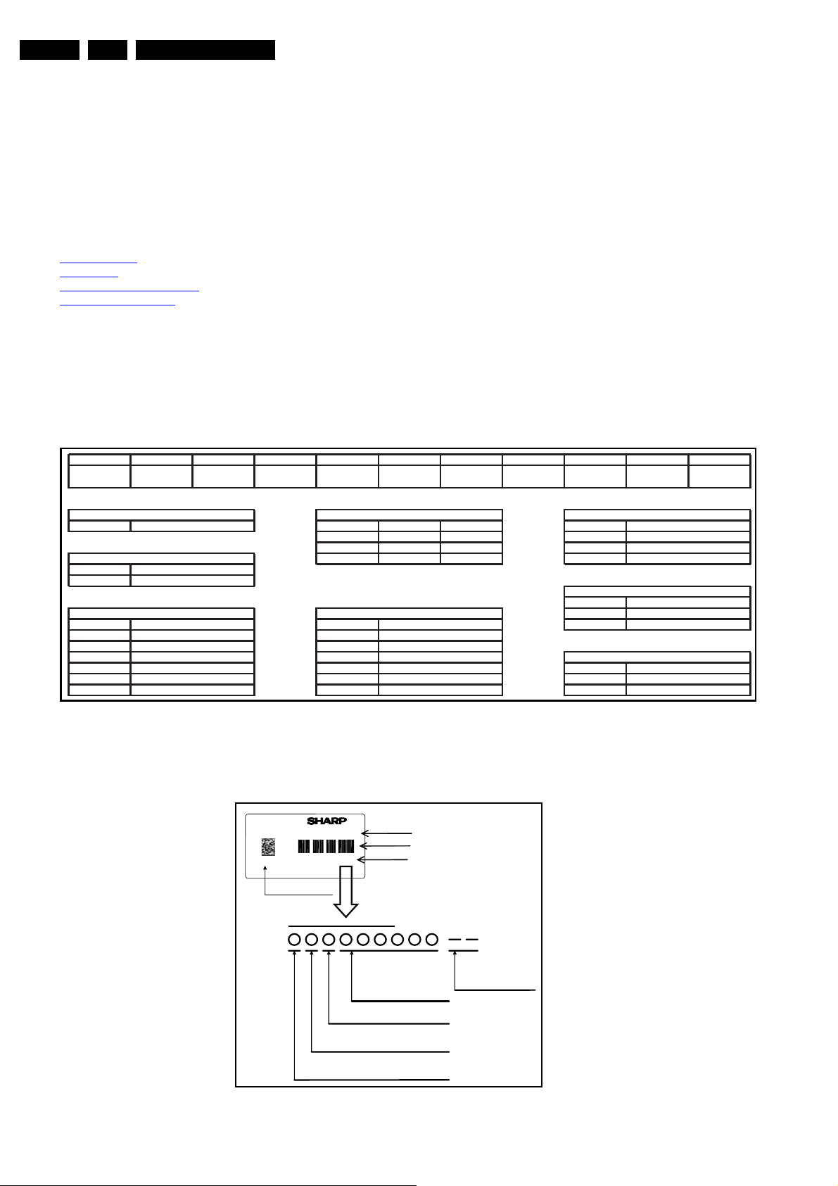
2.2 General
1234567891011
LK5 58Z3LA13
1 - Display Technology
L D Full HD 1920x1080 A
2 - Production Plant
K
…
3, 4, 5 - Display Size
315 1 …
370 3
420 5
470 2
520 4 1st digit
558 6 2nd digit
………
LCD
Kameyama
32 inch
37 inch
42 inch
47 inch
52 inch
56 inch
2.1 Introduction
In this Service Manual you will find all necessary information to
perform the Board Level Repair (= board swap) scenario on
LCD panels. These LCD repair manuals are created per brand,
and they will contain all necessary information for the different
panels used in Philips flat LCD TVs.
6 - Display Resolution
T HD ready 1280x720 C
Z
……
7 - Display Type
Cinemascope
Transmissive (OA)
Transmissive (AV)
Transmissive (Car)
Reflective (OA)
Reflective (AV)
Reflective (Car)
2560x1080 L
8 - Input Signal Type / BL
9 - Display Type
A
Z
10, 11 - Serial Number
Analogue
Composite
LVDS
External User
Internal Sharp
3 = Philips
18480_001_090401.eps
090401
2009-Apr-24
Figure 2-1 Type number explanation
䌌䌋䋵䋵䋸䌚䋳䌌䌁䋱䋳
㪐㪈㩷 㪢 䋰䋰䋰䋰䋱
2D Barcode
How to express the Lot number
Number for production month
(1-9. X= 10, Y=11, Z=12)
Number for A production year
(Number on manufacturing year's right edge)
/QFWNG0Q
$CTEQFG
.QV0Q
Serial number of product
Product Factory
Management number
18480_002_090401.eps
090401
Figure 2-2 Serial number explanation
Page 3
Technical Specifications and Connections
EN 3LCD Sharp 2k9 2.
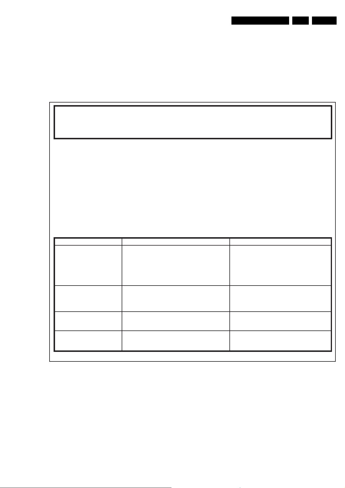
2.3 Technical Specifications
Below find attached the data sheets of the different LCD
panels. Click on the “model number” to open.
• LK520D3LA13
• LK558Z3LA1P (= LK558Z3LA13 with inverters)
2.4 Pixel Specifications
Philips CE
Flat Panel SQA
Reference:
FPSQ090101SI
Starting point for judgment of cosmetic defects: any cosmetic defect is unacceptable
when visible within 10 seconds at a viewing distance of 4 x height of the display
Note 1. At all realistic test patterns and specied viewing angles
Note 2. At ambient room conditions (25 ± 3
Note 3. Customer opinion prevails.
Date:
1-Jan-2009
Cosmetic spec waiver
12NC:
All TV model
o
C, 65 ± 5 % RH) with non -directive lighting (luminance 150 Lux)
Part name:
All TV model
Expire date:
31-Dec-2009
1,2,3
2009 waiver for Sharp LCD panels:
Defect A grade (0/7/7) Remarks
Bright defect (full/half dot defect,
foreign material in panel or
under polarizer)
Dark defect (dot defect or
foreign material on backlight)
Polarizer scratch Max 5 W<0.2 mm, L<5 mm Should not be visible when panel is switched o,
Non-uniformity (mura) Black uniformity: judge at 150 Lux
Min distance between defects: 15 mm.
No full bright dots.
Max 10 weak bright defects:
• Point defects: ≤50% sub-pixel area or not visible
using 2% ND lter.
• Long defect: not visible using 2% ND lter,
L<5mm
Max 7 dark dots (adjacent dark dots count as 2).
Max 14 half/dark dots (1 dark dot count for 2x½ DD)
Max 5 point defect D<1.2 mm
Max 5 long defect W<1mm, L<5 mm
Mid-grey mura: judge in moving picture (for
example Philips “air show” or “Scooby Doo” clip)
Figure 2-3 Cosmetic specification waiver
2% ND lter judgment using black test pattern
under 150 Lux environmental lighting :
HD: max 1 pair of adjacent dark dots, volume
limit is 2% (dGG < 0.2%).
FHD: max 2 pair of adjacent dark dots, volume
limit is 5% (dGG < 0.5%).
at 4xH distance, over the specied viewing angle
range.
Supplier responsible to calibrate with internal
panel inspection method.
18470_003_090403.eps
090403
2009-Apr-24
Page 4
EN 4 LCD Sharp 2k92.
㪣㪢 㪌㪌㪏㪱㪊㪣㪘㪈㪊
㪣㪢㪌㪌㪏㪱㪊㪣㪘㪈㪧
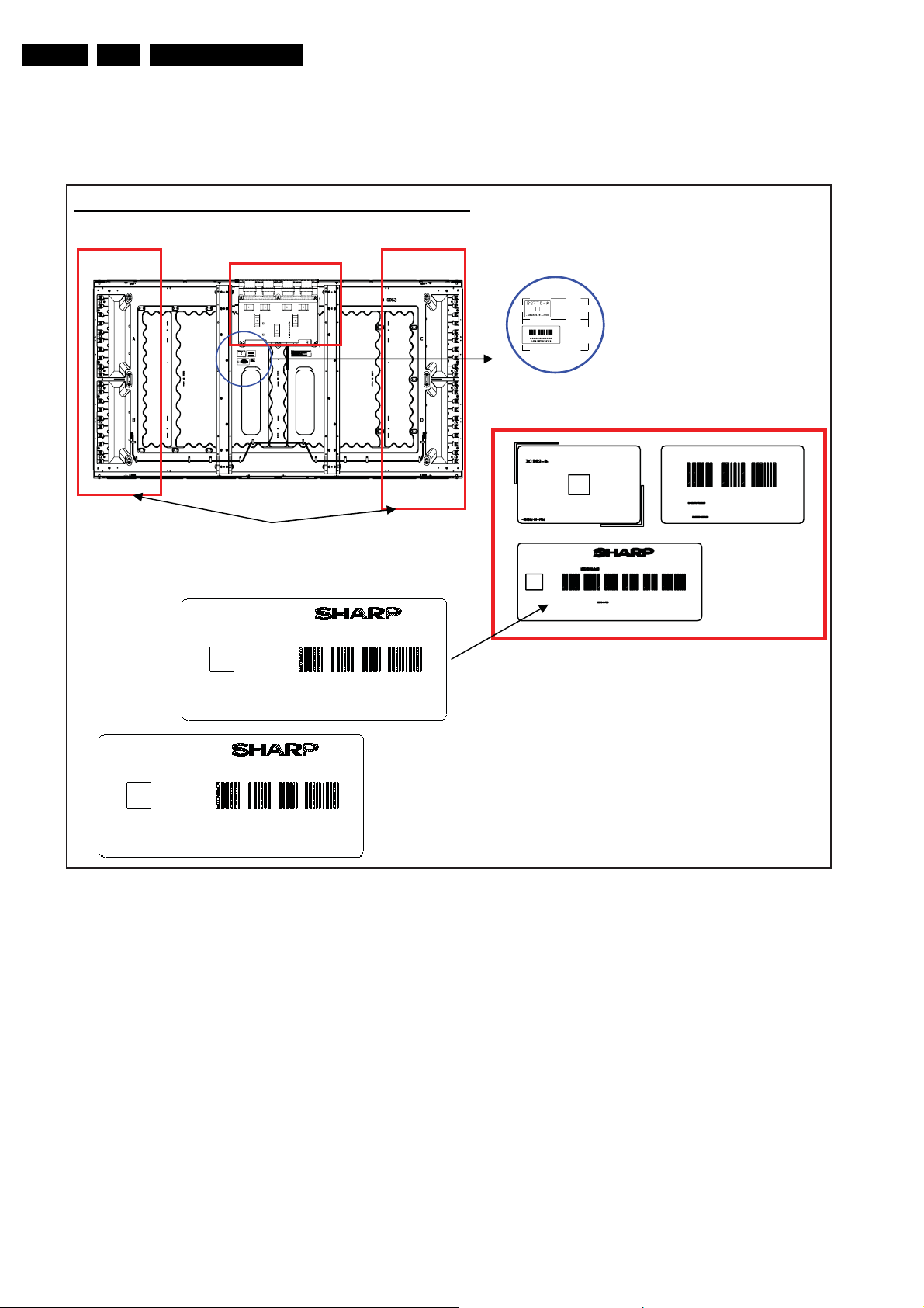
2.5 Board and Label Locations
2.5.1 32-inch models
Label sticking position (LK558Z3LZ1P)
Control-PWB
Technical Specifications and Connections
Inverter-PWB
91 K00001
91 K00001
Figure 2-4 Board and label location
Bar code label
18480_004_090403.eps
090403
2009-Apr-24
Page 5

Precautions, Notes, and Abbreviation List
3. Precautions, Notes, and Abbreviation List
EN 5LCD Sharp 2k9 3.
Index of this chapter:
3.1 General
3.2 Safety Precautions
3.3 Servicing Precautions
3.4 Notes
3.5 Abbreviation List
3.1 General
Notes:
• Only authorised persons should perform servicing of this
module.
• When using/handling this unit, pay special attention to the
LCD Module: it should not be enforced into any other way
then next rules, warnings, and/or cautions.
• "Warning" indicates a hazard that may lead to death or
injury if the warning is ignored and the product is handled
incorrectly.
• "Caution" indicates a hazard that can lead to injury or
damage to property if the caution is ignored and the
product is handled incorrectly.
3.2 Safety Precautions
3.2.1 Warning
• Do not supply a voltage higher than specified to this
product. This may damage the product or can create
hazardous situations.
• Do not use this product in locations where the humidity is
extremely high, where it may be splashed with water, or
where flammable materials surround it.
• Do not install or use the product in a location that does no
satisfy specified environmental conditions. This may
damage the product or can create hazardous situations.
• If a foreign substance (such as water, metal, or liquid) gets
inside the product, immediately turn “OFF” the power.
Continuing to use the product may cause electric shock or
can create hazardous situations.
• If the product emits smoke and abnormal smell, or makes
an abnormal sound, immediately turn “OFF” the power.
Continuing to use the product may cause electric shock or
can create hazardous situations.
• Do not (dis)connect the connector while power to the
product is “ON”. It takes some time for the voltage to drop
to a sufficiently low level after the power has been turned
“OFF”. Confirm that the voltage has dropped to a safe level
before (dis)connecting the connector.
• Do not pull out or insert the power cable from/to an outlet
with wet hands. It may cause electric shock.
• If the power cable is damaged, or if the connector is loose,
do not use the product, otherwise, this can lead to
hazardous situations or may cause electric shock.
• The LCD Backlight Inverter unit uses a high voltage for the
lamps. Keep the cautions concerning electric shock and do
not touch the device circuitry handling the inverter unit. And
because the capacitors of the device circuitry may remain
charged at the moment of Power “OFF”, standing for 1
minute is required in order to discharge the device circuitry.
3.2.2 Caution
• Do not place this product in a location that is subject to
heavy vibration, or an unstable surface such as an inclined
surface. The product may fall off or fall over, causing
injuries.
• Before disconnecting cable from the product, be sure to
turn off the power. Be sure to hold the connector when
disconnecting cables. Pulling a cable with excessive force
may cause the core of the cable to be exposed or break the
cable, and this can lead to fire or electric shock.
• This product contains glass. If shock, vibration, heat or
distortion is applied to the product, the glass may be
broken.
• If glass surface of the display breaks or is scratched, do not
touched the broken pieces or the scratched with bare
hands. You may be injured.
• LCD Module requires to be handled with special care. LCD
Module is not to be touched with metal or hard materials.
Must not be stressed by heat or mechanical impact.
• There are some particular components on the rear panel of
this product. Skin contact with these components may
cause an electric shock. So, handle with care.
• While moving the product, be sure to turn off the power,
disconnect all cables and watch your step. Dropping the
product may cause injuries from electric shock. So, while
moving the product handle with care.
• When cleaning the panel is necessary, wipe it with a soft
and moistened cloth a neural detergent. Caution on
connector area. Do not use chemicals such as thinner or
benzene.
• LCD Module emits heat from the Lamp, Backlight lamp,
and component parts. Therefore, the environmental
temperature must not exceed 50 deg. C. LCD Module
Backlight Inverter system is driven by high voltage, so it
must avoid conductive materials.
• If repairing components with a lead line, high voltage or
high temperature components must be put out from a lead
line and fix.
• Do not place an object on the surface of the display. The
glass may break or be scratched.
• This product may be damaged if it is subject to excessive
stresses (such as excessive voltage, current, or
temperature). The absolute maximum ratings specify the
limits of these stresses.
• Do not cover or wrap with any covering materials while
power is applied to the product.
• This product is made from various materials such as glass,
metal, and plastic. When discarding it, be sure to contact a
purchase place.
• If a discrepancy occurs due to any arbitrary modification or
disassembly, supplier is not responsible for function,
quality or other items.
• Within the warranty period, general faults may be charged
for depending on responsibility for the faults. You handle
with care
3.3 Servicing Precautions
A colour TFT LCD Module can easily be damaged by both
electrical and mechanical stresses. Users therefore, are
requested to implement the following rules.
3.3.1 System Assembler
• Follow the power sequence: An abnormal power
sequence may cause critical malfunction or electrical
damage.
• Prevent physical stress.
• Prevent overheat:
– High temperatures on the surface of the screen may
cause poor quality. Please use the LCD Module on the
specified temperatures.
– Low temperatures (under 10 deg. C) makes the LCD
Module respond slowly, make the Backlight worse
operated, and will shorten very much the lifetime
accordingly.
2009-Apr-24
Page 6

EN 6 LCD Sharp 2k93.
Precautions, Notes, and Abbreviation List
• Keep LCD Module dust-free: The LCD Module is
sensitive against dust; it can cause visual or functional
problems.
• Do not touch TCP area: Do not touch TCP area at any
case. It can cause Driver IC cracks, film cracks, etc. The
TCP is the weakest point of the LCD Module.
• Do not pull Backlight wire: Please do not pull the
Backlight wire, as it can cause the wire to become
disconnected or damaged.
• Check the connections of the Inverter & Backlight
connectors: Incomplete connection can cause burnt in
Backlight connectors or damage the inverter.
• Handle with care:
– Please do not drop, bend, or hit the LCD Module.
– Physical stress can cause defects as broken panels.
• Keep mounting screw length and motor driver’s
torque: Strong motor driver’s torque can make a
mechanical defect on LCD Module. Please keep within the
specifications.
• Do not operate for a long time under the same pattern:
Operating the LCD Module for a long time with the same
video pattern can cause image persistence and can
eventually damage it.
• Defective panels must also be handled with care:
– To prevent making other defects, please handle the
defective LCD Module as a good one.
– Defective LCD Modules must be repaired.
• Do not stack LCD Modules: The LCD Module consists of
fragile components such as TCPs or Glasses. Stacking the
LCD Modules can cause undesired defects.
• Do not provide strong pressure at connecting: Strong
pressure can transfer the force to the TCP, which is the
weakest part of the LCD Module. It eventually can make
the TCP crack or lead to other unexpected defects.
• Let the Backlight Wire at the backside of the LCD
Module: If let the Backlight wire in front of the LCD Module,
the Backlight connector can hurt the surface of the
polariser.
• Never (dis)connect at power “ON”: The LCD Module
consists of CMOS components, which are known as weak
components against EOS. It can damage the product.
• Electrostatic discharge can make damage:
– Semi-assembled product should be handled with wrist
strap.
– Earth human body when handle the LCD Module.
– Please do not touch the interface connector pin.
3.3.2 System Assembler/End User
• Keep the surface clean :
– Please wear rubber gloves when you touch the surface
of the LCD Module screen.
– Please use soft and anti-static material with n-Hexane
as cleaner.
• Be careful not to scratch the polariser :
– Surface of polariser is soft, so it’s easily scratched.
– Please do not touch, press or rub on polariser surface
with materials over HB hardness.
• Be careful with swift temperature and humidity
changes: Swift temperature and or humidity change can
make dew condensation or ice, which can cause nonconformance such as malfunctioning.
• Keep out of water:
– Water on in the LCD Module can cause electrical short
or corrosion.
– Please wipe out or dry water carefully.
• Keep the LCD Module free from corrosive gasses:
Corrosive gas can chemically damage the polariser and
the circuitry parts and eventually will cause defects.
• Keep the suitable temperature and humidity: High
temperatures and high humidity will shorten the lifetime
3.4 Notes
3.4.1 Spare Parts
For the latest spare part overview, please consult your Philips
Spare Part web portal.
3.5 Abbreviation List
AUO Acer Unipack Optronics (supplier)
CCFL Cold Cathode Fluorescent Lamp
CMO Chi Mei Optoelectronics (supplier)
COF Chip On Flex / Foil / Film
CPT Chunghwa Picture Tubes (supplier)
DC Direct Current
FET Field Effect Transistor
FFC Flat Foil Cable
FPC Flexible Printed Circuit
IC Integrated Circuit
IPB Integrated Power Board (PSU incl.
inverter)
LCD Liquid Crystal Display
LCM Liquid Crystal Module
LED Light Emitting Diode
LGD LG Displays (supplier)
LPL LG Philips LCD (supplier)
PCB Printed Circuit Board (same as PWB)
PSU Power Supply Unit
PWB Printed Wiring Board (same as PCB)
RGB Red, Green, Blue colour space
TCP Tape Carrier Package
2009-Apr-24
Page 7
4. Mechanical Instructions
Mechanical Instructions
EN 7LCD Sharp 2k9 4.
Index of this chapter:
4.1 General
4.2 Model LK520D3LA13
4.3 Model LK558Z3LA1P
4.4 Model LK558Z3LA13
4.1 General
4.1.1 Warnings
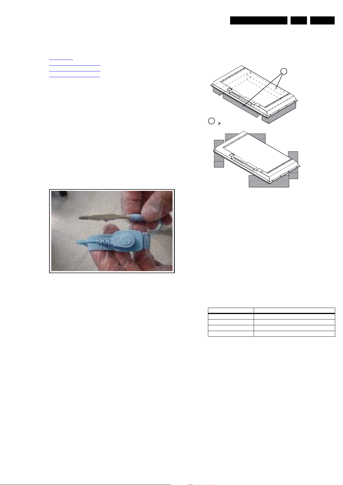
• Figures can deviate due to the different module executions.
• During repair, place the set face down on a soft surface
(e.g. on foam bars as mentioned in next paragraph), in
order to prevent damaging the display.
Note: With some chassis, it is possible to measure and
replace the boards while the TV is still on its stand.
• All ICs and many other semiconductors are susceptible to
electrostatic discharges (ESD w). Careless handling
during repair can reduce life drastically. Make sure that,
during repair, you are connected with the same potential as
the mass of the set by a wristband with resistance. Keep
components and tools also at this same potential.
Figure 4-1 ESD wristband
• Be careful during measurements in the high voltage
section. Never pull plugs out under operation conditions,
just to prevent danger caused by electrical sparks.
• Never replace modules or other components while the unit
is switched “on”.
• Connectors “to” and “from” the Inverter Boards must be
thoroughly connected to avoid any electrical sparks during
operation.
H_16920_001.eps
060407
4.1.2 Foam Bars
1
Required for sets
1
42"
E_06532_018.eps
171106
Figure 4-2 Foam bars
The foam bars (order code 3122 785 90580 for two pieces) can
be used for all types and sizes of flat displays. See figure
“Foam bars” for details. Displays with a size of 42” and larger,
require four foam bars [1]. Ensure that the foam bars are
always supporting the cabinet and never only the display.
Caution: Failure to follow these guidelines can seriously
damage the display!
By laying the TV face down on the (ESD protective) foam bars,
a stable situation is created to perform measurements and
alignments. By placing a mirror under the display, you can
monitor the screen.
4.1.3 Torque Values
Table 4-1 Recommended Torque Values
Screw Type (cross head) Recommended Torque Value
M2 2.0 kg*F ± 0.1 kg*F
M2.5 3.0 kg*F ± 0.5 kg*F
M2.6 3.0 kg*F ± 0.5 kg*F
M3 6.0 kg*F ± 0.5 kg*F
2009-Apr-24
Page 8
EN 8 LCD Sharp 2k94.
4.2 Model LK520D3LA13
Mechanical Instructions
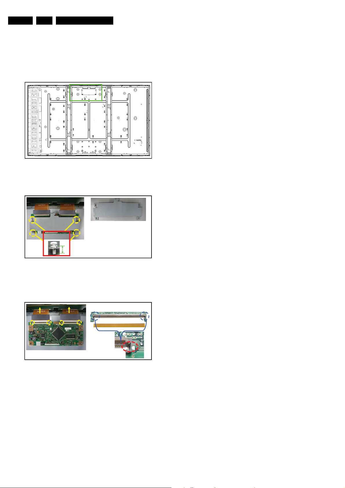
4.2.1 Control Board
Disassembly
1. Place the panel face down on the foam bars, and locate the
Control board.
Figure 4-3 Control board location
2. Remove the screws of the metal cover.
C-PWB Cover
18481_201_090423.eps
Reassembly
To reassemble, perform all processes in reverse order.
Important: Be sure to insert the FFCs correctly.
090423
screw
× 4
6 mm
18481_202_090423.eps
Figure 4-4 Cover screws removal
3. Carefully disconnect the flat cable/FFCs from their
connectors.
The FPC salient is put in the concave connector
part, and the connector is locked properly
Ferrite core Ferrite core
18481_203_090423.eps
Figure 4-5 Flat cable removal
4. You now can remove the Control Board.
090423
090423
2009-Apr-24
Page 9
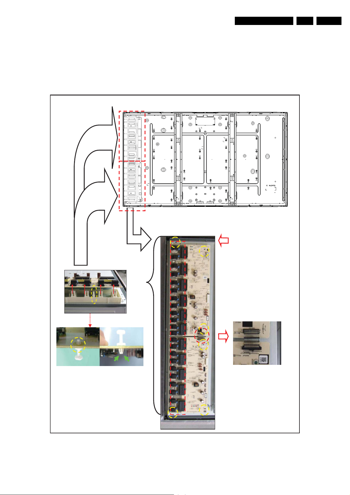
4.2.2 Inverter Board
(
Disassembly
1. Place the panel face down on the foam bars, and locate the
Inverter boards.
2. Remove the cover screws, and remove the cover.
3. Unplug and remove the Inverter boards as shown in next
figure
Mechanical Instructions
EN 9LCD Sharp 2k9 4.
12 Lamp connectors
10 Lamp connectors
3: Detach lamp
connector on
12&10 places
Inverter
Rear view
㧝: Detach screw
at 6 places each
RDENC2559TPZF
slave - 1 side)
Figure 4-6 Unplug and remove Inverter board
Reassembly
To reassemble, perform all processes in reverse order.
2: Detach
RDENC2560TPZF
(master - 1 side)
connections
18481_204_090424.eps
090424
2009-Apr-24
Page 10
EN 10 LCD Sharp 2k94.
s
3
s
3
4.3 Model LK558Z3LA1P
Mechanical Instructions
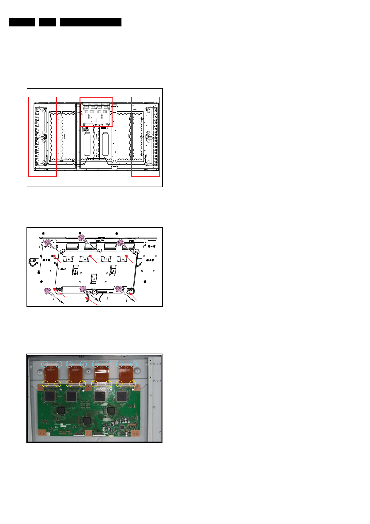
4.3.1 Control Board
Disassembly
1. Place the panel face down on the foam bars, and locate the
Control board.
Control-PWB
Inverter-PWB
Figure 4-7 Control board location
2. Remove the screws of the metal cover.
Inverter-PWB
18480_202_090403.ep
09040
Reassembly
To reassemble, perform all processes in reverse order.
Important: Be sure to insert the FFCs correctly.
18480_201_090403.ep
Figure 4-8 Cover screws removal
3. Carefully disconnect the flat cable/FFCs from their
connectors.
18480_203_090403.eps
Figure 4-9 Flat cable removal
4. You now can remove the Control Board.
09040
090403
2009-Apr-24
Page 11
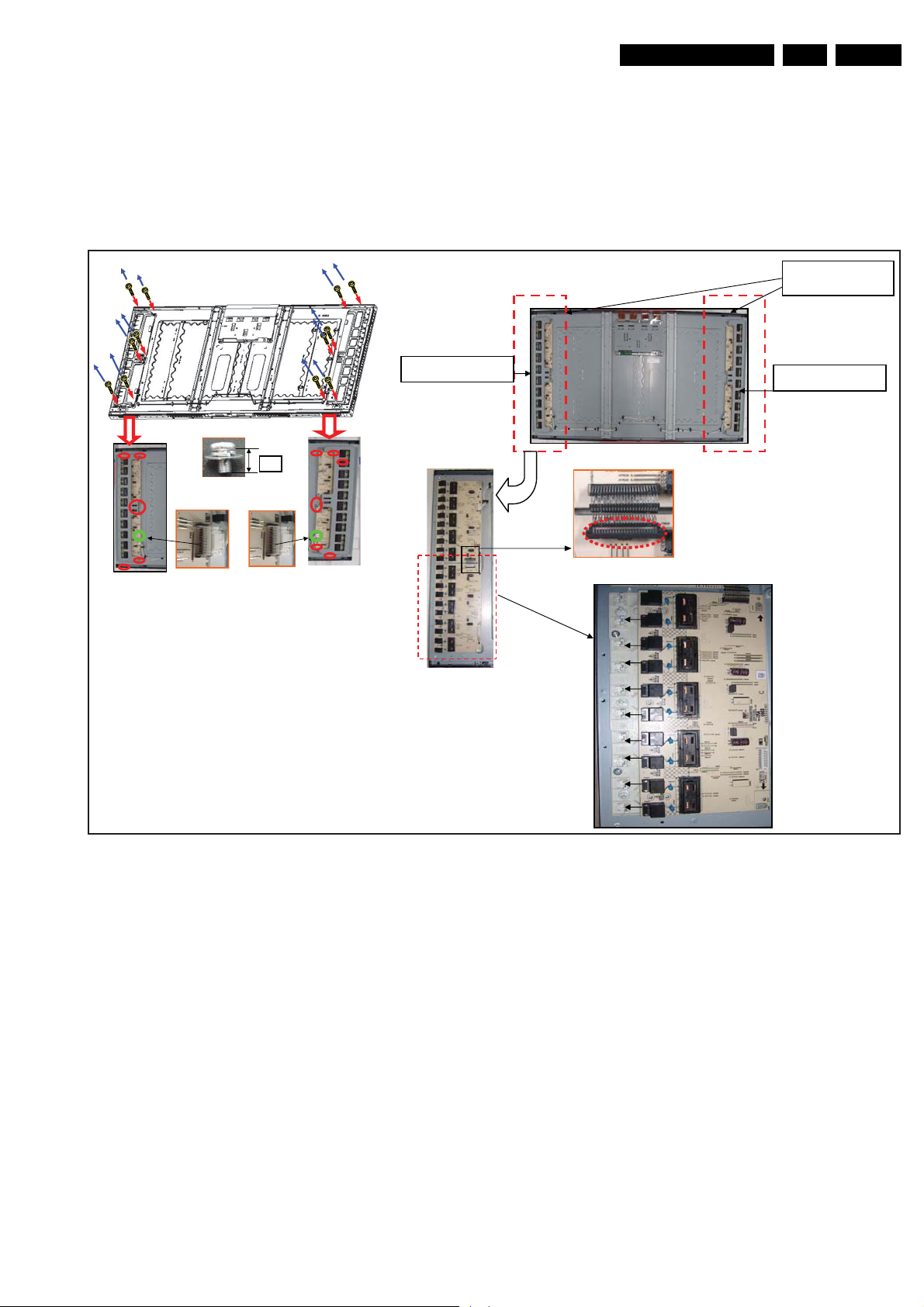
4.3.2 Inverter Board
Disassembly
1. Place the panel face down on the foam bars, and locate the
Inverter board (refer to figure “4.3 Control board location”).
2. Remove the cover screws, and remove the cover.
3. Unplug and remove the Inverter board as shown in next
figure
Mechanical Instructions
EN 11LCD Sharp 2k9 4.
LK558Z3LA13:
Without Inverters
8mm
Inverter-PWB Cover
Inverter-PWB Cover
Figure 4-10 Unplug and remove Inverter board
Reassembly
To reassemble, perform all processes in reverse order.
4.4 Model LK558Z3LA13
The (dis)assembly process is identical to the LK558Z3LA1P.
The only difference is that the LK558Z3LA13 comes without
Inverters.
18480_204_090403.eps
090403
2009-Apr-24
Page 12
EN 12 LCD Sharp 2k95.
y
y
y
Service Modes, Error Codes, and Fault Finding
5. Service Modes, Error Codes, and Fault Finding
Index of this chapter:
5.1 Service Modes
5.2 Error Codes
5.3 Fault Finding
5.3.1 General
5.3.2 LK520D3LA13
5.3.3 LK558Z3LA1P and LK558Z3LA13
5.1 Service Modes
Not applicable.
5.2 Error Codes
Not applicable.
5.3 Fault Finding
5.3.1 General
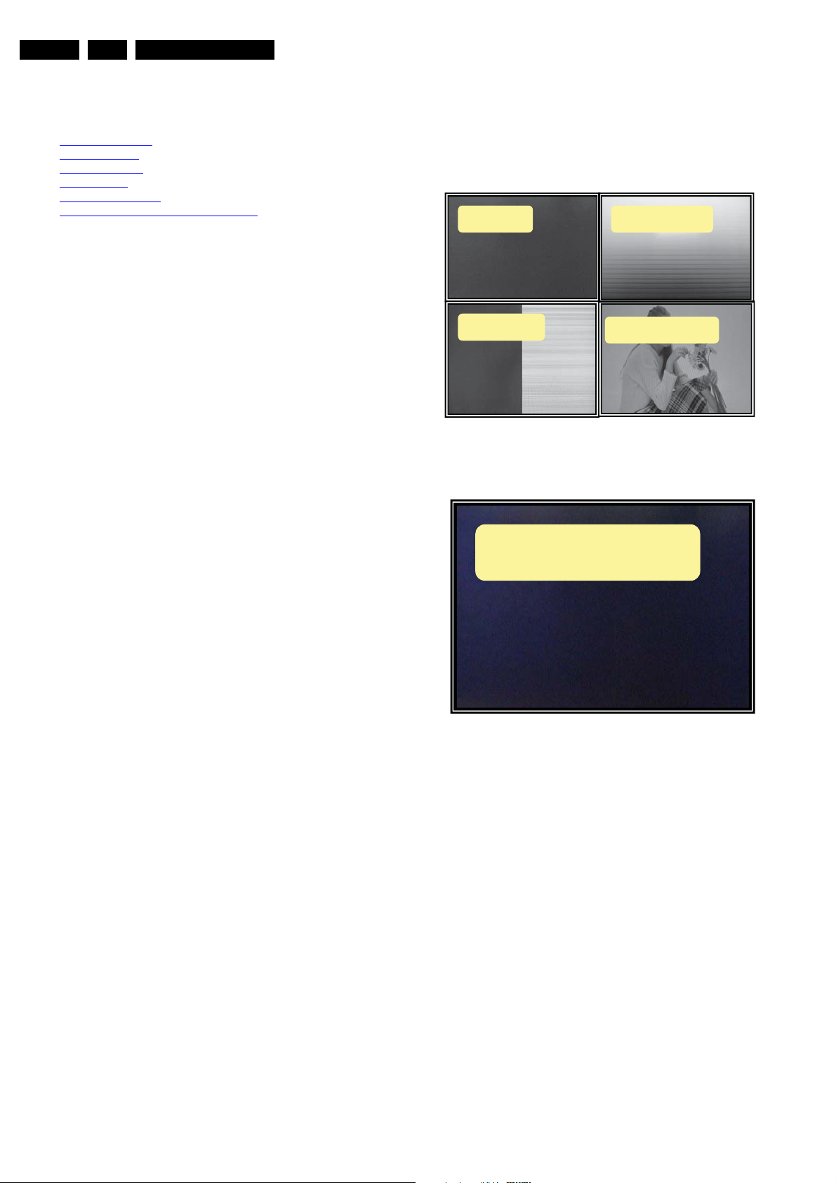
No displa
Half displa
Figure 5-1 Symptoms for checking the Control Board
Horizont al stripe
Wavystripedispla
I_17811_026.eps
260908
No back light / Flickering
Low brightness / Shut down
I_17811_027.eps
Figure 5-2 Symptoms for checking the Inverter Board
090403
2009-Apr-24
Page 13
5.3.2 LK520D3LA13
Service Modes, Error Codes, and Fault Finding
EN 13LCD Sharp 2k9 5.
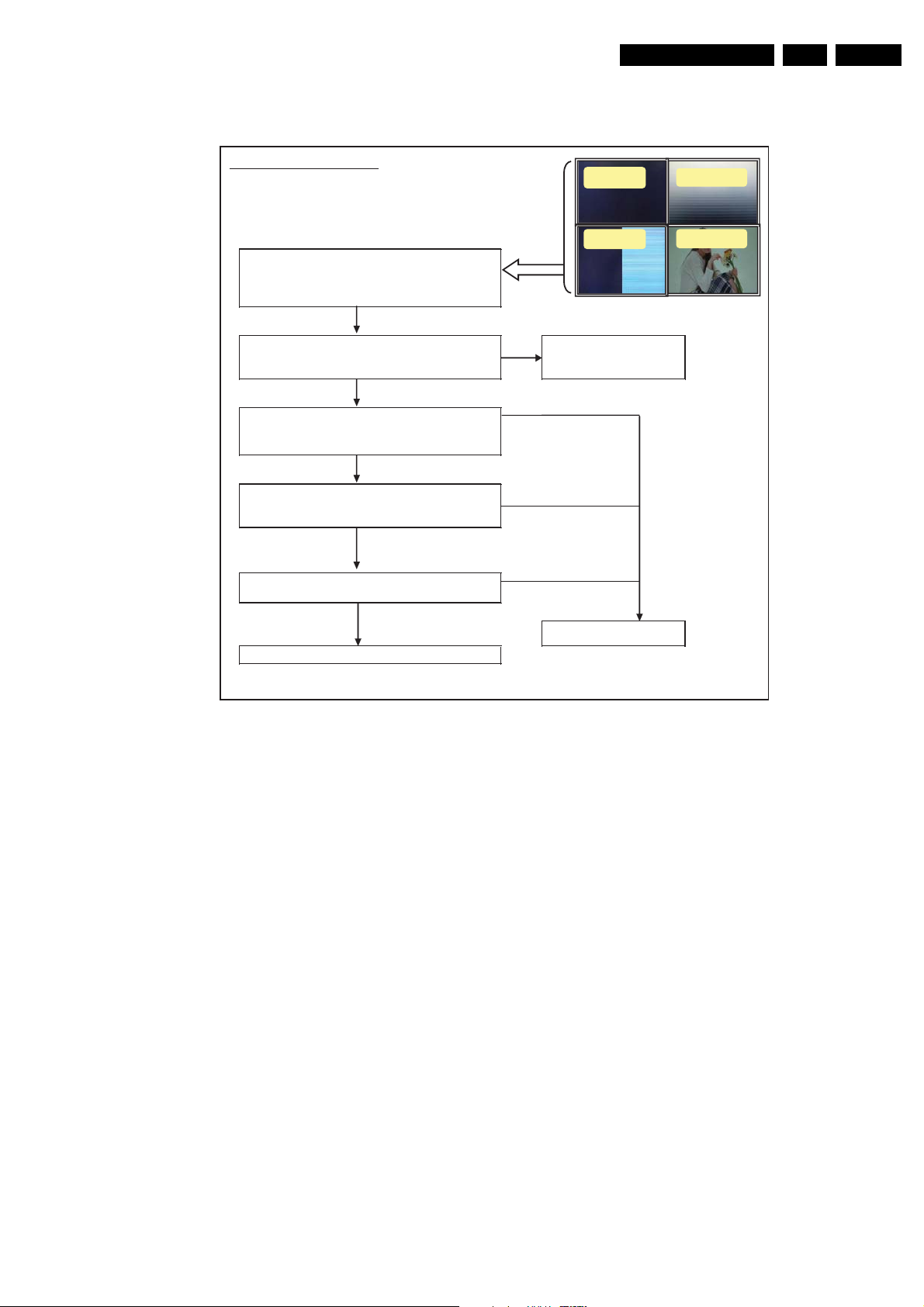
Trouble Shooting Table
For Control –PWB (LK520D3LA13)
STEP 1
Phenomenon
1. No Display
2. Abnormal Display
ޓޓ(Half Screen Image / Abnormal Display etc.)
STEP 2
Check cable connection to C-PWB Insert the connector correctly
ޓ1. Cable to LVDS or
ޓ2. FPC between Source-PWB and Contorl-PWB Change the cable and FPC
STEP 3
Check Voltage
Check if CN1) 47 to 51pins of LVDS connector 㧔51pin) are
12V or not
STEP 4
Check if LVDS signal is input to following pins or not.
ޓޓޓCN1ޓ12-17,19-20,23-25,28-34,36-37,39-41pin
STEP 5
Check if SELLVDS signal (CN1:7pin) is "H" or "Open" not.
OK
OK
OK
NG
NG
NG
NG
No display
Half display Wavy stripe
Horizontal stripe
STEP 6 Check the main board of TV set
Exchange the C-PWB
OK
Figure 5-3 Trouble shooting table for Control Board
18481_205_090424.eps
090424
2009-Apr-24
Page 14
r
EN 14 LCD Sharp 2k95.
Service Modes, Error Codes, and Fault Finding
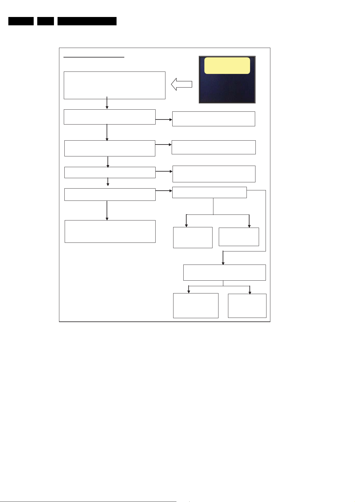
Trouble Shooting Table
For Inverter –PWB(LK520D3LA13)
The possible failure phenomenon would be:-
1. No Back Light
2. Flickering
3. Low Brightnes
4. Shut down after 3 seconds from switching ON
Check cab le conn ection to Inverter
㧝㧚Cable to 14pin connector
Check Voltage
Check if 1 to 5 pins of 14pin connector are 24V or not.
Check if 12pin of 14pin connector is 3.3V or not
Check if 13pin of 14pin connector is more than 3.3V o
not.
Exchange the Inverter and go to next stage
* If phenomenom #2, 3, or 4 still exist even
after exchange inverter.
OK
OK
OK
OK
3.3V or more
Insert the co nnector corre ctly
NG
or
Change the cable
NO
Check the power supply
(the phenomenon should be #1 of "STEP1")
NO
Check the main board of TV set
(the phenomenon should be #1 of "STEP1")
NO
Check if 14pin of 14pin connector is 3.3V or
not
From 0V to3.3V
0V:㧦13pin
In ca s e of
Phenomenon
#1, 2, or 4, Inverter
should be changed.
Check the voltage of 13pin of 14pin connector
Brightness should be changed by voltage from 0
to 3.3V
In case of Phenomenon
#1, 2, or 4, Inverter should
be changed and go to next
stage
No Backlight / Flickering
Low brightness /Shut down
0V
From 0.5V to
3.3V=13pin
In ca s e of
Phenomenon #3, it is
normal.
In ca s e of
Phenomenon
#3, it is normal.
(depend on voltage
level)
18481_206_090424.eps
3.3V
090424
2009-Apr-24
Figure 5-4 Trouble shooting table for Inverter Board
Page 15
Service Modes, Error Codes, and Fault Finding
㫇
5.3.3 LK558Z3LA1P and LK558Z3LA13
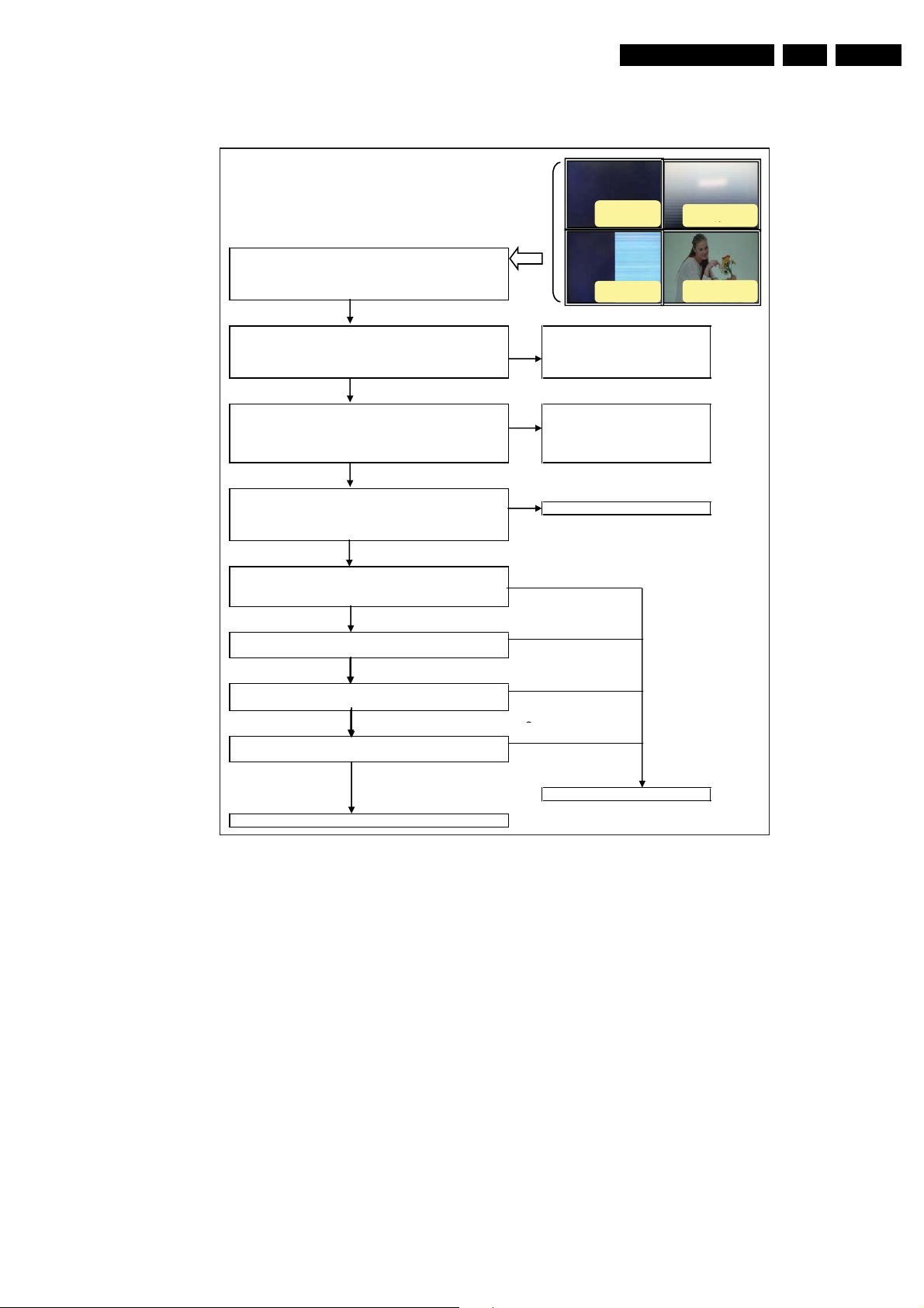
Trouble Shooting Table
ForControl-PWB (LK558Z3LA1P and 13)
㪪㪫㪜㪧㩷㪈
㩷㪧㪿㪼㫅㫆㫄㪼㫅㫆㫅
㩷㩷㪈㪅㩷㪥㫆㩷㪛㫀㫊㫇㫃㪸㫐
䇭㪉㪅㩷㪘㪹㫅㫆㫉㫄㪸㫃㩷㪛㫀㫊㫇㫃㪸㫐
㩷㩷䇭䇭㩿㪟㪸㫃㪽㩷㪪㪺㫉㪼㪼㫅㩷㪠㫄㪸㪾㪼㩷㪆㩷㪘㪹㫅㫆㫉㫄㪸㫃㩷㪛㫀㫊㫇㫃㪸㫐㩷㪼㫋㪺㪅㪀
㪪㪫㪜㪧㩷㪉
㩷㩷䋱㪅㪚㪸㪹㫃㪼㩷㫋㫆㩷㫇㫆㫎㪼㫉䇭㫊㫌㫇㫇㫃㫐
䇭㪊㪅㩷㪝㪧㪚㩷㪹㪼㫋㫎㪼㪼㫅㩷㪪㫆㫌㫉㪺㪼㪄㪧㪮㪙㩷㪸㫅㪻㩷㪚㫆㫅㫋㫆㫉㫃㪄㪧㪮㪙 㩷㪚㪿㪸㫅㪾㪼㩷㫋㪿㪼㩷㪺㪸㪹㫃㪼㩷㪸㫅㪻㩷㪝㪧㪚
㪪㪫㪜㪧㩷㪊
㩷㪚㪿㪼㪺㫂㩷㪭㫆㫃㫋㪸㪾㪼
㪚㪿㪼㪺㫂㩷㫀㪽㩷䋨㪚㪥㪈㪀㪋㪎㩷㫋㫆㩷㪌㪈㫇㫀㫅㫊㩷㫆㪽㩷㪣㪭㪛㪪㩷㪺㫆㫅㫅㪼㪺㫋㫆㫉㩷㩽
㩿㪚㪥㪊㪀㪈㫋㫆㪉㫇㫀㫅㫊㩷㫆㪽㩷㫇㫆㫎㪼㫉㩷㫊㫌㫇㫇㫃㫐㩷㪺㫆㫅㫅㪼㪺㫋㫆㫉㩷㪸㫉㪼㩷㪈㪉㪭㩷㫆㫉㩷㫅㫆㫋
㪦㪢
No display
Half display
㪥㪞
㫉㫆
㩷㩷㪪㪛㪭㪣㩷㫆㫋㩷㪼㫃㪹㪸㪚㩷㪅㪉䇭
㪥㪞
㩷㪚㪿㪼㪺㫂㩷㫋㪿㪼㩷㫄㪸㫀㫅㩷㪹㫆㪸㫉㪻㩷㫆㪽㩷㪧㫆㫎㪼㫉
㩽㪫㪭㩷㫊㪼㫋
EN 15LCD Sharp 2k9 5.
Horizontal
Wavy stripe
㫐㫃㫋㪺㪼㫉㫉㫆㪺㩷㫉㫆㫋㪺㪼㫅㫅㫆㪺㩷㪼㪿㫋㩷㫋㫉㪼㫊㫅㪠㩷㪙㪮㪧㪄㪚㩷㫆㫋㩷㫅㫆㫀㫋㪺㪼㫅㫅㫆㪺㩷㪼㫃㪹㪸㪺㩷㫂㪺㪼㪿㪚㩷
㪪㪫㪜㪧㩷㪋
㩷㪚㪿㪼㪺㫂㩷㫀㪽㩷㪣㪭㪛㪪㩷㫊㫀㪾㫅㪸㫃㩷㫀㫊㩷㫀㫅㫇㫌㫋㩷㫋㫆㩷㪽㫆㫃㫃㫆㫎㫀㫅㪾㩷㫇㫀㫅㫊㩷㫆㫉㩷㫅㫆㫋㪅
䇭䇭䇭㪚㪥㪈䇭㪈㪉㪄㪈㪎㪃㩷㪈㪐㪄㪉㪇㪃㩷㪉㪉㪄㪉㪌㪃㩷㪉㪏㪄㪊㪊㪃㩷㪊㪌㪄㪊㪍㪃㩷㪊㪏㪄㪋㪈㫇㫀㫅 㩷㪚㪿㪼㪺㫂㩷㫋㪿㪼㩷㫄㪸㫀㫅㩷㪹㫆㪸㫉㪻㩷㫆㪽㩷㪫㪭㩷㫊㪼㫋
㪦㪢
㪥㪞
䇭䇭䇭㪚㪥㪉䇭㪈㪇㪄㪈㪌㪃㩷㪈㪎㪄㪈㪏㪃㩷㪉㪇㪄㪉㪊㪃㩷㪉㪍㪄㪊㪈㪃㩷㪊㪊㪄㪊㪋㪃㩷㪊㪍㪄㪊㪐㫇㫀㫅
㪪㪫㪜㪧㩷㪌
㩷㩷㪚㪿㪼㪺㫂㩷㫀㪽㩷㪪㪚㪣㪃㪪㪛㪘㩷㫊㫀㪾㫅㪸㫃㩷㩿㪚㪥㪈㪀㩷㪉㩷㪸㫅㪻㩷㪊㫇㫀㫅䇭㫆㫉㩷㫅㫆㫋㪅
㪪㪫㪜㪧㩷㪍
㩷㩷㪚㪿㪼㪺㫂㩷㫀㪽㩷㪤㪦㪛㪜㩷㫊㫀㪾㫅㪸㫃㩿㪚㪥㪈㪀㩷㪐㩷㫋㫆㪈㪇㩷㫇㫀㫅㩷㫀㫊㩹㪣㩹 㫆㫉
㩹㫆
㪼㫅㵱䇭㫅㫆㫋㪅
㪪㪫㪜㪧㩷㪎
㩷㪚㪿㪼㪺㫂㩷㫀㪽㩷㪪㪜㪣㪣㪭㪛㪪㩷㫊㫀㪾㫅㪸㫃㩿㪚㪥㪈㪑㪎㫇㫀㫅㪀㩷㫀㫊㩷㩹㪣㩹㩷㫆㫉㩷㩹㪦㫇㪼㫅㩹
㪦㪢
㪥㪞
㪥㪞
㪥㪞
㫅㫆㫋㪅
㪪㪫㪜㪧㩷㪏
㪥㪞
㩷㪚㪿㪼㪺㫂㩷㫀㪽㩷㪦㪆㪪㩷㫊㫀㪾㫅㪸㫃㩿㪚㪥㪈㪑㪍㫇㫀㫅㪀㩷㫀㫊㩷㩹㪟㩹㩷㫆㫉㩷㩷㩹㪦㫇㪼㫅㩹㫅㫆㫋㪅
㪦㪢
㩷㪚㪿㪼㪺㫂㩷㫋㪿㪼㩷㫄㪸㫀㫅㩷㪹㫆㪸㫉㪻㩷㫆㪽㩷㪫㪭㩷㫊㪼㫋
㩷㪜㫏㪺㪿㪸㫅㪾㪼㩷㫋㪿㪼㩷㪚㪄㪧㪮㪙
Figure 5-5 Trouble shooting table for Control Board
18480_205_090403.eps
090403
2009-Apr-24
Page 16
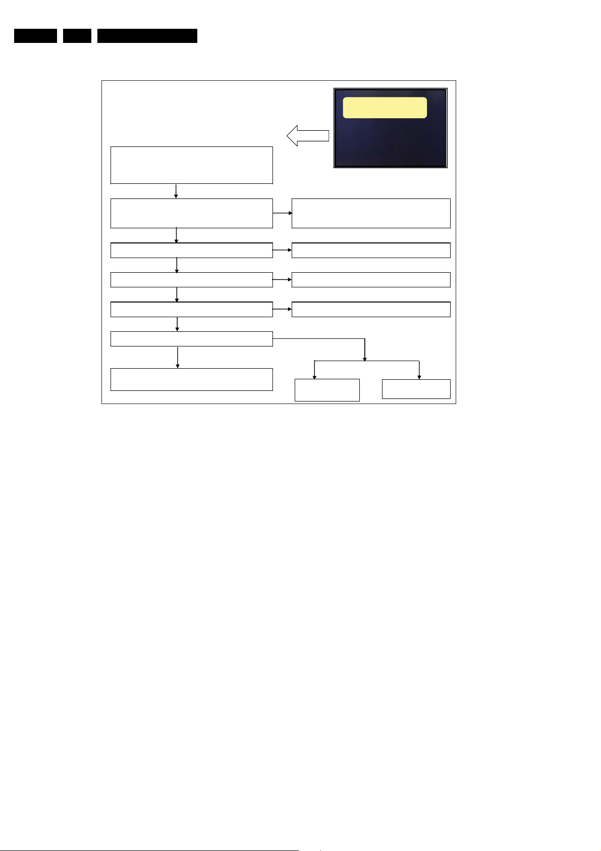
g
EN 16 LCD Sharp 2k96.
Alignments
Trouble Shooting Table
For Inverter-PWB (LK558Z3LZ1P)
STEP 1
The possible failure phenomenon would be:-
1. No Back Light
2. Flickering
3. Low Brightness
4. Shut down after 3 seconds from switching ON
STEP2
C .1
3. Junction Cable between Inverters (in case of 2 sides inverters)
STEP3
Check if 1 to 5 pins of 12 pin connector are 24V or not.
STEP4
STEP5
Check if 䋱䋴pin of 䋱䋴pin connector is 䇭䋰V or not
STEP6
Check if 13pin of 14pin connector is more than 3.3V or not.
Exchange the Inverter and go to next stage
* If phenomenon #2, 3, or 4 still exist even
after exchange of inverter.
㪦㪢
㪦㪢
㪦㪢
㪦㪢
㪊㪅㪊㪭㩷㫆㫉㩷㫄㫆㫉㪼
Figure 5-6 Trouble shooting table for Inverter Board
㪥㪞
ro rotcennoc nip41 ot elba
NO
(the phenomenon should be #1 of "STEP1")
NO
NO
㩷㩷㩷䇭Check the inverter cable or TV set board.
ob niam eht kcehCton ro V3.3 si rotcennoc nip41 fo nip21 fi kcehC
(the phenomenon should be #1 of "STEP1")
NO
㪝㫉㫆㫄㩷㪇㪭㩷㫋㫆㪊㪅㪊㪭
㪇㪭㪔㪈㪊㫇㫀㫅
In case of Phenomenon
#1, 2, or 4, Inverter
should be changed.
No back light / Flickering
Low bri
htness / Shut down
yltcerroc rotcennoc eht tresnI retrevnI ot noitcennoc elbac kcehC
elbac eht egnahC rotcennoc nip21 ot elbaC .2
ylppus rewop eht kcehC egatloV kcehC
tes VT fo dra
㪝㫉㫆㫄㩷㪇㪅㪌㪭㩷㫋㫆㩷㪊㪅㪊㪭㪔㪈㪊㫇㫀㫅
In case of Phenomenon
#3, it is normal.
18480_206_090403.eps
090424
6. Alignments
Not applicable.
7. Circuit Descriptions
Not applicable
8. IC Data Sheets
Not applicable
9. Block Diagrams
Not applicable.
10. Circuit Diagrams and PWB Layouts
Not applicable
2009-Apr-24
 Loading...