

Page 1
1-1 LC5231/5241
1. Safety guidelines
IMPORTANT SAFETY NOTICE
Portable LCD projector
S
ta
n
d
b
y
/O
n
In
p
u
Sta
t
tus
A
u
to
im
a
g
e
Proper service and repair is important to the safe, reliable operation of all Philips Consumer Electronics Company** Equipment. The
service procedures recommended by Philips and described in this service manual are effective methods of performing service
operations. Some of these service operations require the use of tools specially designed for the purpose. The special tools should be
used when and as recommended.
It is important to note that this manual contains various CAUTIONS and NOTICES which should be carefully read in order to minimize the
risk of personal injury to service personnel. The possibility exists that improper service methods may damage the equipment. It also is
important to understand that these CAUTIONS and NOTICES ARE NOT EXHAUSTIVE. Philips could not possibly know, evaluate and
advise the service trade of all conceivable ways in which service might be done or of the possible hazardous consequences of each way.
Consequently, Philips has not undertaken any such broad evaluation. Accordingly, a servicer who uses a service procedure or tool which
is not recommended by Philips must first satisfy himself thoroughly that neither his safety nor the safe operation of the equipment will be
jeopardized by the service method selected.
** Hereafter throughout this manual, Philips Consumer Electronics Company will be referred to as Philips.
WARNING
Critical components having special safety characteristics are identified with an by the Ref. No. in the parts list
and enclosed within a broken line* (where several critical components are grouped in one area) along with the
safety symbol on the schematics or exploded views.
Use of substitute replacement parts which do not have the same specified safety characteristics may create shock,
fire, or other hazards.
Under no circumstances should the original design be modified or altered without written permission from Philips.
Philips assumes no liability, express or implied, arising out of any unauthorized modification of design. Servicer
assumes all liability.
LC5231/00
LC5241/00
UGO S-lite/X-lite
Impact Series
* Broken Line
Contents Page
1. Safety guidelines 1-1
2. Specifications 2-1
3. Warnings & Notes 3-1
4. Mechanical instructions 4-1
5. Block diagrams, Wiring diagram 5-1
6. Directions for use 7-1
7. Alignments & Protections 8-1
8. Parts lists 9-1
PCS 107 321
Published by Consumer Electronics Printed in The Netherlands©Copyright reserved Subject to modification
PCS 107 320
3122 435 40420
Page 2
2. Specifications
LC5231/5241 LC5231/5241
2-1 2-2
2.1 Product specifications
UGO UGO
X-lite Impact S-lite Impact
1000 ANSI lumens 1000 ANSI lumens
XGA resolution SVGA resolution
Compact design - < 2 dm
Ultra lightweight just 1.3 kg
Easy plug&play
Digital picture enhancement
Dimensions; 230 x 48 x 177 mm (WxHxD) < 2 dm
•
Net weight 1.5 kg; ca 3.2 lbs
•
Advanced compatibility for both data and video input; compatible
•
with main notebook computers
High contrast ratio; 650:1 (Full on/off)
•
Digital picture enhance technologies;
•
Digital Zoom (x10), Digital Freeze, Digital
•
Keystone correction
Intuitive Graphic User Interface (GUI) for ease of use
•
Auto voltage for safe usage around the world
•
Robust, reliable technical design
•
Suitable for meeting rooms for 2 to 20 people
•
Kensington lock
•
Technical specifications
DMD™
Brightness : 1000 ANSI lumens
Contrast : 650:1 (Full on/off )
Lamp : 130 W short arc lamp
Lens : F2.4-2.6 ; f = 28-33 mm
Digital features
Lens
Image size
3
3
1x 0.67" DMD™
:
LC5241 786,432 pixels,Time sequential
(1024x768)
LC5231 480,000 pixels,Time sequential
(800x600)
End user replaceable1000 hours
Manual Focus; Manual Zoom
Proj. Dist. 1,2 - 9,4m; Diagonal
(25 - 200)"
:
Digital Zoom (x10), Digital Freeze,
Digital Keystone Correction
LC5231 LC5241
Manual zoom (x1.2)
Manual focus
F = 2.4 - 2.6 f = 27.5 - 33.0 mm (1.1 - 1.3 inch)
Minimum 25"
(Projection distance 1.2m (3.9 feet) at tele)
Maximum 200"
(Projection distance 9.8m (32.2 feet) at wide
Input signals
Video
Data
Power in
NTSC 3.85, 4.43 /PAL BG, N, M /Secam
:
in 4:3 and 16:9 formats
PC and Mac compatible, Multi scan
:
VGA, SVGA, XGA, SXGA via high
advanced scaling technology.
Auto image control;
Hor. scan rate: 15-91 kHz;
Vert. Refresh rate: 50-85 Hz.
110-120 V / 220-240 V; 50/60 Hz; 180 W
:
Input connections
Video
Data
Mains
Specialities
Dimensions
Net weight
Package : UGO LC5241/LC5231
Executions
Optional acc.
Manual zoom (x1.2)
Manual focus
F = 2.4 - 2.6 f = 27.5 - 33.0mm (1.1 - 1.3 inch)
Minimum 26"
(Projection distance 1.2m 3.9 feet) at tele
Maximum 200"
(Projection distance 9.4m (30.8 feet) at wide)
S-Video (Y/C DIN)/Video (RCA)/ Stereo
:
Audio (2x RCA)/ YCbCr (15 pin)
Mini sub-D data (15 pin)/PC Stereo
:
Audio (M3.5 stereo jack) / Serial mouse
(9pin Mini DIN); USB port / PS/2
Mains input socket (3 pin)
:
48 mm Ultra Thin Profile
:
650 : 1 Contrast Ratio
Advanced compression technology for
full automatic adjust multi scan
data input handling, VGA up to SXGA
resolutions to full screen
Intuitive Graphic User Interface (GUI)
for ease of use
Full plug&play compatible (DCC 1 / 2b)
Full Mirror function
Acoustical Noise <39 dBA
230 x 48 x 177 mm (WxHxD); <2 dm3
:
1,5 kg; ca 3,2 lbs
:
Remote Control + 2x AAA batteries
Power cord (1,8m) (2 cords,
Continental Europe and USA)
VGA Cable (1m)
PC Audio cable
Mouse cable set; 1m, PS/2 ; 1m, USB
Audio/Video RCA Cable
(1m,Video/Audio stereo)
S-Video cable (1m)
Soft carrying bag
User Guide (8 languages - CD-Rom,
plus Quick Reference Guide)
:
LC5241/00 Global product in native XGA
:
LC5231/00 Global product in native SVGA
:
New 130 W short arc lamp
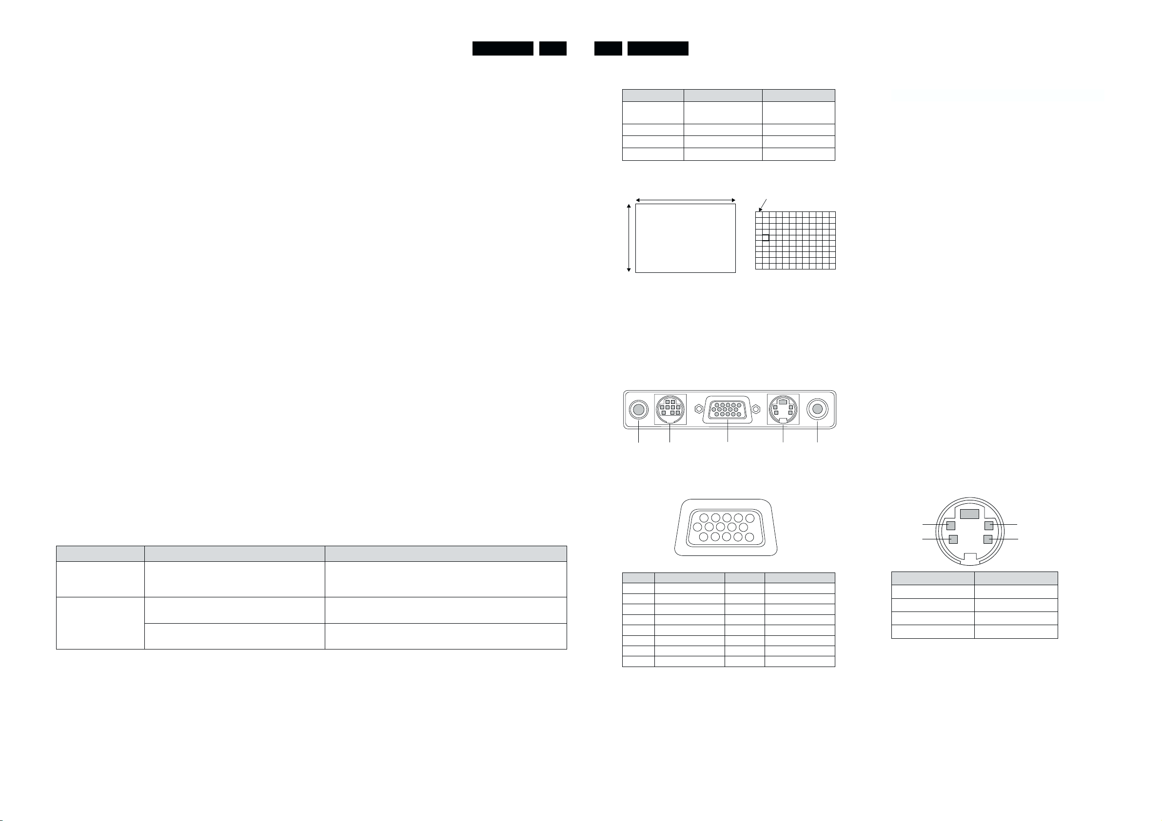
2.2 DMD Chip
Product type LC5241 LC5231
Number of
pixels
Size 0.67 inches 0.67 inches
A 1024 pixels 800 pixels
B 768 pixels 600 pixels
B
1024 (horizontal) x
768 (Vertical) x 1
A
IMAGE
2.3 Input termina
1. AUDIO IN (stereo mini-jack)
2. Mouse output terminal (mini-DIN9pin)
3. RGB/Y CbCr IN (miniD-SUB15pin)
4. S-VIDEO IN (S-video terminal)
5. VIDEO IN (video RCA x 1)
11 121314
6
7
234
1
3
15
98
10
5
21
Relationship between RGB input terminal and signal
Pin No. Single Pin No. Single
1 Red 9 No Connection
2 Green 10 Digital GND
3 Blue 11 GND
4 GND 12 SDA
5 GND 13 Horizontal Sync
6 Red GND 14 Vertical Sync
7 Green GND 15 SCL
8 Blue GND
800 (horizontal) x
600(Vertical) x 1
1 pixel
54
Relationship between S-video terminal and signal.
12
4
Pin No. Single
1 GND
2 GND
3 Luminance signal
4 Chrominance signal
3
PCS 107 322 PCS 107 323
Page 3
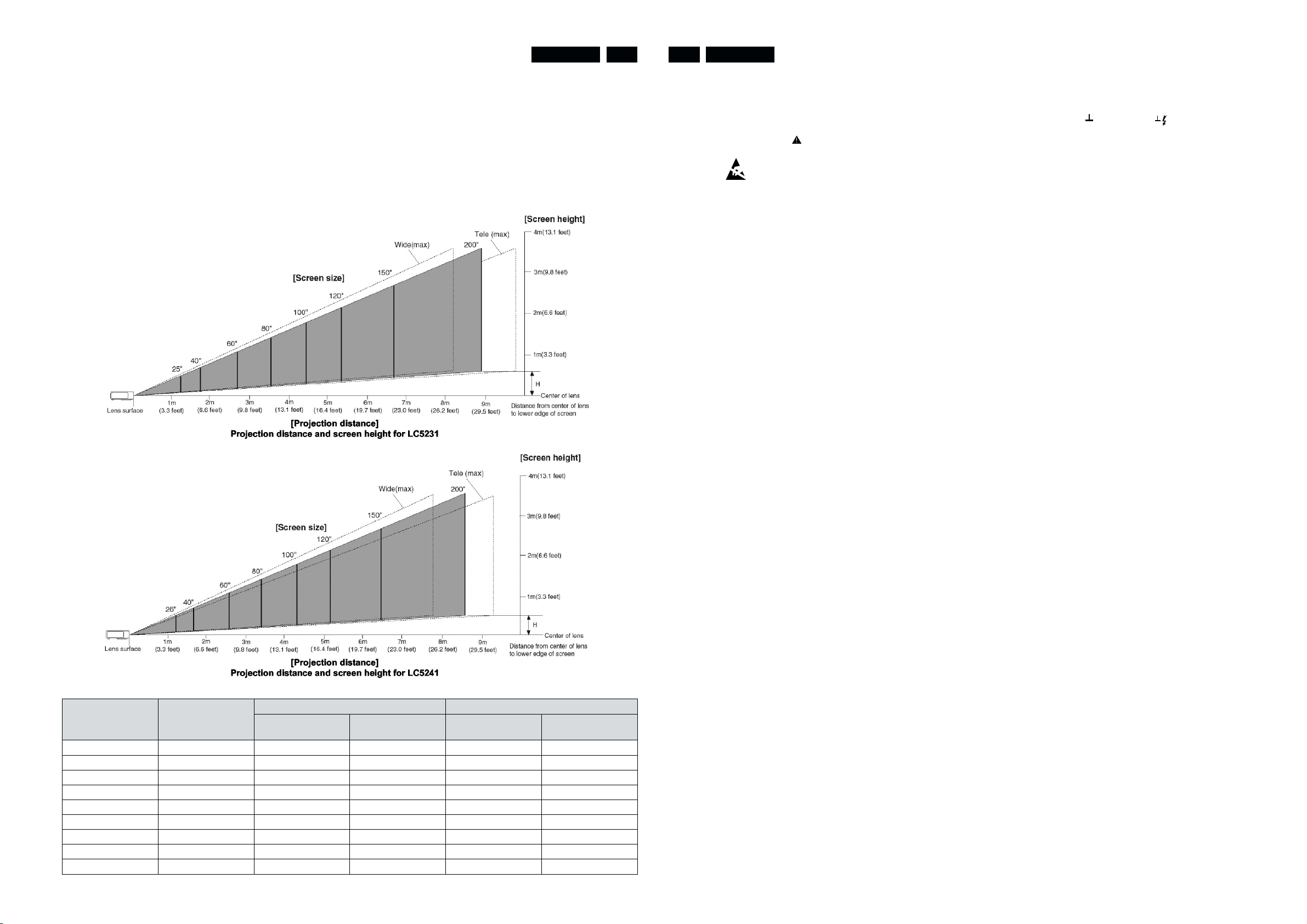
2.4 Projection Size and Projection Distance
There is an error of ±5% for the design value.
•
The horizontal projection position is left-right symmetrical
•
with the lens in the center.
When bright light enters the remote control
•
light-intercepting section, it might not be possible to use
the remote control. Be careful when locating the unit near
lighting.
LC5231/5241 LC5231/52412-3 3-1
The projection distances for correct focus (focal point) are
•
the following values from the lens surface.
LC5231: 1.2 m ~ 9.8 m
LC5241: 1.2 m ~ 9.4 m
Set within this range.
This diagram expresses the projection distance and screen size for
Tele (smaller screen) and Wide (larger screen) positions of the zoom
lens.
3. Warnings & Notes
Warnings
1.
Safety regulations require that the unit should be returned in
its original condition and that components identical to the
original components are used. The safety components are
indicated by the symbol .
2. ESD
All ICs and many other semiconductors are sensitive to
electrostatic discharges (ESD). Careless handling during
repair can drastically shorten the life. Make sure that during
repair you are connected by a pulse band with resistance to
the same potential as the earth of the unit. Keep components
and tools also at this same potential.
3. When repairing a unit, always connect it to the mains voltage
via an isolating transformer.
The lamp supply and the lamp housing are not mains isolated.
4. Be careful when taking measurements in the high-voltage
section.
5. Never replace modules or other components while the unit is
switched on.
Notes
1.
The direct voltages and oscillograms should be measured
with regard to earth ( ), or hot earth ( ) as this is called.
2. The semiconductors indicated in the circuit diagram and in
the parts lists are completely interchangeable per position
with the semiconductors in the unit, irrespective of the type
indication on these semiconductors.
Screen
Normal value(inches
25 50.8 x 38.1 1.20 7.6 - -
26 52.8 x 39.6 1.22 7.6 1.2 6.8
40 81.3 x 61.0 1.6 ~ 1.9 12.0 1.5 ~ 1.9 10.4
60 121.9 x 91.4 2.4 ~ 2.9 18.0 2.3 ~ 2.8 15.5
80 162.6 x 121.9 3.2 ~ 3.9 23.9 3.1 ~ 3.7 20.7
100 203.2 x 152.4 4.1 ~ 4.9 29.9 3.9 ~ 4.7 25.9
120 243.8 x 182.9 4.9 ~ 5.9 35.9 4.7 ~ 5.6 31.1
150 304.8 x 228.6 6.1 ~ 7.4 44.9 5.9~ 7.1 38.9
200 406.4 x 304.8 8.2 ~ 9.8 59.9 7.9 ~ 9.4 51.8
Screen size
Width x Vertical
LC5231 LC5241
Projection distance
(m)Wide ~ Tele
Dimension H (cm)
Projection distance
(m)Wide ~ Tele
Dimension H (cm)
6. When making settings, use plastic rather than metal tools.
This will prevent any short circuits and the danger of a circuit
becoming unstable.
7. After repair the wiring should be fastened once more in the
cable clamps for this purpose.
8. In order to prevent measuring errors, the heat sinks should not
be used as reference points for measurements.
9. Various parts get hot during operation. Please ensure that
they are cooled down before servicing.
10. The lighthouse (optical part) is extremely sensitive to dust.
This part should only be opened in a dust-free environment
(class 100 according to the US federal standard 209).
PCS 107 324 PCS 107 325
Page 4
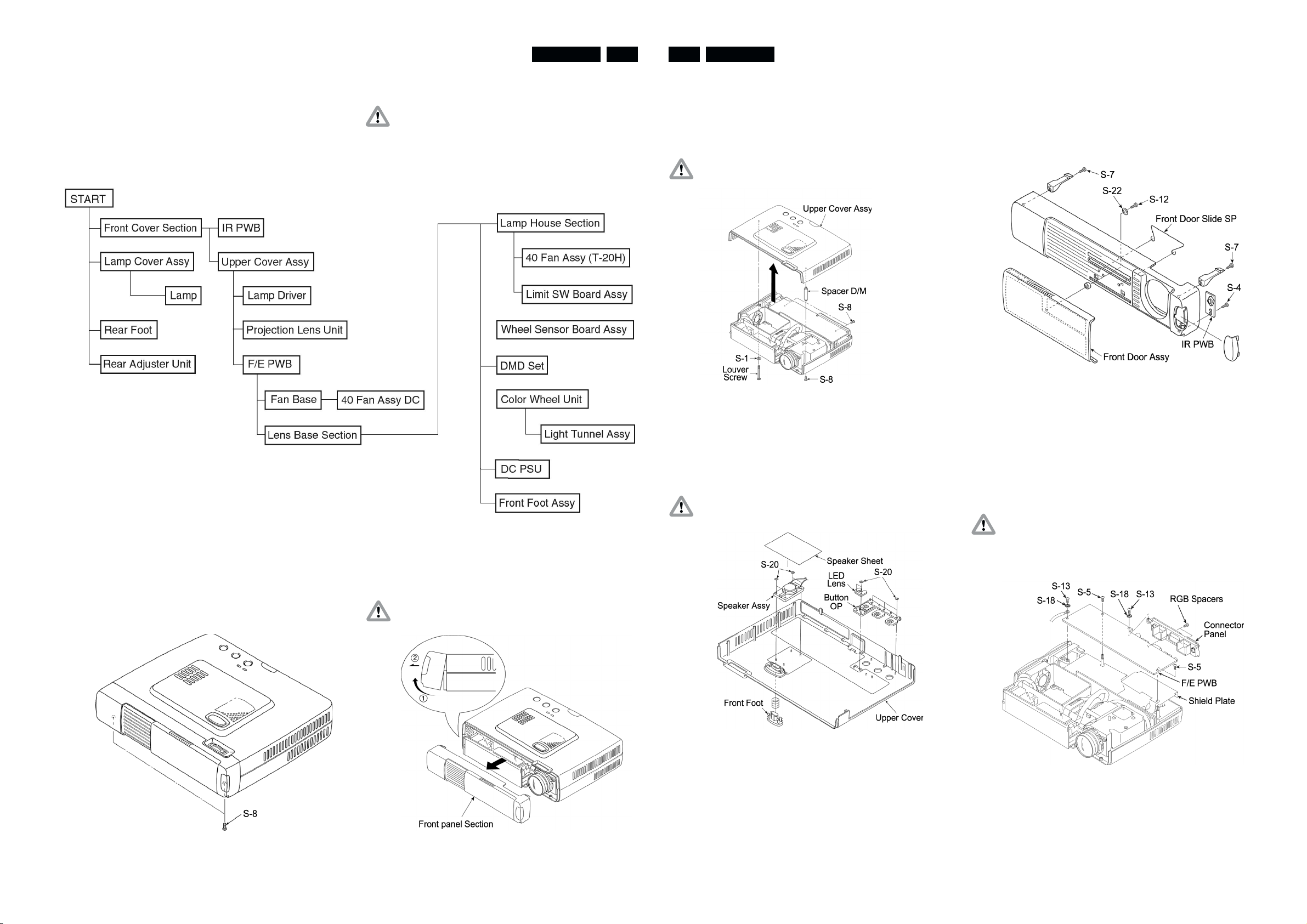
4. Mechanical instructions
LC5231/5241 LC5231/52414-1 4-2
4.1 Preparation and Caution
Tools be prepared:
1. Phillips screwdrivers Nos. 1 and 2.
2. Slotted head screwdriver
3. Electrostatic elimination wrist band
4. Hexagonal wrench (width across flats : 5 mm)
4.3 Disassembly and Assembly
Remove the front panel section (See Figs 1, 1-A).
1. Remove the screws shown in Fig 1 (S-8: 2 screws).
4.2 Disassembly and Assembly order
Cautions
1. When removing the lamp driver, remove the lamp
beforehand.
2. When removing the DC power unit, remove the fan base
beforehand.
2. Remove the front panel section as shown in Fig 1-A.
Remove the upper cover assy (see Fig 2).
1. Remove the three S-8 screws and remove the Louver
Screws.
2. Lift up the Upper Cover Assy and remove the connector
(POSP) of the speaker assy from the F/E PWB.
Caution: When lifting up the Upper Cover Assy, be careful
not to pull the cable of the Speaker Assy.
Fig. 2
Remove the Speaker Assy and buttons (see Fig 3).
1. Peel off the Speaker Sheet.
2. Remove the S-20 bush nut.
3. Push the catch down to remove the front foot knob.
Caution: After replacing the Speaker Assy, be sure to
attach the Speaker Sheet.
Disassembling the front panel section (see Fig 4)
1. Remove the S-12 screw.
2. Remove the Front Door Assy.
3. Remove the IR PWB (one S-4 screw).
4. Remove the left and right front hooks (one S-7 screw
each).
Fig. 4
Remove the F/E PWB (see Fig 5).
1. Remove the cables (connectors: PORM, PODC, PODB,
POLA, POLB, POFA, POFB) from the F/E PWB.
2. Remove the two S-5 screws and one S-13 screw.
3. Remove the cable (POPA) from the F/E PWB.
4. Remove the S-13 screw and two spacer RGBs.
5. Remove the Connector Panel.
Caution: Be careful not to forget to insert the F/E PWB
Shield between the F/E PWB and the DC PSU
(insulation sheet DC 1,2).
Be careful that the F/E PWB Shield does not get
caught between the sheet DCs 1 and 2.
Fig. 1
Caution: When removing the front panel section, be careful
to disconnect the IR Cable Assy.
Fig. 3
Fig. 5
Fig. 1A
PCS 107 326 PCS 107 327
Page 5
LC5231/5241 LC5231/52414-3 4-4
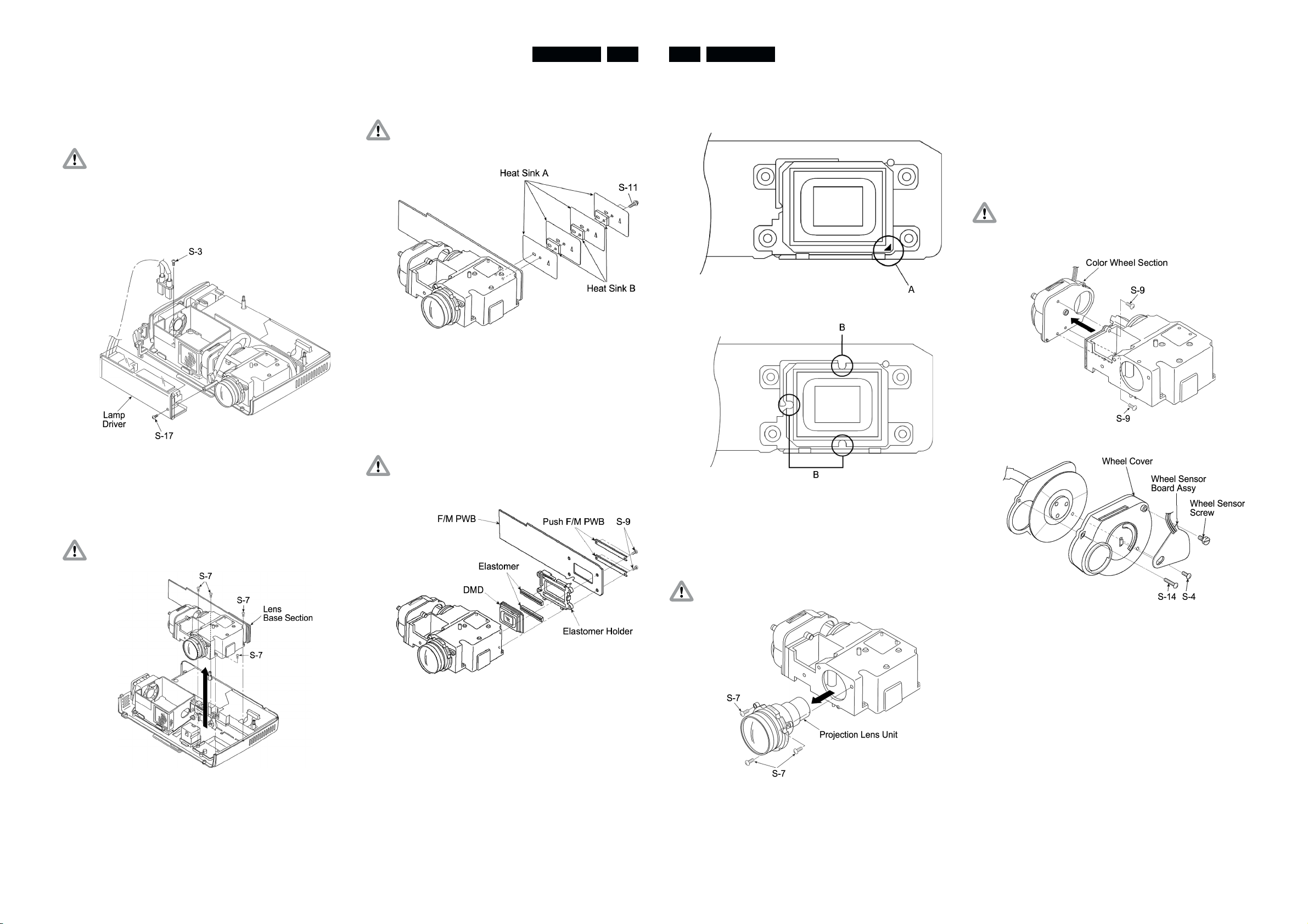
Remove the Lamp Driver (see Fig 6).
1. Remove the S-3 and the S-17 screws (one of each).
2. Remove the cable from the power source
(connector: CN1).
Caution: If the lamp is connected, it is not possible to
remove the Lamp driver. Remove the lamp
beforehand. Be sure to attach the Radiation
Sheet L/D to the Lamp Driver and Insulate Sheet
L/D. Be careful about wiring of the cables for the
Lamp Driver O so that it does not get caught
between the Lamp House Assy and Upper Cover
Assy.
Remove the lens base section (see Fig 7).
1. Remove the four S-7 screws.
2. Remove the lens base section.
Caution: When attaching or removing the lens base, be
careful of the cable.
Fig. 6
Remove the heat sink (see Fig 8).
1. Remove the two S-11 screws.
Caution: Be careful about the heat sink attachment
position.
Fig. 8
Remove DMD set (see Fig 9).
1. Remove the four S-9 screws.
2. Remove the F/M retainer and remove the DMD set from
the lens base section.
Caution: Soiling and dust on the DMD, elastomer or F/M
PWB terminals can have a direct influence on the
image. Be careful during handling.
DMD Chip Attachment Direction (See Figs 10, 11)
1. The attachment direction of the DMD chip differs for XGA
and SVGA. For XGA see FIG 10. For SVGA see FIG 11
Fig. 10
Fig. 11
Remove the Projection Lens Unit (see Fig 12).
1. Remove the three S-7 screws retaining the Projection
Lens Unit.
Remove the color wheel section (see Figs 13, 14).
1. Remove the three S-9 screws retaining the color wheel
section.
2. Remove the S-14 screw and S-4 screw.
3. Remove the Wheel Cover from the Color Wheel Unit.
4. Remove the Wheel Sensor Screw.
5. Remove the Wheel Sensor Board Assy from the Wheel
Cover.
Caution: When removing the color wheel section, be
careful not to touch or damage the Condenser
Lens Assy.
Fig. 13
Fig. 7
Caution: When assembling, be careful not to damage the
mirrors on the lens base interior.
Fig. 14
Fig. 9
Fig. 12
PCS 107 328 PCS 107 329
Page 6
LC5231/5241 LC5231/52414-5 5-1
5. Block diagrams, Wiring diagram
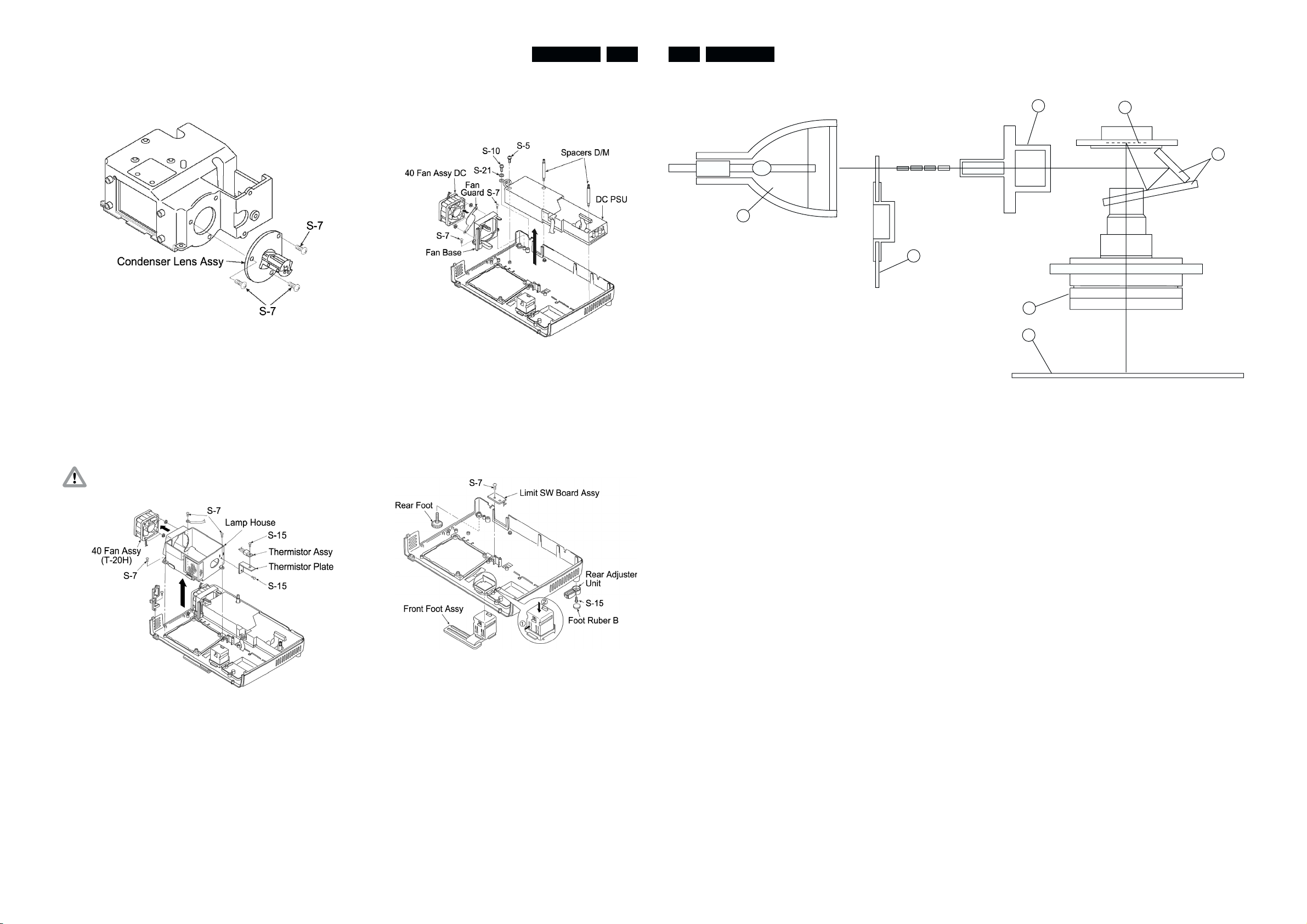
Remove the Condenser Lens Assy (see Fig 15).
1. Remove the three S-7 screws retaining the Condenser
Lens Assy.
Fig. 15
Remove the lamp house section (see Fig 16).
1. Remove the three S-7 screws retaining the lamp house
section.
2. Remove the S-15 screw retaining the Thermistor Plate.
3. Remove the S-15 screw retaining the Thermistor Assy.
4. Remove the 40 Fan Assy (40 Fan) from the Lamp House
Assy.
Caution: Be careful of the 40 FAN wiring method and
attachment direction.
Remove the power section (see Fig 17).
1. Remove the two S-7 screws retaining the fan base.
2. Remove the S-5, 10 screw retaining the DC PSU assy
and the two spacer D/M
Fig. 17
Remove the front and rear foot, etc. (see Fig 18).
1. Push down the catches shown by (1) and (2) in the figure
and remove the Front Foot Assy.
2. Remove the S-7 screw retaining the Limit SW Board Assy.
3. Remove the Foot Rubber B.
4. Remove the S-23 screws retaining the Rear Adjuster Unit.
5.1 Optical system principle block diagram
1
Description of function
1. Lamp
Light source: Flashes 300 times per second as AC lamp.
2. RGBW color wheel
Divides light into the RGBW components using color filters.
The W component allows a bright white to be reproduced.
A rotation detecting sensor is used to time the lamp which is
turned OFF at the color filter seam.
The maximum speed is 7,200 rpm.
3. Condenser lens and light tunnel
Collects light divided into RGBW components by the color
filter and projects them on the effective surface of reflection
mirror 1.
Use of the light tunnel lens increases the peripheral intensity
of illumination. It reduces the difference of brightness between
the screen center and periphery, reproduces a clear view of
even the corners of the screen.
G B R W
2
3
5
6
7
4. Reflection mirror 1 and 2
Reflects light beamed on the mirror effective surface, to the
DMD effective surface.
5. DMD chip
Reflects the light by switching on and OFF according to the
input source at the ratio of color components for each dot.
6. Projection lens
Enlarges and projects light from the DMD.
7. Screen
The projected light (RGBW components) forms a picture with
colors synthesized through afterglow.
4
Fig. 16
Fig. 18
PCS 107 330 PCS 107 331
Page 7

5.2 Wiring diagram
SPEAKER
PORM
POPA
POSP
CN20
IR-SENSOR
LC5231/5241 LC5231/52415-2 5-3
CN2
CN1
6. Directions for use
F/E PWB
PODC
PODB
POLB
POLA
POFA POFB
DC
POWER
SUPPLY
UNIT
LAMP-SW
TEMPERATURE-SENSOR
WHEEL-SENSOR
LAMP
DRIVER
LAMP
LAMP-FAN
DC-PSU-FAN
J2
F/M PWB
PCS 107 332 PCS 107 333
Page 8

LC5231/5241 LC5231/52416-2 6-3
PCS 107 334 PCS 107 335
Page 9

LC5231/5241 LC5231/52416-4 6-5
PCS 107 336 PCS 107 337
Page 10

LC5231/5241 LC5231/52416-6 6-7
PCS 107 338 PCS 107 339
Page 11

LC5231/5241 LC5231/52416-8 6-9
PCS 107 340 PCS 107 341
Page 12

LC5231/5241 LC5231/52416-10 6-11
PCS 107 342 PCS 107 343
Page 13

LC5231/5241 LC5231/52416-12 7-1
7. Alignments & Protections
7-1. Color wheel sensor adjustment
Adjustment is required in the following cases:
1. After color wheel unit replacement
2. After color wheel sensor replacement
3. After optical engine unit replacement (to be adjusted if
failure is found by inspection)
4. After F/E board replacement (to be adjusted if failure is
found by inspection)
Preparation
1. PC (Windows95/98-based computer)
2. RGB cable
3. Special-purpose software (white.exe)
4. Wrench (5 mm)
Caution: When adjusting be careful not to touch hot areas
such as the lamp. Also be careful not to short the
substrates or other parts.
7-2. Lamp replacement
Preparation
1. A cushion to prevent the main unit fro being damaged
when it is placed in a reverse position
2. A Phillips screwdriver No.1
Cautions for lamp replacement and handling
1. Before starting lamp replacement, be sure to unplug
the power supply. (Otherwise, electric shock may
occur.)
2. Start lamp replacement after making sure that the
lamp is cooled.(Otherwise, fire may occur.)
3. Do not allow the lamp to be exposed to strong shock
or vibration.(Otherwise, damage or injury may occur.)
4. Do not disassemble the lamp.
Lamp replacement
1) Remove the lamp cover fastening screw.
Fig 1
Procedure
1. Make adjust when the upper and front cover has been
removed.
2. Connect between the projector and PC. (mode RGB)
3. Start the special-purpose software with the PC.
4. Press the “6" key on the keyboard. After the Figure
above (Fig. 1) is displayed, press the ”R" key to
display the red picture. Then check the image. Check
other than red, too (*1).
5. If there is any portion on the screen that does not turn
red, loosen the wheel screw and adjust the wheel
sensor in Fig. 2 in the vertical direction and fasten it at
a position where there is no color misalignment.
6. After adjustment, press the “Q” key on the keyboard to
terminate the software.
Wheel sensor
2) Remove the lamp cover.
3) Remove three lamp cartridge fastening screws
Note: *1. The basic black-and-white patterns are registered on
PCS 107 344 PCS 107 345
Wheel screw
the number keys (0-9), and colors can be changed
with the following letter keys:
W (white), K (black), R (red), G (green), B (blue), M
(magenta) and C (cyan)
Fig. 2
Page 14

LC5231/5241 LC5231/52417-2 7-3
4) Hold the handle and take out the lamp housing.
5) Install a new lamp housing.
6) Fasten three lamp housing fastening screws.
8) Reset the lamp time.
After the Information Menu appears, select “Reset Lamp
Time” and press the ENTER button.
To reset, press the ENTER button. To quit, press the
CANCEL button.
MENU INFORMATION
RESET
LAMP USAGE HOURS RESET
9) When power cuts off after lamp was used over 1100
hours. After replacing the lamp housing, connect the
power cord and set in standby. Hold down the unit
SOURCE and AUTO buttons simultaneously for at least
5 seconds.
7.3. Protections
7.3-1. Internal Temperature Detection
There is a thermostat in the lamp housing, which switches off
the lamp when thermostat temperature has reached 110°C or
more (See status LED overview).
7.3-2. Lamp Unit and Interlock Switch
If the lamp cover is not mounted, the lamp does not turn on
(See status LED overview).
7.3-3. Status LED Overview
Status LED overview Meaning Solution
OFF (lamp off) Normal
ON (lamp on) The lamp has been used in excess of 1,000
hours
Flashing at intervals of one second
The lamp is not installed correctly. Install the lamp correctly
Replace with a new lamp and reset the lamp
usage time
(ON for 0.5 sec./OFF for 0.5 sec.)
Flashing at intervals of 4 seconds
(ON for 2 sec./OFF for 2 sec.)
Internal temperature is too high.
The temperature protector has been triggered
If the room temperature is high, move the
projector to a cooler location.
If the temperature inside the projector is high,
check the cooling fan vents and bottom vents,
and clean and remove any substance with which
these vents are clogged.
Power may not be turned on if you switch ON the
main power switch immediately after the
temperature protector has been triggered and the
Wait for one minute; then turn ON the switch.
main power switch has been turned OFF.
Flashing at intervals of 8 seconds
(ON for 4 sec./OFF for 4 sec.)
Flashing at intervals of 12 seconds
(ON for 6 sec./OFF for 6 sec.)
The lamp lighting voltage failure detection
protector has been triggered.
The fan is stopped Inspect the exhaust fan
The lamp fails to light up
Wait for one minute; then turn ON power.
Wait for one minute; then turn it ON. If this does
not solve the problem, see trouble shooting.
7) Install the lamp cover and fasten it with fastening
screws
The Status LED lamp flashes if the lamp is not turned on.
The flashing cycle allows you to trace the cause of the trouble
(See the drawing below and the table on the next page).
Status LED
POWER
POWER
STATUS
SOURCE
AUTO
7.4 Trouble shooting
Checking Operations
By checking operations during normal usage time it is
possible to carry out judgments on malfunctions to a certain
extent. Carry out the following checks before disassembling
the equipment.
Insert the Mains cord.
Does the Power LED
light (orange)?
YES
Does the Status LED
light/blink (red)?
NO
NO
YES
Faulty power cord.
Cable (POPA) is
disconnected or broken.
DC PSU is malfunctioning.
The F/E PWB is malfunctioning.
Status LED lights : Lamp usage time has exceeded 1,100 hours.
Status LED blinks 0.5 seconds : Lamp Cover Assy is not inserted.
: Cable (POLB) is disconnected.
: Limit SW Board malfunction.
Status LED blinks four seconds : Cable (POFA) is disconnected.
: 40 Fan (DC) malfunctioning (does not rotate).
PCS 107 346 PCS 107 347
Page 15

LC5231/5241 LC5231/52417-4 7-5
Turn the power ON.
Does the status LED
blink (red)?
NO
Is the lamp lit?
YES
Is the power LED
(green) on?
YES
NO
NO
Status LED blinks two seconds : Cable (POLB) is disconnected.
/thermistor Assy malfunctioning.
: Temperature protector is operating.
: DC PSU malfunctioning.
Status LED blinks four seconds : Cable (POLB) is disconnected.
: 40 Fan (T-20H) malfunctioning (does not rotate).
Status LED blinks six seconds : Lamp operation sound (ignition sound).
- Lamp lighting failure.
- Lamp malfunction (broken, non-lighting lamp).
: No lamp operation sound (ignition sound).
- Cable (PODC) is disconnected/broken.
- Cable (CN1) is disconnected/broken.
- Lamp Driver is malfunctioning.
- DC PSU is malfunctioning.
: Color wheel unit does not rotate.
- Cable (J2) is loose.
- Color Wheel Unit malfunction (does not rotate).
- F/M PWB malfunction.
F/E PWB is malfunctioning.
F/E PWB is malfunctioning.
Confirmation with
non-signal state (blue back).
Still dark when
1 minute has elapsed
after lighting?
(check brightness)
NO
Press "menu".
Is the menu displayed?
YES
Connect the RGB/Video/
S-Video/Components.
Does the RGB image
appear?
YES
YES
NO
NO
Lamp deterioration (malfunction/usage time).
Lamp Driver malfunction.
DMD malfunction.
Remote Controller Set malfunction/dead battery/
outside usage range.
Cable (PORM) is disconnected or broken.
F/E PWB is malfunctioning.
F/E PWB is malfunctioning.
Setting on PC side (external output setting/resolution, etc.)
VGA cable is malfunctioning (breakage/pins broken).
YES
Is the PHILIPS logo screen
displayed?
YES
Go to next page.
NO
Cable (PODB) is loose.
Wheel Sensor Board Assy malfunction.
F/E PWB malfunction.
Poor connection between F/E PWB and
F/M PWB connection connector.
Does the
video/S-Video screen
appear?
YES
Is there sound?
YES
Check the projection screen
(Check with all
black/white screens
with RGB connection.
Also possible with
blue back (non-signal state).
Are
abnormalities noticeable
on projection screen?
NO
NO
YES
F/E PWB is malfunctioning.
Cables are broken.
Problem on player side (breakdown, etc.)
Cable (POSP) is loose.
Speaker Assy is malfunctioning.
F/E PWB is malfunctioning.
Black lines on screen (horizontal, vertical) : DMD malfunction.
Missing pixels : DMD malfunction.
(missing white : 1 or more,
missing black : 4 or more (SVGA)
: 5 or more (XGA),
or sequence of 2 or more missing pixels).
PCS 107 348 PCS 107 349
Shadow on screen : Dirt on DMD/Lens Unit surface.
NO
Normal Operation.
Page 16

LC5231/5241 LC5231/52417-6 7-7
7.5 Cleaning
Carry out cleaning of the main unit and interior when replacing the
lamp or making inspections.
1) Cleaning the projection lens unit
When dust and fingerprints, etc. are on the lens surface,
•
use a glass cleaner to remove as shown in the figure at
the right.For fingerprints and other soiling that are difficult
to remove with a dry cloth, use a designated glass
cleaner which has been moistened in water and then use
a dry cloth to dry it off.
The projection lens surface has a special coating.
•
Do not use detergents or solvents on the surface.
2) Cleaning the color wheel unit
The color filter is made of thin glass. Be very careful
•
when handling the filter.
In case of fingerprints, etc. on the surface, clean in
•
the same way as the projection lens unit as described in
item 1). Do not use detergents as this could cause
peeling of the color filter.
3) Cleaning the DMD
The DMD surface is glass and can be cleaned. However,
•
avoid scratches as these can have a direct influence on
the image.
In case of dust on the DMD surface use an air cleaner
•
(with a device to prevent static, if possible) to clean off the
surface.
• In case of fingerprints, etc., add a small amount of water
to the designated glass cleaner and wipe off in one
direction.Then use the designated dry glass cleaner to
wipe off in the same direction.
• Do not use absolute alcohol or other substances that
could leave streaks after drying.
Notes:
4) Cleaning the Reflecting Mirror
• Be careful not to touch the reflecting mirror. The surface
is composed of vapor deposition silver and touching it
directly with the hands can lead to burnishing.
•
Do not clean other than with air.
5) Cleaning the Main Unit
•
Clean with a soft fuzz-free cloth. In case of severe soiling,
use a well-wrung cloth dipped in a neutral agent to
remove soiling and then finish with a dry cloth.
•
Do not clean with thinner, benzene or similar agents as
this could lead to deterioration or peeling of paint.
•
In case of dust in suction or exhaust holes or the interior,
disassemble the main unit and use air to remove the dust
from the inside.
PCS 107 350 PCS 107 351
Page 17

8. Parts list
LC5231/5241 LC5231/52418-1 8-2
Upper Cover Section
1 Upper Cover Assy 9965 000 12078
2 Speaker Assy 9965 000 07137
3 Speaker Sheet No Spare part
4 Louver Screw 9965 000 07302
5 Front Panel 9965 000 12055
6 IR PWB 9965 000 07170
7 IR Cable Assy 9965 000 07301
8 Front Hook 1 9965 000 07171
9 Front Hook 2 9965 000 07172
10 Slider Roller 9965 000 07299
11 Front Door Slide Spring 9965 000 12084
12 Front Door Assy 9965 000 07278
PWB Section
13 F/E PWB (XGA LC5241) 9965 000 12091
13 F/E PWB (SVGA LC5231) 9965 000 12056
14 Connector Panel 9965 000 12063
15 Connector Sheet 9965 000 12064
16 Spacer RGB 9965 000 07306
17 Lens Base Urethane Form 9965 000 07307
18 Lamp Driver Stud 9965 000 07173
19 Limit SW Board 9965 000 07142
20 Lamp Driver 9965 000 12065
21 Insulate Sheet L/D 9965 000 12079
22 Radiation Sheet L/D 9965 000 07309
PCS 107 352 PCS 107 353
23 Lamp Driver Lock Base 9965 000 07174
24 Louver Panel 9965 000 12066
25 Lamp House Assy 9965 000 07145
26 Thermister Plate 9965 000 07310
27 Thermister Assy 9965 000 07146
28 40Fan Assy T-20H 9965 000 12067
29 40Fan Assy DC 9965 000 12068
30 Fan Base 9965 000 07175
31 Core 9965 000 07314
32 Fan Fence 9965 000 07315
33 GND Cable 9965 000 07316
34 Lamp Sync Cable Assy 9965 000 07433
35 F/E PWB Shield 9965 000 12085
Page 18

LC5231/5241 LC5231/52418-3 8-4
Lower Cover Section
36 Lower Cover 9965 000 12069
37 Inlet Spacer 9965 000 07317
38 Spacer D/M 9965 000 07305
39 Spacer Tube 9965 000 12086
40 DC PSU 9965 000 12070
41 Insulate Sheet DC-1 9965 000 07318
42 Insulate Sheet DC-2 9965 000 07319
43 Rear Foot 9965 000 07151
44 Rear Foot Rubber 9965 000 07152
45 Rear Adjuster Unit 9965 000 12087
46 Foot Rubber B 9965 000 12088
47 Front Foot 9965 000 07153
48 Lamp Cover Assy 9965 000 12089
48a Replacement Lamp 8670 931 19009
Optical Section
50 Insulate Sheet L/B 9965 000 07320
51 Lens Unit 9965 000 12072
52 Condenser Lens Assy 9965 000 07156
53 Color Wheel Unit 9965 000 12073
54 Wheel Cover 9965 000 07176
55 Rubber Sheet 9965 000 07177
56 Wheel Sensor Board Assy 9965 000 07157
57 Wheel Sensor Screw 9965 000 07321
58 Sticker SD-10 9965 000 07322
59 DMD Set (XGA LC5241) 9965 000 12092
PCS 107 354 PCS 107 355
59 DMD Set (SVGA LC5231) 9965 000 12074
60 DMD (XGA LC5241) No Spare part
60 DMD (SVGA LC5231) No Spare part
61 Elastomer No Spare part
62 Elastomer Holder No Spare part
63 F/M PWB XGA LC5241 No Spare part
63 F/M PWB SVGA LC5231 No Spare part
64 Push F/M PWB 9965 000 07323
65 Gasket (DMD) 9965 000 12090
66 Heat Sink A 9965 000 07324
67 Heat Sink B 9965 000 07325
Page 19

LC5231/5241 LC5231/52418-5 8-6
Accessories Section
68 Carton (XGA LC5241) 9965 000 07178
68 Carton (SVGA LC5231) 9965 000 12076
69 Packing 9965 000 07179
70 Wrapping Material (Machine) 9965 000 07180
71 Accessory Box 9965 000 07181
72 Quick Reference Guide No Spare part
73 Operation Manual (CD-ROM) 9965 000 12075
74 Warranty Card No Spare part
75 Warranty Card Envelope EU No Spare part
76 Warranty Card Envelope USA No Spare part
77 Inlay Sheet No Spare part
78 Carrying Case 9965 000 07183
79 Accessory Pad 9965 000 07330
80 Cable Case 9965 000 07184
81 PS/2 Mouse Cable 9965 000 07168
82 S-Video Cable (1m) 9965 000 07165
83 Video Cable (1P 1m) 9965 000 07163
84 Mini Jack Cable (1m) 9965 000 07167
85 USB Mouse Cable 9965 000 07169
86 Audio Adapter 9965 000 07164
87 Remote Controller 9965 000 07159
88 AAA Battery No Spare part
89 Power Cable (1.8m) UL 9965 000 07161
90 Power Cable (1.8m) CEE 9965 000 07162
91 RGB Cable (1m) 9965 000 07166
92 Desiccant (30g) No Spare part
93 Out Carton No Spare part
94 Bag(Manual,Accessory) 9965 000 12077
PCS 107 356 PCS 107 357
Label Section
95 Rating Label (XGA LC5241) 9965 000 12093
95 Rating Label (SVGA LC5231) 9965 000 12080
96 Caution Seal A (Hot)-C 9965 000 12081
97 Caution Seal C (Lens)-C 9965 000 12082
98 Lamp Caution Seal A-C No Spare part
99 Loge Mark 9965 000 07185
100 POP Label (XGA LC5241) No Spare part
 Loading...