

Page 1
1-1 LC5131/5141
1. Safety guidelines
Portable LCD projector
IMPORTANT SAFETY NOTICE
Proper service and repair is important to the safe, reliable operation of all Philips Consumer Electronics Company** Equipment.
The service procedures recommended by Philips and described in this service manual are effective methods of performing
service operations. Some of these service operations require the use of tools specially designed for the purpose. The special
tools should be used when and as recommended.
It is important to note that this manual contains various CAUTIONS and NOTICES which should be carefully read in order to
minimize the risk of personal injury to service personnel. The possibility exists that improper service methods may damage the
equipment. It also is important to understand that these CAUTIONS and NOTICES ARE NOT EXHAUSTIVE. Philips could not
possibly know, evaluate and advise the service trade of all conceivable ways in which service might be done or of the possible
hazardous consequences of each way. Consequently, Philips has not undertaken any such broad evaluation. Accordingly, a
servicer who uses a service procedure or tool which is not recommended by Philips must first satisfy himself thoroughly that
neither his safety nor the safe operation of the equipment will be jeopardized by the service method selected.
** Hereafter throughout this manual, Philips Consumer Electronics Company will be referred to as Philips.
WARNING
Critical components having special safety characteristics are identified with an by the Ref. No. in the parts list
and enclosed within a broken line* (where several critical components are grouped in one area) along with the
safety symbol on the schematics or exploded views.
Use of substitute replacement parts which do not have the same specified safety characteristics may create shock,
fire, or other hazards.
Standby
/O
n
In
p
u
S
t
ta
tus
Au
to im
age
LC5131/00
LC5141/00
UGO S-light/X-light
Under no circumstances should the original design be modified or altered without written permission from Philips.
Philips assumes no liability, express or implied, arising out of any unauthorized modification of design. Servicer
assumes all liability.
* Broken Line
Contents Page
1. Safety guidelines 1-1
2. Specifications 2-1
3. Warnings & Notes 3-1
4. Mechanical instructions 4-1
5. Block diagrams, Wiring diagram & Oscillograms 5-1
6. Directions for use 7-1
7. Alignments & Protections 8-1
8. Parts lists 9-1
PCS 106 634
Published by Consumer Electronics Printed in The Netherlands©Copyright reserved Subject to modification
PCS 106 633
3122 435 40280
Page 2
2. Specifications
54
3
21
11 121314
15
10
98
7
6
1
234
5
12
3
4
17.3
Height to
screen (H)
Screen
Width
Screen size
(inches in diagonal dimension)
Height
Main unit
Projection distance (L)
o
0
0
1
2
34
56
1
2
3
4
5
(m)
1.2m
2.7m
3.4m
5.1m
6.8m
Projection distance
Center lens
Projection height
36
80
100
150
200
Screen size
(m)
17.3
o
LC5131/5141 2-1 2-2 LC5131/5141
2.1 Product specifications
Package
UGO LC5141/LC5131
:
2.2 DMD Chip
Relationship between S-video terminal and signal.
Remote Control + 2x AAA batteries
UGO UGO
X-lite S-lite
800 ANSI lumens 800 ANSI lumens
XGA resolution SVGA resolution
Compact design - < 2 dm
Ultra lightweight just 1.3 kg
Easy plug&play
Digital picture enhancement
Dimensions; 227 x 48 x 177 mm (WxHxD) < 2 dm
•
Net weight 1.3 kg; ca 2.86 lbs
•
Advanced compatibility for both data and video input;
•
compatible with main notebook computers
High contrast ratio; 800:1 (Full on/off)
•
Digital picture enhance technologies;
•
Digital Zoom (x10), Digital Freeze, Digital
•
Keystone correction
•
Intuitive Graphic User Interface (GUI) for ease of use
•
Auto voltage for safe usage around the world
•
Robust, reliable technical design
•
Suitable for meeting rooms for 2 to 20 people
•
Kensington lock
•
Technical specifications
DMD™
3
1x 0.67" DMD™
:
LC5141 786,432 pixels,Time sequential
(1024x768)
LC5131 480,000 pixels,Time sequential
(800x600)
3
Executions
Optional acc.:New 130 W UHP lamp
Image diagonal size Projection distance
[inch] [meters] [inch] [meters]
37 0,94 47 1,2
60 1,52 79 2,0
80 2,03 106 2,7
100 2,54 134 3,4
120 3,05 161 4,1
150 3,81 201 5,1
200 5,08 268 6,8
Power cord (1,8m) (2 cords,
Continental Europe and USA)
VGA Cable (1m)
PC Audio cable
Mouse cable set; 1m, PS/2 ; 1m, USB
Audio/Video RCA Cable
(1m,Video/Audio stereo)
S-Video cable (1m)
Soft carrying bag
User Guide (8 languages - CD-Rom,
plus Quick Reference Guide)
LC 5141/00 Global product in native XGA
:
LC5131/00 Global product in native SVGA
:
Product type LC5141 LC5131
Number of
pixels
1024 (horizontal) x
768 (Vertical) x 1
Size 0.67 inches 0.67 inches
A 1024 pixels 800 pixels
B 768 pixels 600 pixels
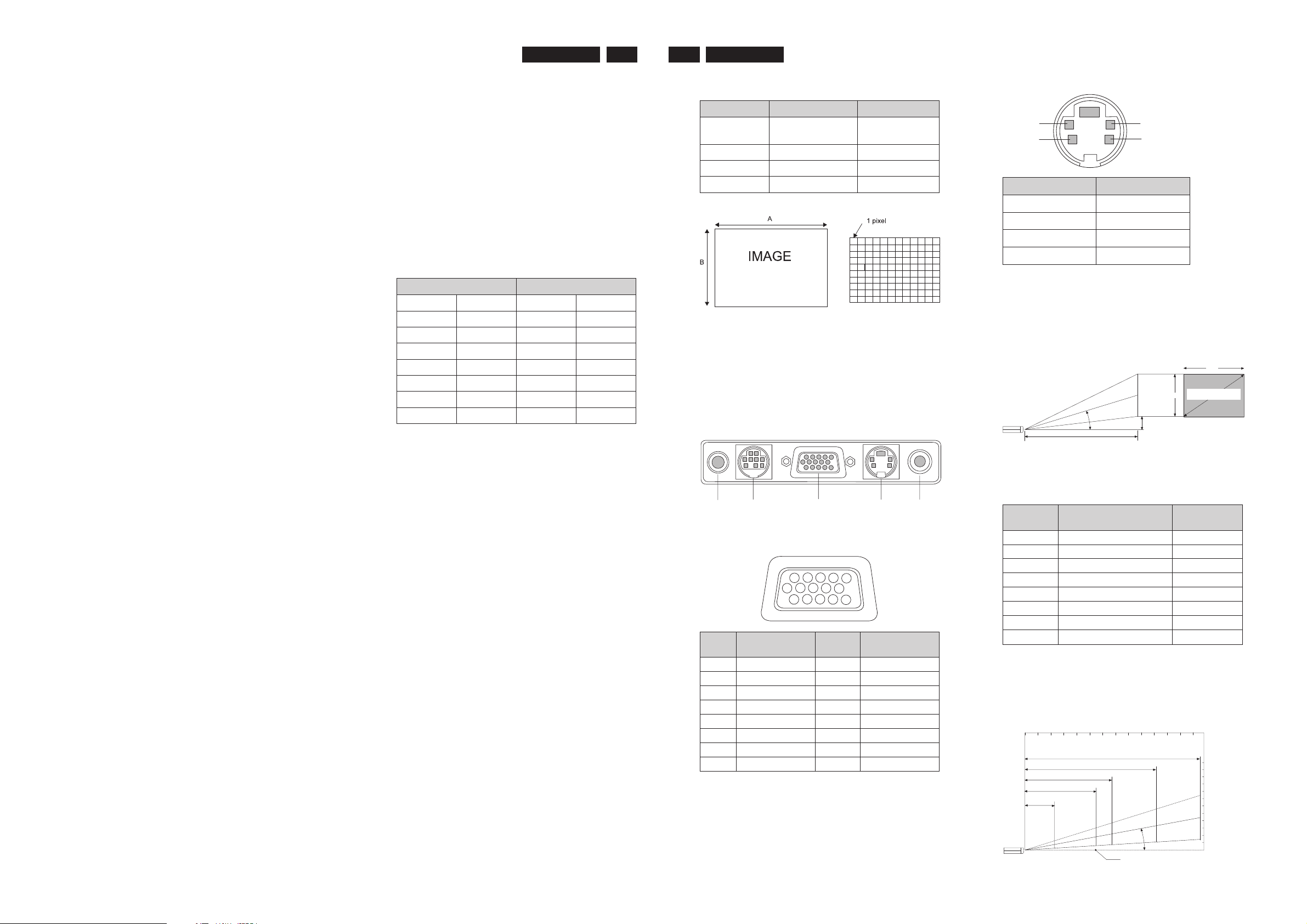
2.3 Input termina
1. AUDIO IN (stereo mini-jack)
2. Mouse output terminal (mini-DIN9pin)
3. RGB/Y CbCr IN (miniD-SUB15pin)
4. S-VIDEO IN (S-video terminal)
5. VIDEO IN (video RCA x 1)
Relationship between RGB input terminal and signal
800 (horizontal) x
600(Vertical) x 1
Pin No. Single
1 GND
2 GND
3 Luminance signal
4 Chrominance signal
2.4 Projection size and projection distance
The projection size ranges from a minimum of 36 inches to a
maximum of 300 inches. The focusing projection distance is
between 1.2 and 6.8 meters from the lens surface. Install
within this range.
Brightness : 800 ANSI lumens
Contrast : 800:1 (Full on/off )
Lamp : 130 W UHP lamp
End user replaceable1000 hours
Lens : F3.0 ;f=23mm
Fixed Focal length; Manual Focus
• Horizontal projection position: Left-right symmetry with
lens in center.
• Vertical projection position (for XGA)
Proj. Dist. 1,2 - 5,8m; Diagonal
(42 - 200)"
Digital features:Digital Zoom (x10), Digital Freeze,
Input signals
Video
:
NTSC 3.85, 4.43 /PAL BG, N, M /Secam
in 4:3 and 16:9 formats
Data
:
PC and Mac compatible, Multi scan
VGA, SVGA, XGA, SXGA via high
advanced scaling technology.
Auto image control Hor. scan rate:
15-91 kHz; Vert. Refresh rate 50-85 Hz.
Power in
Input connections
Video
Data
Mains
Specialities
Dimensions
Net weight
:
:
:
:
:
:
:
110-120 V / 220-240 V; 50/60 Hz; 180 W
S-Video (Y/C DIN)/Video (RCA)/ Stereo
Audio (2x RCA)/ YCbCr
Mini sub-D data (15 pin)/PC Stereo
Audio (M3.5 stereo jack) / Serial mouse
(9pin Mini DIN); USB port / PS/2
Mains input socket (3 pin)
48 mm Ultra Thin Profile
800 : 1 Contrast Ratio
Advanced compression technology for
full automatic adjust multi scan
data input handling, VGA up to SXGA
resolutions to full screen
Intuitive Graphic User Interface (GUI)
for ease of use
Full plug&play compatible (DCC 1 / 2b)
Full Mirror function
Acoustical Noise <39 dBA
227x 48 x 177 mm (WxHxD); <2 dm3
1,3 kg; ca 2,86 lbs
Pin
No.
PCS 106 635 PCS 106 636
Single Pin No. Single
1 Red 9 No Connection
2 Green 10 Digital GND
3 Blue 11 GND
4 GND 12 SDA
5 GND 13 Horizontal Sync
6 Red GND 14 Vertical Sync
7 Green GND 15 SCL
8 Blue GND
Screen
size
Projection distance L m
Dimension
H cm
Inches Meters Millimeters
36 1.2 99
60 2.0 169
80 2.7 225
100 3.4 281
120 4.1 337
150 5.1 422
200 6.8 562
•
These values are based on design values, and their error
is within +/-5%.
Projection distance and projection size
Page 3
3. Warnings & Notes
LC5131/5141 3-1 4-1 LC5131/5141
4. Mechanical Instructions
Warnings
1.
Safety regulations require that the unit should be returned in
its original condition and that components identical to the
original components are used. The safety components are
indicated by the symbol .
2. ESD
All ICs and many other semiconductors are sensitive to
electrostatic discharges (ESD). Careless handling during
repair can drastically shorten the life. Make sure that during
repair you are connected by a pulse band with resistance to
the same potential as the earth of the unit. Keep components
and tools also at this same potential.
3. When repairing a unit, always connect it to the mains voltage
via an isolating transformer.
The lamp supply and the lamp housing are not mains
isolated.
4. Be careful when taking measurements in the high-voltage
section.
5. Never replace modules or other components while the unit is
switched on.
6. When making settings, use plastic rather than metal tools.
This will prevent any short circuits and the danger of a circuit
becoming unstable.
7. After repair the wiring should be fastened once more in the
cable clamps for this purpose.
8. In order to prevent measuring errors, the heat sinks should
not be used as reference points for measurements.
9. The Lamp house and the lamp get hot during operation.
Please ensure that they are cooled down before servicing.
Notes
1.
The direct voltages and oscillograms should be measured
with regard to earth (4), or hot earth (5) as this is called.
2. The semiconductors indicated in the circuit diagram and in the
parts lists are completely interchangeable per position with
the semiconductors in the unit, irrespective of the type
indication on these semiconductors.
4.1 Preparations and Cautions
Items to have on hand:
1. Number 1 and 2 Philip’s head screwdrivers.
2. Precision screwdrivers (Philip’s head and flat head)
3. Wristband to remove static electricity.
Cautions during disassembly and assembly.
1. When carrying out operations remove the power lamp
beforehand.
2. Some parts may still be hot immediately after use. Be
sure all parts have cooled sufficiently before starting
operations.
3. Make sure all parts, screw tightenings and wirings are in
the original position.
4. Cautions have been included concerning areas which
require particular care when handling parts and carrying
out operations. Be sure to observe all cautions.
5. Special parts which are specified for the LC5131/LC5141
models should not be attached to other models.
6. Do not attempt to remodel the equipment.
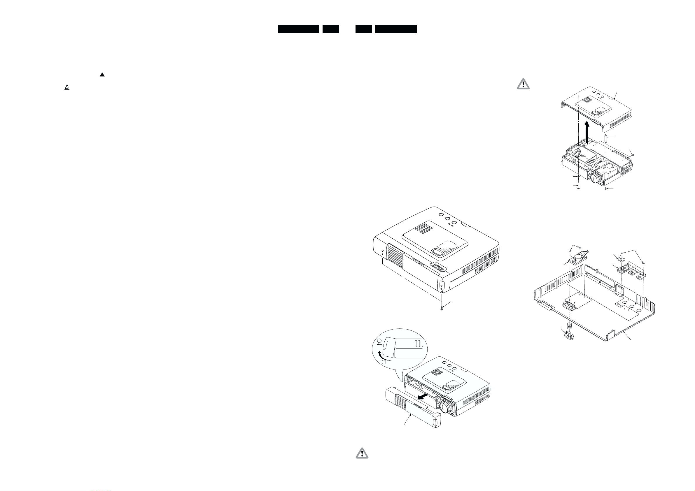
4.2 Disassembly, Assembly
1. Front Panel Section (See Fig 1 and Fig 1-A).
Remove the screws (S-8: 2 screws) as shown in Fig 1.
2. Upper cover Section (See Fig 2)
Remove the screws (S-8, 3 screws, louver screw) as
shown in Fig 2.
Remove the upper cover as shown in Fig 2.
Caution: Be careful not to disconnect or break the speaker
Upper cover
Spacer D/M
S-8
S-1
Louver
screw
Cable
3. Speakers, Buttons, etc. (See Fig 3)
Remove the S-20 as shown in Fig 3 and then remove
the speaker button OP and LED lens.
Also push the catches on the front button to remove.
S-20
Speaker Assy
LED
lens
Button
OP
S-8
Fig 2
S-20
10. The lighthouse (optical part) is extremely sensitive to dust.
This part should only be opened in a dust-free environment
(class 100 according to the US federal standard 209).
S-8
Remove the front panel as shown in Fig 1-A.
2
1
Front panel
Caution: Be careful to disconnect the IR cable.
Fig 1
Front foot
Upper cover
Fig 3
Fig 1-A
PCS 106 637 PCS 106 638
Page 4
LC5131/5141 4-2 4-3 LC5131/5141
4. Disassembly of the front panel section (See Fig 4)
Remove the screw (S-12: 1 screw) as shown in Fig 4
and then remove the front door.
Remove the IR board. (S-4: 1 screw)
Remove the plates. (S-2: 2 screws)
Remove the front hooks on the left and right.
(S-7: 1 screw)
S-7
S-22
S-12
Front door
Fig 4
5. F/E board (See Fig 5)
Remove the screws (S-13:1screws, S-5:2screws) shown
in Fig 5 and then remove the connectors.
Remove the connector panel.
(S-13: 1 screw, RGB spacer: 2 spacers)
S-13
S-18
S-5
S-18
S-13
RGB spacers
S-5
Connector
panel
S-2
S-7
S-4
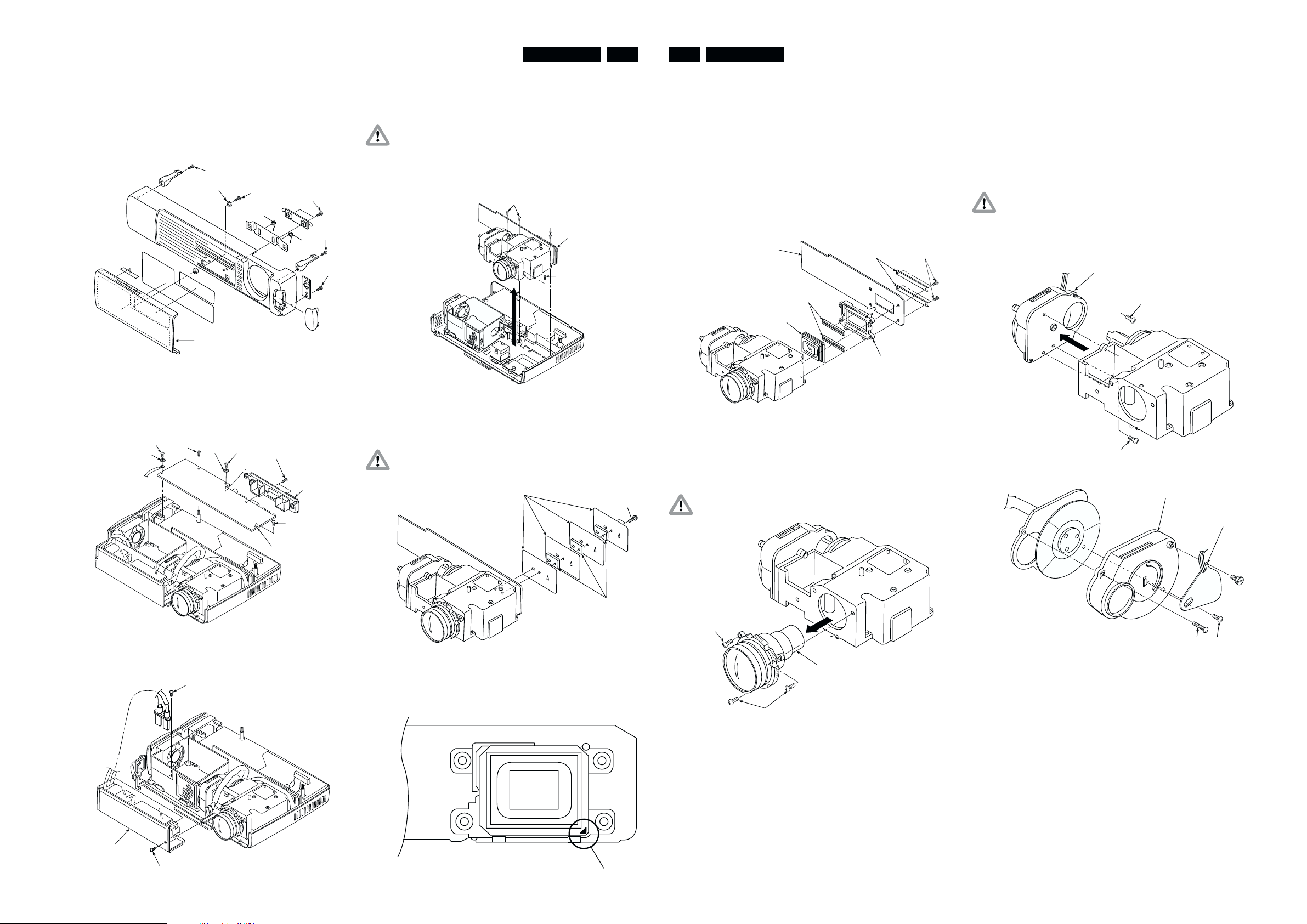
7. Lens Base Section (See Fig 7)
Remove the screws (S-7: 4 screws) as shown in Fig 7
and then remove the lens base.
Caution: Be careful when disassembling and assembling
equipment that there is no catching of wires, etc.
Do not remove the spherical mirror on the inside
of the lens base or the cylinder mirror from the
lens base as this could cause maladjustments and
shadows in the corners of the screen.
S-7
S-7
Lens
Base Section
S-7
Fig 7
8. Heat sink (See Fig 8)
Remove the screws (S-11: 2 screws) as shown in Fig 8
and then remove the heat sink.
Caution: Be careful of the attachment direction of the heat
sink
Heat sink A
S-11
10. DMD, F/M board (See Fig 10)
Remove the screws (S-9: 4 screws) shown in Fig 10
and remove these items from the lens base.
Caution: Be careful not to avoid direct finger contact with
the elastomer, the DMD surfaces and terminals or
the F/M board terminals.
Also be careful of dust or dirt adhering during
attachment.
The DMD, elastomer and F/M board have a direct
influence on the image and require special care
when handling.
F/M PWB
Elastomer
DMD
F/M Hold
Holder
Elastomer
S-9
Fig 10
11. Projection Lens (See Fig 11)
Remove the screws (S7: 3 screws) shown in Fig 11
and remove the projection lens.
Caution: When assembling be careful to avoid breaking the
spherical mirror on the inside of the lens base.
12. Color Wheel Section (See Figs 12 and 13)
Remove the screws (S-9: 3 screws) shown in Fig 12
and then remove the color wheel from the lens base.
This is a sticky connection, so pull carefully.
Remove the screws (S-4: 2 and S-14:1 screws) shown
in Fig 13 and then remove the wheel cover from the
color wheel.
Remove the wheel screw shown in Fig 13 and then
remove the wheel sensor.
Caution: Excessive tightening of screws during assembly
could cause the color wheel to contact other parts
so that it does not rotate properly. Assemble the
parts to be parrallel. When replacing the color
wheel and wheel sensor, readjustments are
required. (See page 6).
Color wheel section
S-9
S-9
Wheel cover
Fig 12
Wheel sensor
F/E board
6. Lamp Driver (See Fig 6)
Remove the screws (S-3, 17: 1 screw each) as shown in
Fig 6 and then remove the lamp driver.
S-3
Lamp
driver
S-17
Fig 5
Fig 6
9. DMD chip (See Fig 9)
Install the DMD chip so that the A portion is at the
lower right as shown in Fig 9.
Fig 9
Heat sink B
Fig 8
A
S-7
S-7
Projection Lens
Fig 11
S-14
S-4
Fig 13
PCS 106 639
PCS 106 640
Page 5

LC5131/5141 4-4 5-1 LC5131/5141
5. Block diagrams, Wiring diagram & Oscillograms
13. Light Tunnel, Aperture (See Fig 14)
Remove the screws (S-7: 3 screws) shown in Fig 14
and then remove the light tunnel from the lens base.
Remove the screws (S- : 2 screws) shown in Fig 14
and then remove the aperture from the lens base.
Caution: Do not disassemble the light tunnel.
Do not touch the glass.
S-7
Light tunnel
Aperture
S-4
S-7
Fig 14
14. Lamp House Section (See Fig 15)
Remove the screws (S-7: 3 screws) shown in Fig 15
and then remove the lamp house from the lower cover.
Remove the screw (S-15: 1 screw) shown in Fig 15
and then remove the thermistor and thermistor plate.
Remove the screw (S-7: 1 screw) shown in Fig 15 and
then remove the ballast lock base.
Removing the lamp house causes the 40 square fan
assembly to come out.
Caution: Be careful of the wiring method for the 40 square
fan. The fan passes under the lamp house from
below.
S-7
Lamp hous
S-15
40FAN(L)
S-7
Thermistor Assy
Thermistor plate
S-15
Fig 15
15. Power source section (See Fig 16)
Remove the screws (S-7: 2 screws) shown in Fig 16
and then remove the fan base from the cover.
Remove the screws (S-5, 10: 1 screw each, Spacer
D/M: 2 spacers) and then remove the power source.
Note: The power supply fan must be mounted with the wires
up. The lamp fan must be mounted with the wires
down.
S-7
S-5
Spacers D/M
Power source
40FAN DC
S-7
Fan base
Fan
gard
S-10
S-21
Fig 16
16. Front and Rear Foot, etc. (See Fig 17)
As shown in Fig 17 remove the front foot in the
following order: (1) Press the catch. (2) Push out.
S-7
Rear foot
Front foot
Lamp limit switch
2
1
Fig 17
Rotate the rear foot and remove.
Remove the screw (S-7: 1 screw) shown in Fig 17 and
remove the lamp limit switch.
5.1 Optical system principle block diagram
Description of function
1. Lamp
Light source: Flashes 300 times per second as AC
lamp.
2. RGBW color wheel
Divides light into the RGBW components using color
filters.
The W component allows a bright white to be
reproduced.
A rotation detecting sensor is used to time the lamp
which is turned OFF at the color filter seam.
The maximum speed is 7,200 rpm.
3. Condenser lens and light tunnel
Collects light divided into RGBW components by the
color filter and projects them on the effective surface of
reflection mirror 1.
Use of the light tunnel lens increases the peripheral
intensity of illumination. It reduces the difference of
brightness between the screen center and periphery,
reproduces a clear view of even the corners of the
screen.
4. Reflection mirror 1 and 2
Reflects light beamed on the mirror effective surface, to
the DMD effective surface.
5. DMD chip
Reflects the light by switching on and OFF according to
the input source at the ratio of color components for
each dot.
6. Projection lens
Enlarges and projects light from the DMD.
7. Screen
The projected light (RGBW components) forms a picture
with colors synthesized through afterglow.
PCS 106 641 PCS 106 642
Page 6

5.2 Wiring diagram
SPEAKER
PORM
POSP
PODC
PODB
POLB
POLA
POFA POFB
CN20
CN2
LAMP
DRIVER
LAMP
F/M PWB
F/E PWB
J2
CN1
WHEEL-SENSOR
DC
POWER
SUPPLY
UNIT
LAMP-SW
LAMP-FAN
DC-PSU-FAN
TEMPERATURE-SENSOR
POPA
IR-SENSOR
LC5131/5141 5-2 6-1 LC5131/5141
6. Directions for use
PCS 106 643 PCS 106 644
Page 7

LC5131/5141 6-2 6-3 LC5131/5141
PCS 106 645 PCS 106 646
Page 8

LC5131/5141 6-4 6-5 LC5131/5141
PCS 106 647 PCS 106 648
Page 9

LC5131/5141 6-6 6-7 LC5131/5141
PCS 106 649 PCS 106 650
Page 10

LC5131/5141 6-8 6-9 LC5131/5141
PCS 106 651 PCS 106 652
Page 11

LC5131/5141 6-10 6-11 LC5131/5141
PCS 106 653 PCS 106 654
Page 12

LC5131/5141 6-12 7-1 LC5131/5141
7. Alignments & Protections
8-1. Color wheel sensor adjustment
Adjustment is required in the following cases:
1. After color wheel unit replacement
2. After color wheel sensor replacement
3. After optical engine unit replacement (to be adjusted if
failure is found by inspection)
4. After F/E board replacement (to be adjusted if failure is
found by inspection)
Preparation
1. PC (Windows95/98-based computer)
2. RGB cable
3. Special-purpose software (white.exe)
4. Wrench (5 mm)
Caution: When adjusting be careful not to touch hot areas
such as the lamp. Also be careful not to short the
substrates or other parts.
8-2. Lamp replacement
Preparation
1. A cushion to prevent the main unit fro being damaged
when it is placed in a reverse position
2. A Phillips screwdriver No.1
Cautions for lamp replacement and handling
1. Before starting lamp replacement, be sure to unplug the
power supply. (Otherwise, electric shock may occur.)
2. Start lamp replacement after making sure that the lamp
is cooled.(Otherwise, fire may occur.)
3. Do not allow the lamp to be exposed to strong shock or
vibration.(Otherwise, damage or injury may occur.)
4. Do not disassemble the lamp.
Lamp replacement
1) Remove the lamp cover fastening screw.
Fig 1
Procedure
1. Make adjust when the upper and front cover has been
removed.
2. Connect between the projector and PC. (mode RGB)
3. Start the special-purpose software with the PC.
4. Press the “6" key on the keyboard. After the Figure on
the right (Fig. 1) is displayed, press the ”R" key to display
the red picture. Then check the image. Check other
than red, too (*1).
5. If there is any portion on the screen that does not turn
red, loosen the wheel screw and adjust the wheel sensor
in Fig. 2 in the vertical direction and fasten it at a position
where there is no color misalignment.
6. After adjustment, press the “Q” key on the keyboard to
terminate the software.
2) Remove the lamp cover.
3) Remove three lamp cartridge fastening screws
Note: *1. The basic black-and-white pattern s are registered
PCS 106 655 PCS 106 656
Fig 2
on the number keys (0-9), and colors can be
changed with the following letter keys:
W (white), K (black), R (red), G (green), B (blue),
M (magenta) and C (cyan)
Page 13

LC5131/5141 7-2 7-3 LC5131/5141
4) Hold the handle and take out the lamp housing.
5) Install a new lamp housing.
8) Reset the lamp time.
After the Information Menu appears, select “Reset Lamp
Time” and press the ENTER button.
To reset, press the ENTER button. To quit, press the
CANCEL button
9) When power cuts off after lamp was used over 1100 hours
After replacing the lamp housing, connect the power cord
and set in standby. Hold down the unit SOURCE and
AUTO buttons simultaneously for at least 5 seconds.
8.3. Protections
8.3-1. Internal Temperature Detection
There is a thermostat in the lamp housing, which switches off
the lamp when thermostat temperature has reached 90°C or
more.
The power supply, like the lamp driver, has a thermostat.
These two thermostats switch the power off at respective
temperatures of 120 and 115 degrees Centigrade or higher.
Status Meaning Solution
OFF (lamp off) Normal
ON (lamp on)
Flashing at intervals of one second
(ON for 0.5 sec./OFF for 0.5 sec.)
Flashing at intervals of 4 seconds
(ON for 2 sec./OFF for 2 sec.)
The lamp has been used in excess of 1,000
hours
The lamp is not installed correctly. Install the lamp correctly
The temperature protector has been triggered
Power may not be turned on if you switch ON
the main power switch immediately after the
temperature protector has been triggered and
the main power switch has been
turned OFF.
The lamp lighting voltage failure detection
protector has been triggered.
Replace with a new lamp and reset the lamp
usage time
If the room temperature is high, move the
projector to a cooler location.
If the temperature inside the projector is high,
check the cooling fan vents and bottom vents,
and clean and remove any substance with which
these vents are clogged.
Wait for one minute; then turn ON the switch.
Wait for one minute; then turn ON power.
6) Fasten three lamp housing fastening screws.
7) Install the lamp cover and fasten it with fastening screws
8.3-2. Lamp Unit and Interlock Switch
If the lamp cover is not mounted, the lamp does not turn on
even if it is provided.
8.3-3. Status LED Specifications
The Status LED lamp flashes if the lamp is not turned on.
The flashing cycle allows you to trace the cause of the
trouble. (See the drawing on the right and Table below.)
Flashing at intervals of 8 seconds
(ON for 4 sec./OFF for 4 sec.)
Flashing at intervals of 12 seconds
(ON for 6 sec./OFF for 6 sec.)
The fan is stopped Inspect the exhaust fan
Wait for one minute; then turn it ON. If this does
The lamp fails to light up
not solve the problem, check
the inside.
PCS 106 657 PCS 106 658
Page 14

8. Parts list
LC5131/5141 8-1 8-2 LC5131/5141
Upper Cover Section
1 Upper cover assy 9965 000 07243
2 Upper cover no spare part
3 Button op no spare part
4 Led lens no spare part
5 Foot button no spare part
6 Foot button spring no spare part
7 Sensor cover r no spare part
8 Upper plate no spare part
9 Upper tape s no spare part
10 Upper tape b no spare part
11 Insulate tape no spare part
12 Plate spacer no spare part
13 Urethane form l no spare part
14 Upper cover mesh no spare part
15 Insulate sheet f/e no spare part
16 U3 gasket no spare part
17 Speaker assy 9965 000 07137
18 Front panel 9965 000 07138
19 Slider plate 9965 000 07296
20 Slider spring 1 9965 000 07297
21 Slider spring 2 9965 000 07298
22 Slider roller 9965 000 07299
23 Push slider 9965 000 07300
24 IR pwb 9965 000 07170
25 IR cable assy 9965 000 07301
26 Front hook 1 9965 000 07171
27 Front hook 2 9965 000 07172
28 Front door assy (no 29-32) 9965 000 07244
29 Front door no spare part
30 Front door sheet 1 no spare part
31 Front door sheet 2 no spare part
32 Front door sheet 3 no spare part
33 Louver screw 9965 000 07302
34 Spacer d/m 9965 000 07305
PCS 106 659
pwb section
35 F/E PWB LC5131 9965 000 07139
35 F/E PWB LC5141 9965 000 07186
36 Connector panel 9965 000 07140
37 Connector sheet 9965 000 07141
38 Spacer rgb 9965 000 07306
39 Lens base urethane form 9965 000 07307
40 Lamp driver stud 9965 000 07173
41 Limit sw board 9965 000 07142
42 Lamp driver 9965 000 07143
43 Insulate sheet l/d 9965 000 07308
44 Radiation sheet l/d 9965 000 07309
45 Lamp driver lock base 9965 000 07174
46 Louver panel 9965 000 07144
47 Lamp house assy (no 48-52) 9965 000 07145
48 Lamp house no spare part
49 Lamp house mesh no spare part
PCS 106 660
50 Lamp house guard no spare part
51 Lamp house sheet no spare part
52 Lamp house mesh tape no spare part
53 Thermister plate 9965 000 07310
54 Thermister assy 9965 000 07146
55 40fan assy T-20H 9965 000 07147
56 40fan assy DC 9965 000 07148
57 Fan cushion 9965 000 07311
58 Fan vibration proof rubber 9965 000 07312
59 Fan guard 9965 000 07313
60 Fan base 9965 000 07175
61 Core 9965 000 07314
62 Fan fence 9965 000 07315
63 Gnd cable 9965 000 07316
134 Lamp sync cable assy 9965 000 07433
Page 15

LC5131/5141 8-3 8-4 LC5131/5141
Lower Cover Section
64 Lower cover 9965 000 07149
65 Inlet spacer 9965 000 07317
66 Spacer D/M 9965 000 07305
67 DC psu 9965 000 07150
68 Insulate sheet DC-1 9965 000 07318
69 Insulate sheet DC-2 9965 000 07319
70 Rear foot 9965 000 07151
71 Rear foot rubber 9965 000 07152
72 front foot 9965 000 07153
73 Lamp cover assy (no 74-77) 9965 000 07278
74 Lamp cover no spare part
75 Lamp cover screw no spare part
76 Lamp cover screw sp no spare part
77 Lamp cover guard no spare part
78 lamp 8670 931 13009
PCS 106 661 PCS 106 662
Optical Section
79 Lens base assy 9965 000 07154
80 Lens base no spare part
81 Spherical mirror assy no spare part
82 Cylinder mirror asy no spare part
83 Aparture no spare part
84 Lens base cover no spare part
85 Lens base sheet no spare part
86 Insulate sheet l/b 9965 000 07320
87 Lens unit 9965 000 07155
88 Condenser lens assy 9965 000 07156
89 Color wheel 9965 000 07154
90 Wheel cover 9965 000 07176
91 Rubber sheet 9965 000 07177
92 Wheel sensor board assy 9965 000 07157
93 Wheel screw 9965 000 07321
94 Sticker sd-10 9965 000 07322
95 Dmd set LC5131 9965 000 07158
95 Dmd set LC5141 9965 000 07187
96 push F/M PWB 9965 000 07323
97 Heat sink A 9965 000 07324
98 Heat sink B 9965 000 07325
Page 16

LC5131/5141 8-5 8-6 LC5131/5141
Label Section
99 Rating Label LC5131 9965 000 07326
99 Rating Label LC5141 9965 000 07332
100 Caution seal a(hot) 9965 000 07327
101 Caution seal c(lens) 9965 000 07328
102 Lamp caution seal a no spare part
103 FCC label 9965 000 07329
104 Logo mark 9965 000 07185
105 Pop label LC5131 no spare part
105 Pop label LC5141 no spare part
Accessories Section
106 Out carton no spare part
107 Carton box 9965 000 07178
108 Packing 9965 000 07179
109 Bag(machine) 9965 000 07180
110 Accessory box 9965 000 07181
111 Bag(manual,accessory) 9965 000 07182
112 Operation manual 9965 000 07160
113 Quick start guide no spare part
114 Inlay sheet no spare part
115 Warranty card no spare part
116 Warranty card envelope USA no spare part
117 Warranty card envelope EU no spare part
118 Carrying case 9965 000 07183
119 Accessory pad 9965 000 07330
PCS 106 663 PCS 106 664
120 Cable case 9965 000 07184
121 Remote controller 9965 000 07159
122 Remote controller label 9965 000 07331
123 AAA battery no spare part
124 Power cable (1.8m) ul 9965 000 07161
125 Power cable (1.8m) cee 9965 000 07162
126 Video cable(1p 1m) 9965 000 07163
127 Audio adapter 9965 000 07164
128 s-video cable(1m) 9965 000 07165
129 RGB cable (1m) 9965 000 07166
130 Mini jack cable(1m) 9965 000 07167
131 ps/2 mouse cable 9965 000 07168
132 USB mouse cable 9965 000 07169
133 Desiccant(30g) no spare part
 Loading...