

Page 1
Colour Television Chassis
LC1.15E
AA
Contents Page
Safety Precautions 2
Servicing Precautions 3
Description of Controls 5
Troubleshooting 8
Wiring Diagram 9
Block Diagram 10
Main Board for LC151x01-A3 LCD Panel 11
Main Board PWB for LC151x01-A3 LCD Panel 12-13
Control and Tuner Panel PWB 14
Main Board for LC151x01-C3P1 LCD Panel 15
Main Board PWB for LC151x01-C3P1 LCD P. 16-17
Control and Tuner Panel PWB 18
Adjustment Instruction 19
Exploded View 21
Spare Parts List 22
Revision List 24
©
Copyright 2003 Philips Consumer Electronics B.V. Eindhoven, The Netherlands.
All rights reserved. No part of this publication may be reproduced, stored in a
retrieval system or transmitted, in any form or by any means, electronic,
mechanical, photocopying, or otherwise without the prior permission of Philips.
Published by LM 0367 Printed in the Netherlands Subject to modification EN 3122 785 12511
Page 2
SAFETY PRECAUTIONS
Many electrical and mechanical parts in this chassis have special safety-related characteristics. These parts are identified by in
the Schematic Diagram and Replacement Parts List.
It is essential that these special safety parts should be replaced with the same components as recommended in this manual to
prevent X-RADIATION, Shock, Fire, or other Hazards.
Do not modify the original design without permission of manufacturer.
General Guidance
An lsolation Transformer should always be used during
the servicing of a receiver whose chassis is not isolated from
the AC power line. Use a transformer of adequate power rating
as this protects the technician from accidents resulting in
personal injury from electrical shocks.
It will also protect the receiver and it's components from being
damaged by accidental shorts of the circuitary that may be
inadvertently introduced during the service operation.
If any fuse (or Fusible Resistor) in this TV receiver is blown,
replace it with the specified.
When replacing a high wattage resistor (Oxide Metal Film
Resistor, over 1W), keep the resistor 10mm away from PCB.
Keep wires away from high voltage or high temperature parts.
Due to high vacuum and large surface area of picture tube,
extreme care should be used in handling the Picture Tube.
Do not lift the Picture tube by it's Neck.
X-RAY Radiation
Warning:
To determine the presence of high voltage, use an accurate
high impedance HV meter.
Adjust brightness, color, contrast controls to minimum.
Measure the high voltage.
The meter reading should indicate
23.5
!1.5KV: 14-19 inch, 26!1.5KV: 19-21 inch,
29.0
!1.5KV: 25-29 inch, 30.0 ! 1.5KV: 32 inch
If the meter indication is out of tolerance, immediate service
and correction is required to prevent the possibility of
premature component failure.
Before returning the receiver to the customer,
always perform an AC leakage current check on the exposed
metallic parts of the cabinet, such as antennas, terminals, etc.,
to be sure the set is safe to operate without damage of
electrical shock.
Leakage Current Cold Check(Antenna Cold Check)
With the instrument AC plug removed from AC source,
connect an electrical jumper across the two AC plug prongs.
Place the AC switch in the on positioin, connect one lead of
ohm-meter to the AC plug prongs tied together and touch other
ohm-meter lead in turn to each exposed metallic parts such as
antenna terminals, phone jacks, etc.
If the exposed metallic part has a return path to the chassis, the
measured resistance should be between 1MΩ and 5.2MΩ.
When the exposed metal has no return path to the chassis the
reading must be infinite.
An other abnormality exists that must be corrected before the
receiver is returned to the customer.
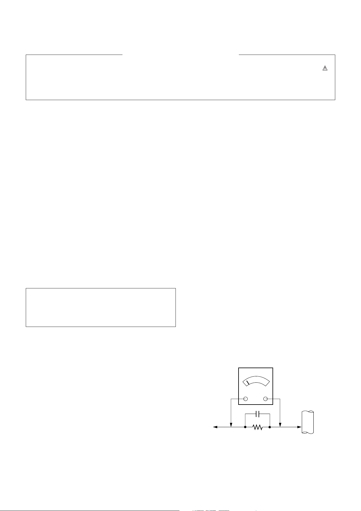
Leakage Current Hot Check (See below Figure)
Plug the AC cord directly into the AC outlet.
Do not use a line Isolation Transformer during this check.
Connect 1.5K/10watt resistor in parallel with a 0.15uF capacitor
between a known good earth ground (Water Pipe, Conduit, etc.)
and the exposed metallic parts.
Measure the AC voltage across the resistor using AC
voltmeter with 1000 ohms/volt or more sensitivity.
Reverse plug the AC cord into the AC outlet and repeat AC
voltage measurements for each esposed metallic part. Any
voltage measured must not exceed 0.75 volt RMS which is
corresponds to 0.5mA.
In case any measurement is out of the limits sepcified, there is
possibility of shock hazard and the set must be checked and
repaired before it is returned to the customer.
Leakage Current Hot Check circuit
The source of X-RAY RADIATION in this TV receiver is the
High Voltage Section and the Picture Tube.
For continued X-RAY RADIATION protection, the
replacement tube must be the same type tube as specified in
the Replacement Parts List.
1.5 Kohm/10W
To Instrument's
exposed
METALLIC PARTS
Good Earth Ground
such as WATER PIPE,
CONDUIT etc.
AC Volt-meter
IMPORTANT SAFETY NOTICE
0.15uF
Page 3

CAUTION: Before servicing receivers covered by this service
manual and its supplements and addenda, read and follow the
SAFETY PRECAUTIONS
on page 3 of this publication.
NOTE:
If unforeseen circumstances create conflict between the
following servicing precautions and any of the safety
precautions on page 3 of this publication, always follow the
safety precautions. Remember: Safety First.
General Servicing Precautions
1. Always unplug the receiver AC power cord from the AC
power source before;
a. Removing or reinstalling any component, circuit board
module or any other receiver assembly.
b. Disconnecting or reconnecting any receiver electrical plug
or other electrical connection.
c.
Connecting a test substitute in parallel with an electrolytic
capacitor in the receiver.
CAUTION: A wrong part substitution or incorrect
polarity installation of electrolytic capacitors may result
in an explosion hazard.
d. Discharging the picture tube anode.
2. Test high voltage only by measuring it with an appropriate
high voltage meter or other voltage measuring device (DVM,
FETVOM, etc) equipped with a suitable high voltage probe.
Do not test high voltage by "drawing an arc".
3. Discharge the picture tube anode only by (a) first connecting
one end of an insulated clip lead to the degaussing or kine
aquadag grounding system shield at the point where the
picture tube socket ground lead is connected, and then (b)
touch the other end of the insulated clip lead to the picture
tube anode button, using an insulating handle to avoid
personal contact with high voltage.
4. Do not spray chemicals on or near this receiver or any of its
assemblies.
5. Unless specified otherwise in this service manual, clean
electrical contacts only by applying the following mixture to
the contacts with a pipe cleaner, cotton-tipped stick or
comparable nonabrasive applicator; 10% (by volume)
Acetone and 90% (by volume) isopropyl alcohol (90%-99%
strength)
CAUTION: This is a flammable mixture.
Unless specified otherwise in this service manual, lubrication
of contacts in not required.
6. Do not defeat any plug/socket B+ voltage interlocks with
which receivers covered by this service manual might be
equipped.
7. Do not apply AC power to this instrument and/or any of its
electrical assemblies unless all solid-state device heat sinks
are correctly installed.
8. Always connect the test receiver ground lead to the
receiver chassis ground before connecting the test receiver
positive lead.
Always remove the test receiver ground lead last.
9.
Use with this receiver only the test fixtures specified in this
service manual.
CAUTION: Do not connect the test fixture ground strap to
any heatsink in this receiver.
Electrostatically Sensitive (ES) Devices
Some semiconductor (solid state) devices can be damaged
easily by static electricity. Such components commonly are
called
Electrostatically Sensitive (ES) Devices.
Examples of
typical ES devices are integrated circuits and some fieldeffect
transistors and semicounductor "chip" components. The
following techniques should be used to help reduce the
incidence of component damage caused by static by static
electricity.
1. Immediately before handling any semiconductor component
or semiconductor-equipped assembly, drain off any
electostatic charge on your body by touching a known earth
ground. Alternatively, obtain and wear a commercially
available discharging wrist strap device, which should be
removed to prevent potential shock reasons prior to
applying power to the unit under test.
2. After removing an electrical assembly equipped with ES
devices, place the assembly on a conductive surface such as
aluminum foil, to prevent electrostatic charge buildup or
exposure of the assembly.
3. Use only a grounded-tip soldering iron to solder or unsolder
ES devices.
4. Use only an anti-static type solder removal device. Some
solder removal devices not classified as "anti-static" can
generate electrical charges sufficent to demage ES devices.
5. Do not use freon-propelled chemicals. These can generate
electrical charges sufficient to damage ES devices.
6. Do not remove a repalcement ES device from its protective
package until immediately before you are ready to install it.
(Most replacement ES devices are packaged with leads
electrically shorted together by conductive foam, aluminum
foil or comparable conductive material).
7. Immediately before removing the protective material from
the ieads of a replacement ES device, touch the protective
material to the chassis or circuit assembly into which the
device will be installed.
CAUTION:Be sure no power is applied to the chassis or
circuit, and observe all other safety precautions.
8. Minimize bodily motions when handling unpackaged
replacement ES devices. (Otherwise harmless motion such
as the bruching together of your clothes fabric or the lifting
of your foot from a carpeted floor can generate static
electricity sufficient to damage an ES device.)
General Soldering Guidelines
1. Use a grounded-tip, low-wattage soldering iron and
appropriate tip size and shape that will maintan tip
temperature within the range or 500
cF to 600cF.
2. Use an appropriate gauge of RMA resin-core solder
composed of 60 parts tin/40 parts lead.
3. Keep the soldering iron tip clean and well tinned.
4. Thorohly clean the surfaces to be soldered. Use a mall
wirebristle (0.5 inch, or 1.25cm) brush with a metal handle.
Do not use freon-propelled spray-on cleaners.
5. Use the following unsoldering technique
a. Allow the soldering iron tip to reach normal temperature.
(500cF to 600cF)
b. Heat the component lead until the solder melts.
c. Quickly draw the melted solder with an anti-static,
suction-type solder removal device or with solder braid.
CAUTION: Work quickly to avoid overheating the
circuiboard printed foil.
6. Use the following soldering technique.
a. Allow the soldering iron tip to reach a normal
temperature (500cF to 600cF)
b. First, hold the soldering iron tip and solder the strand
against the component lead until the solder melts.
SERVICING PRECAUTIONS
Page 4

c. Qulckly move the soldering iron tip to the junction of the
component lead and the printed circuit foil, and hold it
there only until the solder flows onto and around both the
component lead and the foil.
CAUTION: Work quickly to avoid overheating the circuit
board printed foil.
d. Closely inspect the solder area and remove any excess
or splashed solder with a small wire-bristle brush.
IC Remove/Replacement
Some chassis circuit boards have slotted holes (oblong) through
which the IC leads are inserted and then bent flat against the
circuit foil. When holes are the slotted type, the following
technique should be used to remove and replace the IC. When
working with boards using the familiar round hole, use the
standard technique as outlined in parapraphs 5 and 6 above.
Removal
1. Desolder and straighten each IC lead in one operation by
gently prying up on the lead with the soldering iron tip as the
solder melts.
2. Draw away the melted solder with an anti-static suctiontype solder removal device (or with solder braid) before
removing the IC.
Replacement
1. Carefully insert the replacement IC in the circuit boare.
2. Carefully bend each IC lead against the circuit foil pad and
solder it.
3. Clean the soldered areas with a small wire-bristle brush.
(It is not necessary to reapply acrylic coating to the areas).
"Small-Signal" Discrete Transistor
Removal/Replacement
1. Remove the defective transistor by clipping its leads as
close as possible to the component body.
2. Bend into a "U" shape the end of each of three leads
remaining on the circuit board.
3. Bend into a "U" shape the replacement transistor leads.
4. Connect the replacement transistor leads to the
corresponding leads extending from the circuit board and
crimp the "U" with long nose pliers to insure metal to metal
contact then solder each connection.
Power Output, Transistor Device
Removal/Replacement
1. Heat and remove all solder from around the transistor leads.
2. Remove the heatsink mounting screw (if so equipped).
3. Carefully remove the transistor from the heat sink of the
circuit board.
4. Insert new transistor in the circuit board.
5. Solder each transistor lead, and clip off excess lead.
6. Replace heatsink.
Diode Removal/Replacement
1. Remove defective diode by clipping its leads as close as
possible to diode body.
2. Bend the two remaining leads perpendicula y to the circuit
board.
3. Observing diode polarity, wrap each lead of the new diode
around the corresponding lead on the circuit board.
4. Securely crimp each connection and solder it.
5. Inspect (on the circuit board copper side) the solder joints of
the two "original" leads. If they are not shiny, reheat them
and if necessary, apply additional solder.
Fuse and Conventional Resistor
Removal/Replacement
1. Clip each fuse or resistor lead at top of the circuit board
hollow stake.
2. Securely crimp the leads of replacement component around
notch at stake top.
3. Solder the connections.
CAUTION: Maintain original spacing between the replaced
component and adjacent components and the circuit board
to prevent excessive component temperatures.
Circuit Board Foil Repair
Excessive heat applied to the copper foil of any printed circuit
board will weaken the adhesive that bonds the foil to the circuit
board causing the foil to separate from or "lift-off" the board.
The following guidelines and procedures should be followed
whenever this condition is encountered.
At IC Connections
To repair a defective copper pattern at IC connections use the
following procedure to install a jumper wire on the copper
pattern side of the circuit board. (Use this technique only on IC
connections).
1. Carefully remove the damaged copper pattern with a sharp
knife. (Remove only as much copper as absolutely
necessary).
2. carefully scratch away the solder resist and acrylic coating
(if used) from the end of the remaining copper pattern.
3. Bend a small "U" in one end of a small gauge jumper wire and
carefully crimp it around the IC pin. Solder the IC connection.
4. Route the jumper wire along the path of the out-away
copper pattern and let it overlap the previously scraped end
of the good copper pattern. Solder the overlapped area and
clip off any excess jumper wire.
At Other Connections
Use the following technique to repair the defective copper
pattern at connections other than IC Pins. This technique
involoves the installation of a jumper wire on the component
side of the circuit board.
1. Remove the defective copper pattern with a sharp knife.
Remove at least 1/4 inch of copper, to ensure that a
hazardous condition will not exist if the jumper wire opens.
2. Trace along the copper pattern from both sides of the
pattern break and locate the nearest component that is
directly connected to the affected copper pattern.
3. Connect insulated 20-gauge jumper wire from the lead of
the nearest component on one side of the pattern break to
the lead of the nearest component on the other side.
Carefully crimp and solder the connections.
CAUTION: Be sure the insulated jumper wire is dressed so
the it does not touch components or sharp edges.
Page 5

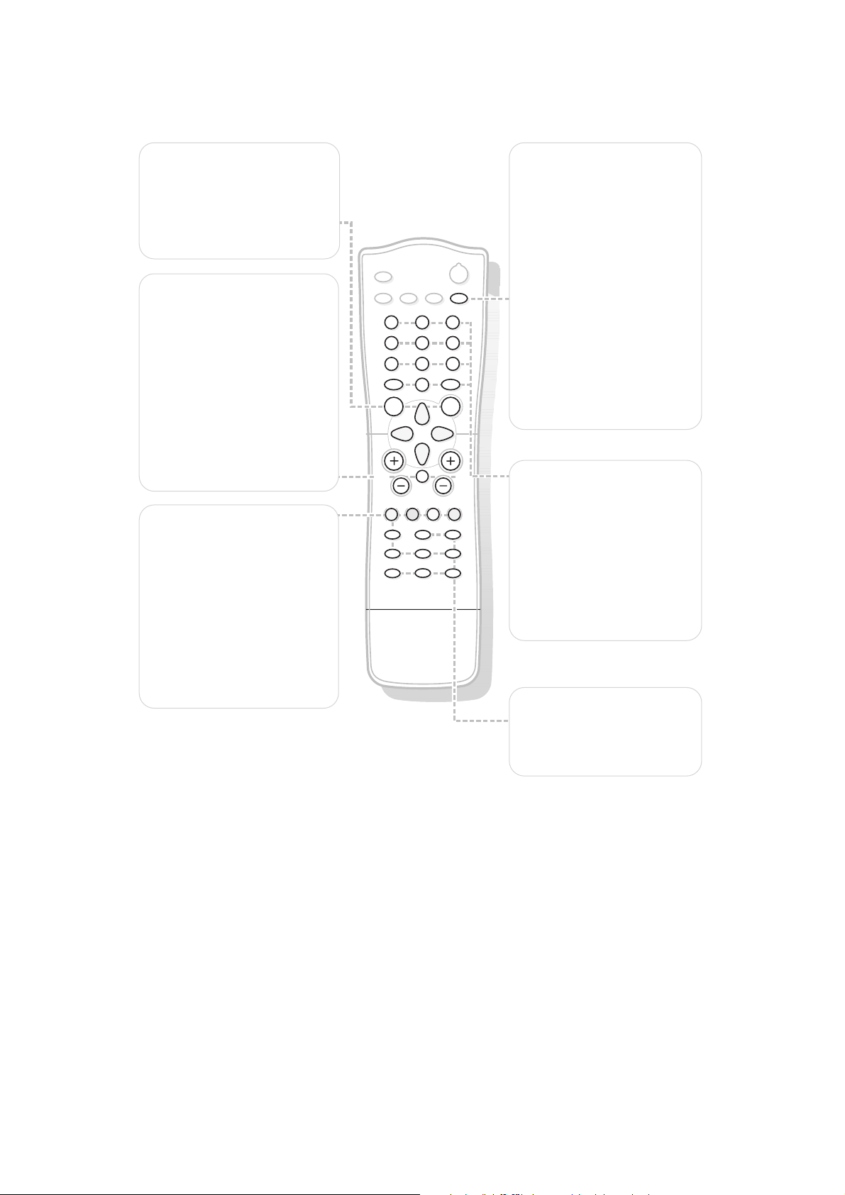
DESCRIPTION OF CONTROLS
MENU
OK
PV
¬
5
1
3
2
4
6
7
9
8
0
0
LIST
h
f g
Ò
‡
π
c
b
®
†
U
e
k
C
a
D
B
M
AUTO
AUTO
w
Y-Z
w Source
Select your computer or other
peripherals:press repeatedly to
select
TV, AV1, AV2,S-VIDEO
or PC monitor mode.
X Bilingual choice and
sound mode selection
Press this key
• to switch from
Stereo to
Mono sound in case of
stereo transmission,or from
Nicam Stereo to Nicam
Mono
,in case of digital
transmission
• to switch from
Nicam Dual
Y to Nicam Dual Z or
Nicam Dual X in case of
Nicam Dual transmission
• to choose between
Dual Y,
Dual Z or Dual X in case
of bilingual transmission:
Dual Y sends the primary
broadcast language to the
loudspeakers;
Dual Z sends the secondary
broadcast language to the
loudspeakers;
Dual X sends a separate
language to each loudspeaker.
Note: in case of weak stereo
sound signals, with stereo or
Nicam stereo transmission,select
mono reception.
Sound output selection in AV mode
In AV mode, you can select the output sound for the left and right loudspeakers.
Press the X key repeatedly to select:
• L+R:the audio signal from the audio L input is sent to the left loudspeaker, the audio signal
from the audio R input to the right loudspeaker
• L+L:the audio signal from the audio L input is sent to the left and right loudspeakers
• R+R:the audio signal from the audio R input is sent to the left and right loudspeakers.
B Standby
Switches the TV on from
standby or off to standby.
AUTO keys
To select predefined picture
and sound settings.
a
AUTO picture
Each time it is pressed,a
different picture setting is
selected,corresponding with
specific factory settings of
Contrast,Brightness, Colour
and Sharpness.
M
AUTO sound
Each time it is pressed,a
different sound setting is
selected,corresponding with
specific factory settings of
treble and bass.
Personal refers to the personal
preference settings of picture
and sound selected and stored
in the picture and sound menu.
Page 6
B
M
a
AUTO
AUTO
w
Y-Z
C
h
f g
c
b
e
k
Ò
‡
π
®
†
U
D
1
2
9
3
6
5
7
4
8
0
0
LIST
MENU
OK
P
¬
V
V Volume
Press + or - to adjust the
volume.
¬ Mute
Temporarily interrupt the
sound or restore it.
P Programme selection
• to browse through the TV
channels which are not
skipped
• to switch the TV on from
standby.
®Ò‡π† Video
recorder keys
U Time display
The time, downloaded from the
TV channel (with teletext
broadcast) stored on
programme number 1 or the
lowest not skipped programme
number, is displayed on the
screen.
0/9 Digit keys
To select a TV channel.
0 Previous programme
To display the previously
selected TV channel.
LIST Programme list
To display the programme list.
b Teletext on/off
Teletext functions
hUfgcek
D Sleeptimer
With this key you can set a
time period after which the
TV should switch itself to
standby.
Press the key repeatedly to
select the number of minutes.
The counter runs from B 0,
10,20, 30... to 240 minutes.
The timer begins to count
down from the number of
minutes selected.
Note:To view the remaining time,
press the
D key once.To cancel
the sleep time, repeatedly press
the
D key until B 0 appears.
MENU Press repeatedly to
display each menu.
OK Press this key to activate
your choice,when in the menus.
Page 7
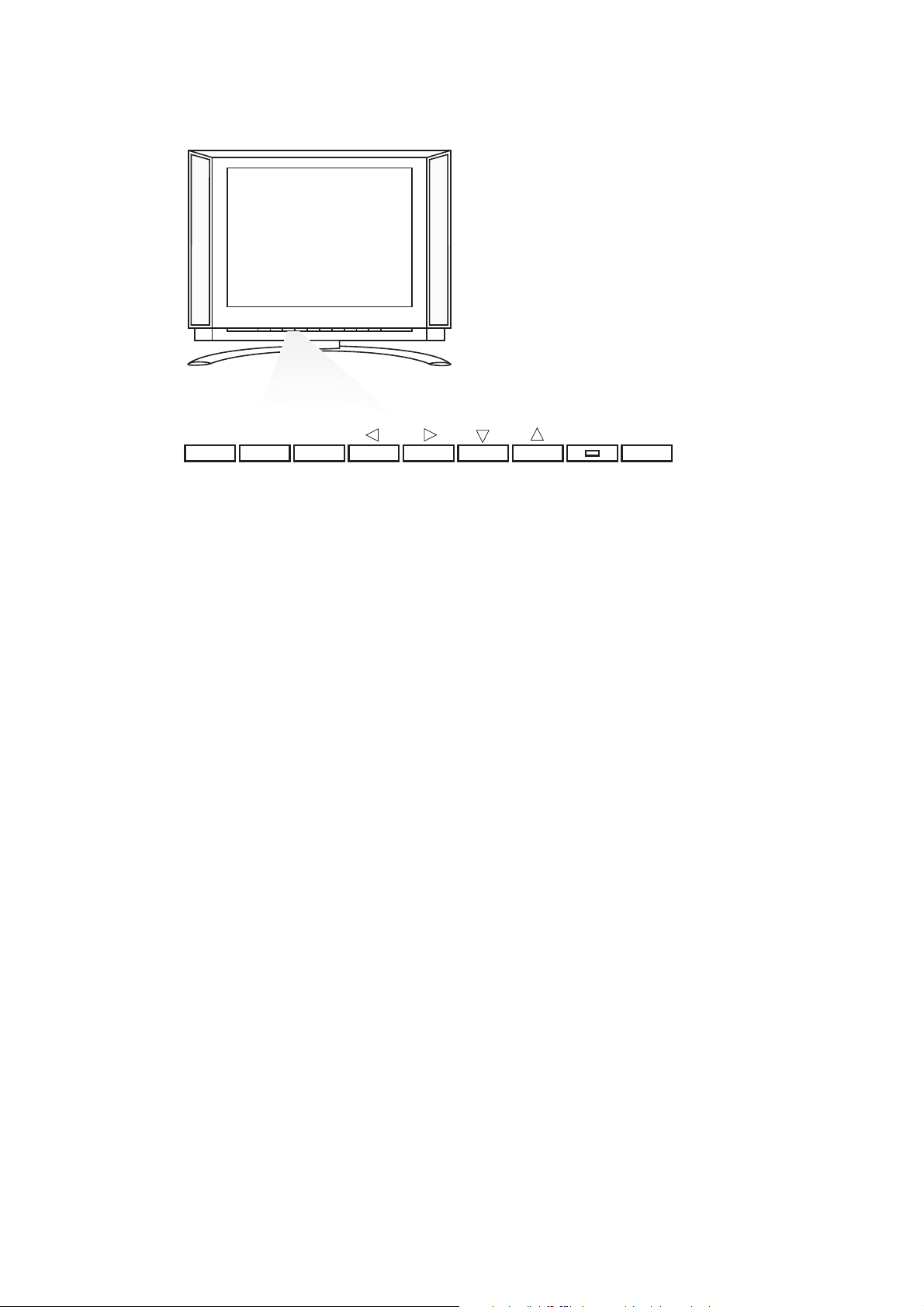
Should your remote control be lost or broken you can still operate your TV with the keys
in front of the TV.
ON/OFF:Press the power ON/OFF key to switch the TV on or off
TV/VIDEO:Press repeatedly to select TV,AV or PC monitor mode
MENU:Press repeatedly to display each menu
OK: - Press this key to activate your choice when in the menu
-
Auto demonstration:Keep the OK key pressed for about 10 seconds.
All the menus are being displayed automatically one after the other.
To stop Auto demonstration, press any key on the front panel.
- VOL + : - Press - or + to select a menu item;
- Press - or + to adjust the volume;
- Press - or + to adjust the menu settings.
- CH/PR +:- Press - or + to browse through the TV channels which are not skipped;
- Press - or + to select a menu item;
- To switch the TV on from standby.
B: Switches the TV on from standby or off to standby.
The B indicator lights up brightly when the TV is in standby,dims when the TV is
switched on.
TV / VIDEO MENU
OK
_
VOL
+
_
CH / PR
+
B
ON / OFF
Page 8
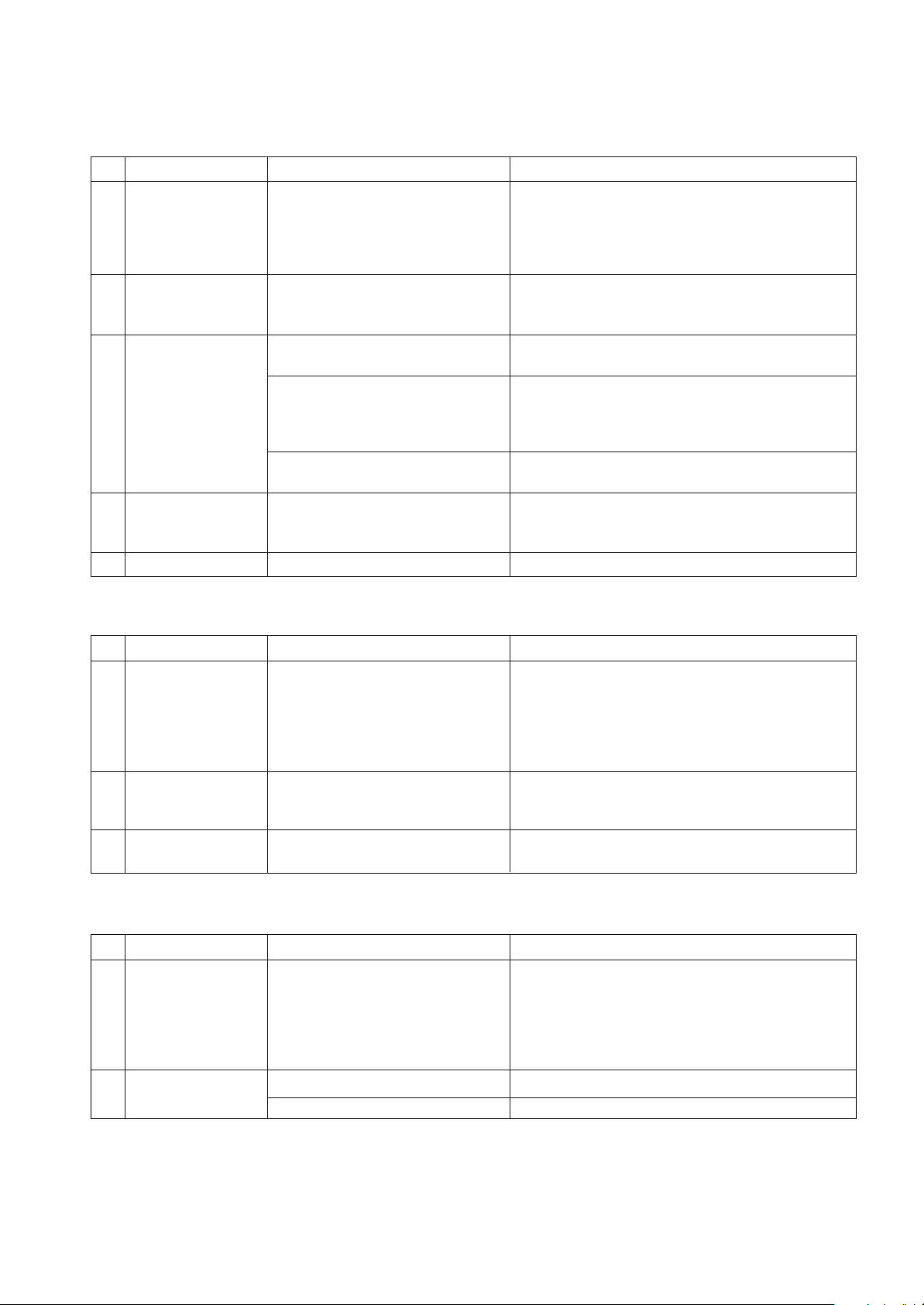
9 No sound Defective Reset IC of IC603 1) Check volume and speaker
- Speaker Defective MSP3400D of IC601 - Sound comes out only when being inputted into Audio
- Earphone Defective B+(8V,5V) of IC604,605. L/R
2) Check after replacing IC603
3) Replace IC601
4) Check and replace B+ of IC604,605.
10 Video color beat noise Earphone shield case being touched
Check the mould of shield and JA401, Replace shield case
Soldering IC301 and IC507 Re-soldering
1 Soft touch doesn’t Defective speaker wire 1) Make some space between the speaker wire and
function properly and inverter wire the Soft touch Board by sticking the speaker wire
to the guide hole of the cabinet.
2) Arrange working state of A1. Tape in the inverter wire
and correct working state of the Shield case.
2 Soft touch doesn’t 1) Broken components and 1) Check Soft touch with eyes
function soldering of them Check and repair soldering
2) P101 connector error 2) Check and repair the P101 connector
3 No screen Input error of inverter connector 1) Bend the pin legs of P801 connector -> recheck them
2) Check and repair the IC801,802 SI4925
P502 and Pin 21 connector 1) Check and fix P502 connector
being slipped out 2) Check and fix the components at P502 LCD module
and at main board.
3) Check Pin21.
Cracked components and 1) Check and repair tuner board and main board
soldering at tuner board 2) Solder Q403, Q402 and C153
4 Dark screen 1) Defective LCD lamp 1) Replace the inverter
2) Defective inverter 2) Replace the LCD lamp
3) Input error of inverter connector 2) Check the connector input.
5 Broken OSD display Defective the font rom of IC501 Check and replace the font rom of IC501
TROUBLESHOOTING
1. General Features
2. PC Mode
No. Symptom Cause Check Point
No. Symptom Cause Check Point
Check Point
6 Screen noise Clock or phase being 1) Resettig is needed according to the video card of each
not able to be adjusted PC
2) Horizontal noise : adjust phase until no horizontal
noise occurres
3) Vertical noise : adjust clock in menu until no vertical
noise occurres
7 Screen position error Screen position error 1) Play the Auto Configure in Menu.
horizontally or vertically 2) Adjust horizontal and vertical position until the screen
displayes normally
8 Color beat noise Soldering AD converter Recheck adn repair AD9884
or making it short
3. TV and external input
No. Symptom Cause
Page 9

To Lamp
9965 000 20401 (A3 Panel)
9965 000 20402 (C3 Panel)
To Control PWB
P401
To Lamp
RE/RL-15LA40 Wiring Diagram (15.1”)
P801
Tuner
P601
P602
6631V25016G (3P)
6631V25016P (4P)
To Speaker
P502
9965 000 20403 (A3 Panel)
9965 000 20404 (C3 Panel)
To Panel
Page 10

Tuner & IF
- TAUC-S120D
- TAFC-M130D
- TAFC-Z140D
Audio
Processor
- MSP3410D
Ext- L
Micro-Controller
- INFINEON ( SDA55XX )
L
LCD
< LCD TV System Block Diagram >
Video
Decorder
- VPC3230D
Video Scaler
- MX88L284
Computer
Signal
- D-Sub
R/G/B
H/V
D-R/G/B,
H / V -Sync,
Den, Clock
From
Computer
OSD -IC
MC141585
CVBS
Audio-Amp
LA4282
R
Ext- R
SIF
For MNT Application
LM151X3 - 8-bits
1H/1V
A to D Converter
- AD9884
For PC Input
- Contrast
- Brightness
- Color
Ext_Video
Ext_Y/C
OSD B/R/G/B
Scart RGB
For TV
. Contrast
. Brightness
. Color
. Tint
CVBS For TXT
AM
Interface
- TMDS (8bits)21 pin
RGB Switching
TDA8601
Y / Cb / Cr
RGB in
Back Light
Inverter Assy
CVBS OUT
Page 11

Service Sheet of MF-004A
P/N : 3854VA0077A-S
DATE : 2000.10.02
Main Board for LC151X01-A3 LCD Panel
Page 12

Main Board for LC151X01-A3 LCD Panel (Top Side)
Page 13

Main Board for LC151X01-A3 LCD Panel (Bottom Side)
Page 14

CONTROL
TUNER(TOP)
TUNER(BOTTOM)
Page 15

Main Board for LC151X01-C3P1 LCD Panel
Page 16

Main Board for LC151X01-C3P1 LCD Panel (Top Side)
Page 17

Main Board for LC151X01-C3P1 LCD Panel (Bottom Side)
Page 18

CONTROL
TUNER(TOP)
TUNER(BOTTOM)
Page 19

- 9 -
1. Application Object
This instruction is for the application to the LCD TV.
2. Notes
(1) This set uses an adapter, so connect the adapter and the
set correctly before adjustment.
(2) The adjustment must be performed under the correct
sequence.
(3) The adjustment must be performed in the circumstance of
25
! 5cC of temperature and 65±10% of relative humidity if
there is no specific designation.
(4) The input voltage of the receiver must keep 220V, 60Hz in
adjusting.
(5) The set must be operated for 30 minutes preliminarily
before adjustment if there is no specific designation.
[ Ô Heat RunÕ must be performed with the full white signal or TV
noise signal in the internal part of the set.
[ The time for Ô Heat RunÕ can be changed owing to production
plan.
3. PC Input Mode Adjustment
3-1. Required Test Equipment
(1) A pattern generator being in proportion to VG819 ; Pattern
of 64 tones
(2) A remote control
3-2. Preparation for Adjustment
(1) Perform Ô Heat RunÕ for more than 30 minutes in white
pattern.
(2) Connect the signal of pattern generator with LCD TV.
(3) Lean the set 45¡ backward. (Adjustment is easy.)
(4) Set the PC mode menu as below.
3-3. White Adjustment
(1) Approve the signal of 64 tones of XGA(1024 * 768).
(2) Select all the gain of R, B and G with using ADJ of remote
control.
(3) After making 62 tones, 63 tones and 64 tones not
distinguished with using each signal of R, G and B, finish
adjusting at the moment when the signal 62, 63 and 64 is
distinguished.
ADJUSTMENT INSTRUCTION
45¡
Initial Value
Contrast
70
Brightness
100
R
0.63 0.34
0x02
G
0.30 0.60
0x03
B
0.14 0.10
0x04
Error
! 0.03
Register
Color Coordinates(x,y)
AD9884
45¡
Initial Value
Contrast
70
Brightness
100
R
0.63 0.34
0x02
G
0.30 0.60
0x03
B
0.14 0.10
0x04
Error
! 0.03
Register
Color Coordinates(x,y)
AD9884
45¡
Initial Value
Contrast
70
Brightness
100
R
0.63 0.34
0x02
G
0.30 0.60
0x03
B
0.14 0.10
0x04
Error
! 0.03
Register
Color Coordinates(x,y)
AD9884
45¡
Initial Value
Contrast
70
Brightness
100
R
0.63 0.34
0x02
G
0.30 0.60
0x03
B
0.14 0.10
0x04
Error
! 0.03
Register
Color Coordinates(x,y)
AD9884
Default option settings
Option Default value
S-B 23
FP 21
NP 89
S1VOL 105
S2VOL 105
200PR 0
TEXT 1
I II SA 0
TOP 1
SCART 1
A2 ST 1
SYS 0 (Eu), 1 (Fr)
ACMS 1
VOL 0
BBACK 0
LANG 6
TSS 0
PANEL 0
IICT 0
INVT 0
MD SA 0
MONO 0
CH+AL 0
T-LANG 0
Page 20

3-4. Position of Mode Adjustment
Timing of Mode Table * H[dot]/V[line]
Mode
H_Total
H_Display
H_Blanking
H_Sync
H Polarity
H_Bp
H_Fp
H-Freq[KHz]
/Clk[MHz]
V_Total
V_Display
V_Blanking
V_Sync
V Polarity
V_Bp
V_Fp
VGA-60
800
640
160
96
NEG.
48
16
31.469
25.175
525
480
45
2
NEG
33
10
VGA-67
864
640
224
64
NEG.
96
64
35.0
30.24
525
480
45
3
NEG
39
3
VGA-72
832
656
176
40
NEG.
120
16
37.861
31.5
520
496
24
3
NEG
20
1
VGA-75
840
640
200
64
NEG.
120
16
37.5
31.5
500
480
20
3
NEG
16
1
VGA-85
832
640
192
56
NEG.
80
56
43.269
36.0
509
480
29
3
NEG
25
1
TEXT-70
900
720
180
108
NEG.
54
18
31.469
28.324
449
400
49
2
POS
34
13
SVGA-56
1024
800
224
72
POS
128
24
35.156
36.0
625
600
25
2
POS
22
1
SVGA-60
1056
800
256
128
POS
88
40
37.879
40.0
628
600
28
4
POS
23
1
SVGA-72
1040
800
240
120
POS
64
56
48.077
50.0
666
600
66
6
POS
23
37
Mode
H_Total
H_Display
H_Blanking
H_Sync
H Polarity
H_Bp
H_Fp
H-Freq[KHz]
/Clk[MHz]
V_Total
V_Display
V_Blanking
V_Sync
V Polarity
V_Bp
V_Fp
SVGA-75
1056
800
256
80
POS
160
16
46.875
49.5
625
600
25
3
POS
21
1
SVGA-85
1048
800
248
64
POS
152
32
53.674
56.25
631
600
31
3
POS
27
1
XGA-60
1344
1024
320
136
NEG
136
160
48.363
65.0
806
768
38
6
NEG
29
3
XGA-70
1328
1024
304
136
NEG
144
24
56.476
75.0
806
768
38
6
NEG
29
3
XGA-75
1312
1024
288
96
POS
176
16
60.23
78.75
800
768
32
3
POS
28
1
MAC-75
1152
832
320
64
NEG
224
32
49.725
57.283
667
624
43
3
NWG
39
1
Page 21

EXPLODED VIEW
112
540
500
550
521
541
120
530
310
400
401
410
Page 22

Spare Parts List
LC1.15E
Various
9965 000 20401 Cable assy P801 A3 PANEL
9965 000 20402 Cable assy P801 C3 PANEL
9965 000 20403 Cable assy P502 A3 PANEL
00A1 9965 000 16515 Directions for Use
00A1 9965 000 16519 DFU MF004A
00A2 9965 000 14330 RC25109/01
00A3 9965 000 16428 Adapter SAD3612E
0112 9965 000 16410 LC151X01-A3
0112 9965 000 16743 LC151X01-C3P1
0120 9965 000 16411 Loud speaker C073A01-126K14
0174 9965 000 14327 Mains cord for M2511A-001 EUR
0174 9965 000 16412 Mains cord MP5004
0300 9965 000 16416 Cabinet
0300A 3139 120 01511 W/MARK 8.5X35(P/SILVER 11007)
0310 9965 000 16417 Push buttons (7x)
0320 9965 000 16418 Coil
0330 9965 000 16419 Mains knob
0400 9965 000 16420 Back cover
0401 9965 000 16421 Cover plate A/V
0410 9965 000 16516 Stand
0420 9965 000 14326 Hinge for stand
0500 9965 000 16422 Main board MF-004A
0500 9965 000 16517 Main board MF-004A -/19
0500 9965 000 19696 Main board for c# panel -/12
0500 9965 000 19697 Main board for C3 panel -/19
0521 9965 000 16423 Metal frame for main board
0530 9965 000 16424 Control panel MF-004A
0540 9965 000 16425 Inverter 12V
0540 9965 000 17796 Inverter 12V for C3 panel
0541 9965 000 16426 Case for inverter
0550 9965 000 16427 Tuner LE-15A10
0550 9965 000 16518 Tuner LL-15A10
F501 9965 000 16454 Filter HH-1M3216-501 1206
P1001 9965 000 16491 12P 300MM H-B UL 100
P1002 9965 000 16492 4P 200MM H-B UL1007
PA1001 9965 000 16493 TSOP2238MQ1
S001 9965 000 14752 15" VESA PLATE (15PF9925)
S002 9965 000 14332 VGA cable 7M
S030 9965 000 20079 Service RC
SW1001 9965 000 16502 SDKLA11100
SW1002 9965 000 16503 Tact switch SKHV17910B
SW1003 9965 000 16503 Tact switch SKHV17910B
SW1004 9965 000 16503 Tact switch SKHV17910B
SW1005 9965 000 16503 Tact switch SKHV17910B
SW1006 9965 000 16503 Tact switch SKHV17910B
SW1007 9965 000 16503 Tact switch SKHV17910B
SW1008 9965 000 16503 Tact switch SKHV17910B
TU301 9965 000 16507 Tuner TAFC-M130D
TU301 9965 000 16521 Tuner TAFC-S120D
X101 9965 000 16508 Crystal 6 MHz HC49U
X301 9965 000 16509 Crystal 20.250 MHz HC49U
X501 9965 000 16510 Crystal 14.318MHz
X502 9965 000 16511 Crystal 500kHz CSB500F9
X601 9965 000 16512 Crystal 18.432 MHz HC49U
ZD101 9965 000 16513 MTZJ33B
ZD410 9965 000 16514 UDZS TE-17
ZD411 9965 000 16514 UDZS TE-17
ZD412 9965 000 16514 UDZS TE-17
ZD413 9965 000 16514 UDZS TE-17
ZD414 9965 000 16514 UDZS TE-17
ZD415 9965 000 16514 UDZS TE-17
ZD416 9965 000 16514 UDZS TE-17
ZD417 9965 000 16514 UDZS TE-17
ZD418 9965 000 16514 UDZS TE-17
ZD419 9965 000 16514 UDZS TE-17
ZD420 9965 000 16514 UDZS TE-17
ZD421 9965 000 16514 UDZS TE-17
ZD423 9965 000 16514 UDZS TE-17
ZD430 9965 000 16514 UDZS TE-17
ZD431 9965 000 16514 UDZS TE-17
ZD432 9965 000 16514 UDZS TE-17
g
C1001 9965 000 16429 100µF 10V
C1002 9965 000 16430 0.01µF 80% 50V
C101 9965 000 16431 10µF 16V
C115 9965 000 16432 100µF 16V
C117 9965 000 16432 100µF 16V
C120 9965 000 16431 10µF 16V
C121 9965 000 16433 47µF 16V
C125 9965 000 16434 10µF 50V
C127 9965 000 16432 100µF 16V
9965 000 20404 Cable assy P502 C3 PANEL
C131 9965 000 16432 100µF 16V
C133 9965 000 16435 4.7µF 50V
C133 9965 000 16441 22µF 16V
C134 9965 000 16433 47µF 16V
C137 9965 000 16436 1µF 50V
C140 9965 000 16437 0.056µF 5% 100V
C141 9965 000 16431 10µF 16V
C146 9965 000 16433 47µF 16V
C153 9965 000 16438 220µF 16V
C156 9965 000 16438 220µF 16V
C211 9965 000 16432 100µF 16V
C307 9965 000 16439 220000pF 16V 0805
C311 9965 000 16439 220000pF 16V 0805
C317 9965 000 16440 1µF 50V
C318 9965 000 16440 1µF 50V
C319 9965 000 16440 1µF 50V
C320 9965 000 16440 1µF 50V
C327 9965 000 16439 220000pF 16V 0805
C328 9965 000 16439 220000pF 16V 0805
C329 9965 000 16439 220000pF 16V 0805
C342 9965 000 16439 220000pF 16V 0805
C404 9965 000 16438 220µF 16V
C404 9965 000 16441 22µF 16V
C409 9965 000 16441 22µF 16V
C410 9965 000 16441 22µF 16V
C418 9965 000 16442 2.2µF 50V
C544 9965 000 16443 680µF 10V
C586 9965 000 16444 470µF 16V
C587 9965 000 16443 680µF 10V
C595 9965 000 16429 100µF 10V
C595 9965 000 16443 680µF 10V
C597 9965 000 16443 680µF 10V
C598 9965 000 16443 680µF 10V
C601 9965 000 16432 100µF 16V
C602 9965 000 16432 100µF 16V
C613 9965 000 16433 47µF 16V
C619 9965 000 16432 100µF 16V
C621 9965 000 16431 10µF 16V
C622 9965 000 16431 10µF 16V
C623 9965 000 16432 100µF 16V
C625 9965 000 16445 3.3µF 50V
C628 9965 000 16439 220000pF 16V 0805
C629 9965 000 16439 220000pF 16V 0805
C630 9965 000 16439 220000pF 16V 0805
C631 9965 000 16439 220000pF 16V 0805
C635 9965 000 16431 10µF 16V
C637 9965 000 16446 0.01µF 100V
C638 9965 000 16442 2.2µF 50V
C639 9965 000 16432 100µF 16V
C640 9965 000 16432 100µF 16V
C642 9965 000 16432 100µF 16V
C643 9965 000 16444 470µF 16V
C644 9965 000 16444 470µF 16V
C648 9965 000 16444 470µF 16V
C649 9965 000 16442 2.2µF 50V
C650 9965 000 16438 220µF 16V
C652 9965 000 16446 0.01µF 100V
C801 9965 000 16447 330µF 16V
C804 9965 000 16433 47µF 16V
C805 9965 000 16438 220µF 16V
C811 9965 000 16432 100µF 16V
C812 9965 000 16448 100µF 25V
C813 9965 000 16432 100µF 16V
C816 9965 000 16435 4.7µF 50V
C819 9965 000 16435 4.7µF 50V
C821 9965 000 16438 220µF 16V
C821 9965 000 16443 680µF 10V
C822 9965 000 16438 220µF 16V
C822 9965 000 16444 470µF 16V
C823 9965 000 16438 220µF 16V
C823 9965 000 16444 470µF 16V
C823 9965 000 16449 470µF 10V
C824 9965 000 16432 100µF 16V
C824 9965 000 16444 470µF 16V
C824 9965 000 16449 470µF 10V
C825 9965 000 16450 47µF 50V
C826 9965 000 16438 220µF 16V
C826 9965 000 16449 470µF 10V
C827 9965 000 16451 EU1ZV(1)
C958 9965 000 16443 680µF 10V
C959 9965 000 16443 680µF 10V
f
R1001 9965 000 16498 4.7k 5% 1/6W
R1003 9965 000 16499 1.2k 5% 1/6W
R1004 9965 000 16500 330Ω 5% 1/6W
R1006 9965 000 16498 4.7k 5% 1/6W
R1007 9965 000 16498 4.7k 5% 1/6W
Page 23

R1008 9965 000 16498 4.7k 5% 1/6W
R1009 9965 000 16498 4.7k 5% 1/6W
R1010 9965 000 16498 4.7k 5% 1/6W
R1011 9965 000 16498 4.7k 5% 1/6W
R443 9965 000 16501 120Ω 5% 1/2W
R444 9965 000 16501 120Ω 5% 1/2W
R540 9965 000 16483 Filter HB-1M2012-800JT 0805
RA507 9965 000 16489 Filter 3216 4S600
b
L1001 9965 000 16482 22µH 2.3 X 3.4
L101 9965 000 16483 Filter HB-1M2012-800JT 0805
L102 9965 000 16483 Filter HB-1M2012-800JT 0805
L103 9965 000 16454 Filter HH-1M3216-501 1206
L104 9965 000 16454 Filter HH-1M3216-501 1206
L105 9965 000 16454 Filter HH-1M3216-501 1206
L202 9965 000 16484 Filter HB-1S2012-080JT 0805
L401 9965 000 16483 Filter HB-1M2012-800JT 0805
L402 9965 000 16454 Filter HH-1M3216-501 1206
L403 9965 000 16454 Filter HH-1M3216-501 1206
L405 9965 000 16483 Filter HB-1M2012-800JT 0805
L406 9965 000 16483 Filter HB-1M2012-800JT 0805
L407 9965 000 16483 Filter HB-1M2012-800JT 0805
L408 9965 000 16483 Filter HB-1M2012-800JT 0805
L410 9965 000 16483 Filter HB-1M2012-800JT 0805
L411 9965 000 16483 Filter HB-1M2012-800JT 0805
L412 9965 000 16483 Filter HB-1M2012-800JT 0805
L413 9965 000 16483 Filter HB-1M2012-800JT 0805
L414 9965 000 16485 12µH 2.3 X 3.4
L415 9965 000 16486 27µH 2.3 X 3.4
L416 9965 000 16485 12µH 2.3 X 3.4
L502 9965 000 16484 Filter HB-1S2012-080JT 0805
L503 9965 000 16484 Filter HB-1S2012-080JT 0805
L504 9965 000 16454 Filter HH-1M3216-501 1206
L505 9965 000 16454 Filter HH-1M3216-501 1206
L506 9965 000 16454 Filter HH-1M3216-501 1206
L519 9965 000 16483 Filter HB-1M2012-800JT 0805
L601 9965 000 16454 Filter HH-1M3216-501 1206
L602 9965 000 16454 Filter HH-1M3216-501 1206
L603 9965 000 16454 Filter HH-1M3216-501 1206
L604 9965 000 16454 Filter HH-1M3216-501 1206
L801 9965 000 16454 Filter HH-1M3216-501 1206
L802 9965 000 16454 Filter HH-1M3216-501 1206
L803 9965 000 16454 Filter HH-1M3216-501 1206
L804 9965 000 16454 Filter HH-1M3216-501 1206
L805 9965 000 16487 9.5µH
L806 9965 000 16488 26µH
L807 9965 000 16488 26µH
L809 9965 000 16454 Filter HH-1M3216-501 1206
L810 9965 000 16454 Filter HH-1M3216-501 1206
LA501 9965 000 16489 Filter 3216 4S600
LA502 9965 000 16489 Filter 3216 4S600
LA503 9965 000 16489 Filter 3216 4S600
LA504 9965 000 16489 Filter 3216 4S600
LA505 9965 000 16489 Filter 3216 4S600
LA506 9965 000 16489 Filter 3216 4S600
LA507 9965 000 16489 Filter 3216 4S600
LA508 9965 000 16489 Filter 3216 4S600
LA509 9965 000 16489 Filter 3216 4S600
LA510 9965 000 16489 Filter 3216 4S600
LA511 9965 000 16489 Filter 3216 4S600
LA512 9965 000 16489 Filter 3216 4S600
LA513 9965 000 16489 Filter 3216 4S600
LA514 9965 000 16489 Filter 3216 4S600
LA515 9965 000 16489 Filter 3216 4S600
LA516 9965 000 16489 Filter 3216 4S600
LA517 9965 000 16489 Filter 3216 4S600
LA518 9965 000 16489 Filter 3216 4S600
LA519 9965 000 16489 Filter 3216 4S600
LA520 9965 000 16489 Filter 3216 4S600
LA521 9965 000 16489 Filter 3216 4S600
LA522 9965 000 16489 Filter 3216 4S600
LA523 9965 000 16489 Filter 3216 4S600
LA524 9965 000 16489 Filter 3216 4S600
LA525 9965 000 16489 Filter 3216 4S600
LD1001 9965 000 16490 LED assy
T101 9965 000 16504 MKT40.4MA110P-TF0
T101 9965 000 16520 Filter MKT41.4MA110P-TF01
T102 9965 000 16505 MKT40.9MA110P-TF01
T801 9965 000 16506 Transformer 13-Z320UH DC-DC
ce
IC101 9965 000 16455 SDA555X
IC102 9965 000 16456 AT24C16-10PC-2.7
IC103 9965 000 16457 PQ3RF23
IC104 9965 000 16458 KA75270Z
IC105 4822 209 16128 KIA7805PI
IC106 9965 000 16459 LA7217M
IC107 9965 000 16460 TDA8601T
IC108 9965 000 16461 KIA7808API
IC109 9965 000 16462 KIA7809AP
IC201 9965 000 16463 AD9884
IC202 9965 000 16457 PQ3RF23
IC301 9965 000 16464 VPC3230D-QA-B3
IC401 9965 000 16465 74F08D
IC402 9965 000 16466 AT24C2-10SI-2.5
IC501 9965 000 16467 MX88L284AEC
IC502 9965 000 16468 K4S161622D-TC80
IC503 9965 000 16468 K4S161622D-TC80
IC505 9965 000 16469 SC786107DWR2
IC506 9965 000 16470 SI4963DY
IC507 9965 000 16471 SIL100
IC601 9965 000 16472 MSP3410D-QA-C5
IC601 9965 000 20400 MSP3410G-QA-B8 V3
IC602 4822 209 16128 KIA7805PI
IC603 9965 000 16473 KIA7042AF
IC604 9965 000 16461 KIA7808API
IC605 4822 209 31855 LA4282
IC801 9965 000 16474 SI4925DY
IC802 9965 000 16474 SI4925DY
IC803 4822 209 16128 KIA7805PI
IC804 9965 000 16475 SI786
IC805 9965 000 16476 SI9936DY
IC805 9965 000 16573 SI4808DY
IC806 9965 000 16477 SI9410DY
IC807 9965 000 16476 SI9936DY
IC807 9965 000 16573 SI4808DY
IC808 9965 000 16477 SI9410DY
IC809 9965 000 16462 KIA7809AP
Q1001 9965 000 16494 KTA-1266
Q103 9965 000 16495 2SC3875S
Q105 9965 000 16495 2SC3875S
Q106 9965 000 16495 2SC3875S
Q107 9965 000 16495 2SC3875S
Q108 9965 000 16496 2SA1504S
Q109 9965 000 16497 2N7000TA
Q110 9965 000 16497 2N7000TA
Q111 9965 000 16495 2SC3875S
Q112 9965 000 16495 2SC3875S
Q113 9965 000 16495 2SC3875S
Q114 9965 000 16495 2SC3875S
Q115 9965 000 16495 2SC3875S
Q301 9965 000 16495 2SC3875S
Q302 9965 000 16495 2SC3875S
Q402 9965 000 16496 2SA1504S
Q403 9965 000 16496 2SA1504S
Q501 9965 000 16495 2SC3875S
Q502 9965 000 16495 2SC3875S
Q503 9965 000 16496 2SA1504S
Q601 9965 000 16496 2SA1504S
Q602 9965 000 16496 2SA1504S
Q604 9965 000 16496 2SA1504S
Q801 9965 000 16495 2SC3875S
J401 9965 000 16478 Connector 15P
J402 9965 000 16479 Socket scart
J403 9965 000 16480 Socket SHVS
J801 9965 000 16481 Socket headphone
d
D101 9965 000 16452 KDS181
D102 9965 000 16452 KDS181
D603 9965 000 16452 KDS181
D604 9965 000 16452 KDS181
D801 9965 000 16452 KDS181
D802 9965 000 16453 MBRS190T3
D803 9965 000 16453 MBRS190T3
D805 9965 000 16451 EU1ZV(1)
Page 24

Revision list
Manual 3122 785 12511
1. In the version with the A3 LCD panel IC601 has been
changed from MSP3410D-QA-C5 (9965 000 16472) into
MSP3410G-QA-B8 V3 (9965 000 20400) to improve the
sound quality. This is change is introduced in June 2002.
2. In the version with the A3 LCD panel IC507 has been
changed from SIL100 (9965 000 16471) into the SIL140.
Both IC’s are interchangeable.
3. In the version with the A3 LCD panel IC805 and IC807 are
changed from SI9936DY (9965 000 16476) into SI4808DY
(9965 000 16573) to improve the function.
4. The LCD panel LC151X01-A3 has been changed into the
LC151X01-C3P1. This change is introduced in sets with
serial number AG990230 and higher. At the same time also
the following parts are changed:
• LCD panel LC151X01-A3 (9965 000 16410) into
LC151X01-C3P1 (9965 000 16743).
• Main board from 9965 000 16422 into 9965 000 19696.
• Inverter panel from 9965 000 16425 into 9965 000
17796.
• Cable to LCD panel (P502) from 9965 000 20403 into
9965 000 20404.
• Cable to Inverter (P801) from 9965 20401 into 9965
000 20402.
 Loading...