

Page 1

Kvaser LAPcan / LAPcan II
Hardware Guide
Copyright 2001-2006 Kvaser AB, Mölndal, Sweden
http://www.kvaser.com
Last updated Monday, 06 November 2006
We believe that the information contained herein was accurate in all respects at the time of printing. Kvaser AB cannot, however, assume
any responsibility for errors or omissions in this text. Also note that the information in this document is subject to change without notice and
should not be construed as a commitment by Kvaser AB.
Page 2

Kvaser LAPcan / LAPcan II Hardware Guide 2(19)
(This page is intentionally left blank.)
Kvaser AB, Mölndal, Sweden — www.kvaser.com
Page 3

Kvaser LAPcan / LAPcan II Hardware Guide 3(19)
1 Table of Contents
1 Table of Contents ........................................................................................................................3
2 About this manual .......................................................................................................................4
3 Introduction...................................................................................................................................5
4 Kvaser LAPcan installation.......................................................................................................6
5 Technical data, Kvaser LAPcan and Kvaser LAPcan II .....................................................7
6 The DRVcans ................................................................................................................................8
6.1 DRVcan Types .......................................................................................................................9
6.2 How to use the DRVcan......................................................................................................10
7 A Few Words of Caution..........................................................................................................11
Caution!................................................................................................................................................12
8 DRVcan configuration ..............................................................................................................13
8.1 Technical Data for DRVcan 251 ........................................................................................16
8.2 Technical Data for DRVcan 1053......................................................................................16
8.3 Technical Data for DRVcan 1054......................................................................................16
8.4 Technical Data for DRVcan DNopto .................................................................................16
8.5 Technical Data for DRVcan Fi ...........................................................................................17
8.6 Technical Data for DRVcan S ............................................................................................17
8.7 Technical Data for DRVcan LIN.........................................................................................17
9 EMC Compliance .......................................................................................................................18
10 Document revision history .........................................................................................19
Kvaser AB, Mölndal, Sweden — www.kvaser.com
Page 4

Kvaser LAPcan / LAPcan II Hardware Guide 4(19)
2 About this manual
This manual is intended for the Kvaser LAPcan/Kvaser LAPcan II users. This manual
contains a description of the hardware’s properties and general instructions for connecting the
device to a computer.
Kvaser AB, Mölndal, Sweden — www.kvaser.com
Page 5

Kvaser LAPcan / LAPcan II Hardware Guide 5(19)
3 Introduction
Table 1: The Kvaser LAPcan/LAPcan II devices and their EAN numbers.
Device Product Number
Kvaser LAPcan 733-0130- 00029-2
Kvaser LAPcan II 733-0130- 00115-2
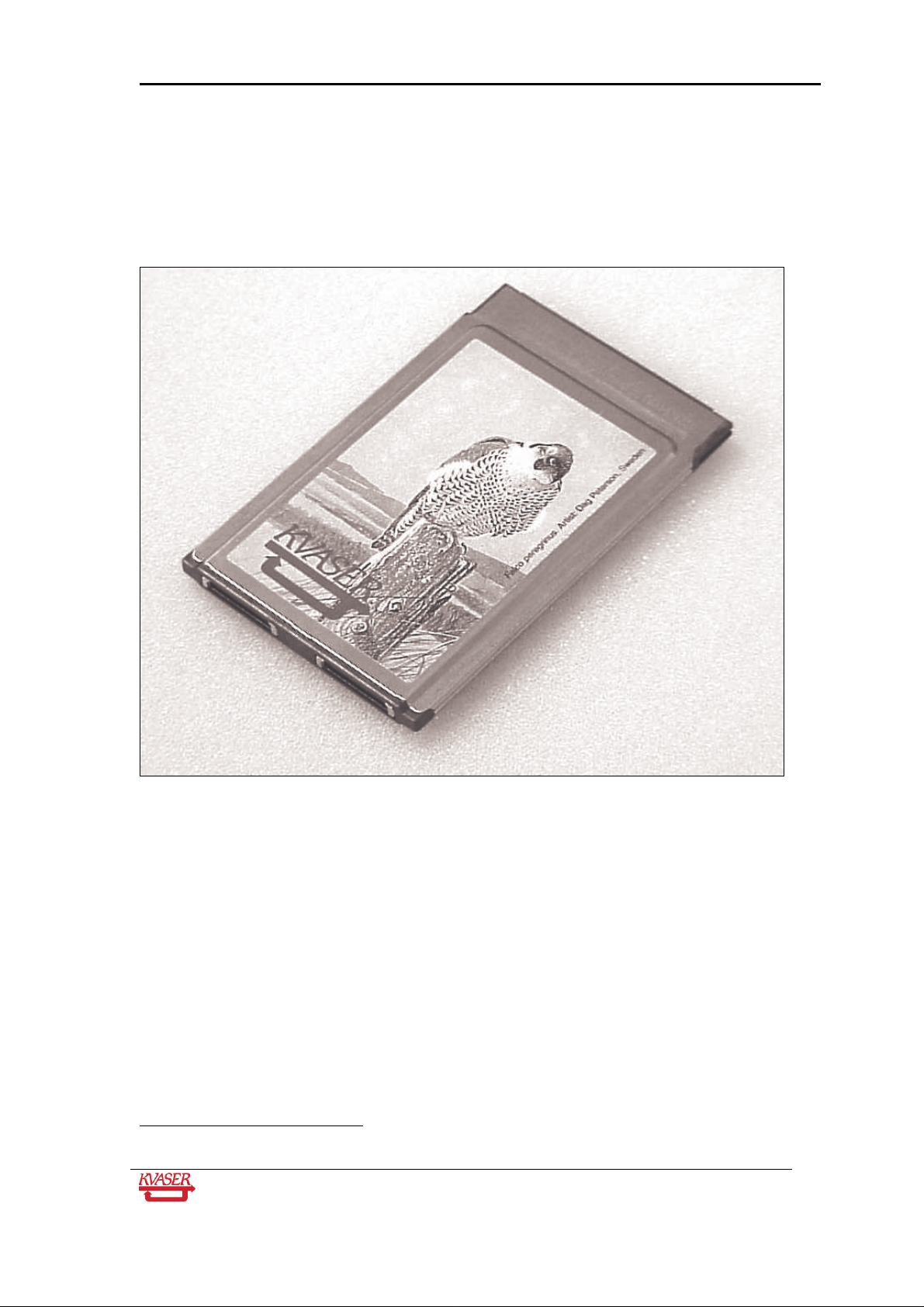
Kvaser LAPcan is a PC card compliant with the PC-Card (PCMCIA) standard. It contains the
powerful microcontroller C161O from Infineon and two SJA1000 CAN controllers from Philips.
The SJA1000 handles CAN messages with 11 bit as well as 29 bit identifiers. Remote frames
can be sent and received without restrictions. Kvaser LAPcan can both detect and generate
error frames on the CAN bus. Kvaser LAPcan provides two completely independent CAN
channels with two separate connectors. The CAN bus transceivers are integrated into the
connection cables.
The Kvaser LAPcan II is an improved version of the Kvaser LAPcan card. It
is fully compatible with the Kvaser LAPcan card but features
- better performance
- improved EMC and ESD characteristics
- a different artwork on the housing (an eagle instead of a peregrine falcon)
In this text we will use the name Kvaser LAPcan for both Kvaser LAPcan and
Kvaser LAPcan II.
Kvaser AB, Mölndal, Sweden — www.kvaser.com
Page 6
Kvaser LAPcan / LAPcan II Hardware Guide 6(19)
2
4 Kvaser LAPcan installation
The Kvaser LAPcan card may be inserted in any free PC Card (PCMCIA) slot
that is capable of accommodating Type II or Type III cards. You don’t have to
switch the power off before inserting or removing the card.
1
Figure 1. A Kvaser LAPcan with its two CAN ports.
Many new laptop computers are equipped with CardBus slots instead of
PCMCIA slots. You can use a CardBus slot for Kvaser LAPcan without
problems, because the CardBus controller will automatically use a special
compability mode for Kvaser LAPcan (or other PCMCIA cards)1.
The Kvaser LAPcan has two independent I/O ports that are depicted in the
figure above. You connect the card to the CAN network by means of special
cables, the DRVcans.
1
This is true for Windows 95, 98, ME, 2000 and XP. Windows NT 4.0 might have trouble with a
CardBus controller; please consult the computer manufacturer for more information.
Kvaser AB, Mölndal, Sweden — www.kvaser.com
Page 7

Kvaser LAPcan / LAPcan II Hardware Guide 7(19)
5 Technical data, Kvaser LAPcan and Kvaser LAPcan II
CAN channels 2 (CAN 2.0A and 2.0B active)
CAN Transceivers The transceivers are integrated into the DRVcans.
CAN Controllers Philips SJA 1000
Microcontroller Siemens SAB-C161O (16 MHz)
Baudrate 5 kbit/s ... 1 Mbit/s
Timestamp resolution 8 s
Error Frame Detection Yes, both channels
Error Frame Generation Yes, both channels
Hardware requirements IBM PC AT or 100% compatible; PC-Card slot type II
or III
PC interface PC-Card Version 2.0 (PCMCIA) or compatible
Current consumption 110 mA for the Kvaser LAPcan plus the current of the
DRVcans
Software requirements Windows 95 / Windows NT 4.0 or later
Configuration Done by software (Plug & Play if OS supports it.)
Dimensions PC-Card type II (ca. 85 mm x 64 mm x 5 mm)
Operating temperature 0 ºC ... +55 ºC
Non-operating
-25 ºC ... +70 ºC
temperature
Relative Humidity 0% ... 85% (non condensing.)
Kvaser AB, Mölndal, Sweden — www.kvaser.com
Page 8

Kvaser LAPcan / LAPcan II Hardware Guide 8(19)
6 The DRVcans
The DRVcans contain the CAN bus transceiver. There are several different
types of DRVcans, and which one to choose depends on the physical layer
your CAN system is using.
Figure 2. A typical DRVcan.
Kvaser AB, Mölndal, Sweden — www.kvaser.com
Page 9

Kvaser LAPcan / LAPcan II Hardware Guide 9(19)
6.1 DRVcan Types
Currently available DRVcans include:
Name
DRVcan 251 Industry-standard highspeed 82c251 transceivers;
DSUB connector according to the CiA standard.
DRVcan 1053 Industry-standard lowspeed TJA1053
transceivers; DSUB connector according to the
CiA standard.
DRVcan 1054 Industry-standard lowspeed TJA1054
transceivers; DSUB connector according to the
CiA standard.
DRVcan 1054 Opto Industry-standard lowspeed TJA1054
transceivers; DSUB connector according to the
CiA standard. Optical isolation.
DRVcan DNopto Industry-standard highspeed 82c251 transceivers;
the CAN bus is galvanically isolated from the
inputs by means of optocouplers; DSUB
connector according to the CiA standard.
DRVcan S J2411 single-wire CAN (transceiver AU5790 or
similar.)
DRVcan S Opto J2411 single-wire CAN (transceiver AU5790 or
similar.) Optical isolation.
DRVcan Fi HS Industry-standard highspeed 82c251 transceivers;
the CAN bus is galvanically isolated from the
inputs by means of optic fibres; DSUB connector
according to the CiA standard.
DRVcan Fi LS Industry-standard lowspeed TJA1054
transceivers; the CAN bus is galvanically isolated
from the inputs by means of optic fibres; DSUB
connector according to the CiA standard.
DRVcan Fi SWC Industry-standard AU5790 transceivers; the CAN
bus is galvanically isolated from the inputs by
means of optic fibres; DSUB connector.
DRVcan LIN This is a driver for the LIN bus.
DRVcan T&T E-mail to sales@kvaser.com for more
information.
DRVcan EVA Cable + wire-wrap board; for developing your own
physical layer
Customer specific E-mail to sales@kvaser.com for more
information about custom-design DRVcans.
Kvaser AB, Mölndal, Sweden — www.kvaser.com
Page 10

Kvaser LAPcan / LAPcan II Hardware Guide 10(19)
6.2 How to use the DRVcan
• Push firmly to insert the connector on the DRVcan into Kvaser LAPcan.
• To remove the connector, push both tabs (see Figure 3 below) as deep as
possible and pull out the connector.
• We recommend that you remove the card before inserting or removing
DRVcans. This is because not all software will be able to handle a “hotswap”. No damage to your Kvaser LAPcan will happen, however, if you
insert or remove a DRVcan while the Kvaser LAPcan is inserted into your
computer.
Kvaser AB, Mölndal, Sweden — www.kvaser.com
Page 11

Kvaser LAPcan / LAPcan II Hardware Guide 11(19)
7 A Few Words of Caution
• Do not apply excessive force when inserting the card into the computer.
• Do not remove the card by pulling on the I/O cables.
• Always make sure the I/O connectors are firmly seated.
• When you remove a DRVcan, you must firmly press both the tabs (see Figure 3 below)
on the connector.
Figure 3. The I/O connector on a DRVcan. The tabs are marked with arrows.
The D-SUB connector
Figure 4. The DSUB connector on a DRVcan.
The CAN bus is connected to the 9-pin DSUB connector (see Figure 4 above)
on the DRVcan.
Kvaser AB, Mölndal, Sweden — www.kvaser.com
Page 12

Kvaser LAPcan / LAPcan II Hardware Guide 12(19)
Caution!
Always connect the ground pin on the D-SUB to the ground of your CAN bus.
Some laptop computers have AC power supplies that might destroy the
DRVcan unless it is properly grounded. Running the laptop from battery power
is usually OK even if the ground lines are not connected.
Kvaser AB, Mölndal, Sweden — www.kvaser.com
Page 13

Kvaser LAPcan / LAPcan II Hardware Guide 13(19)
8 DRVcan configuration
The DRVcan -251, -1053, and -1054 types have the following pin
configuration:
D-SUB pin
number
1 N/A Not connected.
2 Green CAN_L (low level @ dominant)
3 Brown GND
4 Orange Reserved, do not connect.
5 Black Shield
6 N/A Not connected.
7 Red CAN_H (high level @ dominant)
8 N/A Not connected.
Colour code Function
9 Yellow Not connected.
Pins 2, 3, 4, and 7 are protected by 250 mA fuses.
The DRVcan DNopto has the following pin configuration:
D-SUB pin
Colour code Function
number
1 N/A Not connected.
2 Green CAN_L (low level @ dominant)
3 Brown GND
4 Orange Reserved, do not connect.
5 Black Shield
6 N/A Not connected.
7 Red CAN_H (high level @ dominant)
8 N/A Not connected.
9 Yellow Optional external power, 11-25V.
Pins 2, 3, 4, and 7 are protected by 250 mA fuses.
Kvaser AB, Mölndal, Sweden — www.kvaser.com
Page 14

Kvaser LAPcan / LAPcan II Hardware Guide 14(19)
The DRVcan Fi HS has the following pin configuration:
D-SUB pin
Colour code Function
number
1 N/A Not connected.
2 Green CAN_L (low level @ dominant)
3 Brown GND
4 Orange Not connected.
5 Black Shield
6 N/A Not connected.
7 Red CAN_H (high level @ dominant)
8 N/A Not connected.
9 Yellow External power, 6-36V.
The DRVcan Fi LS has the following pin configuration:
D-SUB pin
Colour code Function
number
1 N/A Not connected.
2 Green CAN_L (low level @ dominant)
3 Brown GND
4 Orange Not connected.
5 Black Shield
6 N/A Not connected.
7 Red CAN_H (high level @ dominant)
8 N/A Not connected.
9 Yellow External power, 6-36V.
The DRVcan Fi SWC has the following pin configuration:
D-SUB pin
Colour code Function
number
1 N/A Not connected.
2 Green Not connected.
3 Brown GND
4 Orange Not connected.
5 Black Shield
6 N/A Not connected.
Kvaser AB, Mölndal, Sweden — www.kvaser.com
Page 15

Kvaser LAPcan / LAPcan II Hardware Guide 15(19)
7 Red CAN_H (high level @ dominant)
8 N/A Not connected.
9 Yellow External power, 6-36V.
Here is the pin configuration for the DRVcan-S:
D-SUB pin
Colour code Function
number
1 N/A Not connected.
2 Green Not connected.
3 Brown GND
4 Orange Reserved, do not connect.
5 Black Shield
6 N/A Not connected.
7 Red CAN_H (high level @ dominant)
8 N/A Not connected.
9 Yellow Power supply (nominal +12V DC; fully
functional between +7.5 and +18 V DC.)
Power is required.
Pins 3 and 4 are protected by 250 mA fuses.
Here is the pin configuration for the DRVcan LIN:
D-SUB pin
Colour code Function
number
1 N/A Not connected.
2 Green Not connected.
3 Brown GND
4 Orange LIN bus
5 Black Shield
6 N/A Not connected.
7 Red Reserved, do not connect.
8 N/A Not connected.
9 Yellow Power supply (nominal +12V DC; fully
functional between +7 and +18 V DC.)
Power is required.
Kvaser AB, Mölndal, Sweden — www.kvaser.com
Page 16

Kvaser LAPcan / LAPcan II Hardware Guide 16(19)
8.1 Technical Data for DRVcan 251
Transceiver type Philips 82c251
Current consumption 40 mA (average)
Maximum bus speed 1 Mbit/s
DRVcan 251 does not have built-in CAN bus termination.
8.2 Technical Data for DRVcan 1053
Transceiver type Philips TJA1053
Current consumption 20 mA (average)
Maximum bus speed 125 kbit/s
Built-in termination, RTH
Built-in termination, RTL
4.7 kΩ
4.7 kΩ
Note: the termination resistors RTH and RTL are optimized for bus analyzing tools. This means that
they do not load the bus enough to ensure proper signal levels if there are no other "real" nodes on the
bus. If you connect just two DRVcan 1053:s to a long (several meters) bus, the communication may or
may not work.
8.3 Technical Data for DRVcan 1054
Transceiver type Philips TJA1054
Current consumption 20 mA (average)
Maximum bus speed 125 kbit/s
Built-in termination, RTH
Built-in termination, RTL
4.7 kΩ
4.7 kΩ
Note: the termination resistors RTH and RTL are optimized for bus analyzing tools. This means that
they do not load the bus enough to ensure proper signal levels if there are no other "real" nodes on the
bus. If you connect just two DRVcan 1054:s to a long (several meters) bus, the communication may or
may not work.
8.4 Technical Data for DRVcan DNopto
Transceiver type Philips 82c251
Current consumption 80 mA (average)
Maximum bus speed 1 Mbit/s
Optocoupler type HCPL 7101-3
Optocoupler delay 20 ns
Isolation voltage 50 V AC, 70 V DC
The transceiver in the DRVcan DNopto can be powered either from the Kvaser LAPcan, or externally
by connecting a power source to pin 9 on the D-SUB.
There is no built-in CAN bus termination in the DRVcan DNopto.
Kvaser AB, Mölndal, Sweden — www.kvaser.com
Page 17

Kvaser LAPcan / LAPcan II Hardware Guide 17(19)
8.5 Technical Data for DRVcan Fi
Transceiver type Philips 82c251
Current consumption 50 mA (average, bus side), 50 mA at 125
kbps, 100 mA at 1 Mbps (average, laptop
side)
Maximum bus speed 1 Mbit/s (depending on fibre length and
properties of the complete network)
Optic driver type HFBR 2528
Total delay 360 ns + 2*5 ns/meter of fibre
Isolation voltage Depending on fibre length and quality
The transceiver in the DRVcan Fi must be powered both from the Kvaser LAPcan, and externally by
connecting a power source to pin 9 on the D-SUB.
The DRVcan Fi is delivered with 10 m of high-grade plastic fibre.
The is no built-in CAN bus termination in the DRVcan Fi.
8.6 Technical Data for DRVcan S
Transceiver type Philips AU5790 or similar
Current consumption Built-in bus pull-up consumes approx. 5
mA; the CAN bus driver consumes approx.
7.5 mA.
External power +7.5 V ... +18 V DC. Nominal voltage is 12
V DC.
Note: external power (12V) is required to make the DRVcan S work.
8.7 Technical Data for DRVcan LIN
Transceiver type MC 33399
Current consumption TBD.
External power +7 V ... +18 V DC.
Note: external power (12V) is required to make the DRVcan LIN work.
Kvaser AB, Mölndal, Sweden — www.kvaser.com
Page 18

Kvaser LAPcan / LAPcan II Hardware Guide 18(19)
9 EMC Compliance
EMC Tests
The equipment has been tested for compliance with the EN 50 081-2:1993 (emission) and the
EN 50 082-2:1995 (immunity) standards.
NOTE: This equipment has been tested and found to comply with the limits for a Class A
digital device, pursuant to Part 15 of the FCC Rules. These limits are designed to provide
reasonable protection against harmful interference when the equipment is operated in a
commercial environment. This equipment generates, uses, and can radiate radio frequency
energy and, if not installed and used in accordance with the instruction manual, may cause
harmful interference to radio communications. Operation of this equipment in a residential
area is likely to cause harmful interference in which case the user will be required to correct
the interference at his own expense.
Kvaser AB, Mölndal, Sweden — www.kvaser.com
Page 19

Kvaser LAPcan / LAPcan II Hardware Guide 19(19)
10 Document revision history
Revision Date Changes
1 2003-12 Original revision
2 2006-10-27 Reviewed – added DRVcan Fi versions
Kvaser AB, Mölndal, Sweden — www.kvaser.com
 Loading...