

Philips KX-NCP500, KX-NCP1000 User Manual

Model No.
KX-NCP500/KX-NCP1000
Pure IP-PBX
Thank you for purchasing a Panasonic Pure IP-PBX.
Please read this manual carefully before using this product and save this manual for future use.
KX-NCP500/KX-NCP1000: PBMPR Software File Version 1.0000 or later
In this manual, the suffix of each model number (e.g., KX-NCP500NE) is omitted unless necessary.
Programming Manual
for Virtual SIP Trunk Card

Table of Contents
Table of Contents
1 Overview ..
1.1 Information about IP Telephony Service ........................................................................4
1.2 Important Notice for Subscription and Installation .......................................................7
1.2.1 Port Requirements ...........................................................................................................7
1.2.2 Firewall Requirements ......................................................................................................7
1.2.3 Bandwidth Requirements .................................................................................................8
1.3 Specifications ....................................................................................................................9
.................................................................................................3
2 Preparations for PC Programming .......................................................11
2.1 Maintenance Console Operating Instructions ..............................................................12
2.1.1 Installing and Starting the Maintenance Console ...........................................................12
2.2 Installing the V-SIPGW16 Card to the PBX ...................................................................16
3 Programming the V-SIPGW16 Card ......................................................17
3.1 Programming the V-SIPGW16 Card—Port Property ....................................................18
3.1.1 Main ................................................................................................................................19
3.1.2 Account ..........................................................................................................................20
3.1.3 Register ..........................................................................................................................21
3.1.4 NAT ................................................................................................................................23
3.1.5 Option .............................................................................................................................24
3.1.6 Calling Party ...................................................................................................................25
3.1.7 Called Party ....................................................................................................................27
3.1.8 Voice/FAX ......................................................................................................................27
3.1.9 RTP/RTCP .....................................................................................................................30
3.1.10 T.38 ................................................................................................................................31
3.1.11 T.38 Option .....................................................................................................................32
3.1.12 DSP ................................................................................................................................34
3.1.13 Supplementary Service ..................................................................................................35
3.2 Programming the V-SIPGW16 Card—Card Property ...................................................37
3.2.1 Card Property .................................................................................................................37
3.3 Programming the V-SIPGW16 Card—Shelf Property ..................................................40
3.3.1 Main ................................................................................................................................40
3.3.2 Timer ..............................................................................................................................42
4 Maintenance ...........................................................................................45
4.1 Configuration Management ............................................................................................46
4.1.1 Importing/Exporting V-SIPGW16 Provider Profiles ........................................................46
4.1.2 V-SIPGW16 Protocol Trace ...........................................................................................47
Index..............................................................................................................49
2 Programming Manual for Virtual SIP Trunk Card

Section 1
Overview
This section provides an overview of the V-SIPGW16
card.
Programming Manual for Virtual SIP Trunk Card 3
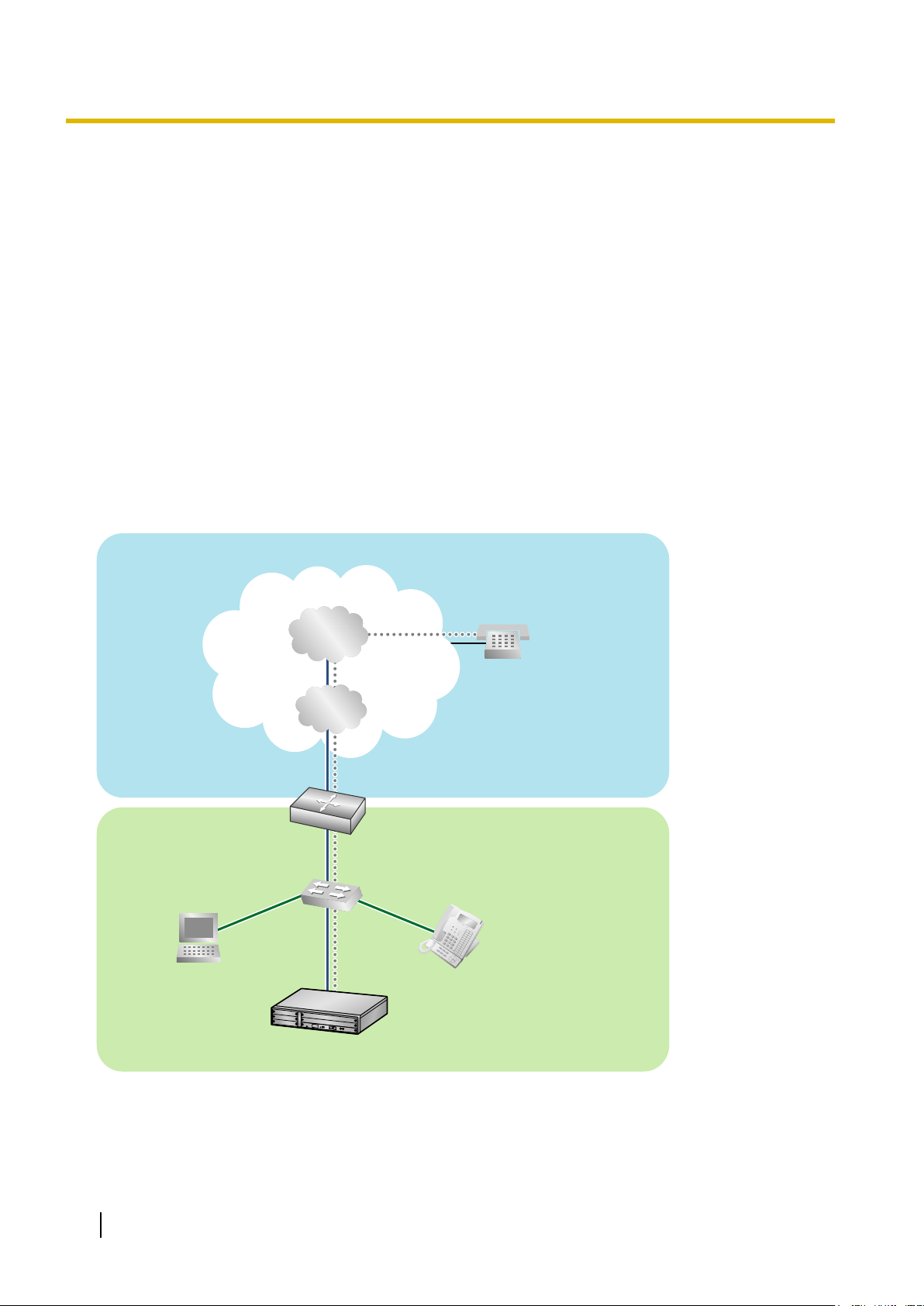
PBX with
V-SIPGW16 Card
PC
LAN
(Local Area Network)
WAN (Wide Area Network)
Internet
Local
Telephone
IP-PT
ISP
ITSP
Router
Switching
Hub
1.1 Information about IP Telephony Service
1.1 Information about IP Telephony Service
The Virtual 16-Channel SIP Trunk Card (V-SIPGW16) is a virtual trunk card which is designed to be easily
integrated into an Internet Telephony Service provided by an ITSP (Internet Telephony Service Provider).
As a major SIP Provider, an ITSP provides its telephony service partly through the conventional telephone
network (e.g., ISDN and Mobile), which is fee-based. An ISP (Internet Service Provider), another major SIP
Provider, does not provide telephone connection itself. However, providing its users with Internet access, an
ISP
provides voice communication on the Internet for free. In this way, with VoIP technology based on the SIP
protocol, the cost of voice communication can be much cheaper than conventional telephone networks.
The maximum number of V-SIPGW16 cards that can be installed in the virtual trunk slots of the PBX is one
for the KX-NCP500 and two for the KX-NCP1000.
The channel capacity of the card allows KX-NCP500 users to connect to up to 8 different ISP/ITSPs and allows
KX-NCP1000 users to connect to up to 32 different ISP/ITSPs.
V-SIPGW16 Connection Outline
The following diagram illustrates a simple VoIP network connecting the V-SIPGW16 card to the Internet.
Requirements for Internet Telephony Service
• You need to subscribe with an ISP for Internet connection.
• You need
company.
4 Programming Manual for Virtual SIP Trunk Card
to subscribe with an ITSP for telephone connection. The ISP and ITSP may be part of the same

1.1 Information about IP Telephony Service
Note
• VoIP communication
using the V-SIPGW16 card may deteriorate depending on the ITSP being used.
• VoIP communication using the V-SIPGW16 card may deteriorate depending on the network conditions.
DNS (Domain Name System)
A DNS server normally provides the name resolution service for your computer. As domain names are
alphabetic, they are easier to remember. The Internet, however, is based on IP addresses. Therefore, every
time a domain name is used, a DNS server must translate the name into the corresponding IP address, and
vice versa. For example, the domain name www.example.com may be translated to 192.0.34.166. If one DNS
server does not know how to translate a particular domain name, it asks another one, and so on, until the
correct IP address is returned.
NAT (Network Address Translation) Traversal
When NAT/NAPT (Network Address Port Translation) is enabled, the router translates a local IP address from
the PBX into a global IP address. However, the router with NAT enabled does not translate local IP addresses
stored in SIP messages into global IP addresses.
Therefore, the address which the SIP Server recognises as the destination IP address to reply to is actually
the local IP address of the PBX, not the global IP address of the router. Therefore, if the SIP server receives
a SIP message from the PBX and sends a message back to the PBX using the address stored in the SIP
message, the packet information will not reach the PBX.
STUN Servers function to solve the global IP address problem under certain NAT conditions, for example, in
case of full duplex communication. A STUN Server, used alongside the SIP Server, finds out the global IP
address of the router with NAT enabled. With the STUN feature enabled, the packet information sent by the
SIP Server is able to "traverse" NAT and reach the PBX.
The settings can be configured to specify whether to enable the NAT Traversal feature for each ISP/ITSP. In
addition, the NAT Traversal method can be selected from "STUN" and "Fixed IP Address" (refer to
3.3.1 Main, NAT Traversal).
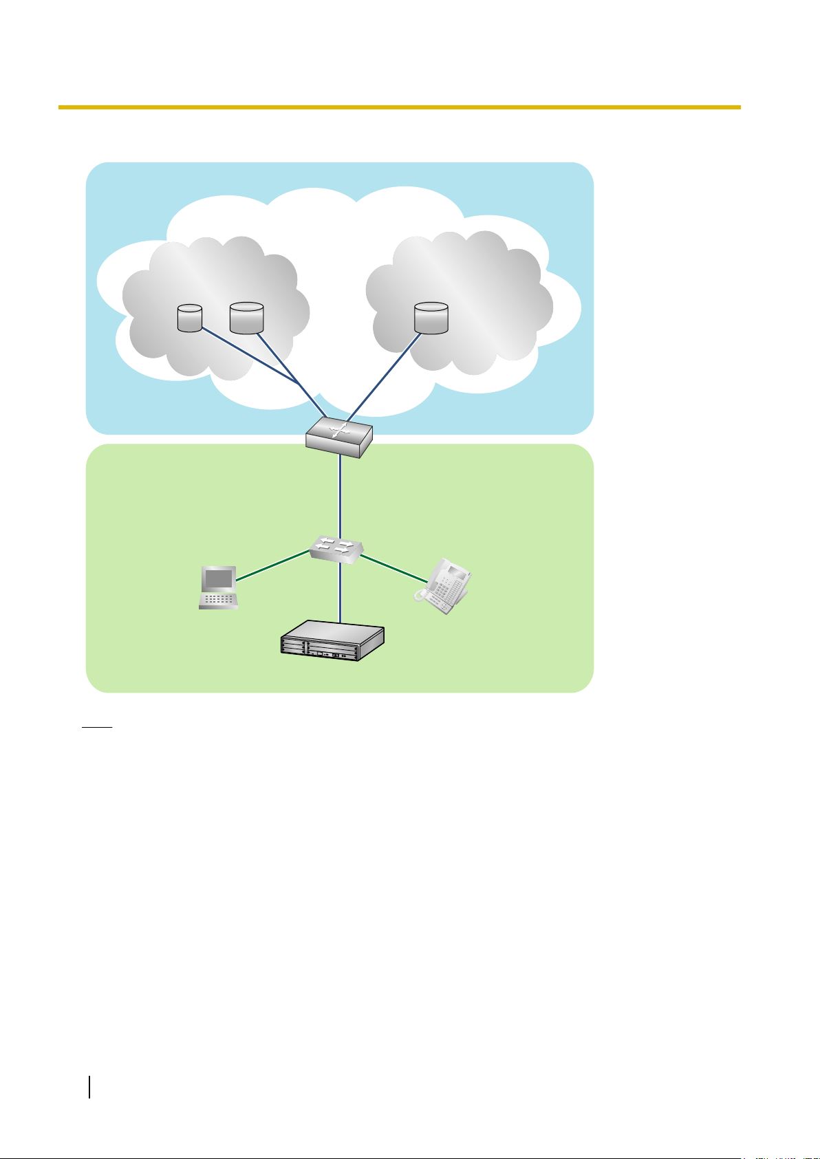
The V-SIPGW16 card may require the NAT Traversal feature to be enabled to connect to the WAN via a router.
The following diagram illustrates how VoIP communication is enabled between the V-SIPGW16 card and the
SIP Server (SIP Receiver) via a router with NAT enabled.
Programming Manual for Virtual SIP Trunk Card 5
LAN
WAN
Internet
STUN
STUN
STUN
STUN
Server
Server
SIP
SIP
Server
Server
Fixed IP Address
Fixed IP Address
SIP
SIP
Server
Server
STUN
STUN
Server
SIP
Server
Fixed IP Address
SIP
Server
PBX with
V-SIPGW16 Card
ISP/ITSP
ISP/ITSP
ISP/ITSP
ISP/ITSP
ISP/ITSP
ISP/ITSP
Router
(NAT enabled)
PC
IP-PT
Switching
Hub
1.1 Information about IP Telephony Service
Note
• If an ISP/ITSP uses a device such as SBC (Session Border Controller), you may not have to enable
the NAT Traversal feature.
• A STUN Server is supplied by an ISP/ITSP, and not included with the PBX.
6 Programming Manual for Virtual SIP Trunk Card

1.2.2 Firewall Requirements
1.2 Important Notice for Subscription and Installation
1.2.1 Port Requirements
Required Ports for Each Channel
When configuring a router with NAT enabled, you need to secure a certain number of ports for each SIP and
RTP/RTCP channel.
(Ch). For SIP signalling, the number of required ports is always one regardless of the number of activated SIP
trunks (Ch).
<Example>
If 4 SIP trunk channels are activated, you need the following number of ports:
Protocol Type Required Port
RTP 4
RTCP 4
SIP 1
Total 9
For RTP/RTCP, the number of required ports is double the number of activated SIP trunks
1.2.2 Firewall Requirements
If the VoIP network contains a firewall, you must configure the firewall to allow VoIP packets to pass through
certain ports of the ports listed below without being blocked by filtering. The ports for which you need to
configure the firewall may vary depending on the network conditions.
For more information, consult your network administrator.
[IP Packets to V-SIPGW16 Card]
Port TCP/UDP Default Port No.
SIP Client Port UDP 35060
STUN Client Port UDP 33478
NAT Voice (RTP) UDP Port UDP 16000 to N
DNS (Client) Port UDP 30053
[IP Packets from V-SIPGW16 Card]
Port TCP/UDP Default Port No.
SIP Server Port UDP 5060
Registrar Server Port UDP 5060
STUN Server Port UDP 3478
Manual DNS Server Port UDP 53
Programming Manual for Virtual SIP Trunk Card 7

1.2.3 Bandwidth Requirements
Router Requirements
• Port Forwarding:
It may
be necessary to set the NAT router so that it forwards the incoming packets to the IP address of the
V-SIPGW16 card if all of the following conditions are met:
– the PBX uses a STUN server;
– a V-SIPGW16 card is located under a NAT router;
– incoming packets are routed to a SIP Client port or NAT Voice (RTP) UDP port indicated in the [IP
Packets to V-SIPGW16 Card] table above.
• SIP-NAT Feature:
When a V-SIPGW16 card is located under a NAT router that supports the SIP-NAT feature*1, it is
recommended to disable this feature.
*1
When NAT is enabled, the router translates the IP address stored in the IP header and the port number stored in the UDP header.
When SIP-NAT is enabled, the router also translates the IP address and port number stored in SIP messages.
1.2.3 Bandwidth Requirements
When using the V-SIPGW16 card, you must ensure that the WAN has enough bandwidth to support VoIP
communications. Refer to the table below and ensure that the sum of the required bandwidth for each channel
is smaller than the amount the WAN (e.g., ADSL network) can provide.
Note that the amount in the table is only a guide. Subscribe to a network that has enough bandwidth. If the
amount of bandwidth required for VoIP communications is larger than what the network can accommodate,
speech quality will be compromised.
Required Bandwidth for Each Channel
The required bandwidth depends on what combination of CODECs and packet sending interval is used. Keep
in mind the following points about the type of CODEC and packet sending interval, in terms of the speech
quality:
• The speech quality of the CODECs varies as follows: G.711 (High), G.729 (Low)
• The shorter the packet sending interval, the higher the speech quality.
• The higher the speech quality the V-SIPGW16 card provides, the more bandwidth the WAN requires.
Packet Sending Interval
CODEC
10 ms 20 ms 30 ms 40 ms 50 ms 60 ms
G.711 110.4 kbps 87.2 kbps 79.5 kbps 75.6 kbps 73.3 kbps 71.7 kbps
G.729 54.4 kbps 31.2 kbps 23.5 kbps 19.6 kbps 17.3 kbps 15.7 kbps
8 Programming Manual for Virtual SIP Trunk Card

1.3 Specifications
1.3 Specifications
For details about the RFCs and protocols for the V-SIPGW16 card, refer to the following specifications.
Items Specification
SIP RFCs RFC3261 (UDP only)
RFC3262 (PRACK)
RFC3264 (Offer/Answer)
RFC3311 (UPDATE)
RFC3581 (Symmetric Response Routing/rport)
RFC4028 (Session Timer)
CODECs G.711 (a-law and µ-law)
G.729A
Voice Options Echo Cancellation (48 ms)
Jitter Buffer (200 ms)
VAD (Voice Activity Detection)
PLC (Packet Loss Concealment)
DTMF Relay Inband/Outband (RFC2833)/Outband (INFO)
Fax Relay G.711 Inband/T.38
Protocol/Function RTP
RTCP
DNS (A/SRV)
NAT Traversal (STUN)
QoS (ToS field setting in IP header of RTP/RTCP)
Programming Manual for Virtual SIP Trunk Card 9

1.3 Specifications
10 Programming Manual for Virtual SIP Trunk Card

Section 2
Preparations for PC Programming
This section serves as reference operating instructions
when using the Maintenance Console software to
programme the V-SIPGW16 card.
Programming Manual for Virtual SIP Trunk Card 11

2.1.1 Installing and Starting the Maintenance Console
2.1 Maintenance Console Operating Instructions
2.1.1 Installing and Starting the Maintenance Console
System programming,
the Maintenance Console. This section describes how to install and start the Maintenance Console.
diagnosis and administration for the V-SIPGW16 card can be performed with a PC using
System Requirements
Required Operating System
• Microsoft
®
Windows® XP or Windows Vista® Business
Minimum Hardware Requirements
• HDD: 100 MB of available hard disk space
Recommended Display Settings
• Screen resolution: XGA (1024 ´ 768)
• DPI setting: Normal size (96 DPI)
Hardware Requirements
• Make sure that the PBX, IPCMPR card, and DSP card are installed.
• Make sure that the PBX is fully connected to your PC.
Note
For details about installation, refer to "Section 3 Installation" in the Installation Manual.
Trademarks
• Microsoft, Windows and Windows Vista are either registered trademarks or trademarks of Microsoft
Corporation in the United States and/or other countries.
• All other trademarks identified herein are the property of their respective owners.
• Microsoft product screen shot(s) reprinted with permission from Microsoft Corporation.
Copyright for MD5
This software uses the Source Code of RSA Data Security, Inc. described in the RFC1321
(MD5Message-Digest Algorithm).
Copyright (C) 1991-2, RSA Data Security, Inc. Created 1991. All rights reserved.
Licence to copy and use this software is granted provided that it is identified as the "RSA Data Security, Inc.
MD5 Message-Digest Algorithm" in all material mentioning or referencing this software or this function.
Licence is also granted to make and use derivative works provided that such works are identified as "derived
the RSA Data Security, Inc. MD5 Message-Digest Algorithm" in all material mentioning or referencing the
from
derived work.
12 Programming Manual for Virtual SIP Trunk Card

2.1.1 Installing and Starting the Maintenance Console
RSA Data Security, Inc. makes no representations concerning either the merchantability of this software or
the suitability
of any kind.
These notices must be retained in any copies of any part of this documentation and/or software.
of this software for any particular purpose. It is provided "as is" without express or implied warranty
Installing the Maintenance Console
Note
• Make sure to install and use the latest version of the Maintenance Console.
• To install or uninstall the software on a PC running Windows XP Professional, you must be logged in
as a user in either the "Administrators" or "Power Users" group.
• To install or uninstall the software on a PC running Windows Vista Business, you must be logged in
as a user in the "Administrators" group.
• Product specifications, including text displayed by the software, are subject to change without notice.
1. Copy the setup file of the Maintenance Console to your PC.
2. Double-click the setup file to run the installer.
3. Follow the on-screen instructions provided by the installation wizard.
Starting the Maintenance Console and Assigning the Basic Items (Quick
Setup)
When you start the Maintenance Console with the Installer Level Programmer Code and connect to the PBX
the
first time after initialisation (with the factory default setting), Quick Setup will launch automatically. During
for
Quick Setup, you will set up the basic items. For details about the basic items, refer to "2.3.4 Quick Setup" in
the Feature Guide.
1. Connect the PC to the PBX with an Ethernet straight cable or RS-232C cross cable.
2. Start the Maintenance Console from the Start menu.
3. "Information before programming" appears.
a. Carefully read this important additional information, which includes updates to this and other
manuals.
b. Click OK to close this window.
4.
a. Enter the Installer Level Programmer Code (default: INSTALLER).
b. Click OK.
5. Click Connect.
6.
a. Select KX-NCP500/1000 from PBX Model.
b. Select the LAN or RS-232C tab, depending on the type of PC connection with the PBX.
c. Specify the settings as required.
Note
When connecting to the PBX for the first time selecting LAN, the IP Address and Port
Number must be set to 192.168.0.101 and 35300 respectively.
d. Enter the system password for installer (default: 1234).
e. Click Connect.
Programming Manual for Virtual SIP Trunk Card 13

2.1.1 Installing and Starting the Maintenance Console
7. When country/area data do not match:
a. Click OK to
replace the country/area data of the PBX. Replacement may take several minutes to
complete.
b. Follow the procedure described in Section "3.16.1 Starting the PBX" in the Installation Manual
and restart the PBX.
c. Repeat step 5 to reconnect the Maintenance Console to the PBX.
8. Follow the instructions of the Quick Setup wizard for the basic items in Quick Setup—Step 1 to 3.
9. In Quick Setup—Step 4, the IP addressing information for the IPCMPR card can be assigned
automatically through a DHCP server or entered manually.
When using a DHCP server:
a. Select Enable for the DHCP Client setting.
b. Click Apply.
Note
The boxes
will turn grey and the IP addresses will be assigned automatically after the PBX is reset.
When not using a DHCP server:
a. Select Disable for the DHCP Client setting.
b. In the IP Address for IPCMPR Card box, type the IP address of the IPCMPR card.
c. In the IP Address for VoIP-DSP box, type the IP address of the DSP16 or DSP64 card.
d. In the Subnet Mask box, type the subnet mask address of the network.
e. In the Default Gateway box, type the IP address of the default gateway.
*3
*4
f. Click Apply.
*1
*2
When using a DHCP server to obtain a DNS server IP address automatically:
a. Select DHCP for the DNS Server Address Method setting.
b. Click Apply.
Note
The boxes
will turn grey and the IP addresses will be assigned automatically after the PBX is reset.
14 Programming Manual for Virtual SIP Trunk Card

2.1.1 Installing and Starting the Maintenance Console
When not using a DHCP server to obtain a DNS server IP address automatically:
a. Select Manual for the DNS Server Address Method setting.
b. In the Manual
server.
Preferred DNS Server IP Address box, type the IP address of the preferred DNS
c. In the Manual Alternate DNS Server IP Address box, type the IP address of the alternate DNS
server.
d. Click Apply.
The system menu appears. You may now begin programming the PBX.
Notice
• Do not change the IP addresses of the IPCMPR and DSP cards once IP telephones are
registered to the PBX using these IP addresses.
The IP telephones will not operate properly if these IP addresses are changed.
• A DHCP server must be able to use a "client identifier" option specified by RFC 2131.
• The PBX will not start properly if the IP addresses cannot be assigned automatically by the
DHCP server when DHCP Client is set to Enable. In this case, you need to consult your
network administrator because the DHCP server on your network may not be running or a
network
Client setting to Disable and set fixed IP addresses, then restart the PBX.
To change the DHCP Client setting, connect the PC with an RS-232C cross cable or Ethernet
straight cable. When connecting the PC with an Ethernet straight cable, make sure the PBX
is disconnected from the LAN and then connect the PC with an Ethernet straight cable using
192.168.0.101 for the IP address of the IPCMPR card.
failure may have occurred. If the DHCP server cannot be available, change the DHCP
*1
Valid IP address range: "1.0.0.0" to "223.255.255.255"
*2
Valid IP address range: "1.0.0.0" to "223.255.255.255"
*3
Valid subnet mask address range: "0–255.0–255.0
*4
Valid IP address range: "1.0.0.0" to "223.255.255.255"
–255.0–255" (except 0.0.0.0 and 255.255.255.255)
Programming Manual for Virtual SIP Trunk Card 15

2.2 Installing the V-SIPGW16 Card to the PBX
2.2 Installing the V-SIPGW16 Card to the PBX
1.
a. Under Configuration, click Slot.
b. Move the mouse pointer over the PBX image of IPCMPR Virtual Slot at the top of the screen.
c. Click Select Shelf.
2.
a. Click on the name of the V-SIPGW16 card. An image of the card will be displayed.
b. Drag the image of the card to a Trunk slot and release it. The card will move into the slot space.
3. Click Yes to confirm.
16 Programming Manual for Virtual SIP Trunk Card
 Loading...