

Page 1

Industrial Vision
Intelligent Camera
12 NC: 8122 410 5693.0
-
Philips Applied Technologies
Inca 320
Hardware
Manual
Page 2

Inca 320 Hardware Manual
Version 1.0
A publication of:
Philips Applied Technologies
www.apptech.philips.com/industrialvision
© 2005 Philips Electronics N.V.
Eindhoven, The Netherlands
All rights are reserved.
Reproduction in whole or in part is prohibited without the written consent of the copyright owner.
The information in this publication is furnished for guidance, and with no guarantee as to its accuracy or
Philips Applied Technologies does not assume liability for any consequences to its use;
specifications and availability of goods mentioned in it are subject to change without notice
Printed in the Netherlands, 2005-12-12
Industrial Vision
completeness.
8122 410 5699.0
Page 3

CONTENTS
Inca 320 Hardware Manual...............................................................................................................................2
1 INTRODUCTION ........................................................................................................................................3
1.1 ABOUT THIS MANUAL...............................................................................................................3
1.2 SUPPLIED PARTS......................................................................................................................3
1.3 ABOUT THE INSTALLATION .....................................................................................................3
2 HARDWARE ..............................................................................................................................................4
2.1 TRIMEDIA PROCESSOR ........................................................................................................... 4
2.2 CMOS SENSOR .........................................................................................................................5
2.3 CAMERA CONNECTIONS ......................................................................................................... 5
2.4 POWERING UP ........................................................................................................................12
3 SOFTWARE INSTALLATION.................................................................................................................. 14
4 CONFIGURATION ...................................................................................................................................15
4.1 TCP/IP.......................................................................................................................................15
4.2 Configuring TCP/IP ...................................................................................................................15
4.3 Port Number..............................................................................................................................15
4.4 Special configurations ...............................................................................................................15
4.5 Firewall......................................................................................................................................17
4.6 Default Configuration................................................................................................................. 17
5 MECHANICAL INTERFACE....................................................................................................................18
6 TROUBLE SHOOTING............................................................................................................................ 19
6.1 KNOWN PROBLEMS USING THE INCA.................................................................................. 19
Page 4

6.2 SERVICE AND SUPPORT........................................................................................................20
7 TECHNICAL SPECIFICATION.................................................................................................................21
Page 2 2005-12-12
Page 5

1 INTRODUCTION
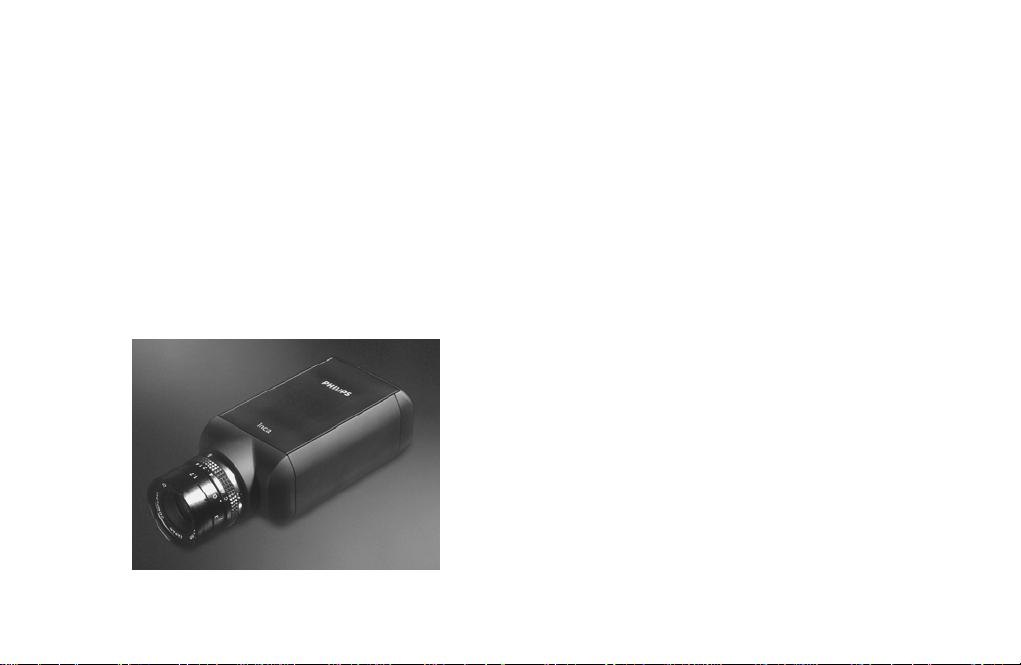
Congratulations on buying the Inca vision system!
An Inca is a high quality intelligent camera for image
acquisition and processing. Inca offers a complete vision
system that is ACCURATE, FAST, COMPACT and COSTEFFECTIVE. The high-resolution, high dynamic range
sensor provides the best basis for the development of a
very accurate vision system. Having all the processing
power close to the sensor and the capability of region of
interest processing reduces processing time and th us
faster systems can be realised. Because of this integrated
processor, display capabilities and industrial I/O, the Inca
offers a very compact total vision solution, without any
need for additional hardware like e.g. a PC. This makes an
Inca solution besides very cost-effective also transparent
and easy to work with. Finally the industrial housing
provides optimal possibilities for incorporating the Inca in
almost every (industrial) environment.
1.2 SUPPLIED PARTS
The supplied equipment comprises the following:
• One Inca 320 camera.
• One hardware manual (this document).
If any of these items is not included notify your supplier
immediately.
1.3 ABOUT THE INSTALLATION
The installation consists only of making the right
connections to the Inca. Start-up and running an
application is completely done under software control.
Software is not provided with the Inca, but is a separate
product that can be purchased from Industrial Vision. Refer
to chapter 3 for available software.
1.1 ABOUT THIS MANUAL
This manual explains how to install your Inca camera and
how to check that it is working correctly.
2005-12-12 Page 3
Page 6
2 HARDWARE
The Inca hardware consists of the following modules:
• TriMedia processor
• CMOS sensor
• Ethernet 10BaseT/100BaseT interface
• RS232 serial interface
• Video outputs VGA and CVBS
• Digital inputs and outputs
• Trigger input and flashlight output
• Reset input and watchdog output
• Four general purpose LEDs
• One system LED
• 8 MByte on-board flash memory
• 32 MByte SDRAM
2.1 TRIMEDIA PROCESSOR
The core of the Inca is the TriMedia 1300 processor. This
Very Long Instruction Word CPU (max. 5 parallel
instructions) with image co-process or run s on 18 0 M H z.
Among others, this processor handles:
Image and control data flows
Storage of acquired images. The images are stored in the
32 MByte on-board SDRAM.
Processing of the image stored in on-board SDRAM
Interaction with its environment for product information and
measurement results
Programming this TriMedia processor can be done using
the Rhapsody C/C++ software package or a graphic al
development environment called Clicks. The TriMedia part
of this software is based on the real time operating system
pSos™. Especially for high-end vision applications this is
very important, because in this way the timing of the
application is deterministic, this in contrast to programs
running in Windows™.
Clicks allows application engineers to graphically compose
the tasks to perform. Without the need of programming
expertise this tool is easily accessible for most engineers
and offers a very natural and interactive way to realize your
application.
Page 4 2005-12-12
Page 7
• Digital input 6 bits optically isolated
2.2 CMOS SENSOR
2.2.1 Inca 320
In the Inca 320 a monochrome sensor IBIS5A-1300 from
FillFactory is implemented. This sensor is dedicated to
industrial machine vision solutions and has both a rolling
and a synchronous shutter. High dynamical range scenes
can be captured using the double or multiples slope
functionality. The following main features, supported by the
Inca 320, are available:
• 1280 x 1024 Pixels
• 10 bit 40 Msample ADC resolution
• 2/3” sens or housing
• One region of interest
• Programmable exposure time
• 10, 20 or 40 MHz pixelclock
• Full framerate 27 frames per second
• Optical dynamic range 64 dB in single slope,
up to 100 dB in multi slope.
• Synthetic test image
• Decimation factor 2 for higher frame rates of sub-
sampled images
• Digital output 6 bits optically isolated
• RS232
• Camera reset
• Watchdog
• VGA and CVBS for display purposes
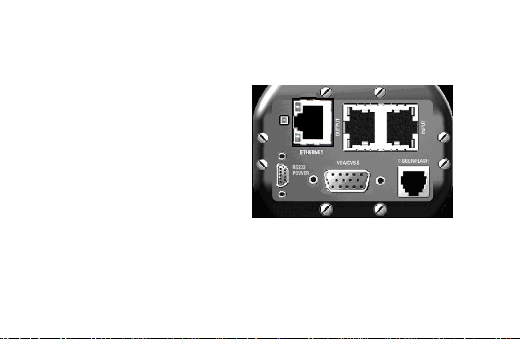
Figure 2-1 Inca 320 back side connectors
2.3 CAMERA CONNECTIONS
The rear side of the camera gives the user a great number
of possibilities for interfacing the camera.
• 10BaseT/100BaseT Ethernet
• One trigger input and one output for flash control
2005-12-12 Page 5
Page 8

2.3.1 10BaseT/100BaseT
For the interconnection of the Inca camera to the host PC
a so-called 10BaseT (for 10Mbs) or 100BaseT (for
100Mbs) connection is used, which is a twisted pair
connection for Ethernet. For this link the PC must be
equipped with an Ethernet Controller.
In order to be able to control multiple Inca 320 cameras a
immediate when the trigger input is signaled. A rising or a
falling edge on the input can indicate the trigger.
The flash output can control the external flash unit if
required. The active sta te (high or low) can be
programmed, see the note for side effect.
TRIGGER / FLASH
decent knowledge of how an Ethernet network has to be
configured is required. This manual assumes the reader
has this knowledge.
1 234
Figure 2-2 Inca 320 Ethernet Co nnector
The Ethernet connector has two LEDs. LED A is the
activity LED and will blink when there is activity. LED B will
be lit when the connection is using 100MBs.
To connect a single Inca camera directly to a PC, a
crossed twisted pair cable is required.
2.3.2 Trigger and Flash
The Inca has an optically isolated trigger input and flash
output.
The trigger input enables the feature to prepare the
capture of an image. If the trigger is enabled by an
TRIGGER/FLASH
PIN FUNCTION
1
Flash (p)
2
Flash (n)
Trigger (p)
3
4
Trigger (n)
Figure 2-3 Trigger/Flash connector
Note: The start-up sequence for the Inca has
consequences for the flash output. In case the flash ou tput
application program the capture process will start
Page 6 2005-12-12
Page 9

is configured as a non-inverting output the output is zero
and stays zero and awaits control by the software.
If the output is configured as an inverting output tha n
during the start-up sequence the output equals the value of
the power supply. This situation stays that way until the
software has taken over the control. In case a flash unit is
switched to the on position with a positive input, the flash
unit will flash or lit continuously.
The input is TTL level compatible.
• input current 6.3 mA < Ion < 10 mA
• Pmax 20 mW
2.3.2.2 Using the Flash and Watchdog Outputs
The flash and watchdog outputs are optically isolated that
are different from the digital I/O as described in 2.3.3.
2.3.2.1 Using the Trigger Input
The trigger input is optically isolated that is different from
the digital I/O as described in 2.3.3.
The following diagram shows an example of how to use
the optical Isolated input.
Inca
Figure 2-4 Optical isolated trigger input
When the diode is conducting and thus emitting light, the
software will interpret this as a binary ‘1’.
p
2K7
24V
n
The following diagram shows an example of how to use
the optical output.
2K7
Inca
p
24V
n
Figure 2-5: Optical isolated flash and watchdog outputs
When the flash output is defined as active high and the
software sets the flash as active, then the state of the
output is Ioff, and the transistor will not be conducting.
When the flash output is defined as active low, and the
software sets the flash as active, then the state of the
output is Ion, and the transistor will be conducting.
The watchdog will behave the same as the flash output in
the active high definition. More information about the
watchdog can be found in 2.3.4.3.
2005-12-12 Page 7
Page 10

The inputs and outputs are not protected in any way, so
p
care must be taken when connecting anything to these
inputs and/or outputs.
All inputs and outputs are TTL level compatible.
• output current 0.9 mA < Ion < 18 mA, Vce max 40 volt
• Pmax 20 mW
2.3.3 Digital I/O
The Digital Input and Output connectors give the user
the possibility to connect and control a number of devices.
For that purpose 6 output and 6 input lines are available.
These output and input lines are optically isolated from the
Inca.
Input 6 differs from the other inputs in a way that it has a
special purpose. Input 6 can also be used as an interrupt
DIGITAL I/O
PIN
1
2
3
4
5
6
7
8
Note: The common 24V lines of the outputs are clustered
INPU T
Input 1
Input 2
Input 3
Input 4
Input 5
Common Ground 1..5
Input 6
Ground 6
PIN OUTPUT
Common 24V 4..6
1
Output 6
2
Output 5
3
Output 4
4
Common 24V 1..3
5
6
7
8
Output 3
Output 2
Output 1
in two groups of three outpu ts. Five input common grounds
are also clustered.
input that is either level or edge sensitive.
Output
In
ut
2.3.3.1 Digital Inputs
The following diagram shows one input.
Signal In
940
Figure 2-6: Digital input and output connections
Table 2-1: LED control by Rhapsody software
LED 1 green or yellow
LED 2 green or yellow
Figure 2-7: Digital Input
15V
Common
Ground
LED 3 green or yellow
LED 4 green (only!)
Page 8 2005-12-12
Page 11

The common grounds of the inputs 1..5 (see also 2.3.3)
are connected to each other. The common ground for the
When the Inca is reset, the outputs will be in the state Ioff
(the transistor is not conducting).
sixth input is separate.
The minimal required input current for Ion (the current at
which the diode is conducting and emitting light) is 5 mA.
When the diode is conducting and thus emitting light, the
software will interpret this as a binary ‘1’.
The maximum allowed current is 10 mA.
2.3.3.3 Using the Digital Inputs and Outputs
The following figure gives an example of how the input can
be used.
Inca
940
Signal In
2.3.3.2 Digital Outputs
The following diagram shows one output.
Common
400
24V
Signal Out
Figure 2-8: Digital Output
The common 24V lines of outputs 1..3 are connected to
each other. Also the common 24V lines of the outputs 4..6
are connected to each other.
When the software writes a binary ‘1’ to the output, the
diode will be conducting and so will the transistor. This will
result in an Ion state.
The maximum output current is 18 mA.
15V
Figure 2-9: Using the input
The following figure shows an example of how an output
can be used.
Inca
400
Figure 2-10: Using the output
2.3.4 Multi-purpose connector
Looking at the back of the Inca the connector in the left
bottom corner is a multi-purpose connector. The
connector, a 9 pole micro-D connector, contains
24V
Common Ground
Common 24V
24V
Signal Out
2005-12-12 Page 9
Page 12

connections for an external power supply, 3-wire serial I/O,
the input for an external system reset and a watchdog
function.
Micro D; MULTI-PURPOSE I/O
PIN FUNCTION
1
2
9
8
3
7
6
4
5
6
7
8
9
Ext. Power
RS232 TxD
RS232 RxD
W-dog alarm-p
W-dog alarm-n
Ext. Power ground
Digital ground
Ext. Reset-n
Ext. Reset-r
5
4
3
2
1
9p-Male
Warning:
410 81530) which is also included in the starter kit please
notice that the point 7 and 5 are interchanged all other
points are interconnected one to one.
2.3.4.3 Watchdog
The watchdog connection is an opto-isol at ed ou tput. Pin 4
is the p connection and pin 5 is the n connection. This
output can be switched under software control and can be
made dependent of among others (software) timers. (p/n
see: 2.3.2.1 Using the Trigger Input)
2.3.4.4 Reset
When using the Micro D to Sub D cable (8122
A single pole pushbutton connected between the pins 8
2.3.4.1 Power supply
The Inca is powered by connecting the external power pin
1 to the + pole and pin 6 to the ground of a power supply.
The voltage must be in the range 8..40 volts, but is
typically 12..15 Volt. The Inca Power Supply; 8122 410
81500 is a 15 volt 2 Amp. power supply. It also requires a
separate cable (8122 410 81530) for a direct conne cti on to
the camera.
and 9 can be used as an external system reset. (Available
in the starterkit). For an internal reset the watchdog output
can be connected directly to the reset input ( pin 4 - pin 8
and pin 5 - pin 9) for this reason the reset input is not Opto
isolated.
2.3.5 The display connector
The display connector can be used for the connection of a
VGA or a CVBS monitor. Only one of these two
2.3.4.2 RS232
Pin 2 is the RS232 transmit data line.
Pin 3 is the RS232 receive data line.
The RS232 digital ground is connected to pin 7.
possibilities can be activated at a time. The VGA output
has a resolution of 680x480 pixels in a non-interlaced
mode. The CVBS mode is either CCIR or RS170
compatible depending on the mode set via software. Both
VGA and CVBS outputs support a non-destructive colour
overlay. For connecting a VGA monitor a standard cable
can be used. For the CVBS monito r connection no
Page 10 2005-12-12
Page 13

standard cable is available. A user made cable must be
connected between the connector pins 9 and 10 where pin
9 is the CVBS connection and pin 10 the gr ound
connection. A 75 ohm coax cable is preferred.
Note 1: The RED, GREEN and BLUE signals are 0.7 Vpp
signals terminated with 75 ohm load. All other signals are
TTL level.
Note 2: Some type of video cards use monitor ID #0..#2 to
determine the type of monitor used. The Inca does not
support automatic monitor detection
Figure 2-5: DB15 VGA female connector
VGA/CVBS connections
PIN FUNCTION
RED analog video
1
GREEN analog video
2
BLUE analog video
3
Monitor ID #2
4
Digital ground
5
RED ground
6
GREEN ground
7
BLUE ground
8
CVBS analog video
9
SYNC/CVBS ground
10
Monitor ID #0
11
Monitor ID #1
12
Horizontal sync
13
Vertical sync
14
Not connected
15
Figure 2-6: VGA connector pinning
2005-12-12 Page 11
Page 14

2.4 POWERING UP
When camera is powered up, the camera will boot. One of
the first things it will do is to start a self-test to make sure
that it is functional. After correct completion of the test a
check is added for the presen ce of a host that waits to
download an application (see also the next paragraph for
the IP number that needs to be set for this). If a host is
connected the camera waits for the download of the
application to be executed. The download is done via the
Ethernet interface connection. When a download is in
progress the Inca waits until the download is completed.
After completion it starts the execution of the program.
If the test for the host is negative then the Inca will load the
program, if available, stored on the flash file system to the
SDRAM and starts the execution. If no application is
available the Inca starts capturing images and send the
images to the VGA output. The latter will be the case if an
Inca is powered-up for the very first time.
a DHCP server. When this option is enabled all
devices on the network will make sure they get a
unique IP address by communicating with each other.
3. Fixed IP address
The camera is assigned a fixed IP address. This
address can be set directly in the camera.
4. Local IP address
When all previous options fail, the camera will create
an IP address based on the device ID of the camera.
In which case the address will always be in the range:
192.168.10.1 to 192.168.10.127. When more t ha n on e
Inca 320 camera has the same device ID, then this will
result in the two cameras having the same IP address,
which will result in a conflict on the network.
These options can be enabled or disabled individually (with
the exception of the local IP address) and can be
configured by means of the Flash File Manager program
which is part of the Rhapsody, Clicks and Promise
packages.
2.4.1 IP Number
During powering up, the camera is assigned an IP number.
The Inca 320 camera will use the following steps to
determine which IP number will be used:
1. DHCP
When this option is enabled, the camera checks if a
DHCP server is available by making a request on the
network. When no response is given the next step will
be used.
2. Auto IP address
This protocol is similar to DHCP but it does not require
2.4.2 System LED
The system LED is situated next to the Ethernet connector.
The system LED can illuminate in 3 colours namely red,
green and orange. By connecting the power to the Inca the
LED illuminates red. During start-up the LED is illuminating
orange.
Once start-up has finished the next step is the hardware
initialization. During the start of this initializin g ph as e the
LED will blink for a very short time green and stays
constant green when this phase is terminated successfu lly.
Page 12 2005-12-12
Page 15

If during this phase something goes wrong the led will blink
in red constantly.
During the time that a host can download an application
the general purpose LEDs 1 and 2 blink orange alter nat ely.
After 3 seconds or a successful application download the
Inca will (try to) start the default or downloaded
application. If the system LED is blinking during this phase
probably the file ‘RapIB320Lcm.rbf’ or the appropriate
license file (Rhapsody.key or Clicks.key) don’t reside on
the flash file system.
For a more detailed meaning of the system led colors
during the boot sequence please refer to the softw are
manual.
2005-12-12 Page 13
Page 16

3 SOFTWARE INSTALLATION
There is no special software supplied with the Inca for
installation purposes, so no installation is necessary. The
start-up procedure and running an application is
completely done by software control.
A number of software products are available su pp orting the
Inca and can be purchased from Industrial Vision.
Available are:
• The ‘Rhapsody’ package, a powerful set of softw are
tools for writing industrial vision applications. Rhapsody
gives freedom of programming a specific user
application with maximum performance and the least
overhead.
• ‘Clicks’ a graphical Inca user interface easy to be used
by engineers.
• The Inca is also supported by ‘Promise’, a National
Instruments LabVIEW add-on library, for developing
industrial vision applications for measurement in subpixel accuracy. Using graphical representations for
functions, selected and connected together, the
application builder can create a program capable of
executing a complex vision function.
Page 14 2005-12-12
Page 17

4 CONFIGURATION
The Inca 320 is used in an Ethernet network. This network
can be used solely for c onnecting this camera and other
Inca 320 cameras to a PC or it can be part of a much
larger existing network with multiple PCs and other
Ethernet devices and cameras
4.1 TCP/IP
The Inca 320 makes use of TCP/IP, which is a routable
protocol. Every client in a TCP/IP network requires a
unique IP address, which can be assigned either
permanently to the camera or dynamically via DHCP
(Dynamic Host Configuration Protocol), meaning that it
draws from a pool of addresses each time the camera
starts up.
4.2 Configuring TCP/IP
The TCP/IP protocol of the network adapter to which the
Inca 320 is connected need s to be configured properly.
When the PC and the Inca 320 are part of a larger network
then contact the network administrator about the pro ce dur e
to follow on this.
To configure the TCP/IP protocol right click on “My
Network Places” which can be found in the Start menu
(Windows XP) or on the desktop. Then choose
“properties”. A list of available LAN connections will be
displayed. Right click the connection to which the Inca 320
camera(s) are connected and choose “properties”. Then
click the TCP/IP protocol and click the “Properties” button.
In the general tab there are two options available. The
option “Obtain an IP address automatically” is used when a
DHCP server is available on the network that distributes IP
addresses (contact your network administrator for this).
The second option allows you to fill in the IP address when
DHCP is not used.
In the IP address range th ere is one range that can be
freely used on local networks. This is the range
192.168.10.xxx, where xxx needs to be a unique number
ranging from 1 to 255 in that local network. Depending on
the configuration and the device-id of the Inca 320 it can
have a value between 1 and 127. Because of this it is best
to assign a number larger than 127 for the PC you are
configuring, like 192.168.10.200.
The subnet mask is normally 255.255.255.0 and needs to
be changed only in special cases. See also section 2.4.1
for more information about how the Inca 320 determines
what its IP address is.
4.3 Port Number
Every package that is transmitted over Ethernet is
accompanied by a port number. The port number used by
the Inca 320 is 3813.
4.4 Special configurations
On the host PC it is possible to create a special (optional)
initialization file which can be used to configure some of
the special cases. This file is named RapEthernet.ini and
needs to be stored in a location that can be found by the
software (normally “Program Files/IV/Shared/Logging” or
“Program Files/IV/Shared/Bin”).
2005-12-12 Page 15
Page 18

The format of this file is as follows:
[HOST]
Domain = yyyy
[DEVICES]
RAP_DEVICE_1 = RAP_INCA_320 130.144.84.1
RAP_DEVICE_4 = RAP_INCA_320 130.144.84.3
[AUTHORIZATION]
RAP_DEVICE_ALL = xxxxxxxx
RAP_DEVICE_4 = yyyyyyyy
RAP_DEVICE_5 = zzzzzzzz
Note that all entries are case sensitive.
4.4.1 Host
The host needs to be config ured to be in the same domain
as the camera, because the host will only detect the
cameras that are in the same domain as the host is in. The
name of the domain consists of a set of alphanumerical
characters without spaces. The default domain is empty
which results in the default domain. When a domain is
specified the host will only detect the cameras that have
the same domain, it won’t even detect the camera’s in the
empty domain anymore.
Note that this domain has no relation to the term domain
as it is used in Windows and is strictly used as a way to
separate groups of camera’s from each other.
4.4.2 Devices
Sometimes a camera can not be automatically detected by
a host PC, like when the camera is outside of the LAN or
when broadcasting is disabled. In those cases, the
detection of a camera can be forced by specifying the
device ID, the camera type and its IP address. In the given
example there are two camera’s configured. One with the
device ID 1 and one with the device ID 4. These device IDs
need to correspond with the actual device IDs of the
cameras.
Then for each device a camera type is specified, which
should be RAP_INCA_320 followed by the IP address of
that camera.
When all cameras are in the LAN and broadcasting is
enabled, then there is normally no requirement to specify
them manually. If an IP address is configured for a camera
in the RapEthernet.ini file and the camera does not have
that IP address, it is not possible to establish a conn ection
with that camera.
4.4.3 Authorization
The camera can be protected with a password. In that
case, when a connection is made with a camera from an
application on the host, an authorization error is generated
if the software does not issue the correct password.
When applications such as “Clicks” or the “Display
program” are used a popup screen will be displayed,
making it possible to enter the password. User cre ated
applications will have to be made in such a way that they
handle the error correctly.
Page 16 2005-12-12
Page 19

The password for a given camera can also be globally set
in the RapEthernet.ini file. It is a 32 bit number which is
specified in 8 hexadecimal digits (leading zeros can be
discarded). The default password is 0, which implies using
no password at all. The password in the camera and the
password specified in the RapEthernet.ini file have to
match, otherwise no connection can be established. The
password can be set for individual cameras or for all
cameras, in which case all cameras need to have the
same password.
If for some reason the password is lost and because of that
no connection with the camera can be established
anymore, contact your supplier for a solution .
DHCP enabled
Auto IP disabled
No Fixed IP address
Device ID is 1
No domain specified
No password
When no DHCP server is present, the camera will have the
following IP address: 192.168.10.1.
To establish a connection with the camera via a PC, a NIC
(the Network Interface Card) should be used of which the
IP address is in the same subnet range, such as:
192.168.10.200.
4.5 Firewall
If the host PC uses a firewal l or there is a firewall between
the PC and the camera then this firewall needs to be
configured properly, otherwise no connection with the
camera is possible. Both the IP address and the TCP and
UDP ports (3813) need to be enabled.
When a software firewall on the PC is used, then at th e
first connection to an Inca camera a pop-up dialog is
displayed. Allowing the connection will configure the
access to the camera. When using another firewall then
read the manual of this fire wa ll to learn how to configure it
properly.
4.6 Default Configuration
Using the camera “out of the box” without changing
anything, it is configured as follows:
Broadcasting Enabled
2005-12-12 Page 17
Page 20

5 MECHANICAL INTERFACE
For the purpose of installation and handling the camera in
an application two mechanical preparation s have been
made to the camera body:
• Three M4 screw holes in the bottom of the camera
The one in the camera front end is the most important
one because this comprises the sensor.
• The camera neck can be clipped onto a fixed ring
(50mm h7)
In both cases it is advisable to design a alignment pin into
your mechanical placeholder
Figure 5-1: Inca bottom view
Figure 5-2: Inca 3d view
Figure 5-3: Inca front view
Page 18 2005-12-12
Page 21

6 TROUBLE SHOOTING
This chapter describes the action to take if the Inca camera
does not operate correctly or how to receive support.
6.1 KNOWN PROBLEMS USING THE I NCA
When using the Micro D to Sub D cable (8122 410 81530)
that is also included into the starter kit please notice that
the point 5 and 7 are interchanged all other points are
interconnected one to one.
The cleanness of the sensor is of major importan ce for the
image quality. During the production of the Inca special
account is taken with respect to the cleanness of the
sensor. However when you remove the sensor protection
cap from the Inca front end prior to the mounting of the
lens, the sensor can attract some dust or dirt. This pollution
can affect the image captured with the Inca. Remove the
sensor protection cap only in a clean environment by
holding the Inca with the sensor facing down. After
removing the sensor protection cap inspect the cleanness
of the sensor and immediate assemble the required lens to
the Inca.
In case of a red blinking system LED (see 2.4.2 Sy stem
LED) during booting one of the following files are probably
missing on the flash file system; ‘RapIB320Lcm.rbf’ or the
appropriate license file Rhapsody.key or Clicks.key. These
files are required when you like to use the Inca either
under Rhapsody or Clicks software control.
2005-12-12 Page 19
Page 22

6.2 SERVICE AND SUPPORT
6.2.1 Service
The Inca has built-in ide ntification codes for hard and
software in order to fa cilitate service and support. These
codes are displayed during the boot time. If a problem
occurs these codes can hel p to determine quickly the level
of equipment being used. The programmable hardware
can be altered or updated by downloading a file. There is
no need for changing components.
6.2.3 Support Channels
Support can be received through the following cha nn els:
E-Mail:
Internet: http://www.apptech.philips.com/industrialvision/
apptech.industrial.vision.support@philips.com
6.2.2 Software Support Agreement
Although no software is delivered with the Inca, apart from
buying an Inca, software can be purchased from Industrial
Vision. At the same time a Software Support Agreement
can be purchased. A Softwar e Support Agreement offers
several benefits, which are not available t o oth er user s.
The most important are:
• free telephone support
• free fax support
• free release updates
Although free telephone and fax support are also available
to other users, users with a Software Support Agreement
will be given a higher priority when support questions are
raised. Holders of the agreement will also automatically
receive new releases of the software.
Page 20 2005-12-12
Page 23

7 TECHNICAL SPECIFICATION
Power requirements +8..40V, 8 Watt (max)
Typically 12..15 Volt
Optics C-mount
Mechanical
Dimensions: 137 x 75 x 50 mm (l x w x h)
Sensor
Size 2/3”
Number of pixels 1280 x 1024
ADC resolution 10 bits
Regions of interest 1
Exposure time programmable
Inca 320
Frame rate 27 fields per second
Electronic shutter Rolling and synchronous
Gain programmable 0..10.69 dB
Sub-sampling factor 2
FPN: < 0.5% pp
Inputs
Maximum Ion: 10 mA
Digital input: 6 bits isolated
Trigger input: 1 bit isolated
TTL level compatible
Outputs
Maximum Vce: 40 volt, maximum Ic: 10 mA
Digital output: 6 bits isolated
Flash output: 1 bit isolated
TTL level compatible
delay and duration
programmable
Watchdog output: 1 bit isolated
TTL level compatible
Reset not isolated
2005-12-12 Page 21
Page 24

Environmental
Inca complies to:
EFT immunity: IEC1000-4-4
ESD immunity: IEC1000-4-2
at 4 kV contact discharge
and 8 kV through the air
EN50082-2
Emission standard EN50082-1
EMC: EN55022 (not mandatory)
EN55011
EN61000-4-3
EN61000-4-6
EDT EN61000-4-2
CE: Certified
Operating
Temperature: 10
o
C to 50 oC
Relative humidity: 20% to 80%, non condensing
Vibration: 0.5 g
Non-operating
Temperature: -20
o
C to 70 oC
Relative humidity: 20% to 80%, non condensing
Vibration: 2 g
Page 22 2005-12-12
 Loading...