

Philips HTS5310S/12, HTS5310S/98, HTS5310S/51, HTS5310S/61, HTS5310S/93 Service Manual
...
Published by KC-TE 0519 AV Systems Printed in the Netherlands Subject to modi
cation EN 3139 785 31470
HTS5310S
/
12/51/98/75/61/93
DVD Receiver
1 Technical Speci
cations and Connection
Facilities 2
2 Measurements Setup, Service Aid &
Lead Free Requirements 4
3 Directions For Use 8
4 Dismantling Instructions & Service Positions 10
5 Service Test Program 12
6 FTD Display Pin Connection 14
7 Block Diagram 15
Wiring Diagram 16
8 Circuit Diagram and PWB Layout 17
Front: Display 17
Front: Display (Top view) 18
Front: Display (Bottom view) 19
Front: Standby 20
Mono Board: Circuit Diagram (Part 1) 21
Mono Board: Circuit Diagram (Part 2) 22
Mono Board: Circuit Diagram (Part 3) 23
Mono Board: Circuit Diagram (Part 4) 24
Mono Board: Circuit Diagram (Part 5) 25
Mono Board: Circuit Diagram (Part 6) 26
Mono Board: Circuit Diagram (Part 7) 27
Mono Board: Circuit Diagram (Part 8) 28
Mono Board: Circuit Diagram (Part 9) 29
Layout: Mono Board (Top View) 30
Layout: Mono Board (Bottom View) 31
©
Copyright 2005 Philips Consumer Electronics B.V. Eindhoven, The Netherlands.
All rights reserved. No part of this publication may be reproduced, stored in
a retrieval system or transmitted, in any form or by any means, electronic,
mechanical, photocopying, or otherwise without the prior permission of Philips.
Version 1.0
Contents Page
Contents Page
PSU Circuit Diagram 32
9 Exploded View & Spare Parts List 33
Exploded View of the set 33
Spare Part List 34
EN 2
3139 785 31470
1
Technical Speci
cations and Connection Facilities

EN 3
3139 785 31470
Technical Speci
cations and Connection Facilities
1
1. Speci
cations
1.1 General:
Mains voltage : 230V for /05, /12, /51
120V/230V for /98
Mains frequency : 50/60Hz for /98,
50Hz for /12, /05, /51
Power consumption : 100W
< 0.5W Eco standby
power
< 100W at 1/8 P
rated
(For main unit)
Dimension main unit : 360 x 54 x 324mm
1.2 Tuner
FM
Tuning range : 87.5-108MHz
Grid : 50kHz for /12, /05, /51
100kHz for /98,
IF frequency : 10.7MHz ± 25kHz
Aerial input : 75
coaxial
Sensitivity at 26dB S/N : < 7 V
Selectivity at 600kHz bandwidth : > 25dB
IF rejection : > 60dB
Image rejection : > 25dB
Distortion at RF=1mV, dev. 75kHz : < 3%
-3dB Limiting point : < 8 V
Crosstalk at RF=1mV, dev. 67.5kHz : > 28dB
Crosstalk at RF=1mV, dev. 40kHz : > 18dB
MW
Tuning range : 531-1602kHz for /12,
/05, /51, /98, /93, /55
530-1700kHz for /98,
/55, /93
Grid : 9kHz for /12, /05, /51,
/98, /93, /55
10kHz for /98, /55, /93
IF frequency : 450kHz ± 1kHz
Aerial input : Frame aerial
Sensitivity at 26dB S/N : < 4.0mV/M
Selectivity at 18kHz bandwidth : > 20dB
IF rejection : > 45dB
Image rejection : > 28dB
Distortion at RF=50mV, m=80% : < 5%
1.3 AMPLIFIER:
Output power
Front : 100W RMS / channel
Rear : 75W RMS / channel
Center : 100W RMS
Subwoofer : 150W RMS
Frequency response ±0.5dB : 20Hz-20kHz
Hum (Volume Minimum) : 200nW
Residual noise (Volume Minimum) : 40nW
Input sensitivity
Aux In : 1V ± 3dB at 22k
Scart In : 1V ± 3dB at 22k
Output sensitivity
Line Out (Left/Right) : 1V ± 2dB at 10k
Scart Out (Left/Right) : 1V ± 2dB at 10k
1.4 COMPACT DISC/VCD/DVD:
Video Decoding : MPEG-1/MPEG-2/
MPEG-4/DivX 3.11,
4.x & 5.x
Video DAC : 12 Bits
Signal System : PAL / NTSC
Video Format : 4:3 / 16:9
CVBS Out
1)
CVBS level : 1.0 ± 0.1V
p-p
Luminance S/N : >= 60dB
S-Video Out
1)
Y level : 1.0 ± 0.1V
p-p
Y S/N : >= 60dB
C level (burst) : 286mV pp +1/-4 dB
RGB/YUV Out 1)
Amplitude : 1.0 ± 0.1V
p-p
S/N : >= 60dB
1)
Output terminals to be terminated with 75

EN 4
3139 785 31470
2
Measurements Setup, Service Aid & Lead Free Requirements
2. Measurements Setup, Service Aid & Lead Free Requirements
EN 5
3139 785 31470
Measurements Setup, Service Aid & Lead Free Requirements
2
EN 6
3139 785 31470
2
Measurements Setup, Service Aid & Lead Free Requirements
EN 7
3139 785 31470
Measurements Setup, Service Aid & Lead Free Requirements
2
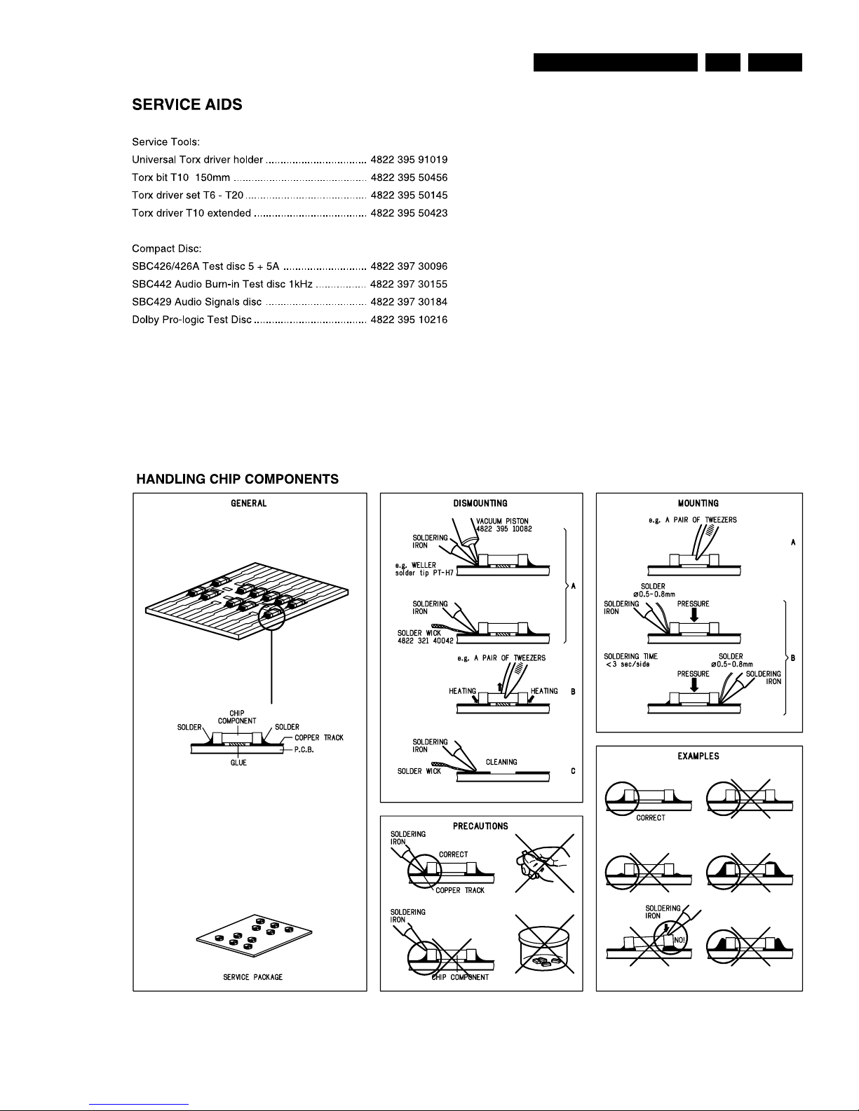
2.1 Lead Free Requirements
Pb(Lead) Free Solder
When soldering , be sure to use the pb free solder.
INDENTIFICATION:
Regardless of special logo (not always indicated)
one must treat all sets from
1 Jan 2005
onwards, according next
rules:
Important note: In fact also products of year 2004 must be treated in
this way as long as you avoid mixing solder-alloys (leaded/ lead-free).
So best to always use SAC305 and the higher temperatures belong
to this.
Due to lead-free technology some rules have to be respected by the
workshop during a repair:
Use only lead-free solder alloy Philips SAC305 with order
code 0622 149 00106. If lead-free solder-paste is required,
please contact the manufacturer of your solder-equipment.
In general use of solder-paste within workshops should be
avoided because paste is not easy to store and to handle.
Use only adequate solder tools applicable for lead-free solder
alloy. The solder tool must be able
o To reach at least a solder-temperature of 400°C,
o To stabilize the adjusted temperature at the solder-tip
o To exchange solder-tips for different applications.
Adjust your solder tool so that a temperature around 360°C
time of the solder-joint should not exceed ~ 4 sec. Avoid
temperatures above 400°C otherwise wear-out of tips will rise
drastically and
ux-
uid will be destroyed. To avoid wear-out
of tips switch off un-used equipment, or reduce heat.
Mix of lead-free solder alloy / parts with leaded solder alloy /
parts is possible but PHILIPS recommends strongly to avoid
mixed solder alloy types (leaded and lead-free).
If one cannot avoid or does not know whether product is leadfree, clean carefully the solder-joint from old solder alloy and
re-solder with new solder alloy (SAC305).
Use only original spare-parts listed in the Service-Manuals.
Not listed standard-material (commodities) has to be
purchased at external companies.
Special information for BGA-ICs:
- always use the 12nc-recognizable soldering temperature
pro
le of the speci
c BGA (for de-soldering always use the
lead-free temperature pro
le, in case of doubt)
the IC against moisture. After opening, dependent of MSLlevel seen on indicator-label in the bag, the BGA-IC possibly
still has to be baked dry. (MSL=Moisture Sensitivity Level).
This will be communicated via AYS-website.
Do not re-use BGAs at all.
For sets produced before 1.1.2005 (except products of 2004),
containing leaded solder-alloy and components, all needed
spare-parts will be available till the end of the service-period.
For repair of such sets nothing changes.
On our website
you
nd
more information to:
BGA-de-/soldering (+ baking instructions)
Heating-pro
les of BGAs and other ICs used in
Philips-sets
You will
nd this and more technical information within the
For additional questions please contact your local repair-helpdesk.
EN 8
3139 785 31470
3
Directions For Use
3. Directions For Use
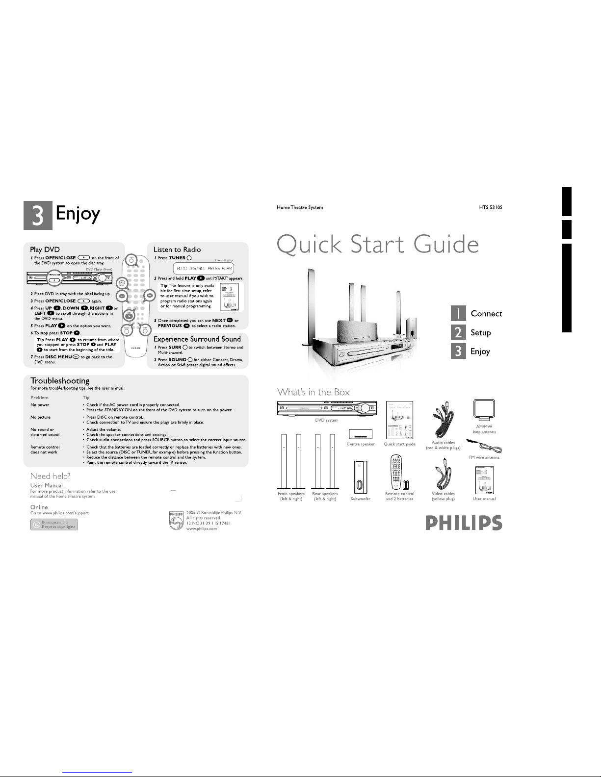
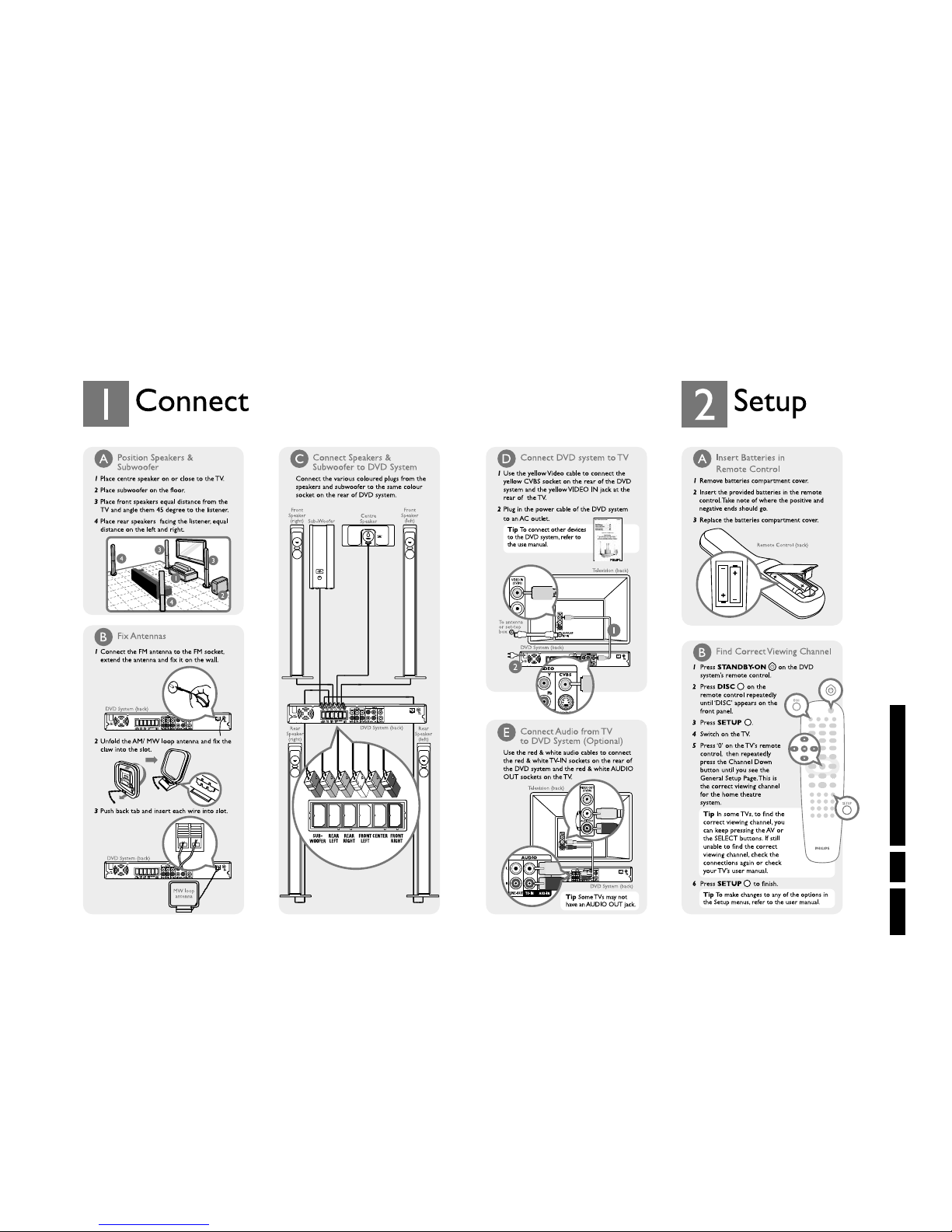
The following except of the Quick Use Guide serves as an introduction to the set.
The Complete Direction for the Use can be downloaded in different languages from the internet site of Philips Customer care Cen
ter:
www.p4c.philips.com
EN 9
3139 785 31470
Directions For Use
3
EN 10
3139 785 31470
4
Dismantling Instructions & Service Positions
B B B
Figure 4-3
A
D
Figure 4-4
C
E
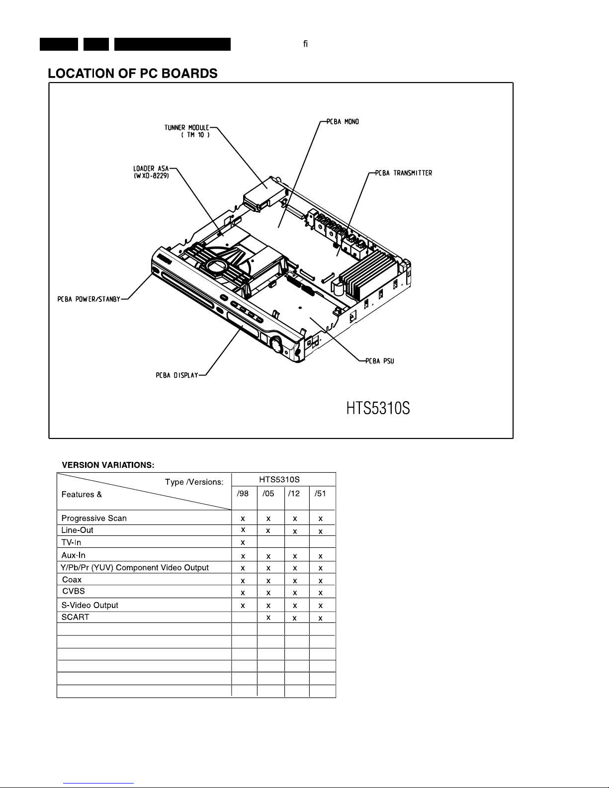
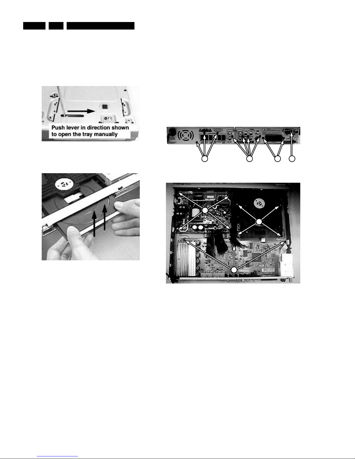
4.2 Dismantling of the Tuner Module,
MONO Board, Front Board, PSU Module
1) Loosen 1 screw A (see Figure 4-3) to remove the Tuner
Module (pos 1040).
2) Loosen 9 screws B (see Figure 4-3) and 4 screws
(see Figure 4-4) to remove MONO Board.
3) Release 4 snap hooks to remove Front Board.
- 1 snap hook each on the left & right side (pos 161).
- 2 snap hooks on the bottom side (pos 161).
4) Loosen 4 screws E (see Figure 4-4) to remove the
PSU Module.
4. Dismantling Instructions
4.1 Dismantling of the DVD Loader
1) The tray can be manually open by inserting a minus
screw drive and push the lever in the direction as shown
in Figure 3-1 to unlock the tray before sliding it out.
Figure 4-1
2) Slide out the tray and remove the Cover Tray (pos 110)
as shown in Figure 4-2.
Figure 4-2
3) Loosen 5 screws to remove the Front Top.(pos 240)
- 1 screw each on the left & right side (pos 272)
- 3 screws behind
4) Loosen 4 screws C (see Figure 4-4) to remove the DVD
Loader.
 Loading...