

Philips HTS5120/12, HTS5120/51, HTS5120/55, HTS5120/78, HTS5120/93 Service Manual
...
Published by KC-KM 1030 AVM Printed in he Netherlands
HTS5120/12/51/55/78/93/98
Subject to modification EN 3139 785 35241
Home Theater System
CLASS 1
LASER PRODUCT
Contents
Page
Contents
Page
©
Copyright 2010 Philips Consumer Electronics B.V. Eindhoven, The Netherlands.
All rights reserved. No part of this publication may be reproduced, stored in a
retrieval system or transmitted, in any form or by any means, electronic,
mechanical, photocopying, or otherwise without the prior permission of Philips.
Version 1.1
2 Technical Specification and Connection Facilities
3 Laser Beam Safety Precautions..................................3-1
1 Repair Scenario Matrix ...............................................1-1
4 Important Safety Precautions ......................... 4-1 to 4-2
5 Safety Check After Servicing .................................... 5-1
7 Standard Notes For Servicing .................................. .7-1
8 Special Information BGA IC & Flat Pack-IC
6 Safety Information General Notes & Lead Free
9 Direction of Use ...............................................9-1 to 9-5
10 Cabinet Disassembly Instructions ................... 10-1 to 10-2
16 Main Unit--Touch Button Board
11 Troubleshooting ..................................................... 11-1
12 Software Upgrading Procedure ............................. 12-1
13 Software Version Check ........................................ 12-2
14 Block Diagram ........................................................13-1
15 Wiring Diagram ...................................................... 14-1
17 Main Unit--VFD Display Board
PT6311 IC Specification ................... 15-4
18 Main Unit-- IPOD,USB & MP3 Board
Layout Diagram ................................ 15-6
19 Main Unit--Decoder Board Circuit Diagram
20 Main Unit--AMP Board
24 Main Unit Exploded View ............................................ 16-1
25 Subwoofer Exploded View ...........................................16-2
26 Packing Exploded View ...............................................16-3
27 Revision List ................................................................17-1
21 Main Unit--Radio Transmit Board
................................................... 8-1 to 8-3
Circuit Diagram ...................... 15-7 to 15-10
Circuit Diagram .................................. 15-18
Circuit Diagram ...................... 15-20 to 15-22
Circuit Diagram ..................... 15-25 to 15-27
Circuit Diagram ...................... 15-12 to 15-15
Layout Diagram ................................ 15-17
Layout Diagram ................................. 15-19
Layout Diagram ................................. 15-24
Layout Diagram ................................. 15-28
Circuit Diagram ..................... 15-29 to 15-30
Layout Diagram ................................. 15-32
EN29LV320A IC Specification ..........15-11
TDA8920 IC Specification ................ 15-31
UDA1355H IC Specification ............ 15-16
CC2400 IC Specification .................. 15-23
WT5700 IC Specification ................. 15-2
22 Subwoofer--Radio Receiver Board
23 Subwoofer--Power Board
.................................................. 2-1 to 2-3
Circuit Diagram ................................. 15-1
Layout Diagram ................................ 15-1
Circuit Diagram ................................. 15-3
Circuit Diagram ................................. 15-6
Layout Diagram ................................ 15-5
Requirement ............................ 6-1 to 6-2
Features
RDS
Voltage Selector
ECO Standby
DTS
Feature
Different
/12
/51 /55 /78
/93 /98
Repair Scenario Matrix
Type versions
Boards in used /12 /51 /55 /78 /93 /98
Touch Button Board C C C C C C
VFD Display Board C C C C C C
IPOD, USB & MP3 Boards C C C C C C
Up/Down Control Board C C C C C C
Left/Right Control Board C C C C C C
Optical Socket Board C C C C C C
Decoder Board BD BD BD BD BD BD
AMP Board BD BD BD BD BD BD
Radio Transmit Board BD BD BD BD BD BD
Frequency Divider Board BD BD BD BD BD BD
Radio Receiver Board BD BD BD BD BD BD
Power Board BD BD BD BD BD BD
* BD = Board Level Replacem
* C = Component Level Repair
HTS5120
Main Unit:
Subwoofer Box:
1-1

1.1 PCB Locations
1.2 General:
Power supply : 100-240V, 50Hz~60Hz
Power consumption(Main Unit) : 35W
Power consumption(Subwoofer) : 45W
Amplifer : 70W(8Ω) x 2 + 260W(8Ω)
Standby power consumption : < 1 W
1.3 Radio
1.4 Analog Inputs / Outputs
Tuning Frequency Range : 87.5MHz - 108MHz
1.4.1 Audio Input Connectors
1.4.2 Video Output Connectors
S/N (video unweighted) at 75Ω : ≤71dB
Singal To Noise Ratio : ≥50dB
(Typical 3 minutes)
Search Tuning Sensitivity : 19~35 dBf
Search Time Digital Tuning System
Maximun tuning error of a recalled
program : ± 22.5 kHz
Maximun tuning error during
operation(drift) : ≤ 50 kHz
Stop level (vision carrier) : ≥ 31dBμV
RF Signal : < 2.5min
Modulation : 1kHz
Noise Limlited sensitivity
(26dB Mono) : 22 dBf
Noise Limlited sensitivity
(46dB Stereo) : 52dBf
Image Rejection Ratio : ≥25dB
Input voltage : 2Vrms max
Input impledance : >10kΩ
Overall Frequency Response : 63Hz~12.5kHz ±3dB
AUDION IN (AUDIO 1/2) -- AUX IN
VIDEO OUT -- CVBS OUT
Input voltage : 1Vrms max
Input impledance : >10kΩ
Output voltage : 700mVpp+10/-15%
Output impledance : 75Ω
S/N on output : ≥ 55dB
AUDION IN (AUDIO 1/2) -- MP3 LINE IN
50dB S/N Sensitivity (Mono),
freq. deviation 75kHz(L,M,H) : ≤23dBf
Decoder Board
Optical Socket
Board
VFD Display
Board
2-1
Radio Transmit Board
Technical Specification and Connection Facilities
1. Technical Specification and Connection Facilities
Radio Receiver Board
Power Board
Power Control Switch
110/220V(for 55/98
version)
Technical Specifications and Connection Facilities
VIDEO OUT -- (Y/Pb/Pr)
Output voltage : 700mVpp+10/-15%
iPod/ iPhone Voltage : 4.9V ~ 5.02V/1A
Output impedance : 75Ω
S/N on outputs : ≥55dB
1.5 Digital Inputs/Outputs
1.6 Ipod Docking Component
1.7.3 Video Supporting Format
Signal System : PAL / NTSC
480i/576i, 480p/576p, 720p, 1080i
480p, 576p, 720p, 1080i, 1080p
HDMI Output:
Component Video Output:
1.5.1 COAXIAL DIGITAL IN
LPCM : according IEC 60958-3
MPEG 1, MPEG 2, AC3 : according IEC 61937
DTS : according IEC 61937 +
addendum
1.5.2 USB
Compatibility : USB 2.0
Storage Class)
Type of connector
Class support : UMS(USB Mass
File System : FAT12, FAT24, FAT36
: Series A Connector
1.5.3 HDMI Output
1.5.4 Sampling Frequency:
Compatibility
MP3 : 22kHz, 44.1kHz, 48kHz
WMA : 44.1kHz, 48kHz
1.5.4 Canstant bit rate:
PHILIPS specified using iPod/iPhone
MP3 : 112 kbps - 320 kbps
WMA : 44 kbps - 192 kbps
: HDMI version 1.3
Type of connector : Type A connector
(19 pins)
1.7 Video Performance
1.7.1 SNR
PAL
RGB CVBS
≥ 55 dB Lumincance: ≥ 55 dB
Chroma: ≥ 55 dB (AM)
≥ 52 dB (PM)
NTSC
Y Pb Pr CVBS
≥ 55 dB Lumincance: ≥ 55 dB
Chroma: ≥ 54 dB (AM)
≥ 54 dB (PM)
1.7.2 Bandwidth
PAL
RGB CVBS
0.5 to 4 MHz:+1dB/
-2dB
0.5 to 4 MHz:+1dB/
-2dB
4.8 MHz:-3dB 4.8 MHz:-3dB
5.8 MHz:-6dB 5.8 MHz:-6dB
NTSC
YPbPr CVBS
4.2 MHz:-3dB 4.2 MHz:-3dB
5.8 MHz:-6dB 5.8 MHz:-6dB
With Pscan:
8.4MHz -3dB
2-2
Technical Specifications and Connection Facilities
1.8 Dimension and Weight
Set Dimension W x H x D : 790.6 x 145 x 57.4 mm
Net Weight : 2.23 kg
Subwoofer Dimension W x H x D : 182 x 365 x 306 mm
Net Weight : 6 kg
1.9 Laser Output Power & Wavelength
1.9.1 DVD
Output power during reading : 7mW
Output power during writing : 6mW
Wavelength : 80nm (at 25 °C)
1.9.2 CD
Output power : 6mW
Wavelength : 60nm (at 25 °C)
2.0 Playability
Video Playback
1. Playback Media:
CD-R/CD-RW, DVD+R/+RW,
DVD-R/-RW, DVD-Video, Video
CD/SVCD, DVD+R DL, DVD-R
DL, USB flash drive
x
2. Compression Formats:
MPEG2, MPEG1, DivX 3.11, DivX
4.x, DivX 5.x, DivX 6.0, MPEG4
x
Audio Playback
1. Playback Media:
Audio CD, CD-R/RW, DVD+R DL,
DVD+R/+RW, DVD-R/-RW, MP3-
CD, MP3-DVD, USB flash drive,
WMA-CD
x
2. Compression Format:
Dolby Digital, MP3, MPEG2
Multichannel, PCM, WMA
x
3. MPEG1 bit rates: 64-384 kbps
and VBR
x
Still Picture Playback
1. Playback Media: CD-R/RW,
DVD+R DL, DVD+R/+RW, DVDR/-RW, Picture CD, USB Digital
Camera (PTP), USB flash drive
x
2. Picture Compression Format:
JPEG, JPEG digital camera
photos
x
3. Picture enhancement: Slideshow
with MP3 playback, Create
albums, Rotate, Slideshow with
music playback, Zoom
x
2-3
Laser Beam Safety Precautions
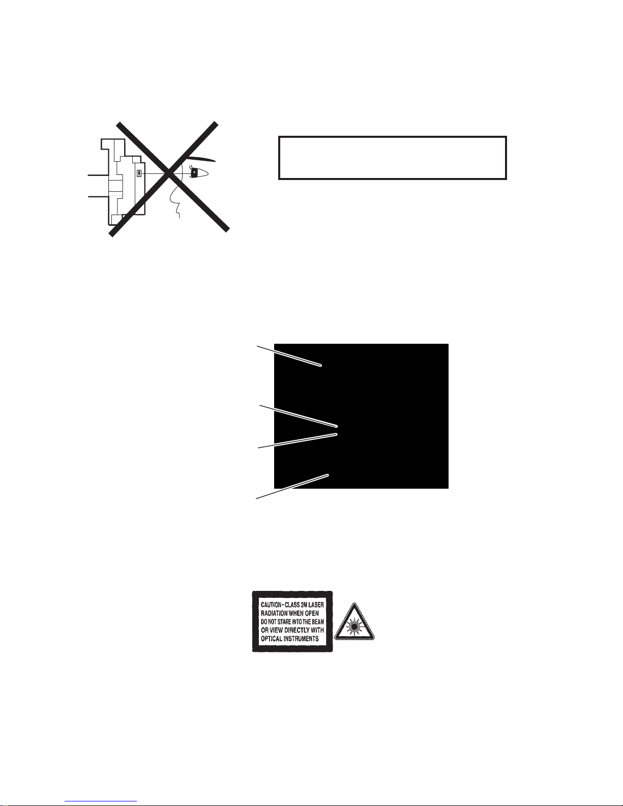
This DVD player uses a pickup that emits a laser beam.
The laser beam is emitted from the location shown in the figure. When checking the laser diode, be sure to keep
your eyes at least 30 cm away from the pickup lens when the diode is turned on. Do not look directly at the laser
beam.
CAUTION: Use of controls and adjustments, or doing procedures other than those specified herein, may result in
hazardous radiation exposure.
Location: Inside Top of DVD mechanism.
Do not look directly at the laser beam coming
from the pickup or allow it to strike against your
skin.
Drive Mechanism Assembly
Laser Beam Radiation
Laser Pickup
Turntable
3-1

Electronics N.V. bears no responsibility
for improper wall mounting that results in
accident, injury or damage.
For speakers with stands, use only the
supplied stands. Secure the stands to
the speakers tightly. Place the assembled
stands on flat, level surfaces that can
support the combined weight of the
speaker and stand.
Never place the product or any objects
on power cords or on other electrical
equipment.
If the product is transported in
temperatures below 5°C, unpack the
product and wait u
ntil
its temperature
matches room temperature before
connecting it to the power outlet.
Visible and invisible laser radiation when
open. Avoid exposure to beam.
Do not touch the disc optical lens inside
the disc compartment.
Risk of overheating!
Never install this product in a confined
space. Always leave a space of at least
four inches around the product for
ventilation. Ensure curtains or other
objects never cover the ventilation slots
on the product.
Risk of contamination!
Do not mix batteries (old and new or
carbon and alkaline,
etc.).
Remove
batteries if they are exhausted
or if the remote control is not to be used
for a long time.
Batteries contain chemical substances,
they should be disposed of properly.
Product care
Do not insert any objects other than discs
into the disc compartment.
Do not insert warped or cracked discs
into the disc compartment.
Remove discs from the disc compartment
if you are not using the product for an
extended period of time.
•
•
•
•
•
•
•
•
•
•
•
•
Only use microfiber cloth to clean the
product.
•
Important
Important Safety Precautions
Read and understand all instructions before you use
your home theater. If damage is caused by failure to
follow instructions, the warranty does not apply.
Safety
Risk of electric shock or fire!
Never expose the product and
accessories to rain or water. Never place
liquid containers, such as vases, near the
product. If liquids are spilt on or into the
product, disconnect it from the power
outlet immediately. Contact Philips
Consumer Care to have the product
checked before use.
Never place the product and accessories
near naked flames or other heat sources,
including direct sunlight.
Never insert objects into the ventilation
slots
or
other openings on the product.
Where the mains plug or an appliance
coupler is used as the disconnect device,
the disconnect device shall remain readily
operable.
Disconnect the product from the power
outlet before lightning storms.
When you disconnect the power cord,
always pull the plug, never the cable.
Risk of short circuit or fire!
Before you connect the product to the
power outlet, ensure that the power
voltage matches the value printed on the
back or bottom of the product. Never
connec
t the
product to the power outlet
if the voltage is different.
Risk of injury or damage to the home theater!
For wall-mountable products, use only
the supplied wall mount bracket. Secure
the wall mount to a wall that can support
the combined weight of the product
and the wall mount. Koninklijke Philips
•
•
•
•
•
•
•
•
4-1

User manual CD
To read the complete user manual, which
includes information on advanced features, use
the CD supplied with your home theater. For
a printed copy of the complete user manual,
contact Philips Consumer Care in your country.
To access the user manual
Caution
The user manual CD is for PC or Mac only. Do
not insert the user manual CD into the disc
compartment of the home theater.
•
Requirements:
A PC (Microsoft Windows
compatible) or Mac (OS X) with
CD-ROM
Adobe Reader
1 Insert the user manual CD into the CD-
ROM tray of the PC or Mac.
2 Close the CD-ROM tray.
The user manual screen appears. If the
user manual screen does not appear,
skip Step 3 and navigate to the ‘pdf’
folder in the CD-ROM, double-clicking
the PDF of your choice.
3 Click a user manual language.
Acrobat Reader launches, displaying
the complete user manual in the
language of your choice.
•
•
»
»
Disposal of your old product and
batteries
Your product is designed and manufactured
with high quality materials and components,
which can be recycled and reused.
When this crossed-out wheeled bin symbol
is attached to a product it means that the
product is covered by the European Directive
2002/96/EC. Please inform yourself about the
local separate collection system for electrical
and electronic products.
Please act according to your local rules and
do not dispose of your old products with your
normal household waste.
Corr
ect
disposal of your old product helps to
prevent potential negative consequences for
the environment and human health.
Your product contains batteries covered by
the European Directive 2006/66/EC, which
cannot be disposed with normal household
waste.
Please inform yourself about the local rules
on separate collection of batteries because
correct disposal helps to prevent negative
consequences for the environmental and
human health.
Important Safety Precautions
4-2
5-1
Safety Check after Servicing
Examine the area surrounding the repaired location for damage or deterioration. Observe that screws, parts, and
wires have been returned to their original positions. Afterwards, do the following tests and confirm the specified
values to verify compliance with safety standards.
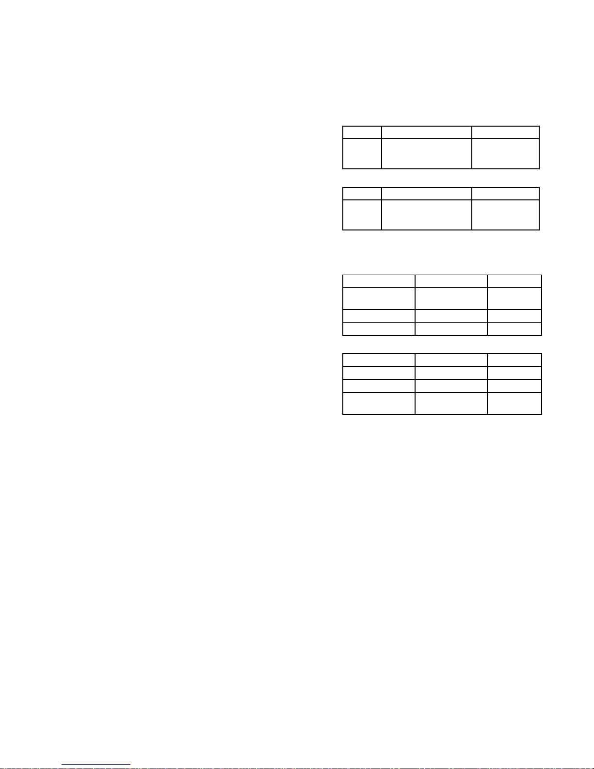
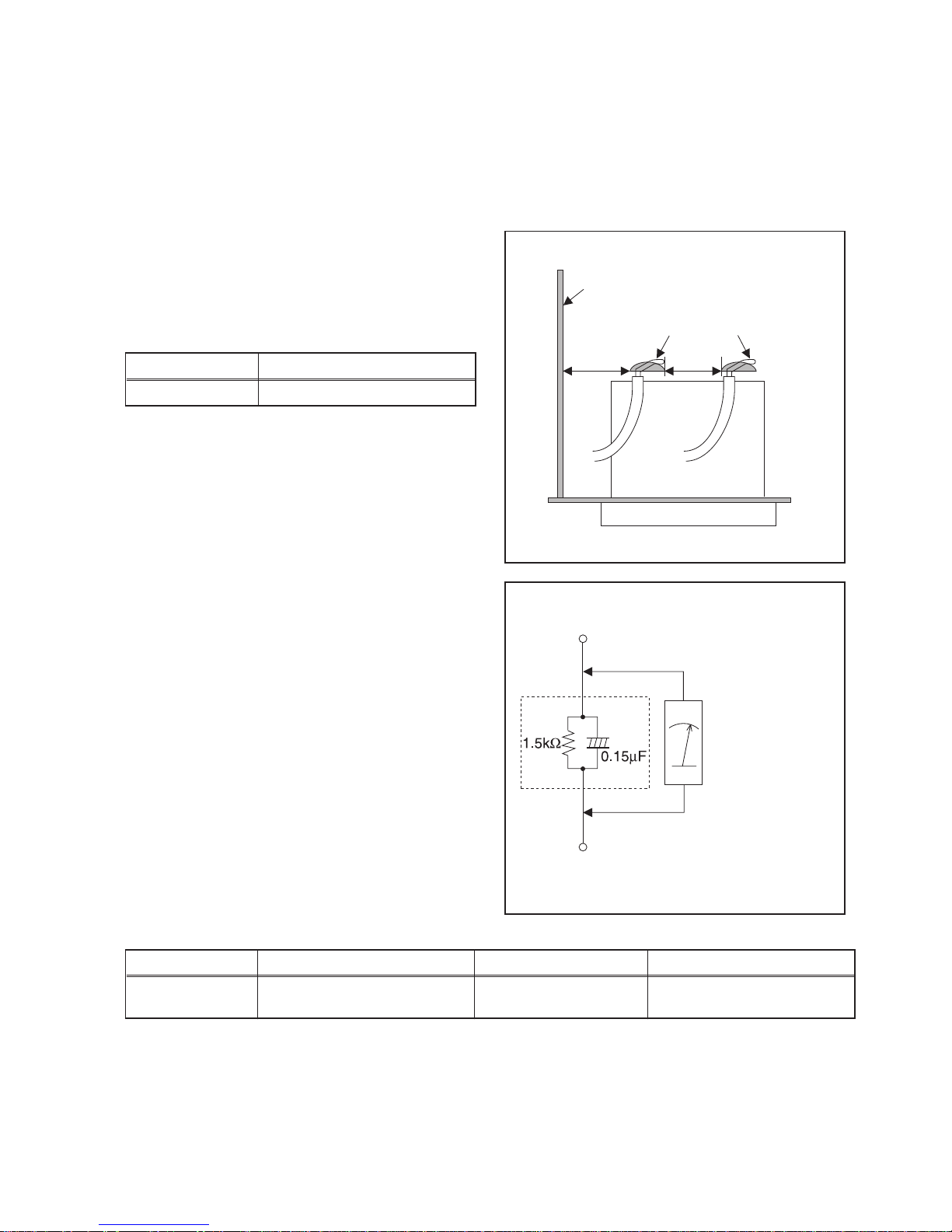
1. Clearance Distance
When replacing primary circuit components, confirm
specified clearance distance (d) and (d’) between
soldered terminals, and between terminals
and
surrounding metallic parts. (See Fig. 1)
Table 1: Ratings for selected area
Note: This table is unofficial and for reference only. Be
sure to confirm the precise values.
2. Leakage Current Test
Confirm the specified (or lower) leakage current
between B (earth ground, power cord plug prongs) and
externally exposed accessible parts (RF terminals,
antenna terminals, video and audio input and output
terminals, microphone jacks, earphone jacks, etc.) is
lower
than
or equal to the specified value in the table
below.
Measuring Method (Power ON):
Insert load Z between B (earth ground, power cord plug
prongs) and exposed accessible parts. Use an AC
voltmeter to measure across the terminals of load Z.
See Fig. 2 and the following table.
Table 2: Leakage current ratings for selected areas
Note: This table is unofficial and for reference only. Be sure to confirm the precise values.
AC Line Voltage Clearance Distance (d), (d
’)
11
0V~220V ≥ 3.2 mm (0.126 inches)
AC Line Voltage Load Z Leakage Current (i) Earth Ground (B) to:
110V~220V
0.15 µF CAP. & 1.5 kΩ RES.
Connected in parallel
i ≤ 0.5 mA Peak Exposed accessible parts
Chassis or Secondary Conductor
Primary Circuit
Fig. 1
d' d
AC Voltmeter
(High Impedance)
Exposed Accessible Part
B
Earth Ground
Power Cord Plug Prongs
Z
Fig. 2
1 Safety Instructions
1.1 General Safety
Safety regulations require that during a repair:
• Connect the unit to the mains via an isolation transformer.
• Replace safety components, indicated by the symbol
,
only by components identical to the original ones. Any
other component substitution (other than original type)
may increase risk of fire or electrical shock hazard.
Safety regulations require that after a repair, you must return
the unit in its original condition. Pay, in particular, attention to
the following points:
• Route the wires/cables correctly, and fix them with the
mounted cable clamps.
• Check the insulation of the mains lead for external
damage.
• Check the electrical DC resistance between the mains
plug and the secondary side:
1. Unplug the mains cord, and connect a wire between
the two pins of the mains plug.
2. Set the mains switch to the ‘on’ position (keep the
mains cord unplugged!).
3. Measure the resistance value between the mains
plug and the front panel, controls, and chassis
bottom.
4. Repair or correct unit when the resistance
measurement is less than 1 MΩ.
5. Verify this, before you return the unit to the customer/
user (ref. UL-standard no. 1492).
6. Switch the unit ‘off’, and remove the wire between the
two pins of the mains plug.
1.2 Laser Safety
This unit employs a laser. Only qualified service personnel
may remove the cover, or attempt to service this device (due
to possible eye injury).
Laser Device Unit
resal rotcudnocimeS : epyT
sAlAaG
Wavelength : 650 nm (DVD)
)DC/DCV( mn 087 :
Output Power : 20 mW
)gnitirw WR+DVD(
Wm 8.0 :
)gnidaer DVD(
Wm 3.0 :
)gnidaer DC/DCV(
Beam divergence : 60 degree
CLASS 1
LASER PRODUCT
1-2 erugiF
Note: Use of controls or adjustments or performance of
procedure other than those specified herein, may result in
hazardous radiation exposure. Avoid direct exposure to beam.
2 Warnings
2.1 General
• All ICs and many other semiconductors are susceptible to
electrostatic discharges (ESD,
). Careless handling
during repair can reduce life drastically. Make sure that,
during repair, you are at the same potential as the mass
of the set by a wristband with resistance. Keep
components and tools at this same potential.
Available ESD protection equipment:
– Complete kit ESD3 (small tablemat, wristband,
connection box, extension cable and earth cable)
4822 310 10671.
– Wristband tester 4822 344 13999.
• Be careful during measurements in the live voltage
section. The primary side of the power supply, including
the heatsink, carries live mains voltage when you
connect the player to the mains (even when the
player is ‘off’!). It is possible to touch copper tracks and/
or components in this unshielded primary area, when
you service the player. Service personnel must take
precautions to prevent touching this area or components
in this area. A ‘lightning stroke’ and a stripe-marked
printing on the printed wiring board, indicate the primary
side of the power supply.
• Never replace modules, or components, while the unit is
‘on’.
2.2 Laser
• The use of optical instruments with this product, will
increase eye hazard.
• Only qualified service personnel may remove the cover or
attempt to service this device, due to possible eye injury.
• Repair handling should take place as much as possible
with a disc loaded inside the player.
• Text below is placed inside the unit, on the laser cover
shield:
Figure 2-2
Safety Information, General Notes & Lead Free Requirements
CAUTION VISIBLE AND INVISIBLE LASER RADIATION WHEN OPEN AVOID EXPOSURE TO BEAM
ADVARSEL SYNLIG OG USYNLIG LASERSTRÅLING VED ÅBNING UNDGÅ UDSÆTTELSE FOR STRÅLING
ADVARSEL SYNLIG OG USYNLIG LASERSTRÅLING NÅR DEKSEL ÅPNES UNNGÅ EKSPONERING FOR STRÅLEN
VARNING SYNLIG OCH OSYNLIG LASERSTRÅLNING NÄR DENNA DEL ÄR ÖPPNAD BETRAKTA EJ STRÅLEN
VARO! AVATTAESSA OLET ALTTIINA NÄKYVÄLLE JA NÄKYMÄTTÖMÄLLE LASER SÄTEILYLLE ÄLÄ KATSO SÄTEESEEN
VORSICHT SICHTBARE UND UNSICHTBARE LASERSTRAHLUNG WENN ABDECKUNG GEÖFFNET NICHT DEM STRAHL AUSSETSEN
DANGER VISIBLE AND INVISIBLE LASER RADIATION WHEN OPEN AVOID DIRECT EXPOSURE TO BEAM
ATTENTION RAYONNEMENT LASER VISIBLE ET INVISIBLE EN CAS D’OUVERTURE EXPOSITION DANGEREUSE AU FAISCEAU
6-1

Safety Information, General Notes & Lead Free Requirements
3 Lead Free Requirement
Information about Lead-free produced sets
Philips CE is starting production of lead-free sets from
1.1.2005 onwards.
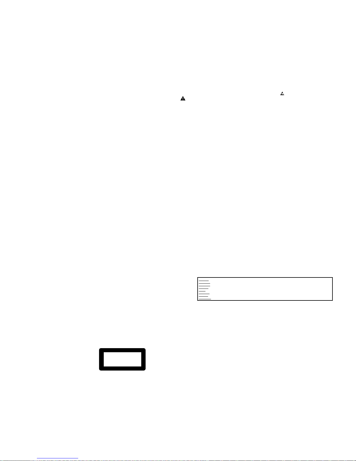
INDENTIFICATION:
Regardless of special logo (not always indicated)
One must treat all sets from 1 Jan 2005 onwards, according
next rules.
Example S/N:
Bottom line of typeplate gives a 14-digit S/N. Digit 5&6 is the year, digit 7&8 is
the week number, so in this case 1991 wk 18
So from 0501 onwards = from 1 Jan 2005 onwards
Important note: In fact also products of year 2004 must be treated in this way as long as you
avoid mixing solder-alloys (leaded/ lead-free). So best to always use SAC305 and the higher
temperatures belong to this.
Due to lead-free technology some rules have to be respected by the
workshop during a repair:
Use only lead-free solder alloy Philips SAC305 with
order code 0622 149 00106. If lead-free solder-pate
is required, please contact the manufacturer of your
solder-equipment. In general use of solder-paste within
workshops should be avoided because paste is not easy
to store and to handle.
Use only adequate solder tools applicable for lead-free
solder alloy. The solder tool must be able
o To reach at least a solder-temperature of 400°C,
o To stabilize the adjusted temperature at the solder-
tip
o To exchange solder-tips for different applications.
Adjust your solder tool so that a temperature around
360°C – 380°C is reached and stabilized at the solder
joint. Heating-time of the solder-joint should not exceed
~ 4 sec. Avoid temperatures above 400°C otherwise
wear-out of tips will rise drastically and flux-fluid will be
destroyed. To avoid wear-out of tips switch off un-used
equipment, or reduce heat.
Mix of lead-free solder alloy / parts with leaded solder
alloy / parts is possible but PHILIPS recommends strongly
to avoid mixed solder alloy types (leaded and lead-free).
If one cannot avoid or does not know whether product is
lead-free, clean carefully the solder-joint from old solder
alloy and re-solder with new solder alloy (SAC305).
Use only original spare-parts listed in the ServiceManuals. Not listed standard-material (commodities) has
to be purchased at external companies.
Special information for BGA-ICs:
- always use the 12nc-recognizable soldering temperature
profile of the specific BGA (for de-soldering always use
the lead-free temperature profile, in case of doubt)
- lead free BGA-ICs will be delivered in so-called ‘drypackaging’ (sealed pack including a silica gel pack) to
protect the IC against moisture. After opening, dependent
of MSL-level seen on indicator-label in the bag, the
BGA-IC possibly still has to be baked dry. (MSL=Moisture
Sensitivity Level). This will be communicated via AYSwebsite.
Do not re-use BGAs at all.
For sets produced before 1.1.2005 (except products of
2004), containing leaded solder-alloy and components,
all needed spare-parts will be available till the end of the
service-period. For repair of such sets nothing changes.
On our website www.atyourservice.ce.Philips. com
you find more information to:
BGA-de-/soldering (+ baking instructions)
Heating-profiles of BGAs and other ICs used in Philips-
sets
You will find this and more technical information within
the “magazine”, chapter “workshop news”.
For additional questions please contact your local repair-helpdesk.
6-2
7-1
Standard Notes for Servicing
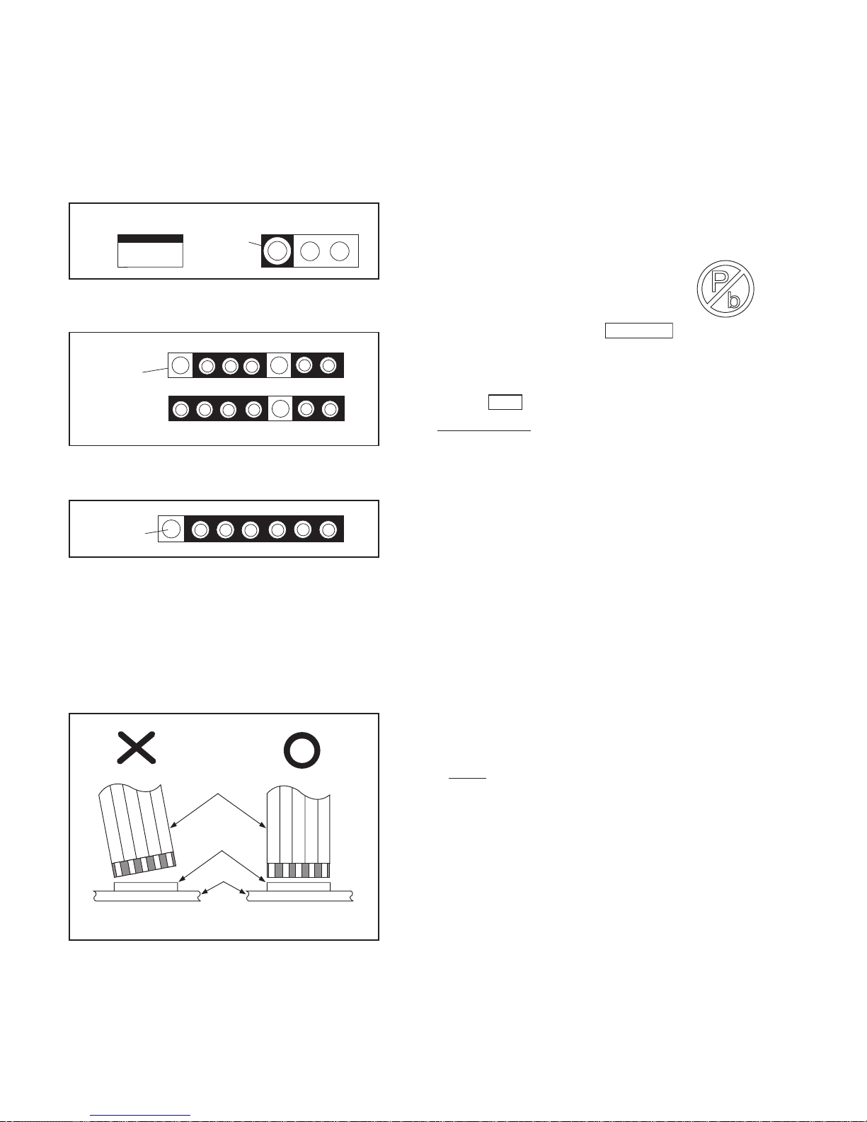
Circuit Board Indications
1. The output pin of the 3 pin Regulator ICs is
indicated as shown.
2. For other ICs, pin 1 and every fifth pin are
indicated as shown.
3. The 1st pin of every male connector is indicated as
shown.
Instructions for Connectors
1. When you connect or disconnect the FFC (Flexible
Foil Connector) cable, be sure to first disconnect
the AC cord.
2. FFC (Flexible Foil Connector) cable should be
inserted parallel into the connector, not at an
angle.
Pb (Lead) Free Solder
When soldering, be sure to use the Pb free solder.
Information about lead-free soldering
Philips CE is producing lead-free sets from 1.1.2005
onwards.
IDENTIFICATION
Regardless of special logo (not always
indicated)
One must treat all sets from
onwards, according to the next rule:
Serial Number gives a 14-digit. Digit 5&6 shows the
YEAR, and digit 7&8 shows the WEEK.
So from onwards=from 1 Jan 2005 onwards
Important note : In fact also products of year 2004
must be treated in this way as long as you avoid
mixing solder-alloys (leaded/ lead-free). So best to
always use SAC305 and the higher temperatures
belong to this.
Due to lead-free technology some rules have to be
respected by the workshop during a repair:
• Use only lead-free solder alloy Philips SAC305 with
order code 0622 149 00106. If lead-free solderpaste is required, please contact the manufacturer
of your sol
der-equ
ipment. In general use of solderpaste within workshops should be avoided because
paste is not easy to store and to handle.
• Use only adequate solder tools applicable for leadfree solder alloy. The solder tool must be able
• To reach at least a solder-temperature of 400°C,
• To stabilize the adjusted temperature at the solder-
tip
• To exchange solder-tips for different applications.
• Adjust your solder tool so that a temperature around
360°C
- 380°C is reached and stabilized at the
solder joint. Heating-time of the solder-joint should
not exceed ~ 4 sec. Avoid temperatures above
400°C otherwise wear-out of tips will rise drastically
and flux-fluid will be destroyed. To avoid wear-out of
tips switch off un-used equipment, or reduce heat.
• Mix of lead-free solder alloy / parts with leaded
solder alloy / parts is possible but PHILIPS
recommends strongly to avoid mixed solder alloy
types (leaded
and
lead-free).
If one cannot avoid or does not know whether
product is lead-free, clean carefully the solder-joint
from old solder alloy and re-solder with new solder
alloy (SAC305).
• Use only original spare-parts listed in the ServiceManuals. Not listed standard-material (commodities)
has to be purchased at external companies.
Top View
Out
In
Bottom View
Input
5
10
Pin 1
Pin 1
FFC Cable
Connector
CBA
* Be careful to avoid a short circuit.
1 Jan 2005
0501
8-1
•
Special information for BGA-ICs:
- always use the 12nc-recognizable soldering
temperature profile of the specific BGA (for desoldering always use the lead-free temperature
profile, in case of doubt)
- lead free BGA-ICs will be delivered in so-called
'dry-packaging' (sealed pack including a silica gel
pack) to protect the IC against moisture. After
opening, dependent of MSL-level seen on indicatorlabel in the bag, the BGA-IC possibly still has to be
baked dry. (MSL=Moisture Sensit
ivit
y Level). This
will be communicated via AYS-website.
Do not re-use BGAs at all.
• For sets produced before 1.1.2005 (except products
of 2004), containing leaded solder-alloy and
components, all needed spare-parts will be available
till the end of the service-period. For repair of such
sets nothing changes.
• On our website
www.atyourservice.ce.Philips.com
you find more
information to:
• BGA-de-/soldering (+ baking instructions)
• Heating-profiles of BGAs and other ICs used in
Philips-sets
You will find this and more technical information within
the “magazine”, chapter “workshop news”.
For additional questions please contact your local
repair-helpdesk.
How to Remove / Install Flat Pack-IC
Special Information of BGA IC & Flat Pack-IC
1. Removal
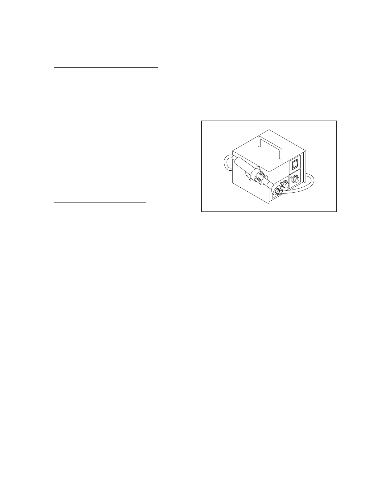
With Hot-Air Flat Pack-IC Desoldering Machine:
1. Prepare the hot-air flat pack-IC desoldering
machine, then
apply hot air to the Flat Pack-IC
(about 5 to 6 seconds). (Fig. S-1-1)
2. Remove the flat pack-IC with tweezers while
applying the hot air.
3. Bottom of the flat pack-IC is fixed with glue to the
CBA; when removing entire flat pack-IC, first apply
soldering iron to center of the flat pack-IC and heat
up. Then remove (glue will be melted). (Fig. S-1-6)
4. Release the flat pack-IC from the CBA using
tweezers. (Fig. S-1-6)
CAUTION:
1. The Flat Pack-IC shape may differ by mo
dels.
Use
an appropriate hot-air flat pack-IC desoldering
machine, whose shape matches that of the Flat
Pack-IC.
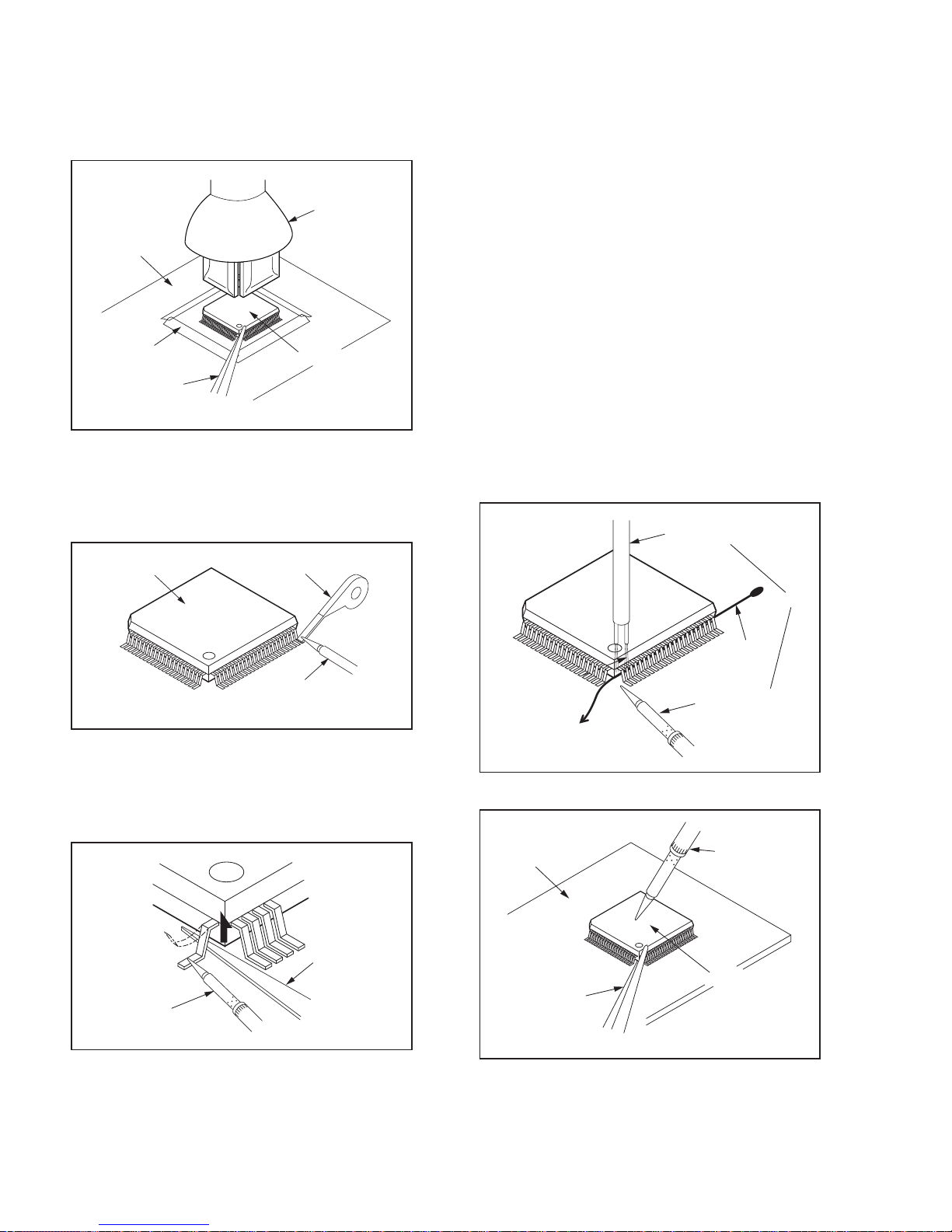
2. Do not supply hot air to the chip parts around the
flat pack-IC for over 6 seconds because damage
to the chip parts may occur. Put masking tape
around the flat pack-IC to protect other parts from
damage. (Fig. S-1-2)
Fig. S-1-1
3. The flat pack-IC on the CBA is affixed with glue, so
be careful not to break or damage the foil of each
pin or the solder lands under the IC when
removing it.
With Soldering Iron:
1. Using desoldering braid, remove the solder from
all pins of the flat pack-IC. When you use solder
flux which is applied to all pins of the flat pack-IC,
you can remove it easily. (Fig. S-1-3)
2. Lift each lead of the flat pack-IC upward one by
one, using a sharp pin or wire to whic
h
solder will
not adhere (iron wire). When heating the pins, use
a fine tip soldering iron or a hot air desoldering
machine. (Fig. S-1-4)
3. Bottom of the flat pack-IC is fixed with glue to the
CBA; when removing entire flat pack-IC, first apply
soldering iron to center of the flat pack-IC and heat
up. Then remove (glue will be melted). (Fig. S-1-6)
4. Release the flat pack-IC from the CBA using
tweezers. (Fig. S-1-6)
With Iron Wire:
1. Using desoldering braid, remove
the solder from
al
l pins of the flat pack-IC. When you use solder
flux which is applied to all pins of the flat pack-IC,
you can remove it easily. (Fig. S-1-3)
2. Affix the wire to a workbench or solid mounting
point, as shown in Fig. S-1-5.
3. While heating the pins using a fine tip soldering
iron or hot air blower, pull up the wire as the solder
melts so as to lift the IC leads from the CBA
contact pads as shown in Fig. S-1-5.
4. Bottom of the
flat pa
ck-IC is fixed with glue to the
CBA; when removing entire flat pack-IC, first apply
soldering iron to center of the flat pack-IC and heat
up. Then remove (glue will be melted). (Fig. S-1-6)
5. Release the flat pack-IC from the CBA using
tweezers. (Fig. S-1-6)
Note: When using a soldering iron, care must be
taken to ensure that the flat pack-IC is not
being held by glue. When the flat pack-IC is
removed from the CBA, handle it gently
because it may be dama
ged
if force is applied.
Hot-air
Flat Pack-IC
Desoldering
Machine
CBA
Flat Pack-IC
Tweezers
Masking
Tape
Fig. S-1-2
Flat Pack-IC
Desoldering Braid
Soldering Iron
Fig. S-1-3
Fine Tip
Soldering Iron
Sharp
Pin
Fig. S-1-4
To Solid
Mounting Point
Soldering Iron
Iron Wire
or
Hot Air Blower
Fig. S-1-5
Fine Tip
Soldering Iron
CBA
Flat Pack-IC
Tweezers
Fig. S-1-6
8-2
8-3
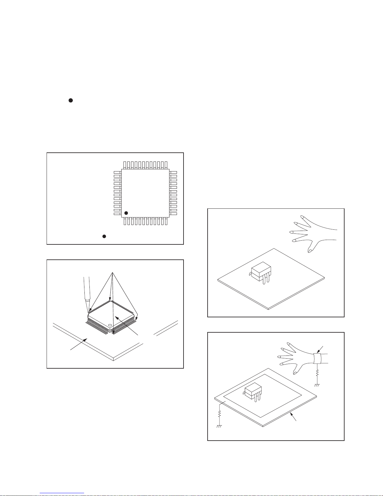
2. Installation
1. Using desoldering braid, remove the solder from
the foil of each pin of the flat pack-IC on the CBA
so you can install a replacement flat pack-IC more
easily.
2. The “
” mark on the flat pack-IC indicates pin 1.
(See Fig. S-1-7.) Be sure this mark matches the 1
on the PCB when positioning for installation. Then
presolder the four corners of the flat pack-IC. (See
Fig. S-1-8.)
3. Solder all pins of the flat pack-IC. Be sure that
none of the pins have solder bridges.
Instructions for Handling Semi-
Special Information BGA IC & Flat Pack-IC
conductors
Electrostatic breakdown of the semi-conductors may
occur due to a potential difference caused by
electrostatic charge
during unpacking or repair work.
1. Ground for Human Body
Be sure to wear a grounding band (1 MΩ) that is
properly grounded to remove any static electricity that
may be charged on the body.
2. Ground for Workbench
Be sure to place a conductive sheet or copper plate
with proper grounding (1 MΩ) on the workbench or
other surface, where the semi-conductors are to be
placed. Because the static electricity charge on
clothing will not escape through the body grounding
band, b
e
careful to avoid contacting semi-conductors
with your clothing.
Example :
Pin 1 of the Flat Pack-IC
is indicated by a " " mark.
Fig. S-1-7
Presolder
CBA
Flat Pack-IC
Fig. S-1-8
<Incorrect>
CBA
Grounding Band
Conductive Sheet or
Copper Plate
1MΩ
1MΩ
<Correct>
CBA

Direction of Use
9-1
Remote control
a ( Standby-On )
Switches the home theater on or to
•
standby.
When EasyLink is enabled, press
•
and hold for at least three seconds
to switch all connected HDMI CEC
compliant devices to standby.
b OPEN/CLOSE
Opens or closes the disc compartment.
22
17
1
3
2
4
5
6
11
13
12
15
14
16
18
19
7
8
10
920
21
23
Your home theater
Congratulations on your purchase, and welcome
to Philips! To fully benefit
from the support that
Philips offers, register your home theater at
www.philips.com/welcome.
Main unit
a Disc compartment
b ( Open/Close )
Opens or closes the disc compartment.
c ( Play/Pause )
Starts, pauses or resumes disc play.
d SOURCE
Selects an audio/video source for the home
theater.
e ( Standby-On )
Switches the home theater on or to
standby.
f +/- ( Volume )
Increases or decreases volume.
g Display panel
*The following excerpt of the DFU/QSG serves as an introduction to the set.
The Complete Direction for Use can be download in different languages from
the internet site of Philips Customer care Center : www.p4c.philips.com

Direction of Use
Remote Control
9-2
p HDMI / ANGLE
Selects video resolution of HDMI
•
output from the home theater.
Displays options for different camera
•
angles.
q SUBTITLE
Selects subtitle language for video.
r SURROUND
Selects Dolby Virtual Speaker surround
sound.
s +/-
Increases or decreases volume.
t ( Mute )
Mutes or restores volume.
u / (Previous/Next )
Skips to the previous or next track, chapter
or � le.
v BACK
Returns to a previous menu screen.
w OK
Con� rms an entry or selection.
c Audio Source
• DISC: Switches to disc source.
• USB: Switches to USB storage device.
• RADIO: Switches to FM radio.
• AUDIO SOURCE : Selects an audio
input source.
• DOCK for iPod: Switches to Philips
Dock for iPod/iPhone.
d SETUP
Accesses or exits the setup menu.
e ( Navigation buttons )
Navigate menus.
•
In video mode, press left or right to •
fast backward or fast forward.
In radio mode, press left or right to
•
search a radio station; press up or
down to � ne tune a radio frequency.
f ( Fast Backward ) ( Fast Forward )
Fast backwards or fast forwards. Press
repeatedly to change the search speed.
g INFO
Displays information about what is playing.
h ( Play/Pause )
Starts, pauses or resumes disc play.
i ( Stop )
Stops disc play.
•
In radio mode, erases the current •
preset radio station.
j TREBLE / BASS
Changes treble or bass. Use with +/-.
k Numeric buttons
Selects an item to play.
l AUDIO SYNC
Selects an audio language or channel.
•
Press and hold to synchronize audio •
with video. Use with +/-.
m SOUND MODE
Selects a predefined sound effect.
n REPEAT /PROGRAM
Selects a repeat or shuffle mode.
•
In radio mode, programs radio stations.•
o
ZOOM
Zooms into a video scene or picture.
Direction of Use
9-3
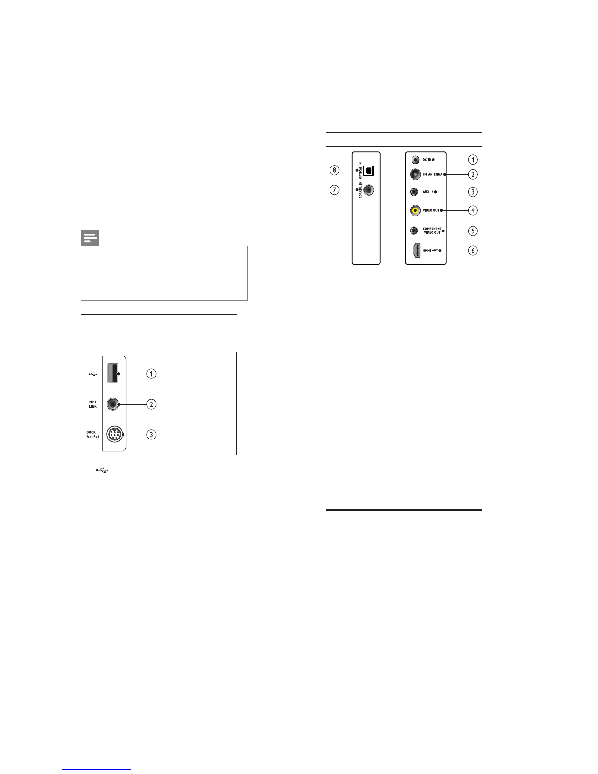
Back connectors
a DC IN
Connects to the AC-DC adapter.
b FM ANTENNA
Connects the FM antenna for radio
reception.
c AUX IN
Connects to the analog audio output on the
TV or an analog device.
d VIDEO OUT
Connects to the composite video input on
the TV.
e COMPONENT VIDEO OUT
Connects to the component video input on
the TV.
f HDMI OUT
Connects to the HDMI input on the TV.
g COAXIAL IN
Connects to the coaxial audio output on
the TV or a digital device.
h OPTICAL IN
Connects to the optical audio output on
the TV or a digita
l devic
e.
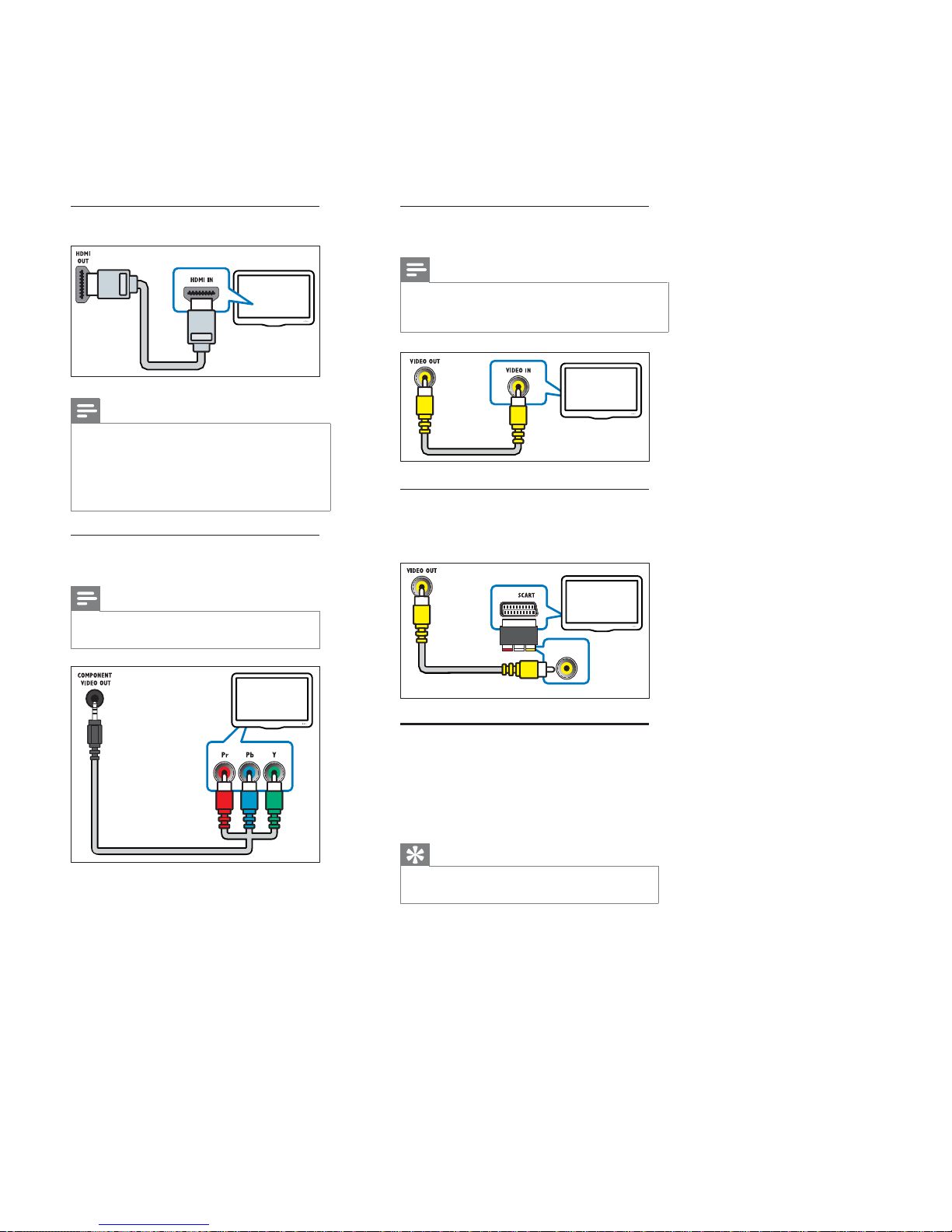
Connect to the TV
Connect your home theater directly to a TV
through one of the following connectors (from
highest to basic quality video):
a HDMI
b Component video
c Composite video
d SCART
Connect your home
theater
This section helps you connect your home theater
to a TV and other devices. The basic connections
of the home theater with its accessories are
provided in the Quick Start. For a comprehensive
interactive guide, see www.connectivityguide.
philips.com.
Note
Refer to the type plate at the back or bottom •
of the product for identification and supply
ratings.
Before you make or change any connections,
•
ensure that all devices are disconnected from
the power outlet.
Connectors
Side connectors
a ( USB )
Audio, video or picture input from a USB
storage device.
b MP3 LINK
Audio input from an MP3 player.
c DOCK for iPod
Connects to a Philips Dock for iPod/iPhone.
(sold separately)
Direction of Use
9-4
Option 3: Connect to the TV through
composite video (CVBS)
Note
The composite video cable or connector might •
be labeled AV IN,VIDEO IN,COMPOSITE or
BASEBAND.
Option 4: Connect to the TV through
SCART
Use the supplied scart adapter.
Connect audio from TV or
other devices
Use your home theater to play audio from the TV
or other devices such as a cable box. Choose from
the following connectors.
Tip
Press • AUDIO SOURC Erepeatedly to select
the audio output of your connection.
TV
TV
Option 1: Connect to the TV through
HDMI
Note
If the HDTV has a DVI connector, connect •
using an HDMI/DVI adapter.
If the TV supports EasyLink HDMI CEC,
•
control the home theater and TV with one
remote control (see ‘Use Philips EasyLink’ on
page 13 ).
Option 2: Connect to the TV through
YPbPr (component video)
Note
The component video cable or connector •
might be labeled Y Cb Cr or YUV
TV
TV
Component Video In
 Loading...