

Philips HTS5110, HTS5110/12, HTS5110/51, HTS5110/98 Service Manual
Published by KC-LQ 1004 AVM Printed in he Netherlands
HTS5110/12/51/98
Subject to modification EN 3139 785 35230
Home Theater System
Contents
Page
Contents
Page
©
Copyright 2010 Philips Consumer Electronics B.V. Eindhoven, The Netherlands.
All rights reserved. No part of this publication may be reproduced, stored in a
retrieval system or transmitted, in any form or by any means, electronic,
mechanical, photocopying, or otherwise without the prior permission of Philips.
Version 1.0
2 Importand Safety Precautions ......................... 2-1 to 2-2
3 Safety Check After Servicing ..................................... 3-1
4 Safety Information Genard Notes & Lead Free
5 Standard Notes For Servicing ................................... 5-1
6 Special Information of BGA IC & Flat
7 Direction of USE ............................................. 7-1 to 7-5
1 Technical Specification and Connection Facilities
8 Cabinet Disassembly Instructions ................... 8-1 to 8-3
9 Troubleshooting ......................................................... 9-1
10 Software Upgrading Procedure ............................. 10-1
11 Software Version Check Procedure ...................... 10-2
12 Block Diagram ....................................................... 11-1
13 Wiring Diagram ..................................................... 12-1
14 Main Unit--Touch Board Diagram
Circuit Diagram ............................................13-1
Layout Diagram ...........................................13-1
15 Main Unit--VFD Display Board Diagram
Circuit Diagram ............................................14-1
PT6311 IC Specification ..............................14-2
Layout Diagram ...........................................14-3
16 Main Unit--Decoder Board Diagram
Circuit Diagram ...............................15-1 to 15-3
Circuit Diagram ...............................15-6 to 15-9
EN29LV320A IC Specification ....................15-5
UDA1355H IC Specification .....................15-10
Layout Diagram ........................................15-11
M12L64164A IC Specification ....................15-4
17 Main Unit--Radio Transmit Board Diagram
Circuit Diagram ................................16-1 to 16-3
Layout Diagram ...........................................16-4
20 Main Unit Exploded View ...................................... 19-1
18 Subwoofer--Radio Receiver Board Diagram
Circuit Diagram ................................17-1 to 17-3
Layout Diagram ...........................................17-4
19 Subwoofer--Power Board Diagram
Circuit Diagram ................................18-1 to 18-2
Layout Diagram ...........................................18-3
21 Subwoofer Exploded View .................................... 19-2
22 Revision List .......................................................... 20-1
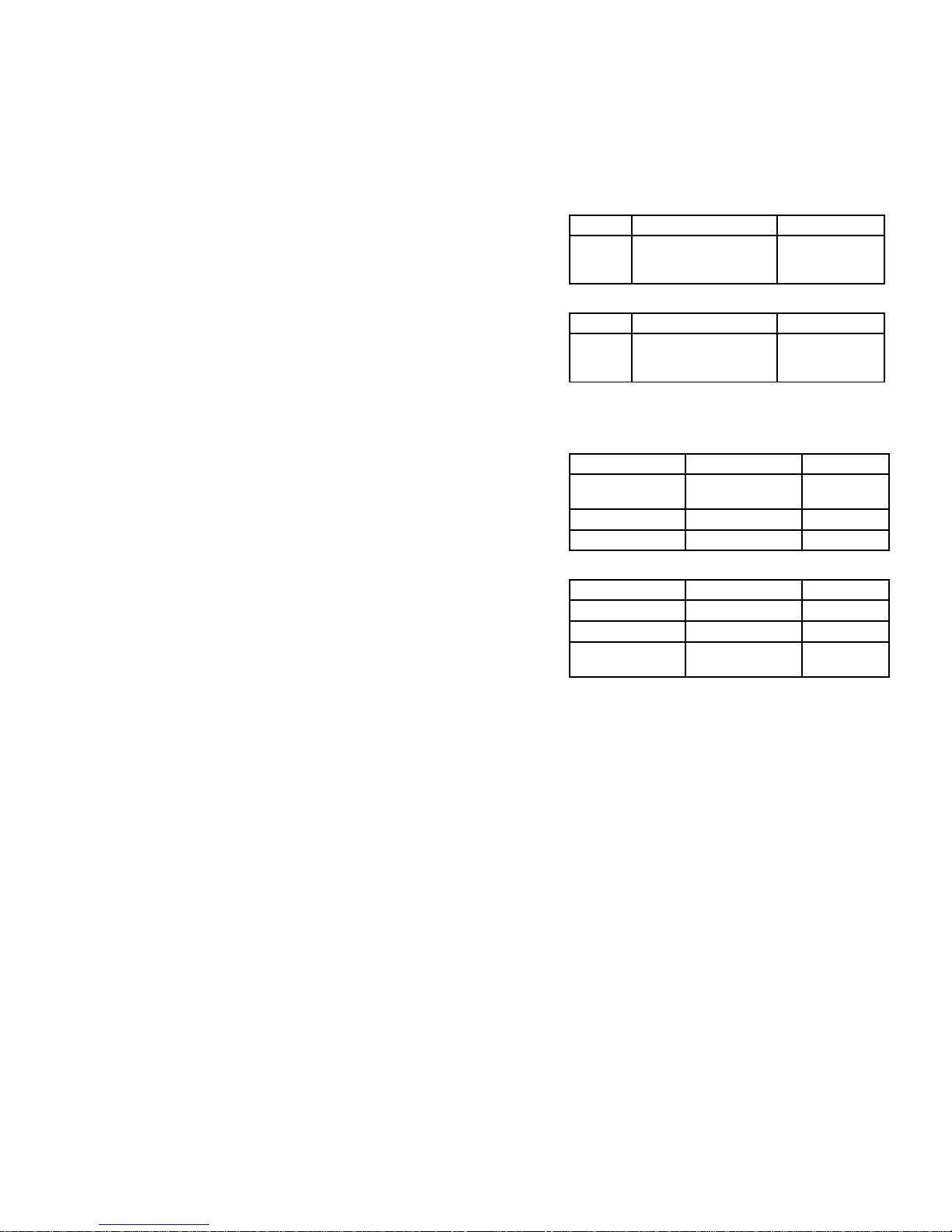
Features
RDS
Voltage Selector
ECO Standby
DTS
Feature
Different
/12
/51 /98
Pack-IC.................................... 6-1 to 6-3
Requirement ....................................... 4-1
................................................ 1-1 to 1-2

Technical Specifications and Connection Facilities
1. Technical Specifications and Connection Facilities
1.1 PCB Locations
Main Unit
Subwoofer
1.2 General:
Power supply : 100-240V, ~50 Hz
Power consumption : 35 W
Standby power consumption : < 1 W
1.4 Analog Inputs/Outputs
1.4.1 MP3 LINK IN of Cinch connector to be used for
measurements(direct input from Front end)
MP3 LINK Performance:
Frequency Response : -1 ± 3dB (150 to 20KHz)
Input and output voltages : 500 mV / 20 kOhm
1.3 Radio
Tuning Frequency Range : 87.5 MHz – 108 MHz
Antenna Level for 40dB luminance
S/N (video unweighted) at 75Ω : ≤ 71dBμV (High End)
≤ 50dBμV (Low End)
Automatic Search Tuning:
Scanning time auto search without
RF Signal : < 2.5 min.
(Typical 3 minutes)
Stop level (vision carrier) : ≥ 31dBμV
Maximum tuning error during
operation (drift) : ≤ 50kHz
Maximum tuning error of a recalled
program : ± 22.5 kHz
Tuning Principles:
Automatic system recognition
Decoder Board
VFD Display Board
USB Board
Touch Board-2
Touch Board-1
Radio Transmit
Board
1-1
Power Board
Power Control
Switch 110/220V
(for 55/98version)
Radio Receiver
Board
1.4.2 Video Rear output Connector
CVBS output:
DC Level : 0V+1V
Amplitude output: : 1.04V
Technical Specifications and Connection Facilities
1-2
1.6 Dimension and Weight
1.5 (AUDIO OUT) Coaxial Digital
LPCM : according IEC 60958
MPEG 1, MPEG 2, AC3 : according IEC 61937
DTS : according IEC 61937 +
addendum
1.5.1 USB
Compatibility : USB 2.0
Type of connector : Series A Connector
1.5.2 HDMI Output
Set Dimension W x H x D : 790.6 x 100.3 x 50mm
Net Weight : 1.5kg
Subwoofer Dimension W x H x D : 182 x 365 x 306mm
Net Weight : 6kg
Compatibility : HDMI version 1.3
Type of connector : Type A connector
(19 pins)
1.7 Video Performance
1.7.1 SNR
PAL
RGB CVBS Y/C
≥ 55 dB Lumincance: ≥ 55 dB
Chroma: ≥ 55 dB (AM)
≥ 52 dB (PM)
Y: ≥ 57 dB
C: ≥ 57 dB (AM)
≥ 54 dB (PM)
NTSC
Y Pb Pr CVBS Y/C
≥ 55 dB Lumincance: ≥ 55 dB
Chroma: ≥ 54 dB (AM)
≥ 54 dB (PM)
Y: ≥ 55 dB
C: ≥ 54 dB (AM)
≥ 54 dB (PM)
1.7.2 Bandwidth
PAL
RGB CVBS Y/C
0.5 to 4 MHz:+1dB/
-2dB
0.5 to 4 MHz:+1dB/
-2dB
Y:4.8MHz-3dB
4.8 MHz:-3dB 4.8 MHz:-3dB C:700 kHz
5.8 MHz:-6dB 5.8 MHz:-6dB
NTSC
YPbPr CVBS Y/C
4.2 MHz:-3dB 4.2 MHz:-3dB Y:4.2MHz-3dB
5.8 MHz:-6dB 5.8 MHz:-6dB C:≥ 700 kHz
With Pscan:
8.4MHz -3dB

Electronics N.V. bears no responsibility
for improper wall mounting that results in
accident, injury or damage.
For speakers with stands, use only the
supplied stands. Secure the stands to
the speakers tightly. Place the assembled
stands on flat, level surfaces that can
support the combined weight of the
speaker and stand.
Never place the product or any objects
on power cords or on other electrical
equipment.
If the product is transported in
temperatures below 5°C, unpack the
product and wait until its temperature
matches room temperature before
connecting it to the power outlet.
Visible and invisible laser radiation when
open. Avoid exposure to beam.
Do not touch the disc optical lens inside
the disc compartment.
Risk of overheating!
Never install this product in a confined
space. Always leave a space of at least
four inches around the product for
ventilation. Ensure curtains or other
objects never cover the ventilation slots
on the product.
Risk of contamination!
Do not mix batteries (old and new or
carbon and alkaline, etc.).
Remove batteries if they are exhausted
or if the remote control is not to be used
for a long time.
Batteries contain chemical substances,
they should be disposed of properly.
Product care
Do not insert any objects other than discs
into the disc compartment.
Do not insert warped or cracked discs
into the disc compartment.
Remove discs from the disc compartment
if you are not using the product for an
extended period of time.
•
•
•
•
•
•
•
•
•
•
•
•
Only use microfiber cloth to clean the
product.
•
Important
Important Safety Precautions
Read and understand all instructions before you use
your home theater. If damage is caused by failure to
follow instructions, the warranty does not apply.
Safety
Risk of electric shock or fire!
Never expose the product and
accessories to rain or water. Never place
liquid containers, such as vases, near the
product. If liquids are spilt on or into the
product, disconnect it from the power
outlet immediately. Contact Philips
Consumer Care to have the product
checked before use.
Never place the product and accessories
near naked flames or other heat sources,
including direct sunlight.
Never insert objects into the ventilation
slots or other openings on the product.
Where the mains plug or an appliance
coupler is used as the disconnect device,
the disconnect device shall remain readily
operable.
Disconnect the product from the power
outlet before lightning storms.
When you disconnect the power cord,
always pull the plug, never the cable.
Risk of short circuit or fire!
Before you connect the product to the
power outlet, ensure that the power
voltage matches the value printed on the
back or bottom of the product. Never
connect the product to the power outlet
if the voltage is different.
Risk of injury or damage to the home theater!
For wall-mountable products, use only
the supplied wall mount bracket. Secure
the wall mount to a wall that can support
the combined weight of the product
and the wall mount. Koninklijke Philips
•
•
•
•
•
•
•
•
2-1

Disposal of your old product and
batteries
Your product is designed and manufactured
with high quality materials and components,
which can be recycled and reused.
When this crossed-out wheeled bin symbol
is attached to a product it means that the
product is covered by the European Directive
2002/96/EC. Please inform yourself about the
local separate collection system for electrical
and electronic products.
Please act according to your local rules and
do not dispose of your old products with your
normal household waste.
Correct disposal of your old product helps to
prevent potential negative consequences for
the environment and human health.
Your product contains batteries covered by
the European Directive 2006/66/EC, which
cannot be disposed with normal household
waste.
Please inform yourself about the local rules
on separate collection of batteries because
correct disposal helps to prevent negative
consequences for the environmental and
human health.
Important Safety Precautions
2-2
3-1
Safety Check after Servicing
Examine the area surrounding the repaired location for damage or deterioration. Observe that screws, parts, and
wires have been returned to their original positions. Afterwards, do the following tests and confirm the specified
values to verify compliance with safety standards.
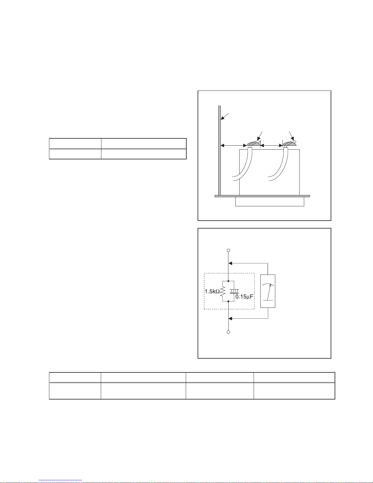
1. Clearance Distance
When replacing primary circuit components, confirm
specified clearance distance (d) and (d’) between
soldered terminals, and between terminals and
surrounding metallic parts. (See Fig. 1)
Table 1: Ratings for selected area
Note: This table is unofficial and for reference only. Be
sure to confirm the precise values.
2. Leakage Current Test
Confirm the specified (or lower) leakage current
between B (earth ground, power cord plug prongs) and
externally exposed accessible parts (RF terminals,
antenna terminals, video and audio input and output
terminals, microphone jacks, earphone jacks, etc.) is
lower than or equal to the specified value in the table
below.
Measuring Method (Power ON):
Insert load Z between B (earth ground, power cord plug
prongs) and exposed accessible parts. Use an AC
voltmeter to measure across the terminals of load Z.
See Fig. 2 and the following table.
Table 2: Leakage current ratings for selected areas
Note: This table is unofficial and for reference only. Be sure to confirm the precise values.
AC Line Voltage Clearance Distance (d), (d’)
110V~220V ≥ 3.2 mm (0.126 inches)
AC Line Voltage Load Z Leakage Current (i) Earth Ground (B) to:
110V~220V
0.15 µF CAP. & 1.5 kΩ RES.
Connected in parallel
i ≤ 0.5 mA Peak Exposed accessible parts
Chassis or Secondary Conductor
Primary Circuit
Fig. 1
d' d
AC Voltmeter
(High Impedance)
Exposed Accessible Part
B
Earth Ground
Power Cord Plug Prongs
Z
Fig. 2

1 Safety Instructions
1.1 General Safety
Safety regulations require that during a repair:
• Connect the unit to the mains via an isolation transformer.
• Replace safety components, indicated by the symbol
,
only by components identical to the original ones. Any
other component substitution (other than original type)
may increase risk of fire or electrical shock hazard.
Safety regulations require that after a repair, you must return
the unit in its original condition. Pay, in particular, attention to
the following points:
• Route the wires/cables correctly, and fix them with the
mounted cable clamps.
• Check the insulation of the mains lead for external
damage.
• Check the electrical DC resistance between the mains
plug and the secondary side:
1. Unplug the mains cord, and connect a wire between
the two pins of the mains plug.
2. Set the mains switch to the ‘on’ position (keep the
mains cord unplugged!).
3. Measure the resistance value between the mains
plug and the front panel, controls, and chassis
bottom.
4. Repair or correct unit when the resistance
measurement is less than 1 MΩ.
5. Verify this, before you return the unit to the customer/
user (ref. UL-standard no. 1492).
6. Switch the unit ‘off’, and remove the wire between the
two pins of the mains plug.
2 Warnings
2.1 General
• All ICs and many other semiconductors are susceptible to
electrostatic discharges (ESD,
). Careless handling
during repair can reduce life drastically. Make sure that,
during repair, you are at the same potential as the mass
of the set by a wristband with resistance. Keep
components and tools at this same potential.
Available ESD protection equipment:
– Complete kit ESD3 (small tablemat, wristband,
connection box, extension cable and earth cable)
4822 310 10671.
– Wristband tester 4822 344 13999.
• Be careful during measurements in the live voltage
section. The primary side of the power supply, including
the heatsink, carries live mains voltage when you
connect the player to the mains (even when the
player is ‘off’!). It is possible to touch copper tracks and/
or components in this unshielded primary area, when
you service the player. Service personnel must take
precautions to prevent touching this area or components
in this area. A ‘lightning stroke’ and a stripe-marked
printing on the printed wiring board, indicate the primary
side of the power supply.
• Never replace modules, or components, while the unit is
‘on’.
Safety Information, General Notes & Lead Free Requirements
4-1
5-1
Standard Notes for Servicing
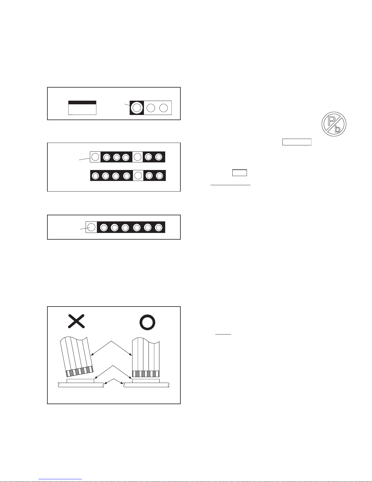
Circuit Board Indications
1. The output pin of the 3 pin Regulator ICs is
indicated as shown.
2. For other ICs, pin 1 and every fifth pin are
indicated as shown.
3. The 1st pin of every male connector is indicated as
shown.
Instructions for Connectors
1. When you connect or disconnect the FFC (Flexible
Foil Connector) cable, be sure to first disconnect
the AC cord.
2. FFC (Flexible Foil Connector) cable should be
inserted parallel into the connector, not at an
angle.
Pb (Lead) Free Solder
When soldering, be sure to use the Pb free solder.
Information about lead-free soldering
Philips CE is producing lead-free sets from 1.1.2005
onwards.
IDENTIFICATION
Regardless of special logo (not always
indicated)
One must treat all sets from
onwards, according to the next rule:
Serial Number gives a 14-digit. Digit 5&6 shows the
YEAR, and digit 7&8 shows the WEEK.
So from onwards=from 1 Jan 2005 onwards
Important note : In fact also products of year 2004
must be treated in this way as long as you avoid
mixing solder-alloys (leaded/ lead-free). So best to
always use SAC305 and the higher temperatures
belong to this.
Due to lead-free technology some rules have to be
respected by the workshop during a repair:
• Use only lead-free solder alloy Philips SAC305 with
order code 0622 149 00106. If lead-free solderpaste is required, please contact the manufacturer
of your solder-equipment. In general use of solderpaste within workshops should be avoided because
paste is not easy to store and to handle.
• Use only adequate solder tools applicable for leadfree solder alloy. The solder tool must be able
• To reach at least a solder-temperature of 400°C,
• To stabilize the adjusted temperature at the solder-
tip
• To exchange solder-tips for different applications.
• Adjust your solder tool so that a temperature around
360°C
- 380°C is reached and stabilized at the
solder joint. Heating-time of the solder-joint should
not exceed ~ 4 sec. Avoid temperatures above
400°C otherwise wear-out of tips will rise drastically
and flux-fluid will be destroyed. To avoid wear-out of
tips switch off un-used equipment, or reduce heat.
• Mix of lead-free solder alloy / parts with leaded
solder alloy / parts is possible but PHILIPS
recommends strongly to avoid mixed solder alloy
types (leaded and lead-free).
If one cannot avoid or does not know whether
product is lead-free, clean carefully the solder-joint
from old solder alloy and re-solder with new solder
alloy (SAC305).
• Use only original spare-parts listed in the ServiceManuals. Not listed standard-material (commodities)
has to be purchased at external companies.
Top View
Out
In
Bottom View
Input
5
10
Pin 1
Pin 1
FFC Cable
Connector
CBA
* Be careful to avoid a short circuit.
1 Jan 2005
0501
6-1
•
Special information for BGA-ICs:
- always use the 12nc-recognizable soldering
temperature profile of the specific BGA (for desoldering always use the lead-free temperature
profile, in case of doubt)
- lead free BGA-ICs will be delivered in so-called
'dry-packaging' (sealed pack including a silica gel
pack) to protect the IC against moisture. After
opening, dependent of MSL-level seen on indicatorlabel in the bag, the BGA-IC possibly still has to be
baked dry. (MSL=Moisture Sensitivity Level). This
will be communicated via AYS-website.
Do not re-use BGAs at all.
• For sets produced before 1.1.2005 (except products
of 2004), containing leaded solder-alloy and
components, all needed spare-parts will be available
till the end of the service-period. For repair of such
sets nothing changes.
• On our website
www.atyourservice.ce.Philips.com
you find more
information to:
• BGA-de-/soldering (+ baking instructions)
• Heating-profiles of BGAs and other ICs used in
Philips-sets
You will find this and more technical information within
the “magazine”, chapter “workshop news”.
For additional questions please contact your local
repair-helpdesk.
How to Remove / Install Flat Pack-IC
Special Information of BGA IC & Flat Pack-IC
1. Removal
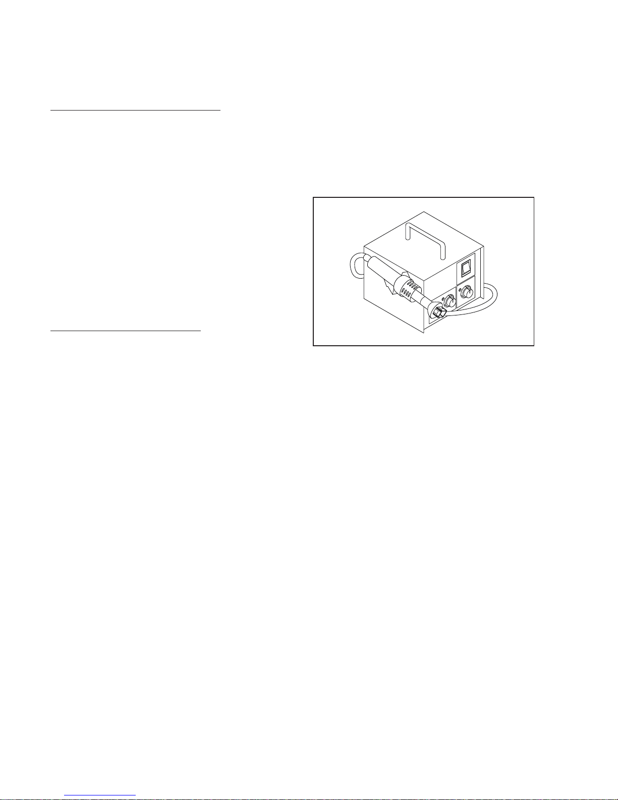
With Hot-Air Flat Pack-IC Desoldering Machine:
1. Prepare the hot-air flat pack-IC desoldering
machine, then apply hot air to the Flat Pack-IC
(about 5 to 6 seconds). (Fig. S-1-1)
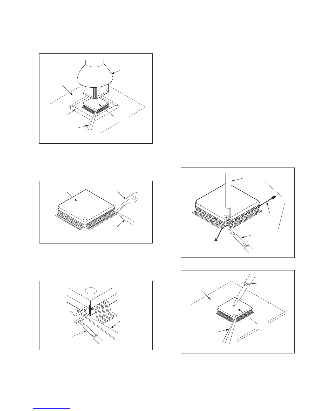
2. Remove the flat pack-IC with tweezers while
applying the hot air.
3. Bottom of the flat pack-IC is fixed with glue to the
CBA; when removing entire flat pack-IC, first apply
soldering iron to center of the flat pack-IC and heat
up. Then remove (glue will be melted). (Fig. S-1-6)
4. Release the flat pack-IC from the CBA using
tweezers. (Fig. S-1-6)
CAUTION:
1. The Flat Pack-IC shape may differ by models. Use
an appropriate hot-air flat pack-IC desoldering
machine, whose shape matches that of the Flat
Pack-IC.
2. Do not supply hot air to the chip parts around the
flat pack-IC for over 6 seconds because damage
to the chip parts may occur. Put masking tape
around the flat pack-IC to protect other parts from
damage. (Fig. S-1-2)
Fig. S-1-1
3. The flat pack-IC on the CBA is affixed with glue, so
be careful not to break or damage the foil of each
pin or the solder lands under the IC when
removing it.
With Soldering Iron:
1. Using desoldering braid, remove the solder from
all pins of the flat pack-IC. When you use solder
flux which is applied to all pins of the flat pack-IC,
you can remove it easily. (Fig. S-1-3)
2. Lift each lead of the flat pack-IC upward one by
one, using a sharp pin or wire to which solder will
not adhere (iron wire). When heating the pins, use
a fine tip soldering iron or a hot air desoldering
machine. (Fig. S-1-4)
3. Bottom of the flat pack-IC is fixed with glue to the
CBA; when removing entire flat pack-IC, first apply
soldering iron to center of the flat pack-IC and heat
up. Then remove (glue will be melted). (Fig. S-1-6)
4. Release the flat pack-IC from the CBA using
tweezers. (Fig. S-1-6)
With Iron Wire:
1. Using desoldering braid, remove the solder from
all pins of the flat pack-IC. When you use solder
flux which is applied to all pins of the flat pack-IC,
you can remove it easily. (Fig. S-1-3)
2. Affix the wire to a workbench or solid mounting
point, as shown in Fig. S-1-5.
3. While heating the pins using a fine tip soldering
iron or hot air blower, pull up the wire as the solder
melts so as to lift the IC leads from the CBA
contact pads as shown in Fig. S-1-5.
4. Bottom of the flat pack-IC is fixed with glue to the
CBA; when removing entire flat pack-IC, first apply
soldering iron to center of the flat pack-IC and heat
up. Then remove (glue will be melted). (Fig. S-1-6)
5. Release the flat pack-IC from the CBA using
tweezers. (Fig. S-1-6)
Note: When using a soldering iron, care must be
taken to ensure that the flat pack-IC is not
being held by glue. When the flat pack-IC is
removed from the CBA, handle it gently
because it may be damaged if force is applied.
Hot-air
Flat Pack-IC
Desoldering
Machine
CBA
Flat Pack-IC
Tweezers
Masking
Tape
Fig. S-1-2
Flat Pack-IC
Desoldering Braid
Soldering Iron
Fig. S-1-3
Fine Tip
Soldering Iron
Sharp
Pin
Fig. S-1-4
To Solid
Mounting Point
Soldering Iron
Iron Wire
or
Hot Air Blower
Fig. S-1-5
Fine Tip
Soldering Iron
CBA
Flat Pack-IC
Tweezers
Fig. S-1-6
6-2
6-3
2. Installation
1. Using desoldering braid, remove the solder from
the foil of each pin of the flat pack-IC on the CBA
so you can install a replacement flat pack-IC more
easily.
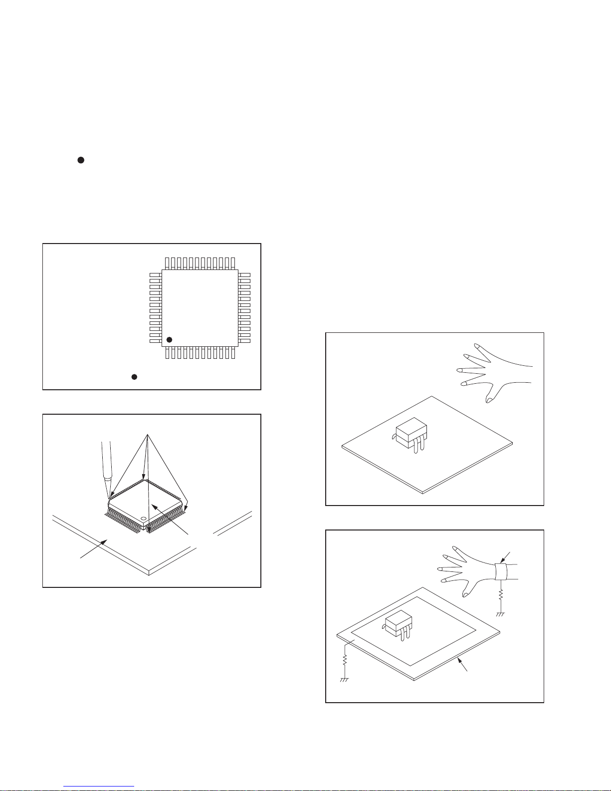
2. The “
” mark on the flat pack-IC indicates pin 1.
(See Fig. S-1-7.) Be sure this mark matches the 1
on the PCB when positioning for installation. Then
presolder the four corners of the flat pack-IC. (See
Fig. S-1-8.)
3. Solder all pins of the flat pack-IC. Be sure that
none of the pins have solder bridges.
Instructions for Handling Semi-
Special Information BGA IC & Flat Pack-IC
conductors
Electrostatic breakdown of the semi-conductors may
occur due to a potential difference caused by
electrostatic charge during unpacking or repair work.
1. Ground for Human Body
Be sure to wear a grounding band (1 MΩ) that is
properly grounded to remove any static electricity that
may be charged on the body.
2. Ground for Workbench
Be sure to place a conductive sheet or copper plate
with proper grounding (1 MΩ) on the workbench or
other surface, where the semi-conductors are to be
placed. Because the static electricity charge on
clothing will not escape through the body grounding
band, be careful to avoid contacting semi-conductors
with your clothing.
Example :
Pin 1 of the Flat Pack-IC
is indicated by a " " mark.
Fig. S-1-7
Presolder
CBA
Flat Pack-IC
Fig. S-1-8
<Incorrect>
CBA
Grounding Band
Conductive Sheet or
Copper Plate
1MΩ
1MΩ
<Correct>
CBA
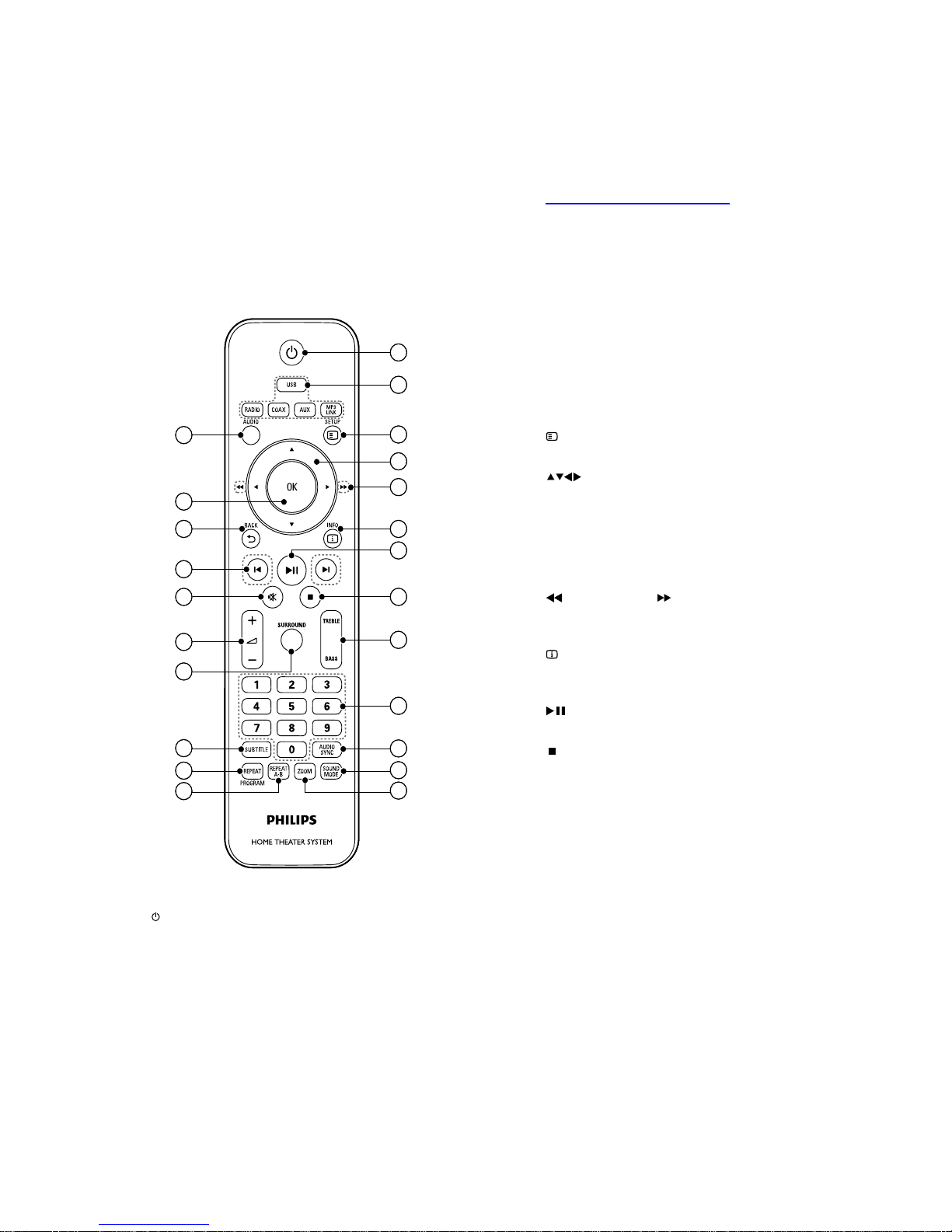
RADIO: Switches to FM radio.
COAX: Switches to coaxial digital
input source.
AUX: Switches to auxiliary input
source.
MP3 LINK: Switches to MP3 Link
input source.
c
SETUP
Accesses or exits the setup menu.
d
(Navigation buttons)
Navigate menus.
In video mode, press left or right to
fast backward or fast forward.
In radio mode, press left or right to
search a radio station; press up or
down to fine tune a radio frequency.
e
(Fast Backward) (Fast Forward)
Fast backwards or fast forwards. Press
repeatedly to change the search speed.
f
INFO
Displays information about what is
playing.
g
(Play/Pause)
Starts, pauses or resumes playback.
h
(Stop)
Stops playback.
In radio mode, erases the current
preset radio station.
i TREBLE / BASS
Changes treble or bass. Use with +/-.
j Numeric buttons
Selects an item to play.
k AUDIO SYNC
Press and hold to access the setting for
audio sync, then press +/- to set the
audio delay time.
l SOUND MODE
Selects a predefined sound effect.
m ZOOM
Zooms into a video scene or picture.
n REPEAT A-B
•
•
•
•
•
•
•
•
•
a
(Standby-On)
Switches the home theater on or to
standby.
When EasyLink is enabled, press
and hold for at least three seconds
to switch all connected HDMI CEC
compliant devices to standby.
b Audio Source
USB: Switches to USB storage
device.
•
•
•
19
18
17
16
15
1
2
3
5
4
7
6
9
8
12
11
10
14
13
22
21
20
23
19
18
17
16
15
1
2
3
5
4
7
6
9
8
12
11
10
14
13
22
21
20
23
Direction of Use
*The following excerpt of the DFU/QSG serves as an introduction to the set.
The Complete Direction for Use can be download in different languages from
the internet site of Philips Customer care Center: www.p4c.philips.com
Remote Control
7-1

Marks two points within a chapter or
track for repeat play, or turns off repeat
mode.
o REPEAT / PROGRAM
Selects a repeat or shuffle mode.
In radio mode, programs radio
stations.
p SUBTITLE
Selects a subtitle language for video.
q SURROUND
Selects Dolby Virtual Speaker surround
sound.
r
+/-
Increases or decreases volume.
s
(Mute)
Mutes or restores volume.
t
/ (Previous/Next)
Skips to the previous or next track,
chapter or file.
u
BACK
Returns to a previous menu screen.
v OK
Confirms an entry or selection.
w AUDIO
Selects an audio language or channel.
•
•
Direction of Use
Remote Control
7-2
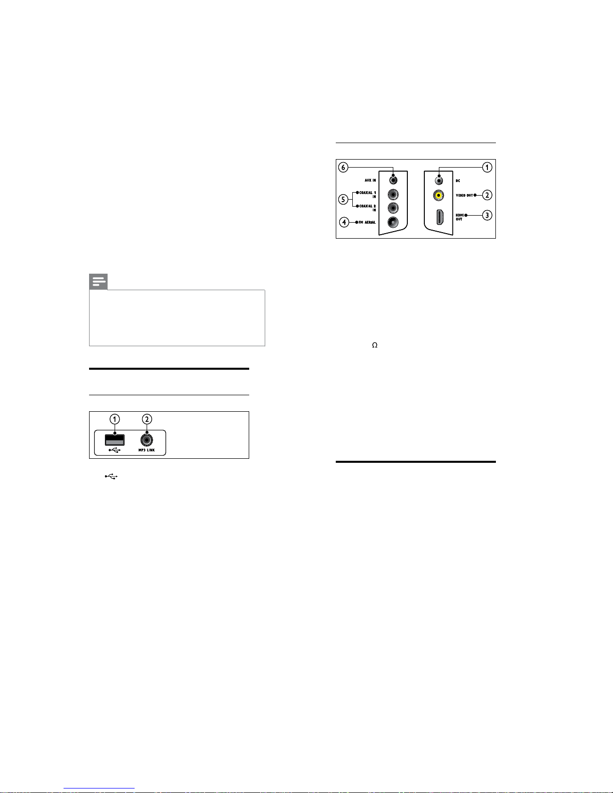
Back connectors
a DC IN
Connects to the AC-DC adapter.
b VIDEO OUT (CVBS)
Connects to the composite video input
on the TV.
c HDMI OUT
Connects to the HDMI input on the TV.
d FM75
Connects the FM antenna for radio
reception.
e DIGITAL IN-COAXIAL
Connects to the coaxial audio output on
the TV or a digital device.
f AUX IN
Connects to the analog audio output on the
TV or an analog device.
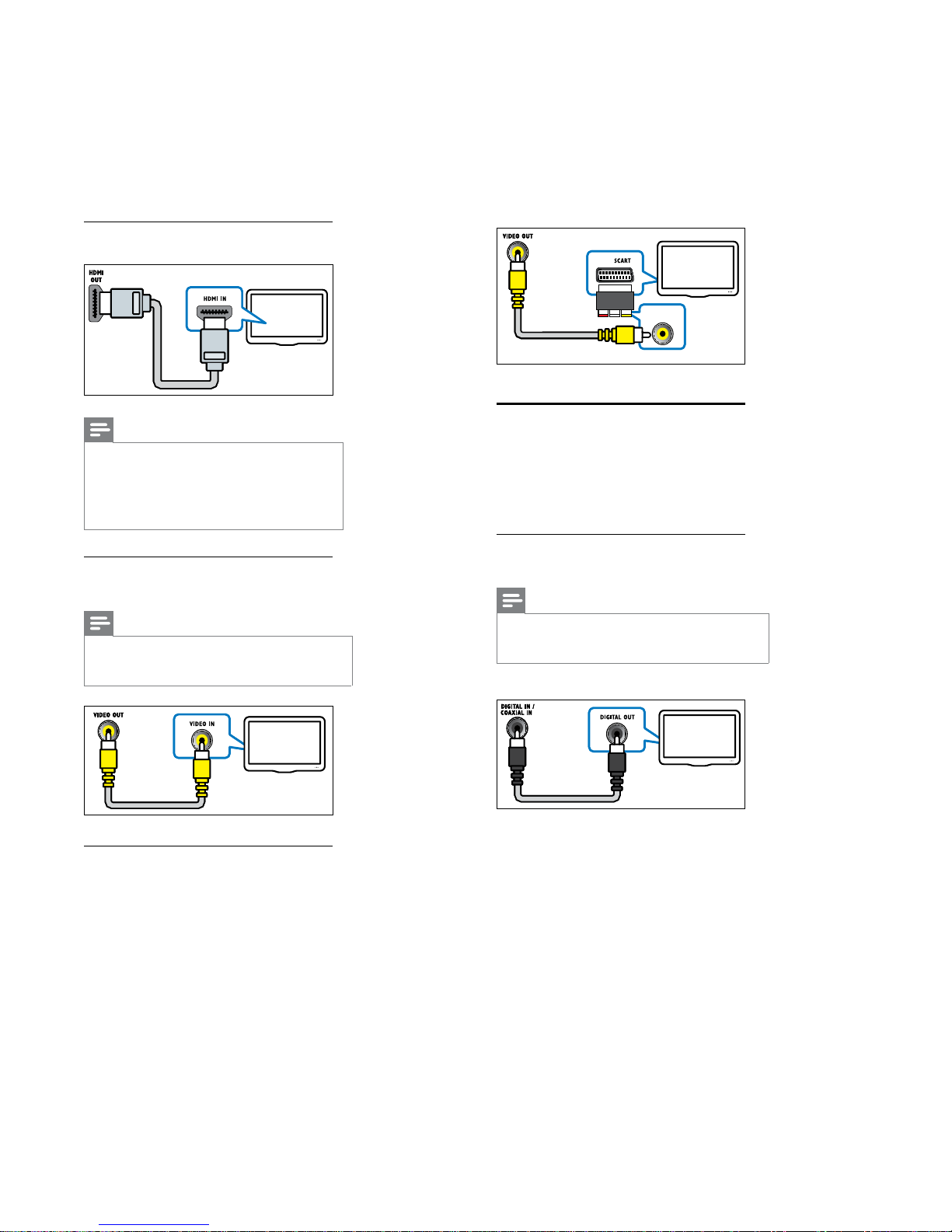
Connect to the TV
Connect your home theater directly to a TV
through one of the following connectors (from
highest to basic quality video):
a HDMI
b Composite video
c SCART
Connect your
Direction of Use
home theater
This section helps you connect your home
theater to a TV and other devices. The basic
connections of the home theater with its
accessories are provided in the Quick Start. For
a comprehensive interactive guide, see www.
connectivityguide.philips.com.
Note
Refer to the type plate at the back or bottom
of the product for identification and supply
ratings.
Before you make or change any connections,
ensure that all devices are disconnected from
the power outlet.
•
•
Connectors
Front connectors
a (USB)
Audio, video or picture input from a USB
storage device.
b MP3 LINK
Audio input from an MP3 player.
7-3
Connect audio from TV or
other devices
Use your home theater to play audio from
the TV or other devices such as a cable box.
Choose from the following connectors.
Option 1: Connect audio through a
digital coaxial cable
Note
The digital coaxial cable or connector might be
labeled COAXIAL DIGITAL OUT or SPDIF
OUT.
•
(Cable not supplied)
Option 1: Connect to the TV through
HDMI
Note
If the HDTV has a DVI connector, connect
using an HDMI/DVI adaptor.
If the TV supports EasyLink HDMI CEC,
control the home theater and TV with one
remote control (see ‘Use Philips EasyLink’ on
page 17).
•
•
Option 2: Connect to the TV through
composite video (CVBS)
Note
The composite video cable or connector might
be labeled AV IN,VIDEO IN,COMPOSITE or
BASEBAND.
•
Option 3: Connect to the TV through
SCART
Use the supplied scart adapter.
Direction of Use
7-4
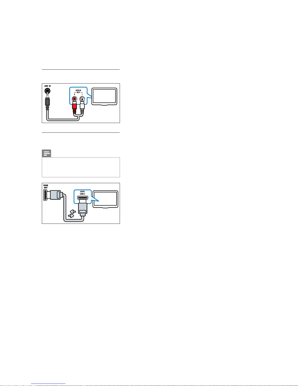
Option 2: Connect audio through
analog audio cables
Option 3: Connect audio through an
HDMI cable
Note
The HDMI connector on the TV might be
labeled HDMI 1 or HDMI ARC.This feature
works with Audio Return Channel (ARC)
compatible devices only.
•
Direction of Use
7-5
 Loading...