

Philips HTS-4282 Service Manual
Home Theater DVD Player
Service
HTS4282/12
Service Manual
TABLE OF CONTENTS
. Location of PCB BdsÿVersion Variation and Repair Scenario Matrix..........1-2
. Technical Specifications…………....………………………..............1-
. Safety Instruction, Warning & Notes….……………………....….....1-
. DFU Instruction..............................................................................2-1
. Mechanical and Dismantling Instructions…………........................3-1
. Software Upgrades .......................................................................
. Trouble Shooting Chart………………………………………………
. Wiring Diagram………………………………………..………..….….6-1
. Electrical Diagrams and Print-layouts..….…………………....….…7-1
. Set Mechanical Exploded view & Part list.…………………..….….8-1
. Revision List..................................................................................9-1
©Copyright 2011 Philips Consumer Electronics B.V. Eindhoven, The Netherlands
All rights reserved. No part of this publication may be reproduced, stored in aretrieval system or
transmitted, in any form or by any means, electronic, mechanical, photocopying, or otherwise
without the prior permission of Philips.
Page
3
4
4-1
.
5-1
.
CLASS 1
LASER PRODUCT
Published by RY&WL - 1122 BU AVM Printed in The Netherlands Subject to modification
Version 1.0
PHILIPS
GB
3139 785 35780
1-2
Amplifier Board
Karaoke and USB Board
Aux Input Board
Loader
Main Board
Power Board
Front Control Board
Touch Board
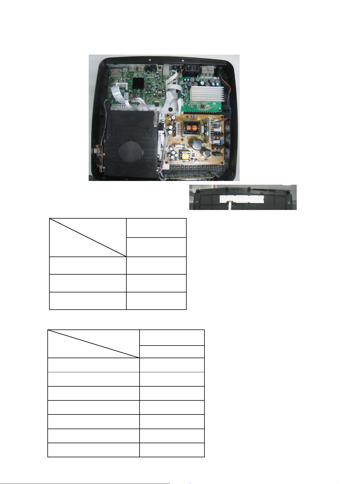
PCB BOARD LOCATION:
Version Variation
Type/Versions
Features
Output Power- 400W X
Voltage(220~240V) X
MP3 LINK X
HTS4282
/12
Repair Scenario Matrix
Type/Versions
Board in used
Main Board C
HTS4282
/12
Front Control Board C
Amplifier Board C
Power Board C
Karaoke and USB Board B
Touch Board B
Aux Input Board B
*Bd:Board Level Replacement
*C:Component Level Repair
Specification for HTS4282/12 :
1-3
Product Specifications:
Note
•
6SHFLÀFDWLRQVDQGGHVLJQDUHVXEMHFWWRFKDQJH
without notice.
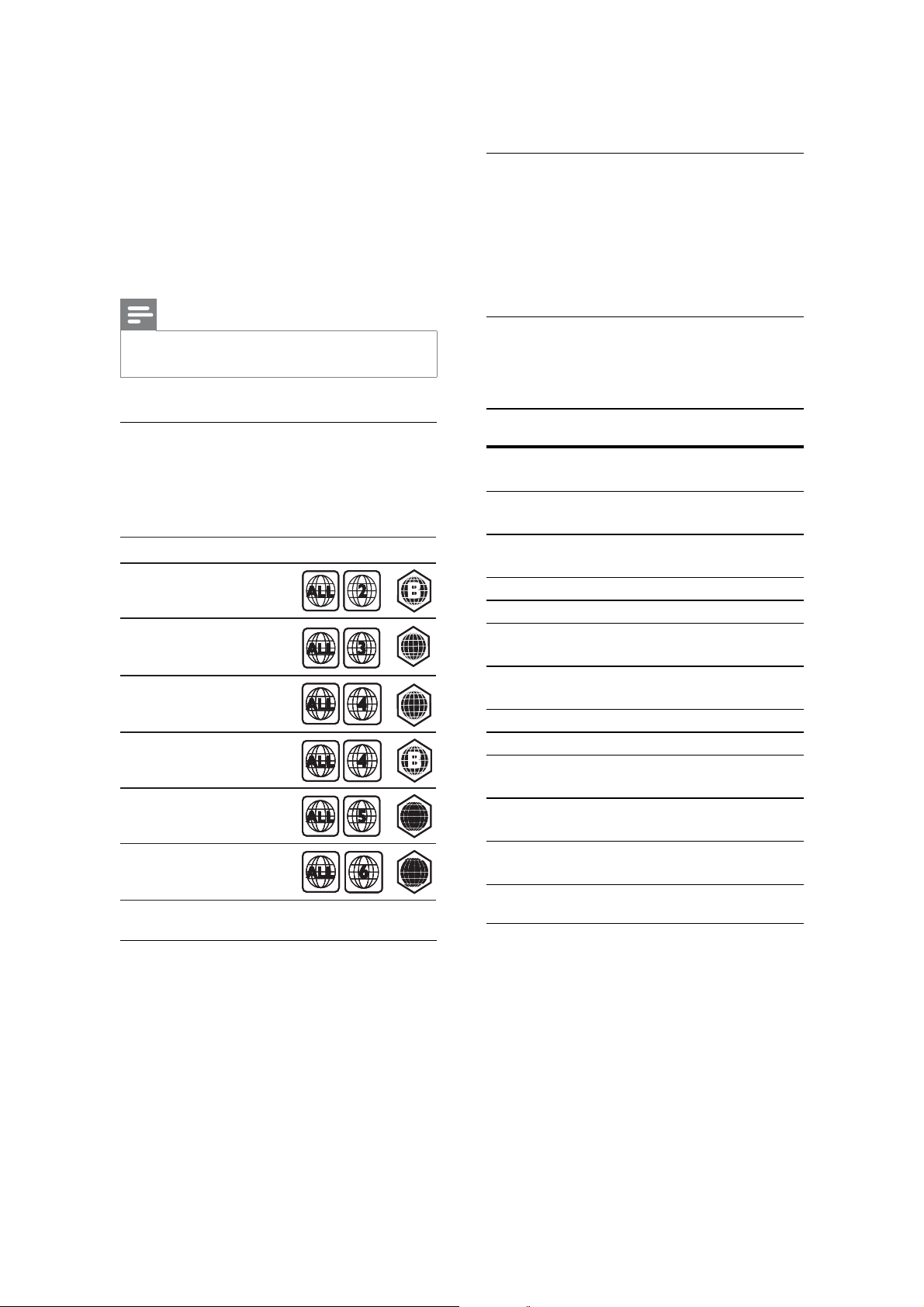
Region codes
Thetypeplateonthebackorbottomof
thehometheatershowswhichregionsit
supports.
Country
Country
Europe,
Europe,
United Kingdom
United Kingdom
Asia Pacific, Taiwan,
Asia Pacific, Taiwan,
Korea
Korea
Latin America
Latin America
Australia,
Australia,
New Zealand
New Zealand
Russia, India
Russia, India
China
China
DVD BD
DVD BD
AA
AA
AA
AA
CC
CC
CC
CC
File formats
Audio:.aac,.mka,.mp3,.wma,.wav,.mp4,
•
.m4a
Video:.avi,.divx,.mp4,.mkv,.asf,.wmv,
•
.mpg, .mpeg,
Picture: .jpg, .jpeg, .gif, .png
•
Audio formats
Your home theater supports the following
DXGLRÀOHV
Extension Container Audio
codec
.mp3 MP3 MP3 32 kbps ~
.wma ASF :0$ 64 kbps ~
.aac AAC $$&+(
AAC
.wav :$9 PCM 1.4 Mbps
.m4a MKV AAC 192 kbps
.mka MKA PCM 27.648
.mka MKA Dolby
Digital
.mka MKA DTS core 1.54 Mbps
.mka MKA MPEG 912 kbps
.mka MKA MP3 32 kbps ~
.mka MKA :0$ 64 kbps ~
.mka MKA $$&+(
AAC
Bit rate
320 kbps
160 kbps
192 kbps
Mbps
640 kbps
320 kbps
160 kbps
192 kbps
Media formats
$9&+'%'%'5%'5(%'9LGHR
•
'9'9LGHR'9'55:'9'5
5:'9'55'/&'5&'5:
$XGLR&'9LGHR&'69&'3LFWXUHÀOHV
03PHGLD:0$PHGLD'LY;3OXV+'
media, USB storage device
Video formats
,I\RXKDYHDKLJKGHÀQLWLRQ79\RXUKRPH
WKHDWHUDOORZV\RXWRSOD\\RXUYLGHRÀOHV
with:
•
Resolution: 1920 x 1080 pixels at
•
Framerate:6~ 30framespersecond.
DYLÀOHVLQ$9,FRQWDLQHU

1-4
Audio
codec
PCM,
Dolby
Digital,
Video codec Bit rate
DivX 3.11, DivX 4.
10 Mbps max
x, DivX 5.x,
DivX 6.x
DTS
core,
MP3,
:0$
MPEG 1, MPEG 2 20 Mbps (peak
40 Mbps)
MPEG4ASP 10Mbpsmax
H.264/AVC
+3#
20 Mbps (peak
40 Mbps)
MP@3.2/3.1/3.0
:09 20 Mbps
GLY[ÀOHVLQ$9,FRQWDLQHU
Audio
codec
PCM,
Dolby
Digital,
Video codec Bit rate
DivX 3.11, DivX 4.
10 Mbps max
x, DivX 5.x,
DivX 6.x
MP3,
:0$
MPEG 1, MPEG 2 20 Mbps
(peak 40
Mbps)
MPEG4ASP 10Mbpsmax
PSRUPYÀOHVLQ03FRQWDLQHU
Audio
codec
Dolby
Digital,
Video codec Bit rate
MPEG 1, MPEG220 Mbps (peak
40 Mbps)
MPEG,
MP3,
AAC,
+($$&
MPEG4ASP 10Mbpsmax
H.264/AVC
+3#
20 Mbps (peak
40 Mbps)
MP@3.2/3.1/3.0
PNYÀOHVLQ0.9FRQWDLQHU
Audio codec Video codec Bit rate
PCM,
Dolby
MPEG 1, MPEG220 Mbps (peak
40 Mbps)
Digital,
DTS core,
MPEG,
MP3,
:0$
$$&+(
AAC
MPEG4ASP 10Mbpsmax
H.264/AVC
+3#
20 Mbps (peak
40 Mbps)
MP@3.2/3.1/3.0
:09 20 Mbps
DVIDQGZPYÀOHVLQ$6)FRQWDLQHU
Audio
codec
PCM,
Video codec Bit rate
MPEG4ASP 10Mbpsmax
Dolby
Digital,
MP3,
:0$
H.264/AVC
+3#
20 Mbps (peak
40 Mbps)
MP@3.2/3.1/3.0
:09 20 Mbps
PSJDQGPSHJÀOHVLQ36FRQWDLQHU
Audio
codec
PCM,
DTS core,
Video codec Bit rate
MPEG 1,
MPEG 2
20 Mbps (peak 40
Mbps)
MPEG,
MP3
MPEG 1,
MPEG 2
20 Mbps (peak 40
Mbps)
$PSOLÀHU
7RWDORXWSXWSRZHU:506
•
THD)

•
)UHTXHQF\UHVSRQVH+]N+]
dB
•
6LJQDOWRQRLVHUDWLR!G%&&,5
$ZHLJKWHG
•
Input sensitivity:
•
AUX1,AUX2:2V
•
MusiciLink:1V
Video
•
Signalsystem:PAL/NTSC
•
HDMI output: 480i/576i, 480p/576p,
720p, 1080i, 1080p, 1080p24
1-5
Main unit
Power supply:
•
(XURSH&KLQD5XVVLD,QGLD
•
V~,50Hz
/DWLQ$PHULFD$VLD3DFLÀF
•
99a+]
3RZHUFRQVXPSWLRQ:
•
6WDQGE\SRZHUFRQVXPSWLRQ:
•
'LPHQVLRQV:[+['[[
•
mm
•
:HLJKWNJ
Subwoofer
Audio
•
S/PDIF Digital audio input:
•
&RD[LDO,(&
•
Optical: TOSLINK
•
Sampling frequency:
•
MP3: 32 kHz, 44.1 kHz, 48 kHz
•
:0$N+]N+]
•
Constant bit rate:
•
03NESVNESV
•
:0$NESVNESV
Radio
•
Tuning range:
•
(XURSH5XVVLD&KLQD)0
MHz (50 kHz)
•
$VLD3DFLÀF/DWLQ$PHULFD)0
108 MHz (50/100 kHz)
•
6LJQDOWRQRLVHUDWLR)0G%
•
)UHTXHQF\UHVSRQVH)0+]N+]
G%
USB
•
2XWSXWSRZHU:5067+'
•
Impedance: 3 ohm
•
Speakerdrivers:165mm(6.5”)woofer
•
'LPHQVLRQV:[+['[[
mm
•
:HLJKWNJ
•
Cable length: 3 m
Speakers
•
2XWSXWSRZHU[:506
THD)
•
Speakerimpedance:6ohm
•
Speakerdrivers:1x76.2mm(3”)full
range woofer
•
'LPHQVLRQV:[+['[[PP
•
:HLJKWNJHDFK
•
Cable length: 4 m
Dock for iPod/iPhone
•
Dimensions (HxD): 34.5 x 104 mm
•
:HLJKWJ
•
&RPSDWLELOLW\+L6SHHG86%
•
Class support: USB Mass Storage Class
(MSC)
•
Filesystem:FAT16,FAT32,NTFS
•
Maximummemorysupport:<160GB
Remote control batteries
•
[$$$59
Laser
•
LaserType(Diode):InGaN/AIGaN(BD),
AIGaInP (DVD/CD)
:DYHOHQJWKQPQP%'
•
QPQP'9'QP
nm (CD)
2XWSXWSRZHU0D[UDWLQJVP:
•
%'P:'9'P:&'

1-6
Safety instruction, Warning & Notes
Safety instruction
1. General safety
Safety regulations require that during a repair:
. Connect the unit to the mains via an isolation transformer.
. Replace safety components indicated by the symbol
only by components identical to the original ones. Any
other component substitution (other than original type)
may increase risk of fire or electrical shock hazard.
Safety regulations require that after a repair, you must
return the unit in its original condition. Pay, in particular,
attention to the following points:
. Route the wires/cables correctly, and fix them with the
mounted cable clamps.
. Check the insulation of the mains lead for external
damage.
. Check the electrical DC resistance between the mains
plug and the secondary side:
1) Unplug the mains cord, and connect a wire between
the two pins of the mains plug.
2) Set the mains switch the “on” position (keep the
mains cord unplug).
3) Measure the resistance value between the mains
plug and the front panel, controls, and chassis
bottom.
4) Repair or correct unit when the resistance
measurement is less than 1M
5) Verify this, before you return the unit to the
customer/user (ref. UL-standard no. 1492).
6) Switch the unit “off”, and remove the wire between
the two pins of the mains plug.
¡
.
2.Laser safety
This unit employs a laser. Only qualified service personnel
,
may remove the cover, or attempt to service this device
(due to possible eye injury).
Laser device unit
Type : Semiconductor laser GaAlAs
Wavelength : 650nm (DVD)
: 780nm (VCD/CD)
Output power : 7mW (DVD)
: 10mW (DVD /CD)
Beam divergence: 60 degree
Note: Use of controls or adjustments or performance of
procedure other than those specified herein, may result in
hazardous radiation exposure. Avoid direct exposure to
beam.

Warning
1-7
1.General
. All ICs and many other semiconductors are susceptible to
electrostatic discharges (ESD). Careless handing during
repair can reduce life drastically. Make sure that, during
repair, you are at the same potential as the mass of the
set by a wristband with resistance. Keep components and
tools at this same potential. Available ESD protection
equipment:
1) Complete kit ESD3 (small tablemat, wristband,
connection box, extension cable and earth cable)
4822 310 10671.
2) Wristband tester 4822 344 13999.
. Be careful during measurements in the live voltage
section. The primary side of the power supply , including
the heat sink, carries live mains voltage when you
connect the player to the mains (even when the player is
“off”!). It is possible to touch copper tracks and/or
components in this unshielded primary area, when you
service the player. Service personnel must take
precautions to prevent touching this area or components
in this area. A “lighting stroke” and a stripe-marked
printing on the printed wiring board, indicate the primary
side of the power supply.
. Never replace modules, or components, while the unit is
“on”.
2. Laser
. The use of optical instruments with this product, will
increase eye hazard.
. Only qualified service personnel may remove the cover
or attempt to service this device, due to possible eye
injury.
. Repair handing should take place as much as possible
with a disc loaded inside the player.
. Text below is placed inside the unit, on the laser cover
shield:
CAUTION: VISIBLE AND INVISIBLE LASER
RADIATION WHEN OPEN, AVOID EXPOSURE
TO BEAM.
Notes: Manufactured under licence from Dolby
Laboratories. The double-D symbol is trademarks of Dolby
Laboratories, Inc. All rights reserved.
1-8
6HUYLFH+LQWV
&$87,21
&+$5*('&$3$&,7256217+(6(592%2$5'0$<'$0$*(7+('5,9(
(/(&7521,&6:+(1&211(&7,1*$1(:'5,9(7+$7¶6:+<%(6,'(67+(6$)(7<
0($685(6/,.(
6:,7&+2))32:(56833/<
(6'3527(&7,21
$'',7,21$/$&7,2160867%(7$.(1%<7+(5(3$,57(&+1,&,$1
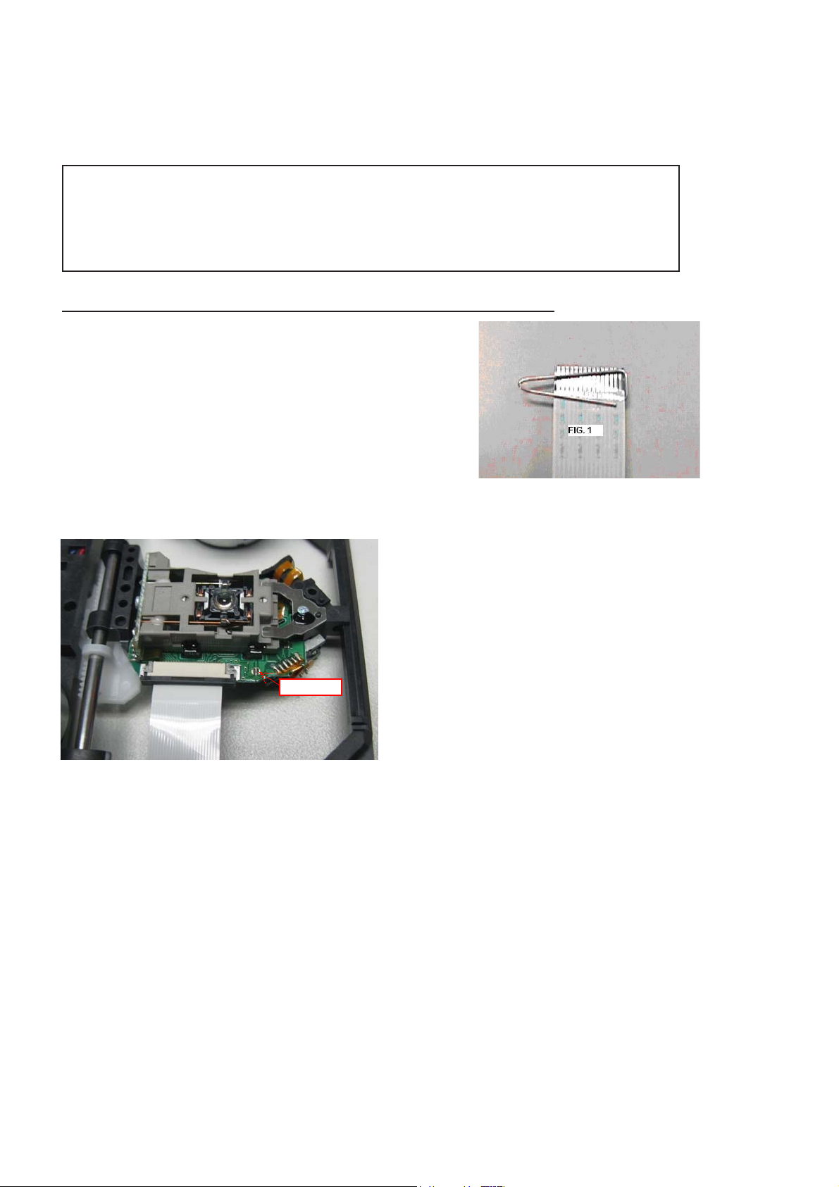
7KHIROORZLQJVWHSVKDYHWREHGRQHZKHQUHSODFLQJWKHGHIHFWLYHORDGHU
'LVPDQWOLQJRIWKHORDGHUWRDFFHVVWKH(6'SURWHFWLRQSRLQWLIQHFHVVDU\
6ROGHUWKH(6'SURWHFWLRQSRLQW
'LVFRQQHFWÀH[IRLOFDEOHIURPWKHGHIHFWLYHORDGHU
3XWDSDSHUFOLSRQWKHÀH[IRLOWRVKRUWFLUFXLWWKHFRQWDFWV¿J
5HSODFHWKHGHIHFWLYHORDGHUZLWKDQHZORDGHU
5HPRYHSDSHUFOLSIURPWKHÀH[IRLODQGFRQQHFWLWWRWKHQHZORDGHU
5HPRYHVROGHUMRLQWRQWKH(6'SURWHFWLRQSRLQW
$77(17,217KHODVHUGLRGHRIWKLVORDGHULVSURWHFWHGDJDLQVW(6'E\DVROGHUMRLQWZKLFKVKRUWFLUFXLWVWKHODVHUGLRGHWRJURXQG
)RUSURSHUIXQFWLRQDOLW\RIWKHORDGHUWKLVVROGHUMRLQWPXVWEHUHPRYHDIWHUFRQQHFWLRQORDGHUWRWKHVHW
Solder Joint
2QO\DSSOLFDEOHIRUGHIHFWLYHORDGHUQHHGHGWREHVHQWEDFNWRVXSSOLHUIRUIDLOXUHDQDO\VLVDQGWRVXSSRUWEDFNFKDUJLQJ
HYLGHQFH
7KLVLVDOVRDSSOLFDEOHIRUDOOSDUWQHUVKLSZRUNVKRSV
(6'SURWHFWLRQSRLQWLVDFFHVVLEOHIURPWRSRIORDGHU

Notes
Lead-Free requirement for service
1-9
INDENTIFICATION:
Regardless of special logo (not always indicated)
One must treat all sets from 1.1.2005 onwards, according
next rules.
Important note: In fact also products a little older can also
be treated in this way as long as you avoid mixing
solder-alloys (leaded/ lead-free). So best to always use
SAC305 and the higher temperatures belong to this.
Due to lead-free technology some rules have to be
respected by the workshop during a repair:
x Use only lead-free solder alloy Philips SAC305 with
order code 0622 149 00106. If lead-free solder-paste is
required, please contact the manufacturer of your
solder-equipment. In general use of solder-paste within
workshops should be avoided because paste is not easy
to store and to handle.
x Use only adequate solder tools applicable for lead-free
solder alloy. The solder tool must be able
o To reach at least a solder-temperature of 400°C,
o To stabilize the adjusted temperature at the
solder-tip
o To exchange solder-tips for different applications.
x Adjust your solder tool so that a temperature around
360°C
– 380°C is reached and stabilized at the solder
joint. Heating-time of the solder-joint should not exceed
~ 4 sec. Avoid temperatures above 400°C otherwise
wear-out of tips will rise drastically and flux-fluid will be
destroyed. To avoid wear-out of tips switch off un-used
equipment, or reduce heat.
x Mix of lead-free solder alloy / parts with leaded solder
alloy / parts is possible but PHILIPS recommends
strongly to avoid mixed
solder alloy types (leaded and lead-free). If one cannot
avoid, clean carefully the
solder-joint from old solder alloy and re-solder with new
solder alloy (SAC305).
x Use only original spare-parts listed in the
Service-Manuals. Not listed standard-material
(commodities) has to be purchased at external
companies.
x Special information for BGA-ICs:
- always use the 12nc-recognizable soldering
temperature profile of the specific BGA (for
de-soldering always use highest lead-free
temperature profile, in case of doubt)
- lead free BGA-ICs will be delivered in so-called
‘dry-packaging’ (sealed pack including a silica gel
pack) to protect the IC against moisture. After
opening, dependent of MSL-level seen on
indicator-label in the bag, the BGA-IC possibly
still has to be baked dry. This will be
communicated via AYS-website.
Do not re-use BGAs at all.
x For sets produced before 1.1.2005, containing
leaded soldering-tin and components, all needed
spare-parts will be available till the end of the
service-period. For repair of such sets nothing
changes.
x On our website:
www.atyourservice.ce.Philips.com
You find more information to:
BGA-de-/soldering (+ baking instructions)
Heating-profiles of BGAs and other ICs used in
Philips-sets
You will find this and more technical information
within the “magazine”, chapter “workshop news”.
For additional questions please contact your local
repair-helpdesk.
3-1
XP14
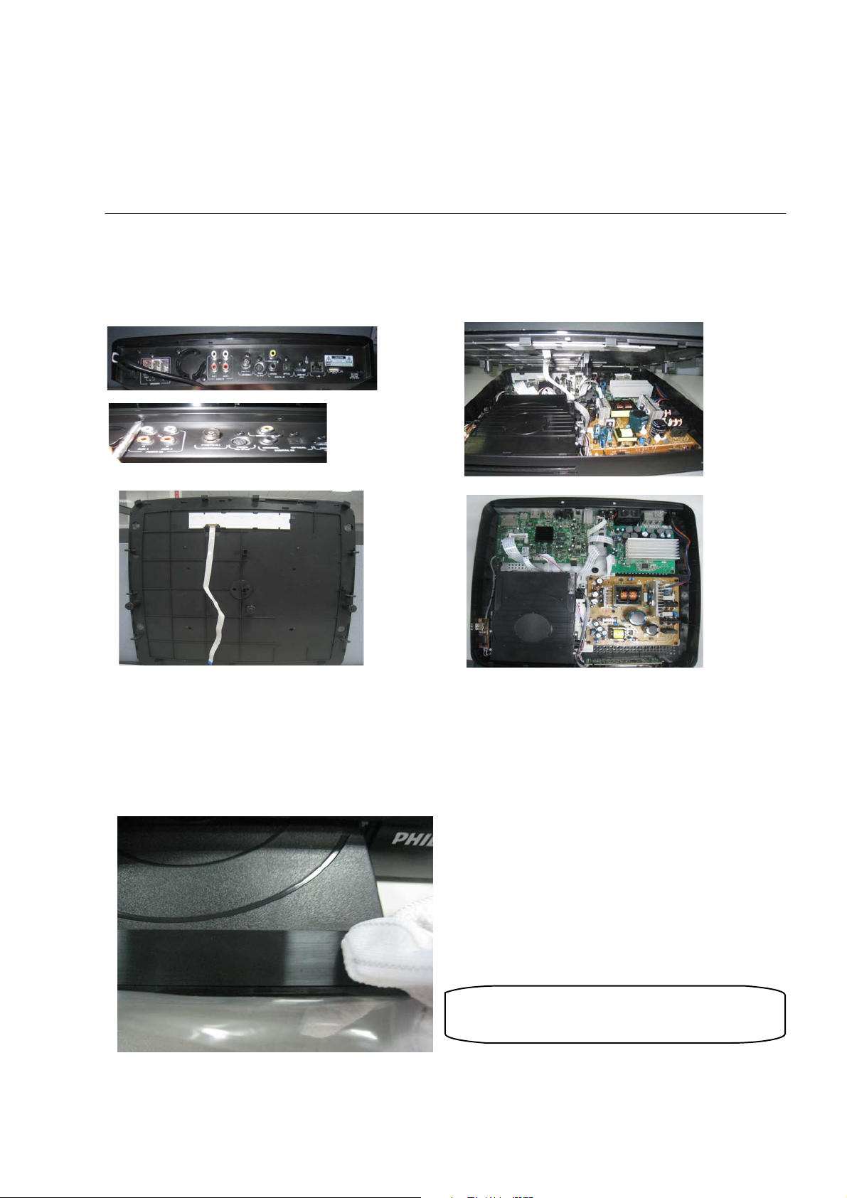
Mechanical and Dismantling Instructions
Dismantling Instruction
The following guidelines show how to dismantle the player.
Step1:
Remove 2 screws of Rear Plate, and then dismantle the Turn Knob connecting TOP COVER
and BOTTOM PLATE.Finally ,dismantle the XP14,then remove the TOP COVER (Figure 1).
Detailed information please refer to the model set.
Figure 1
: If it is necessary to dismantle Loader , the Front door should be removed first. (Figure 2)
Step2
Note: Make sure to operate gently otherwise the guider would be damaged.
Please kindly note that dismantle the front door
assembly carefully to avoid damage tray and the front door.
Figure 2
3-2
XP11
XP8
XP1
XP10
XP703
XP702
CN501
XP13
XP5
XP7
XP6
XP605
XP3
XP8
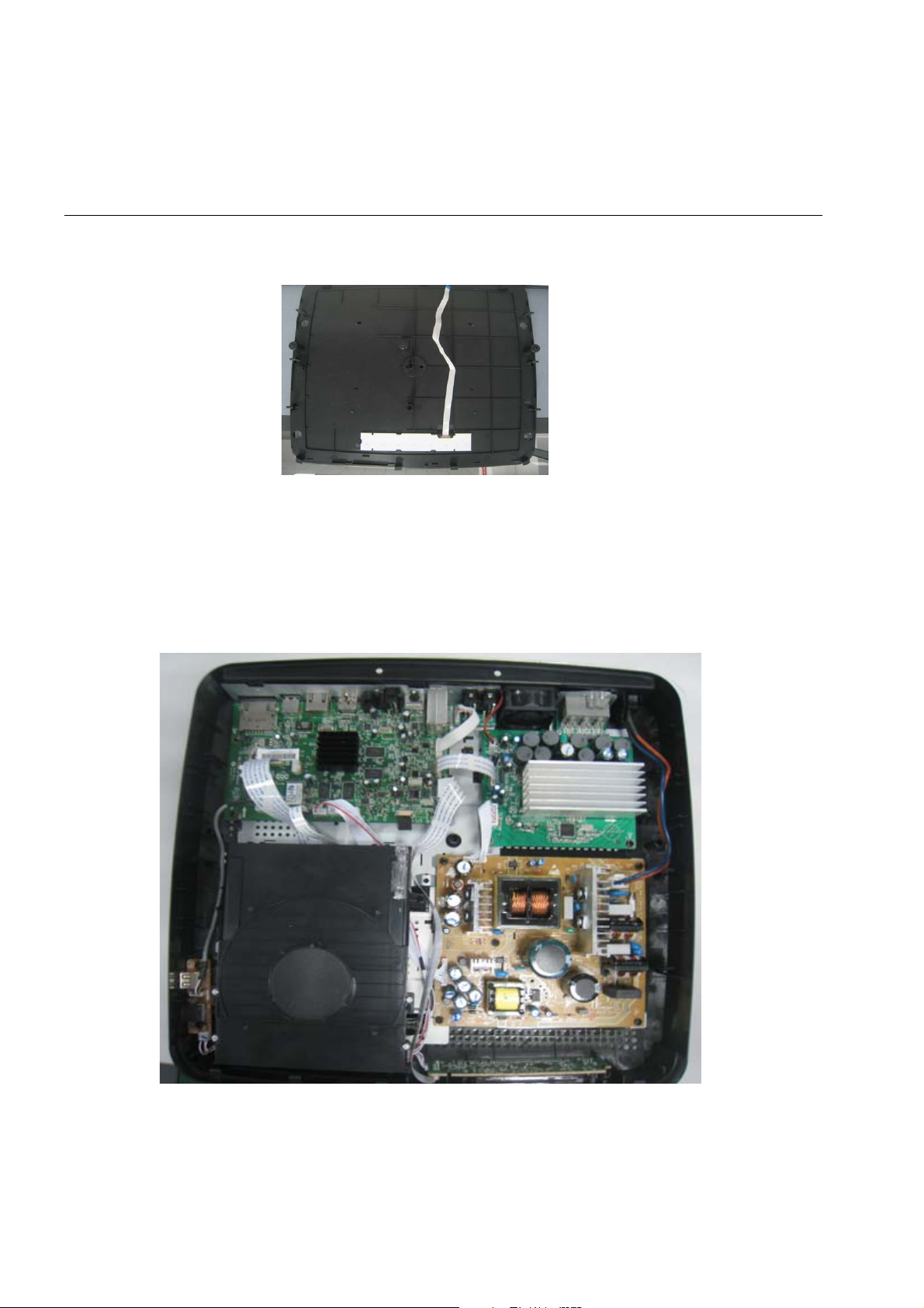
Mechanical and Dismantling Instructions
Dismantling Instruction
:Remove the white plastic Front Panel,then take the TC Board out from Assembly TOP COVER .(Figure 3)
Step3
:Dismantle Front Control Board,disconnect 2 connectors(XP605,XP3).( Figure 4)
Step4
Figure 3
:Dismantle Loader,disconnect 3 connectors(XP5,XP7,XP10) and remove 2 screws
Step5
that connects the loader and the bottom plate.(Figure 4- Figure5)
Detailed information please refer to the model set.
Figure 4
3-3
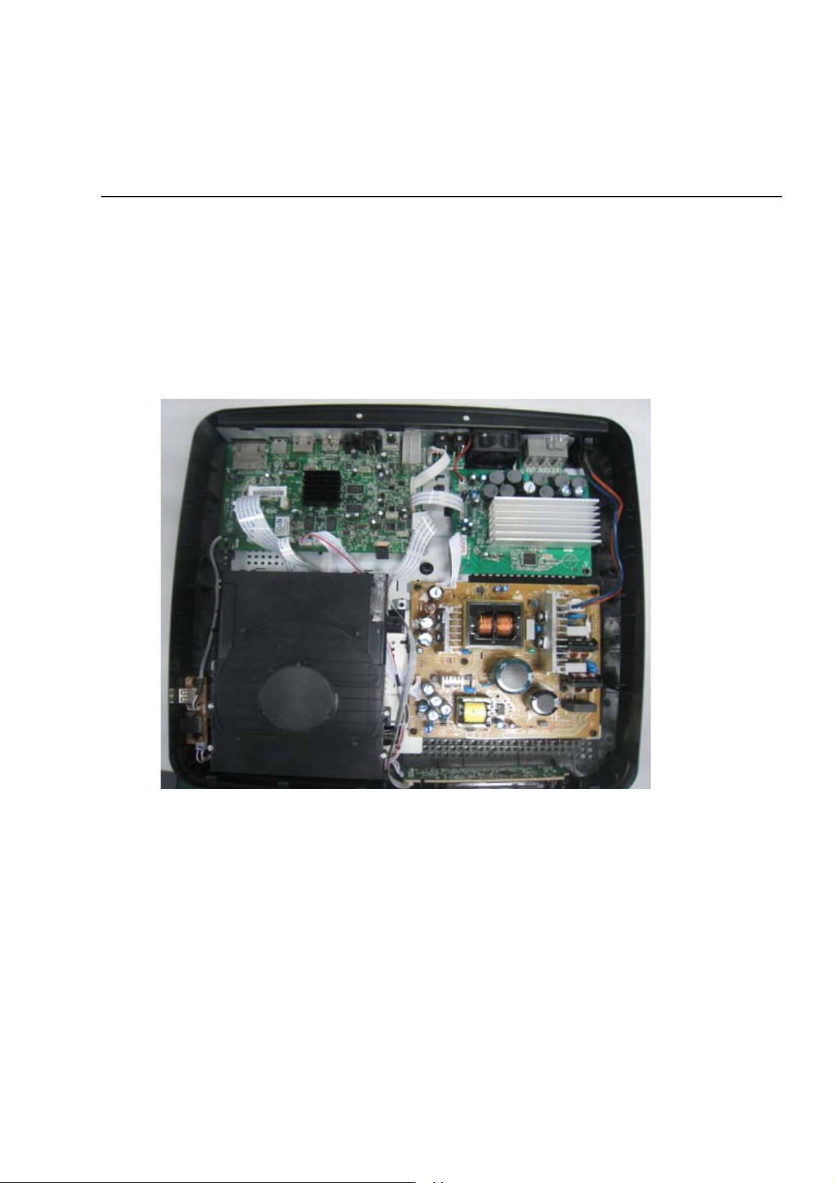
Mechanical and Dismantling Instructions
Dismantling Instruction
Step6
:Dismantle Main Board,disconnect 5 connectors(XP1,XP6,XP8,XP11,XP13) and remove 7 screws.(Figure4-Figure5)
Step7
:Dismantle Power Board,disconnect 2 connectors(XP702,CN501) and remove 5 screws.(Figure4-Figure5)
Step8
:Dismantle Amplifier Board,disconnect 2 connectors(XP8,XP703) and remove 3 screws.(Figure4-Figure5)
:Dismantle Karaoke and USB Board,remove 2 screws.(Figure4)
9
Step
:Dismantle Fan,remove 2 screws.(Figure4)
Step10
Step11
:Dismantle KUX Input Board,remove 1 screws.(Figure4)
Detailed information please refer to the model set.
Figure 5
Figure 5

4-1
Software upgrade
A. Software upgrade method:
1. Set up a new folder and name it ’UPG’ in the root of USB device.
2. Copy the file(HTS_XXXX.bin)which you want to upgrade into the ‘UPG’ folder
3. Power on the BD Player, after it shows the UI, plug the USB device
4. Select the SETUP Menu, then find and select item ‘Advanced’
5. In the item ‘Advanced’, find and select item ‘Software Update’, then select item
‘USB’, please follow the tip to complete the upgrade.
B. Read out the software versions to confirm upgrading
Follow the steps shows below:
SETUP—>Advanced >Version Info.
While it shows the dialog box, we can see some information like below:
For example:
Model:HTSxxxx/xx
System SW:x.xx.xx
Subsystem SW:xx-xx-xx-xx
Ethernet MAC:xx:xx:xx:xx:xx;xx
EUI64:xxxxxxxxxxxxxxx
Caution: The set must not be power off during
upgrading, Otherwise the Main board will be
damaged entirely.
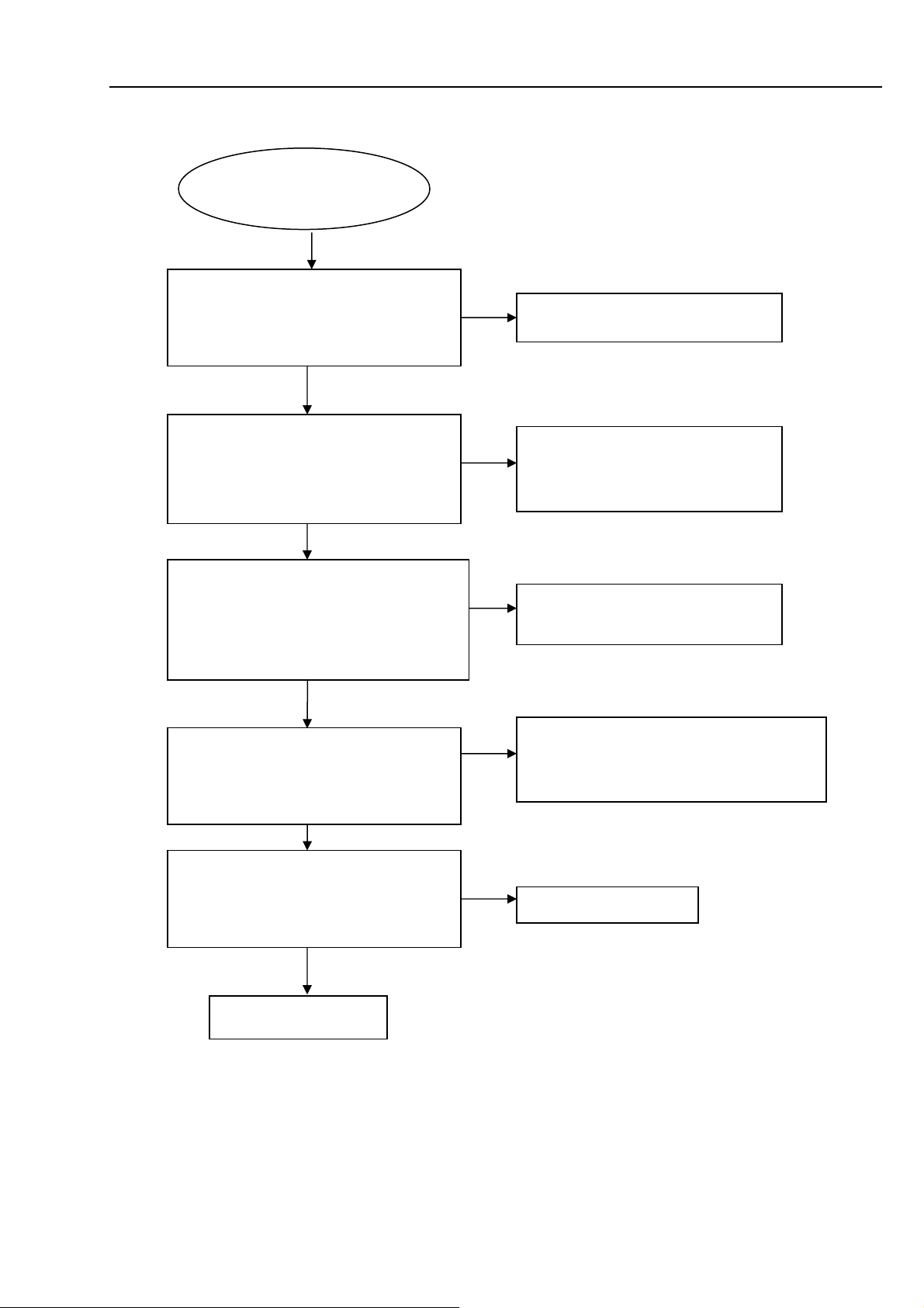
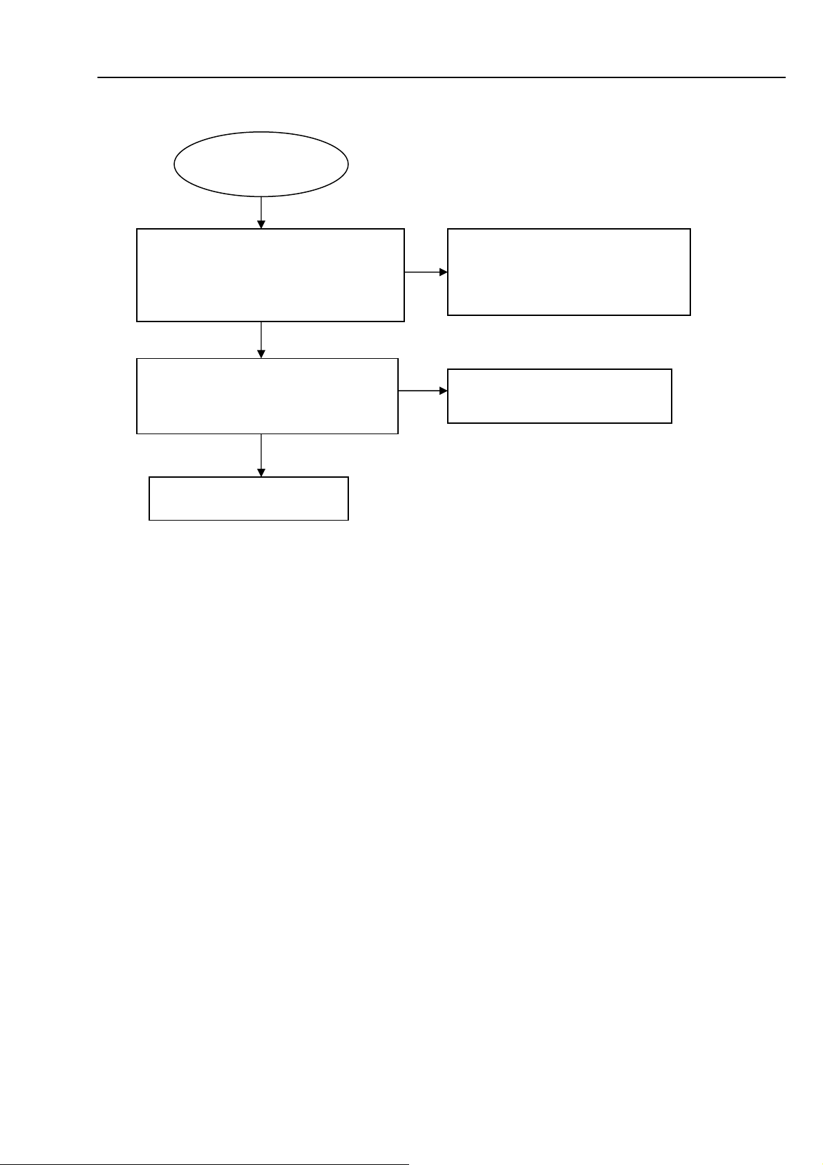
VFD No display on Front Control Board
VFD No display on
Front Control Board
Go
Check every supply voltage on Main Board
whether normal or not.
(XP8 PIN4:-24V, PIN5: 12V, PIN6: 3.3V)
Yes
Check voltage -24V, +5V,+12V on Power
Board at CN502 position and Front Control
Board( HTS4282:XP3 PIN4:-24V
PIN5:+12V PIN6:+5V)
Yes
Check the power key(HTS4282:PAD604),
open/closed key(HTS4282:PAD601), source
key(HTS4282:PAD605) on Touch Board
whether work normally or not
Yes
Check Front Control Board signals
SCL,SDA
(HTS4282:XP3 PIN1: SCL PIN2:SDA)
Yes
Check whether bad solder exists on
HTS4282:XP3 on Front Control Board and
VFD135 of VFD,
Yes
Replace U135 or VFD
5-1 Trouble shooting Chart
No
Refer to CN502 on Power Board
No
Fix the connection HTS4282:XP3 on
Front Control Board and XP8 on
Main Board
No
Replace U4 on Main Board d, or
replace the Main Board
No
HTS4282:
PIN2 PIN3 arrive the condition U4 PIN38
PIN39
No
Correct connection
Check the XP14 ON Main Board
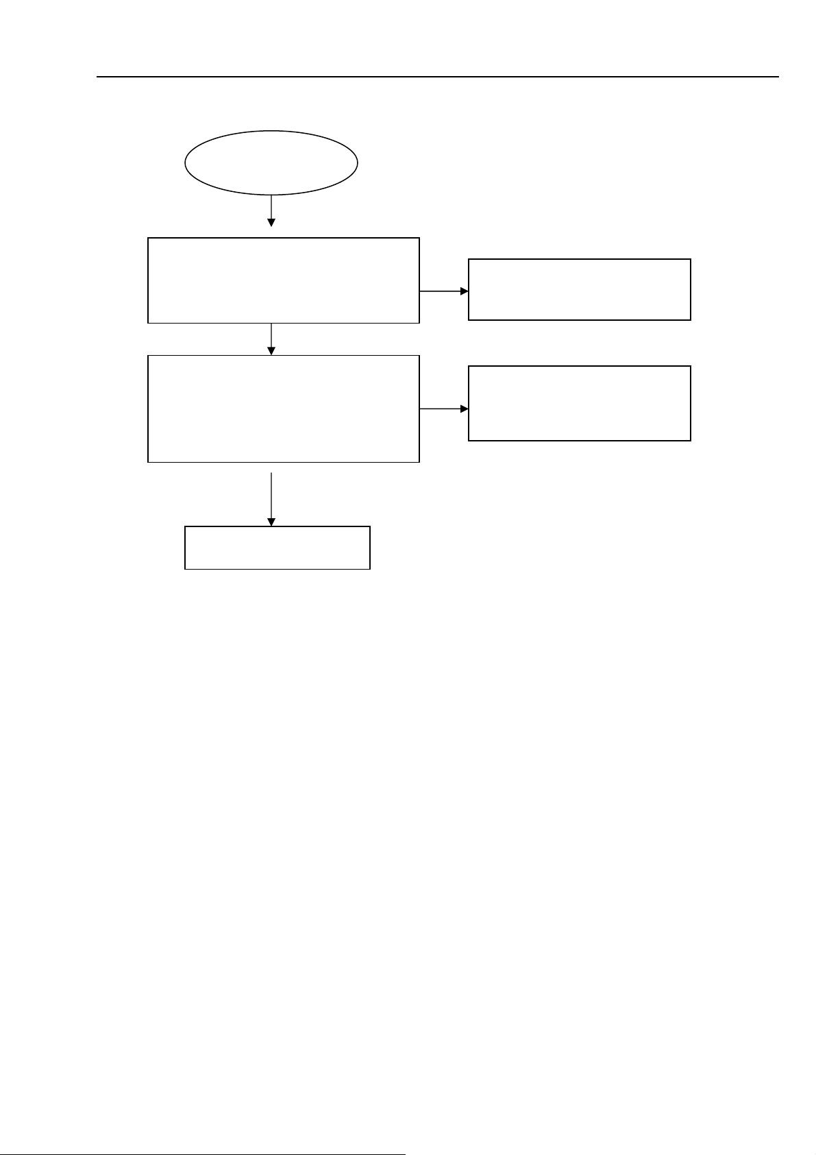
Touch keys do not work
Touch keys do not
work
Check voltage +3.3V on Touch Board
HTS4282:(XP601 PIN1)
and Main Board (XP14 PIN1)
Go
Yes
Check Front Control Board and Touch
Board signals SCL(TOUCH Board U603
PIN19),SDA(U603 PIN18)
Yes
Replace Touch Board
on Touch Board
5-2 Trouble shooting Chart
No
No
HTS4282: Fix the connection XP601
on Touch Board and XP14 on Main
Board
Replace U4 on Main Board, or
replace Main Board
Remote control does not work
Remote control
does not work
Go
Check battery of remote control whether
exhausted or not.
Check power supply of IR601 on Front
Control Board whether normal or not
HTS4282:XP3 PIN9 3.3V
No
Yes
Replace IR601
5-3 Trouble shooting Chart
Yes
No
Replace the battery for remote
control
Check the +3.3V net on Front
Control Board HTS4282:XP3
 Loading...