

Page 1

Home Theater BD Player
Second Generation
Service
HTS3592/93
TABLE OF CONTENTS
Location of PCB Boards & version variation & repair scenario matrix.....................
Production Speci cations ...............................................................................................1-3
Safety Instruction, Warning & Notes................................................................................1-
D Instruction................................................................................................................2-1
FU
Mechanical and Dismantling Instructions ........................................................................3-1
Software Upgrades........................................................................................................... -1
Trouble Shooting Chart .................................................................................................... -1
Wiring Diagrams ................................................................................................6-1
Electrical Diagrams and Print-layouts .................................................................7-1
Set Mechanical Exploded view ....................................................................................... -1
Revision List .................................................................................................................
This service manual is for HTS3592 Second Generation model,
which is different from the previous generation HTS3592/93
model.
For Second Generation model the serial number begin with
KX2AXXXXXXXXXX.Refer to the rating lable illustration at right.
©
Copyright 2010 Philips Consumer Electronics B.V. Eindhoven, The Netherlands
All rights reserved. No part of this publication may be reproduced, stored in a retrieval system or
transmitted, in any form or by any means, electronic, mechanical, photocopying, or otherwise without
the prior permission of Philips.
Published by Helen-RY 1207 Service Audio Printed in The Netherlands Subject to modification
Page
1-2
6
4
5
8
..
9
-1
CLASS 1
LASER PRODUCT
GB
GB
313978536101
©
Version 1.
Version 1.1
Version 0.0
Page 2

A
1-2
PCB BOARD LOCATION:
MAIN BOARD
LOADER
MPLIFIER BOARD
POWER BOARD
Version Variation
Type/Versions
HTS3592M2
Features
/93
Power supply rating:220-240V ,50Hz X
Power consumption:110W X
Repair Scenario Matrix
Type/Versions
Board in used
Main Board C
Front Control Board C
HTS3592M2
/93
Amplifier Board C
Power Board C
*Bd:Board Level Replacement
*C:Component Level Repair
Page 3
1-3
HTS3592M2/93
Product Specifications:
Note
Specifi cations and design are subject to change
•
without notice.
Region codes
The type plate on the back or bottom of the
home theater shows which regions it supports.
Country
China
DVD BD
Media formats
•
AVCHD, BD, BD-R/ BD-RE, BD-Video,
DVD-Video, DVD+R/+RW, DVD-R/-RW,
DVD+R/-R DL, CD-R/CD-RW, Audio CD,
Video CD/SVCD, Picture fi les, MP3 media,
WMA media, DivX Plus HD media, USB
storage device
RMVB (Available only in Asia Pacifi c and China)
•
CC
Video
Signal system: PAL / NTSC
•
•
HDMI output: 480i/576i, 480p/576p, 720p,
1080i, 1080p, 1080p24
Audio
•
S/PDIF Digital audio input:
Coaxial: IEC 60958-3
•
•
Optical: TOSLINK
•
Sampling frequency:
MP3: 32 kHz, 44.1 kHz, 48 kHz
•
•
WMA: 44.1 kHz, 48 kHz
Constant bit rate:
•
•
MP3: 32 kbps - 320 kbps
• WMA: 48 kbps - 192 kbps
Radio
•
Tuning range:
•
Europe/Russia/China: FM 87.5-108 MHz
(50 kHz)
•
Asia Pacifi c/Latin America: FM 87.5-108
MHz (50/100 kHz)
Signal-to-noise ratio: FM > 45 dB
•
Frequency response: FM 180 Hz-12.5 kHz /
•
±3 dB
USB
File formats
•
Audio: .aac, .mka, .mp3, .wma, .wav, .mp4, .m4a
Video:
•
•
.avi, .divx, .mp4, .mkv, .asf, .wmv, .mpg,
.mpeg,
• .rmvb, .rm (Available only in Asia Pacifi c
and China)
•
Picture: .jpg, .jpeg, .gif, .png
Amplifi er
•
Total output power: 600W RMS (30% THD)
•
Frequency response: 20 Hz-20 kHz / ±3 dB
Signal-to-noise ratio: > 65 dB (CCIR) /
•
(A-weighted)
Input sensitivity:
•
AUX: 2 V
•
•
Music iLink: 1 V
• Compatibility: Hi-Speed USB (2.0)
Class support: USB Mass Storage Class
•
(MSC)
•
File system: FAT16, FAT32, NTFS
Maximum memory suppor t: < 160 GB
•
Main unit
Power supply: 220-240 V~, 50 Hz
•
Power consumption: 110 W
•
Standby power consumption: 0.9 W - 0.5 W
•
•
Dimensions (WxHxD): 360 x 58 x 325 mm
Weight: 2.62 kg
•
Subwoofer
Output power: 100 W RMS (30% THD)
•
Impedance: 4 ohm
•
Speaker drivers: 133 mm (5.25") woofer
•
Dimensions (WxHxD): 160 x 267.5 x 265
•
mm
Weight: 2.55 kg
•
Page 4

Speakers
Center speaker:
• Output power: 100 W RMS (30% THD)
Speaker impedance: 4 ohm
•
Speaker drivers: 1 x 63.5 mm (2.5") woofer
•
Dimensions (WxHxD): 160 x 85 x 95 mm
•
•
Weight: 0.37 kg
Front/Rear speaker:
•
Output power: 4 x 100 W RMS (30% THD)
•
Speaker impedance: 4 ohm
•
Speaker drivers: 1 x 76.2 mm (3") twin driver
•
Dimensions (WxHxD):
Speakers: 85 x 160 x 95mm
•
• Tall speakers: 240 x 1007 x 240 mm
Weight:
•
Speakers: 0.35 kg/each
•
Tall speakers: 1.57 kg/each
•
1-4
Remote control batteries
•
2 x AAA-R03-1.5 V
Laser
Laser Type (Diode): InGaN/AIGaN (BD),
•
AIGaInP (DVD/CD)
•
Wave length: 405 +7 nm/-7 nm (BD), 655
+10 nm/-10 nm (DVD), 790 +10 nm/-20 nm
(CD)
Output power (Max. ratings): 20 mW (BD), 6
•
mW (DVD), 7 mW (CD)
Page 5

1-5
Safety instruction, Warning & Notes
Safety instruction
1. General safety
Safety regulations require that during a repair:
. Connect the unit to the mains via an isolation transformer.
. Replace safety components indicated by the symbol
only by components identical to the original ones. Any
other component substitution (other than original type)
may increase risk of fire or electrical shock hazard.
Safety regulations require that after a repair, you must
return the unit in its original condition. Pay, in particular,
attention to the following points:
. Route the wires/cables correctly, and fix them with the
mounted cable clamps.
. Check the insulation of the mains lead for external
damage.
. Check the electrical DC resistance between the mains
plug and the secondary side:
1) Unplug the mains cord, and connect a wire between
the two pins of the mains plug.
2) Set the mains switch the “on” position (keep the
mains cord unplug).
3) Measure the resistance value between the mains
plug and the front panel, controls, and chassis
bottom.
4) Repair or correct unit when the resistance
measurement is less than 1M
5) Verify this, before you return the unit to the
customer/user (ref. UL-standard no. 1492).
6) Switch the unit “off”, and remove the wire between
the two pins of the mains plug.
¡
.
2.Laser safety
This unit employs a laser. Only qualified service personnel
,
may remove the cover, or attempt to service this device
(due to possible eye injury).
Laser device unit
Type : Semiconductor laser GaAlAs
Wavelength : 650nm (DVD)
: 780nm (VCD/CD)
Output power : 7mW (DVD)
: 10mW (DVD /CD)
Beam divergence: 60 degree
Note: Use of controls or adjustments or performance of
procedure other than those specified herein, may result in
hazardous radiation exposure. Avoid direct exposure to
beam.
Page 6

Warning
1-6
1.General
. All ICs and many other semiconductors are susceptible to
electrostatic discharges (ESD). Careless handing during
repair can reduce life drastically. Make sure that, during
repair, you are at the same potential as the mass of the
set by a wristband with resistance. Keep components and
tools at this same potential. Available ESD protection
equipment:
1) Complete kit ESD3 (small tablemat, wristband,
connection box, extension cable and earth cable)
4822 310 10671.
2) Wristband tester 4822 344 13999.
. Be careful during measurements in the live voltage
section. The primary side of the power supply , including
the heat sink, carries live mains voltage when you
connect the player to the mains (even when the player is
“off”!). It is possible to touch copper tracks and/or
components in this unshielded primary area, when you
service the player. Service personnel must take
precautions to prevent touching this area or components
in this area. A “lighting stroke” and a stripe-marked
printing on the printed wiring board, indicate the primary
side of the power supply.
. Never replace modules, or components, while the unit is
“on”.
2. Laser
. The use of optical instruments with this product, will
increase eye hazard.
. Only qualified service personnel may remove the cover
or attempt to service this device, due to possible eye
injury.
. Repair handing should take place as much as possible
with a disc loaded inside the player.
. Text below is placed inside the unit, on the laser cover
shield:
CAUTION: VISIBLE AND INVISIBLE LASER
RADIATION WHEN OPEN, AVOID EXPOSURE
TO BEAM.
Notes: Manufactured under licence from Dolby
Laboratories. The double-D symbol is trademarks of Dolby
Laboratories, Inc. All rights reserved.
Page 7

1-7
6HUYLFH+LQWV
&$87,21
&+$5*('&$3$&,7256217+(6(592%2$5'0$<'$0$*(7+('5,9(
(/(&7521,&6:+(1&211(&7,1*$1(:'5,9(7+$7¶6:+<%(6,'(67+(6$)(7<
0($685(6/,.(
6:,7&+2))32:(56833/<
(6'3527(&7,21
$'',7,21$/$&7,2160867%(7$.(1%<7+(5(3$,57(&+1,&,$1
7KHIROORZLQJVWHSVKDYHWREHGRQHZKHQUHSODFLQJWKHGHIHFWLYHORDGHU
'LVPDQWOLQJRIWKHORDGHUWRDFFHVVWKH(6'SURWHFWLRQSRLQWLIQHFHVVDU\
6ROGHUWKH(6'SURWHFWLRQSRLQW
'LVFRQQHFWÀH[IRLOFDEOHIURPWKHGHIHFWLYHORDGHU
3XWDSDSHUFOLSRQWKHÀH[IRLOWRVKRUWFLUFXLWWKHFRQWDFWV¿J
5HSODFHWKHGHIHFWLYHORDGHUZLWKDQHZORDGHU
5HPRYHSDSHUFOLSIURPWKHÀH[IRLODQGFRQQHFWLWWRWKHQHZORDGHU
5HPRYHVROGHUMRLQWRQWKH(6'SURWHFWLRQSRLQW
$77(17,217KHODVHUGLRGHRIWKLVORDGHULVSURWHFWHGDJDLQVW(6'E\DVROGHUMRLQWZKLFKVKRUWFLUFXLWVWKHODVHUGLRGHWRJURXQG
)RUSURSHUIXQFWLRQDOLW\RIWKHORDGHUWKLVVROGHUMRLQWPXVWEHUHPRYHDIWHUFRQQHFWLRQORDGHUWRWKHVHW
Solder Joint
2QO\DSSOLFDEOHIRUGHIHFWLYHORDGHUQHHGHGWREHVHQWEDFNWRVXSSOLHUIRUIDLOXUHDQDO\VLVDQGWRVXSSRUWEDFNFKDUJLQJ
HYLGHQFH
7KLVLVDOVRDSSOLFDEOHIRUDOOSDUWQHUVKLSZRUNVKRSV
(6'SURWHFWLRQSRLQWLVDFFHVVLEOHIURPWRSRIORDGHU
Page 8

Notes
Lead-Free requirement for service
1-8
INDENTIFICATION:
Regardless of special logo (not always indicated)
One must treat all sets from 1.1.2005 onwards, according
next rules.
Important note
be treated in this way as long as you avoid mixing
solder-alloys (leaded/ lead-free). So best to always use
SAC305 and the higher temperatures belong to this.
Due to lead-free technology some rules have to be
respected by the workshop during a repair:
x Use only lead-free solder alloy Philips SAC305 with
order code 0622 149 00106. If lead-free solder-paste is
required, please contact the manufacturer of your
solder-equipment. In general use of solder-paste within
workshops should be avoided because paste is not easy
to store and to handle.
x Use only adequate solder tools applicable for lead-free
solder alloy. The solder tool must be able
x Adjust your solder tool so that a temperature around
360°C
joint. Heating-time of the solder-joint should not exceed
~ 4 sec. Avoid temperatures above 400°C otherwise
wear-out of tips will rise drastically and flux-fluid will be
destroyed. To avoid wear-out of tips switch off un-used
equipment, or reduce heat.
x Mix of lead-free solder alloy / parts with leaded solder
alloy / parts is possible but PHILIPS recommends
strongly to avoid mixed
solder alloy types (leaded and lead-free). If one cannot
avoid, clean carefully the
solder-joint from old solder alloy and re-solder with new
solder alloy (SAC305).
: In fact also products a little older can also
o To reach at least a solder-temperature of 400°C,
o To stabilize the adjusted temperature at the
solder-tip
o To exchange solder-tips for different applications.
– 380°C is reached and stabilized at the solder
x Use only original spare-parts listed in the
Service-Manuals. Not listed standard-material
(commodities) has to be purchased at external
companies.
x Special information for BGA-ICs:
- always use the 12nc-recognizable soldering
temperature profile of the specific BGA (for
de-soldering always use highest lead-free
temperature profile, in case of doubt)
- lead free BGA-ICs will be delivered in so-called
‘dry-packaging’ (sealed pack including a silica gel
pack) to protect the IC against moisture. After
opening, dependent of MSL-level seen on
indicator-label in the bag, the BGA-IC possibly
still has to be baked dry. This will be
communicated via AYS-website.
Do not re-use BGAs at all.
x For sets produced before 1.1.2005, containing
leaded soldering-tin and components, all needed
spare-parts will be available till the end of the
service-period. For repair of such sets nothing
changes.
x On our website:
www.atyourservice.ce.Philips.com
You find more information to:
BGA-de-/soldering (+ baking instructions)
Heating-profiles of BGAs and other ICs used in
Philips-sets
You will find this and more technical information
within the “magazine”, chapter “workshop news”.
For additional questions please contact your local
repair-helpdesk.
Page 9

Brief Guide
EN Before using your product, read all accompanying safety
information
2-1
User manual
HDMI
4x
4x
8x
MIC-IN Converter
4x
4x
Page 10
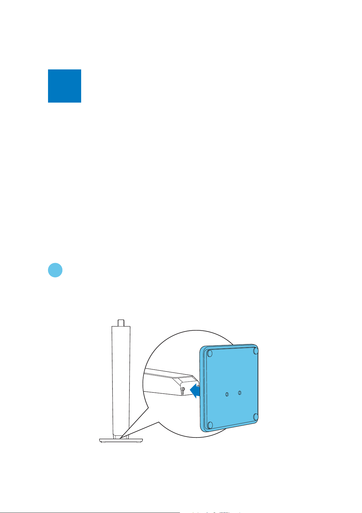
1
EN Stand mount the speakers
2-2
1
Page 11
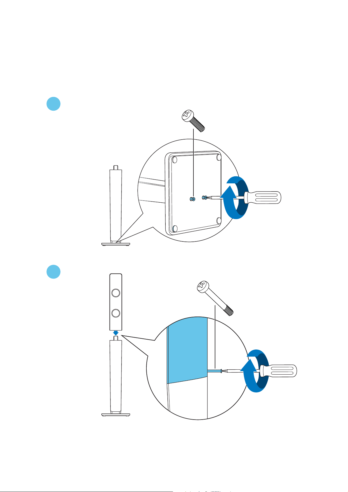
2
2-3
2x
3
1x
Page 12
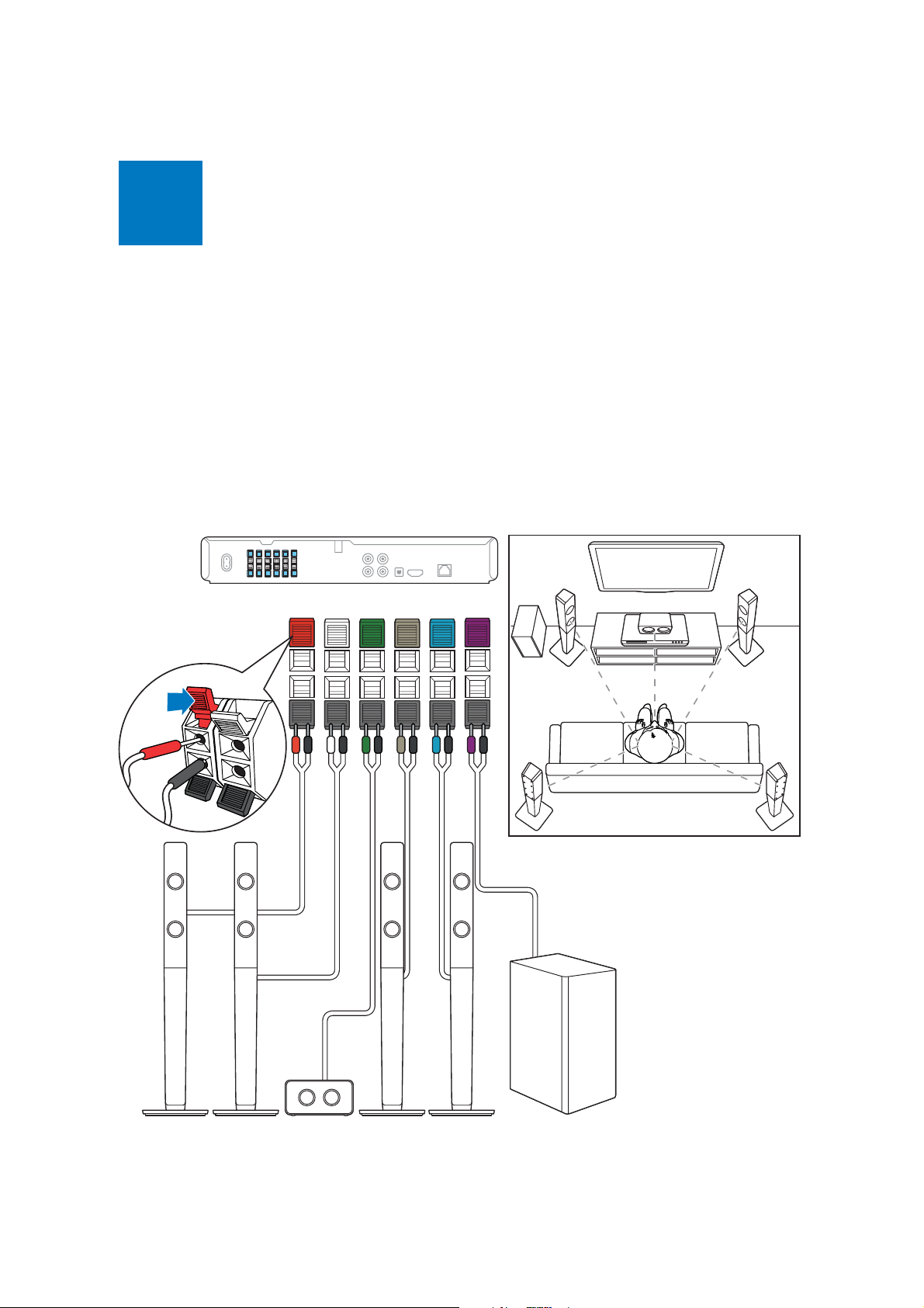
2
EN Connect the home theater
2-4
FRONT
RIGHT
FRONT
LEFT
FRONT
CENTER
REAR
RIGHT
REAR
LEFT
SUB-
WOOFER
SUB
WOOFER
REAR
LEFT
FRONT
LEFT
FRONT
CENTER
FRONT
RIGHT
REAR
RIGHT
FRONT
RIGHT
FRONT
LEFT
FRONT
CENTER
REAR
RIGHT
REAR
LEFT
SUB
WOOFER
Page 13

3
EN Connect to TV in one of these ways
2-5
HDMI ARC
HDMI OUT (ARC)
HDMI + OPTICAL
HDMI OUT (ARC)
OPTICAL
HDMI IN
HDMI IN (ARC)
OPTICAL
OPTICAL OUT
Page 14

HDMI + COAXIAL
2-6
COAXIAL
DIGITAL IN
COAXIAL
HDMI OUT (ARC)
HDMI + AUDIO L/R
LR
AUDIO IN
HDMI OUT (ARC)
COAXIAL
HDMI IN
LR
HDMI IN
AUDIO OUT
AUDIO L/R
Page 15

4
EN Switch on the home theater
1
2-7
2
3
Page 16
5
EN Complete the fi rst time setup
1
2-8
HDMI
2
3
4
5
6
HOME THEATERHOME THEATER
TV
3OHDVHVHOHFW\RXU
9LGHR
FRXQWU\DQGSUHVV2.
$XGLR
1HWZRUN
(DV\/LQN
3UHIHUHQFH
$GYDQFHG
0HQXODQJXDJH
$XGLR
6XEWLWOH
'LVF0HQX
3DUHQWDO&RQWURO
6FUHHQ6DYHU
$XWR6XEWLWOH6KLIW
&KDQJH3DVVZRUG
'LVSOD\3DQHO
$XWR6WDQGE\
9&'3%&
$XVWULD
%HOJLXP
$XWR(1*
(QJOLVK
ᇓ໗ࡩ
Page 17
6
EN Use your home theater
2-9
2
1
3
2
3
4
Page 18
MUSIC iLINK
2
1
1
3
2
3
3.5MM
STEREO
2-10
Page 19

2-11
1
LAN
LAN
Page 20

Your home theater
2-12
Congratulations on your purchase, and welcome
WR3KLOLSV7RIXOO\EHQHÀWIURPWKHVXSSRUWWKDW
Philips offers, register your product at
www.philips.com/welcome.
Main unit
This section includes an overview of the main unit.
Disc compartment
a
b
Display panel
c
(Open/Close)
Open or close the disc compartment, or
eject the disc.
d
(Play/Pause)
Start, pause or resume play.
Remote control
This section includes an overview of the remote control.
1
2
3
4
5
6
7
8
9
14
15
16
17
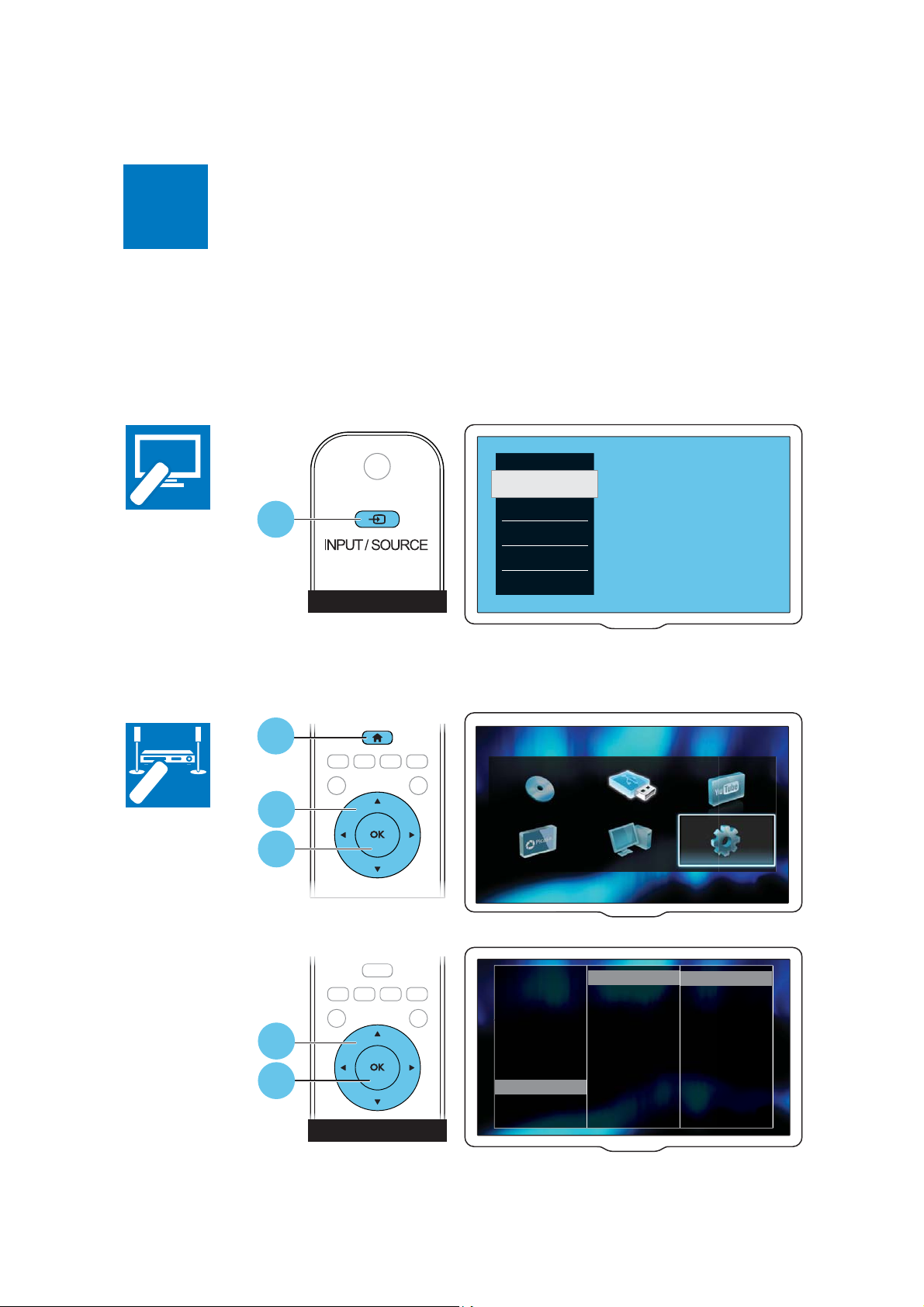
e
SOURCE
Select an audio or video source for the home
theater.
f
(Standby-On)
Switch the home theater on or to standby.
10
11
12
13
18
19
20
21
Page 21

(Standby-On)
a
Switch the home theater on or to standby.
When EasyLink is enabled, press and hold for
at least three seconds to switch all connected
HDMI CEC compliant devices to standby.
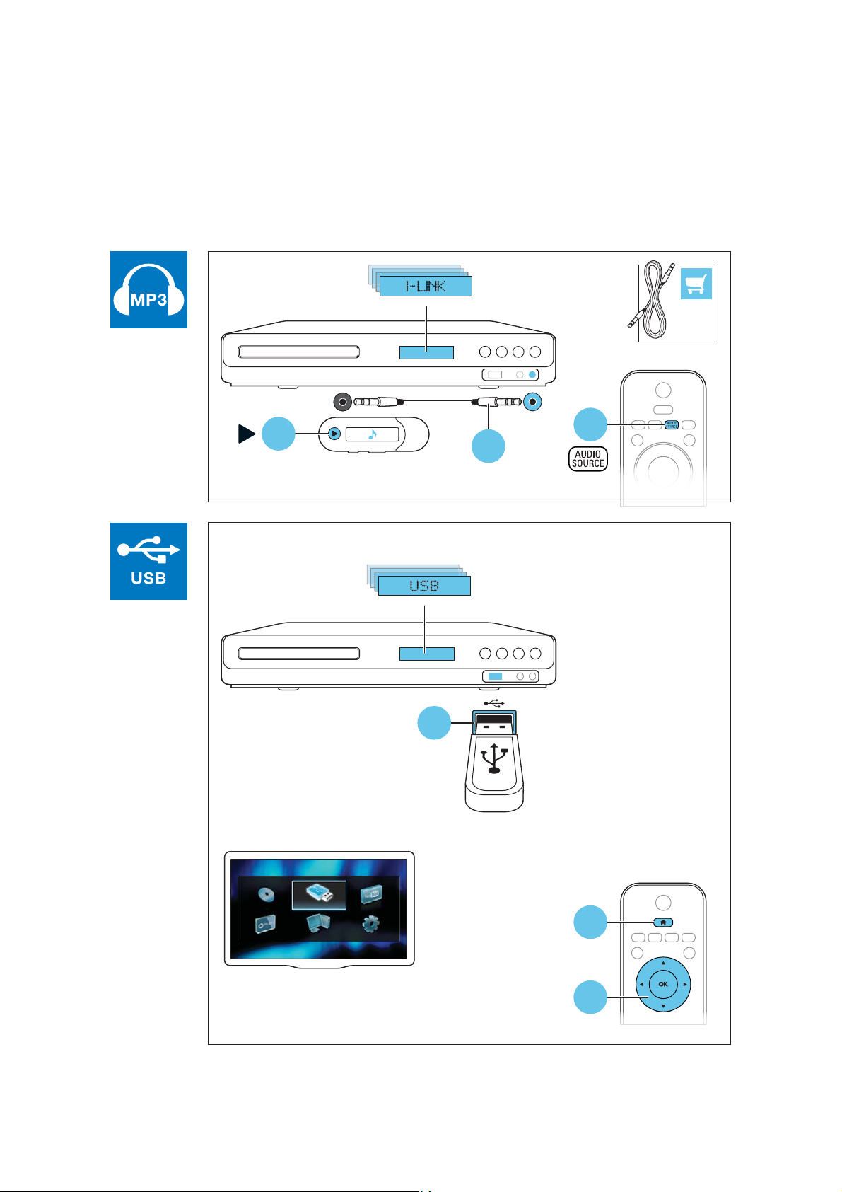
(Home)
b
Access the home menu.
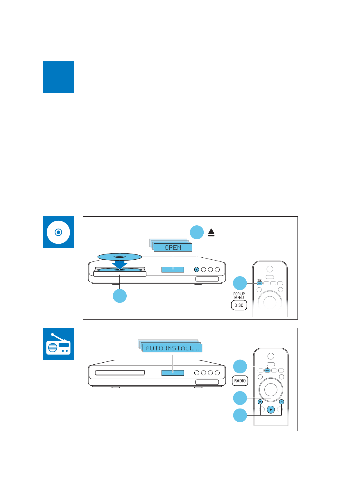
c Source buttons
DISC/POP-UP MENU : Switch to disc
source.Access or exit the disc menu
when you play a disc.
RADIO : Switch to FM radio.
AUDIO SOURCE : Select an audio input
source.
d
e
BACK
Return to a previous menu screen.
In radio mode, press and hold to erase
the current preset radio stations.
Navigation buttons
Navigate menus.
In radio mode, press left or right to start
auto search.
In radio mode, press up or down to tune
the radio frequency.
2-13
o
p
q
r
s
t
u
OPTIONS
Access more play options while playing a
disc or a USB storage device.
In radio mode, set a radio station.
(Play)
Start or resume play.
(Pause)
Pause play.
(Mute)
Mute or restore volume.
AUDIO
Select an audio language or channel.
SUBTITLE
Select subtitle language for video.
Color buttons
Select tasks or options for Blu-ray discs.
f
OK
&RQÀUPDQHQWU\RUVHOHFWLRQ
g
h
/ (Previous/Next)
Skip to the previous or next track,
FKDSWHURUÀOH
In radio mode, select a preset radio station.
(Stop) / (Eject/Open/Close)
Stop play.
Press and hold for three seconds to open or
close the disc compartment, or eject the disc.
i
/ (Fast Backward / Fast Forward)
Search backwards or forward. Press
repeatedly to change the search speed.
j +/- (Volume)
Increase or decrease volume.
k
SOUND SETTINGS
Access or exit sound options.
l
Alphanumeric buttons
Enter values or letters (using SMS style entry).
REPEAT
m
Select or turn off repeat mode.
n
TOP MENU
Access the main menu of a disc.
Page 22

3-1
Mechanical and Dismantling Instructions
Dismantling Instruction
The following guidelines show how to dismantle the player.
Step1: Remove 6 screws around the Top Cover, and then remove the Top Cover (Figure 1).
Detailed information please refer to the model set.
Step2: If it is necessary to dismantle Loader or Front Panel, the Front door should be removed first. (Figure 2)
Turn on the power button,then press open button to dismantle front door.Please kindly note that power off as soon
as front door is out of machine.
Note: Make sure to operate gently otherwise the guider would be damaged.
Figure 1
Please kindly note that dismantle the front door
assembly carefully to avoid damage tray and the front door.
Figure 2
Page 23

Mechanical and Dismantling Instructions
Dismantling Instruction
3-2
Detailed information please refer to the model set.
:Dismantle Front Panel, disconnect the connectors (XS604 XPS605 ,XP8), need release 2 snaps of Front Panel & 2 snaps
Step3
,
of bottom cabinet , then gently pull the Panel out from the set. (Figure 3)
Figure 3
Step4
: Dismantle Front Control Board,remove 5 screws (Figure 4
)
Figure 4
Step5
: Dismantle Loader, disconnect the 3 connectors (XP10, XP7,X P5
that connects the loader and the bottom cabinet. (Figure 5)
) aiming in the below figure, and remove 2 screws
Figure 5
Page 24

3-3
XP8
XS605
Mechanical and Dismantling Instructions
Dismantling Instruction
Detailed information please refer to the model set.
Step6
: Dismantle Main Board, first disconnect 3
: Dismantle Power Board, disconnect the connectors
Step7
Step8: Dismantle Amplifier Board, first disconnect connectors(XP702, ),and then remove
connector (XP13), and then remove7screws. (Figure
CN531,CN502,then remove
3 screws.(Figure 5/6)
5/6)
XP703
(Figure 5/6)
XP7
XP10
XP13
XS604
XP703
XP702
XP5
CN531
CN502
5 screws
Figure 6
Page 25

4-1
Software upgrade
Software upgrade method:
1.Copy the bin file as "HTS3592M2_XX.bin".
2.Then use the file to burn the upgrade CD-R/CD-RW.
3.Put the CD in the tray ,let the player loading the disc.
4.If the CD is correct ,it will display the Upgrade Menu ,press the PLAY key on the remote
control to start upgrade
5.Afer a while, the tray will open automatically ,but must not power off the player.
6.Don't power off ,wait until the player reset automatically ,the whole upgrade process may
need 2 minutes .HTS will auto standby after complete upgrade.
if you upgrade with USB device:
1.step1 is same with DISC upgrade;
2.Copy the renamed bin file(upgrade file) to the root menu of USB device.
3.connect the USB device to HTS ,and switch to USB source;
4.The rest is same to step 4,step 5 and step 6 with DISC upgrade.
Caution: The set must not be power off during
upgrading, Otherwise the Main board will be
damaged entirely.
Page 26

VFD No display on Front Control Board
VFD No display on
Front Control Board
Go
5-1 Trouble shooting Chart
Check every supply voltage on Main Board
whether normal or not.
(XP8 PIN4:-24V, PIN6: +5V, PIN5: 12V)
Yes
Check voltage -24V, +5V,+12V on Power
Board at CN502 position and Front Control
Board at XP2 PIN11:-24V PIN10:+12V
PIN9:+5V
Yes
Check the power key S608, open/closed key
K138, source key K135, paly/pause key
K136 on Front Board whether work normally
or not
Yes
Check Front Control Board signals at XP2
Pin8 VSCLK, Pin7 VSDA,Pin6 VSTB
No
Refer to XP501 on Power Board
No
Fix the connection XP2 on Front
Control Board and XP8 on Main Board
No
Replace MCU U4 on Main Board, or
replace the Main Board
No
Check the XP2 ON Front Control Board Pin6,
7, 8 arrive the condition IC U135 PIN7,9,10
Yes
Check whether bad solder exists on XP2 on
Front Control Board and U135 of VFD
Yes
Replace U135 or VFD
No
Correct connection
Page 27

keys do not work
keys do not work
Go
5-2 Trouble shooting Chart
Check voltage +5V on Front Board U135
PIN38
Yes
Check Front Control Board signals at XP2
Pin8 VSCLK, Pin7 VSDA,Pin6 VSTB
Yes
Replace U135 on Front Board
No
No
Fix the connection XP2 to XP8 on Main
Board
Replace U4 on Main Board, or
replace Main Board
Page 28

Remote control does not work
Remote control
does not work
Go
5-3 Trouble shooting Chart
Check battery of remote control whether
exhausted or not.
No
Check power supply of IR601 on Front
Control Board whether normal or not
XP2 Pin6 :+5V
Yes
Replace IR601
Yes
No
Replace the battery for remote
control
Check the +5V net on Front Control
Board to Main Board XP8
Page 29

No audio output
5-4 Trouble shooting Chart
No audio output
Go
Check voltage +26Vfor whether normal or
not at on Amplifier Board
Yes
Check the 24Pin FFC connection XP13 on
Main Board and XP702 on Amplifier Board
whether right or not between Main Board
and Amplifier Board
Yes
No
Check XP13 Pin 14&16 3.3V on Main
Board whether normal or not
Yes
Refer to XP501 on
Power Board
No
Check the control signal whether right or
not at the U8 Pin6, Pin7 on Main Board
and the signal at the XP13 Pin15 Pin16
Pin3
Yes
Replace Amplifier Board
No
Replace U8 on Main Board or
replace Main Board
Page 30

No video output
5-5 Trouble shooting Chart
No video output
Go
Check L452, R616 whether right on Main
Board
Yes
Check the video signal whether
right at U7: PIN B18 or R615
No
Replace Main IC or Main Board
No
Add L452, R616
Page 31

Can’t read disc or can’t open the disk door
ǃ
Can’t read disc or can’t
open the disk door
Go
5-6 Trouble shooting Chart
Check loader work normally or not
Yes
Check 45Pin, 8Pin, 4Pin cable from
Main Board to Loader connect right or
not
Yes
Replace Loader
No
Check XP7 on Main Board
No
Fix 45Pin, 8Pin, 4Pin cable
Page 32

Tuner FM does not work
Tuner FM does not work
Go
5-7 Trouble shooting Chart
Check voltage at Q28 C electrode
(+5V) on Main Board whether normal
or not
Yes
Check voltage +3.3V at Tuner
module (TUN1 Pin8) whether right or
not
Yes
Check Tuner module TUN1 Pin11,
Pin12 normal or not
Yes
Check the U8 PIN25, PIN26, I2C
output on Main Board normal or not
No
No
No
No
Refer to Power Board XP501
Check Main Board tuner power supply
circuit.
Change the Tuner module
Check Main Board U5 power
supply circuit
Yes
Replace main Board
Page 33

AUX in does not work
AUX in does not
work
Go
Check voltage at U27 PIN16:12V on Main
Board whether normal or not
Yes
5-8 Trouble shooting Chart
No
Refer to Power Board XP501
Check Main Board U27 Pin4, Pin11 signal
input whether right or not
Yes
Check U27 74HC4052 whether
broken
or not
Yes
Replace U27 74HC4052
No
No
Check AUX IN connector
Check Main Board U4
Page 34

MP3 Link does not work
MP3 Link does
not work
Go
Check signal at XS605 PIN3:MP3_R
PIN1:MP3_L ON front board whether normal or
not
Yes
5-9 Trouble shooting Chart
No
Refer to Main Board XP604
Check Main Board U18 74HC4052 PIN2,
PIN15 L/R signal input right or not
Yes
Check voltage at U18 74HC4052
PIN16,VDD +12V, on Main Board
Whether normal or not
Yes
Check U27 74HC4052 whether broken
or not
No
No
Check Main Board C358, C349, R340,
R457,
No
Refer to Power Board XP501
Check Main Board U4
Yes
Replace U27 74HC4052
Page 35

COAX in does not work
COAX in does
not work
Go
Check voltage at U27 PIN6/PIN23:3.3V on
Main Board whether normal or not
Yes
Check Main Board U27 CS8416 PIN2 input
signal whether normal or not
5-10 Trouble shooting Chart
No
Refer to Power Board XP501
No
Check Main Board C360,L11
Yes
Check U27 CS8416 whether broken.
or not
Yes
Replace U27 CS8416
No
Check Main Board U8
Page 36

Karaoke in does not work
Karaoke in does
not work
Go
Check signal at XS605 PIN5: MIC_in
signal from front board normal or not
Yes
Check Main Board U18 74HC4052 PIN5,
PIN14 L/R signal input right or not
5-11 Trouble shooting Chart
No
Refer to Main Board XP604
No
Check the cable between XP604 and XS605
Yes
Check U18 74HC4052 whether broken
not
Yes
Replace U18
or
No
Check Main Board U26
Page 37

Network in does not work
Network in does
not work
Go
Check
P1 Pin2, Pin3, Pin5, Pin6 from
netting twine
normal or not
Yes
5-12 Trouble shooting Chart
No
Check netting twine link normal or
not
Replace P1
Page 38

A
6-1
6-1
5
HTS35
92M2/93 Block /Wiring Diagram:
Notes:The differences between HTS3582 & HTS3582M2 are as below :
4
3
2
1
(red circle)
1.Main Board:HTS3582 use IC MT8555,HTS3582M2 use IC MT8560
2.Loader:HTS3582 use 05-L9829A-414V,HTS3582M2 use 05-L9829B-415
TUNER
AUX1
D D
USB
RJ45
(WIFI)
CVBS
HDMI
(1.4)
L/R
L/R L/R
4052*2
ARC(OPTI)
BD BOARD
MT8560
SDIN
I/O*3
PDN
L/R
AK5358
I2S
ASCLK
ALRCLK
I2S
I2S
I2C
C C
MOTOR
DRIVER
(In DEC modify to
TPIC1405A)
+TI2050G4
SPI
45P/0.5mm
B B
45P/0.5mm
8P/1.0mm
TPIC_A+
8P/1.0mm
TPIC_B+
TPIC_A-
TPIC_W
TPIC_COMMON
TPIC_B-
FLASH
NAND 2Gbit
4P/2.0mm
TPIC_V
TPIC_U
4P/2.0mm
TPIC_LOAD+
MGND
TPIC_LOAD-
TRAYIN#
DDR3x2
64Mx16x4pcs
DP
DN
4P/2.0mm
USB_DP
USB_DN
USB_5V
SDA
SCL
SI*2
14P/1.0mm
GND
VOL-
VOL+
USB__GND
INT
IR
I2C
CEC
MCU
WT61P8
IR
-24V
14P/1.0mm
12V
+5V -STB
VDAT
VFD-CLK
VSTB
IR
GND
VFD_CLK
VFD_DI/O
VFD_CS
GND
SCL
SDA
GND
MP3_L
I/O*3
PDN
GND
MIC
MP3_R
MIC_DET
MP3_INUSB
L/R
RESET
OPTI
CS8416
COAX
CS
I2C
RDS
POWER_DER
POWER_ON
STB5V
GND
ST12V
GND
STB5V
GND
POWER_ON
PVCC/8P
AMP_DET
AMP_MUTE
I2C
/PDN
BKND_ERR
-24V
I2S_SDATA0
I2S_LRCK
I2S_SDATA1
I2S_SDATA2
I2S_SCLK
GND
I2S_MCLK
GND
I2C_SCL
I2C_SDA
GND
AMP_MUTE
RESET
12V
12V
3.3V
3.3V
GND
GND
POWER_DER
NC
24P/0.5mm
AMP_DET
/PDN
BKND_ERR
AUDIO
PROCESSOR
TI5508
I2S
24P/0.5mm
6P/2.5MM8P/2.5mm
PDD
PDD
PDD
DGND
DGND
DGND
PVCC/8P
I2C
RESET
MUTE
BKND_ERR
PDN
POWER_DER
L/R PWM
SUB PWM
POWER DERATING
TI5342*3
MUTE
AMP_DET
SPK FR
SPK FL
SPK CEN
SPK RR
SPK RL
SPK SUB
AMP BOARD
AC IN
TR+
2.TILT+
TR-
1.TILT-
GND
MODEB
AUX1
FR+
CO_B-
IND
INA
INB
10.CO_A-
CO_B+
GND
CO_A+
FR-
PDIC
ING
INH
11.FO_IN
VCC_LD
RFO-
INC
HAVC
GND
BD_LD(8V)
FPDODVD
LDD_SDIO
30.GND
20.DRFO+
RFO+
21.DRFO-
GND
40.LDD_SEN
GND
31.GND
MODEA
GND
LDD_CLK
GND
41.GIO7
45.MODEC
INF
INE
L9829/TBL-2000+SANYO 414V
IR
IR
SPI
VFD_CLK
VFD_DI/O
VFD_CS
Front Board
VFD DRIVER
CS16312
POWER OPEN
SOURCE PALY
5V
12V
-24V
26V
LOADER
VFD DISPLAY
POWER BOARD
A
5
4
3
2
1
Page 39

7-1
7-1
A
B
C
D
E
Front Control Board Circuit Diagram for HTS3592M2/93:
VFD
+5V
R158
R158
10K
10K
POWER
POWER
S608
S608
VFD
AC1
R159
R159
10K
10K
A
R690
R690
47K
47K
R691
R691
47K
47K
VFD_32P_VFD200824
VFD_32P_VFD200824
F21F222G53G64G75G86G97G108G11NC12P1
NP31G
4
U135
U135
34
G4
35
G3
36
G2
37
G1
38
VDD
39
LED4
40
LED3
41
R148
R148
51K
51K
LED2
42
LED1
43
GND
44
OSC
MP3_R
R14
R14
100
100
A
R5
100R5100
P315P2
P416P517P618P719P8
13
14
20
-24V
LR24
26
31
33
27
G632G5
VEE
SEG1328SEG1429SEG1530SEG16
DRIVER_VFD_CS6312EN
DRIVER_VFD_CS6312EN
SW11SW22SW33SW44SDout5SDin6GND7SCLK8/CS9KEY110KEY2
R100R10
R171
R171
4.7K
4.7K
0
+5V
A
47pF/50V/NP0
47pF/50V/NP0
5
5
4
4
3
3
2
2
1
1
5PIN/2.0mm/100mm
5PIN/2.0mm/100mm
XS605
XS605
21
23
SEG1024SEG1125SEG12
SEG8
SEG7
SEG6/K6
SEG5/K5
SEG4/K4
SEG3/K3
SEG2/K2
SEG1/K1
KEY4
KEY3
11
R80R8
0
C145
C145
SEG9
VDD
R150 2.2KR150 2.2K
R149 2.2KR149 2.2K
C149
C149
47pF/50V/NP0
47pF/50V/NP0
R2 0R2 0
A
R692 0R692 0
C773
C773
A
100pF/50V/NP0
100pF/50V/NP0
P1427P1528NC29NP30F131F1
NC26P1325P1224P1123P1022P9
22
21
20
19
18
17
16
15
14
13
12
32
+5V
R161 2.2KR161 2.2K
C150
C150
47pF/50V/NP0
47pF/50V/NP0
A
AC2
R130R13
0
R1 0R1 0
K135K135
C223
C223
4.7uF/16V/Y5V
4.7uF/16V/Y5V
R174 47KR174 47K
K138K138
R152 47KR152 47K
K136K136
R151 47KR151 47K
R165 1KR165 1K
+5VA
STOP
OPEN
PLAY/PAUSE
R230R23
0
R6 0R6 0
R4 0R4 0
R9 0R9 0
C774
C774
NC/0.1uF/16V/Y5V
NC/0.1uF/16V/Y5V
3.3uF/50VCE138+3.3uF/50VCE138
R154 1KR154 1K
JACK602
JACK602
MIC JACK
MIC JACK
R136
R136
2.2
2.2
R139 470R139 470
-24V
AC2
BZX79C6V2
BZX79C6V2
R70R7
0
KEY_POW
ZD135
ZD135
R120R12
0
1
6
3
5
4
2
LR24
ZD136
ZD136
BZX79C5V1
BZX79C5V1
VSDA
VSCLK
VSTB
1
6
3
5
4
2
R140 330R140 330
R144
R144
10K
10K
C222
C222
4.7uF/16V/Y5V
4.7uF/16V/Y5V
R162 100R162 100
R163 100R163 100
R164 100R164 100
+3.3V
R653
R653
10K
10K
R250R25
0
FB615
FB615
FB616
FB616
A
C148
C148
0.1uF/50V/X7R
0.1uF/50V/X7R
600/200mA
600/200mA
600/200mA
600/200mA
+
+
CE135
CE135
3.3uF/50V
3.3uF/50V
+5VA
R635
R635
100
100
R141 5.6R141 5.6
R157
R157
10K
10K
+12V
R30R3
R135
R135
0
470
Q138
Q138
NPN_3DG3904M
NPN_3DG3904M
R146
R146
10K
10K
REM-3V3
1
U602A
U602A
AS4558M
AS4558M
470
R138
R138
470
470
+12VA
Q135
Q135
NPN_3DG3904M
NPN_3DG3904M
Q137
Q137
PNP_3CG3906M
PNP_3CG3906M
+12V
R260R26
0
+
14PIN/1.0mm
14PIN/1.0mm
XP2
XP2
14
14
13
13
12
IR601
IR601
GND
VCC
GND
GND
IRM_12mm
IRM_12mm
6
Shell B
GND
Shell A
5
IR
VCC
D-
D+
P801
P801
USB-A/BK
USB-A/BK
12
11
11
10
10
9
9
8
8
7
7
6
6
5
5
4
4
3
3
2
2
1
1
C766100pF/50V/NP0 C766100pF/50V/NP0
C767
C767
C771
C771
C765
C765
100pF/50V/NP0
100pF/50V/NP0
100pF/50V/NP0
100pF/50V/NP0
1
2
3
4
5
1
2
3
4
IR
C617
C618
C618
47pF/50V/NP0
47pF/50V/NP0
USB_VCC USB_VCC
USB_DM
USB_DP
C617
0.1uF/16V/Y5V
0.1uF/16V/Y5V
01UUSBJAK-101
1 1
To main board
2 2
3 3
JACK601
JACK601
MIC JACK
MIC JACK
4 4
1
1
6
6
3
3
5
5
4
4
2
2
CE1
CE1
10uF/16V
10uF/16V
FB611 600/200mAFB611 600/200mA
A
R151KR15
1K
+
+
R181MR18
1M
100pF/50V/NP0
100pF/50V/NP0
C769
C769
C764
C764
100pF/50V/NP0
100pF/50V/NP0
R638
R638
100
100
+
+
CE606
CE606
47uF/16V
47uF/16V
+12V
+3.3V
R16
R16
2.2K
2.2K
Q1
Q1
NPN_3DG3904M
NPN_3DG3904M
R17
R17
470
470
R240R24
0
100pF/50V/NP0
100pF/50V/NP0
R637
R637
10K
10K
C1
C1
1uF/16V/Y5V
1uF/16V/Y5V
C763
C763
100pF/50V/NP0
100pF/50V/NP0
REM-3V3
R609 2.2KR609 2.2K
FB613 500/800mAFB613 500/800mA
FB604 500/800mAFB604 500/800mA
FB609 500/600mAFB609 500/600mA
FB610 500/800mAFB610 500/800mA
FB612 500/800mAFB612 500/800mA
FB614 500/800mAFB614 500/800mA
KEY_POW
C768
C768
100pF/50V/NP0
100pF/50V/NP0
USB_DM USB_DP
USB_VCC
4
4
3
3
2
USB_DM
2
1
USB_DP
1
4PIN/2.0mm/200mm
4PIN/2.0mm/200mm
XS604
To main board
CE610
CE610
+
+
2.2uF/25V
2.2uF/25V
R612
R612
10K
10K
A
R19
R19
10K
10K
Q2
Q2
PNP_3CG3906M
PNP_3CG3906M
D1 1N4148D1 1N4148
R20
R20
150K
150K
MIC_DET
GND
-24V
+12V
+3.3V
VSCLK
VSDA
VSTB
GND
IR
12VA
+
+
CE608
CE608
220uF/16V
220uF/16V
R648
R648
5.6K
5.6K
C2
C2
1uF/16V/Y5V
1uF/16V/Y5V
ESD1
ESD1
4
PRTR5V0U2X
PRTR5V0U2X
R21
R21
10K
10K
+3.3V
23
1
C772
C772
0.1uF/25V/Y5V
0.1uF/25V/Y5V
1000pF/50V/X7R
1000pF/50V/X7R
A
R646
R646
22K
22K
C607
C607
REFM
R22
R22
10K
10K
MIC_DET
Q3
Q3
NPN_3DG3904M
NPN_3DG3904M
+5VA
R142 18KR142 18K
Q139
Q139
NPN_3DG3904M
NPN_3DG3904M
C135
C135
1000pF/50V/X7R
1000pF/50V/X7R
+12V
C611 47pF/50V/NP0C611 47pF/50V/NP0
R643
R643
47K
47K
A
AS4558M
AS4558M
U602B
U602B
-
-
6
7
+
+
5
8 4
12VA
R137
R137
10K
10K
NPN_3DG3904M
NPN_3DG3904M
10K
10K
R683
R683
C623
C623
2.2uF/16V/Y5V
2.2uF/16V/Y5V
100pF/50V/NP0
100pF/50V/NP0
Q136
Q136
C152 0.1uF/50V/X7RC152 0.1uF/50V/X7R
R143 4.7KR143 4.7K
R1451KR145
1K
R1471KR147
1K
+3.3V
R61110R611
10
LED1
LED1
LED_RED
LED_RED
R684
R684
750
750
Q620
Q620
PNP_3CG3906M
PNP_3CG3906M
R686
R686
7.5K
7.5K
REFM
CE609
CE609
+
47uF/16V
47uF/16V
R642
R642
100K
100K
R11
R11
C610
C610
+
A
NC/0
NC/0
3
2
R649
R649
20K
20K
C626 47pF/50V/NP0C626 47pF/50V/NP0
C625
C625
2.2uF/16V/Y5V
2.2uF/16V/Y5V
A
84
+
+
-
-
R645100KR645100K
R610
R610
22K
22K
AA
A
B
C
D
E
Page 40

7-2
7-2
A
Power Board Circuit Diagram for HTS3592M2/93:
HV
BD501
BD501
1
GBU4M
GBU4M
1 1
R503
R503
220/1W
220/1W
2 2
RV504
RV504
200V/500A
200V/500A
3
R502CNCR502C
NC
0.22uF/250VAC
0.22uF/250VAC
CY501
CY501
100pF/250VAC
100pF/250VAC
0.22uF/250VAC
0.22uF/250VAC
R502ANCR502A
NC
R501 1MR501 1M
3 3
TR501
TR501
NTC/3ohm/5A
NTC/3ohm/5A
CY505NCCY505
NC
CN501
CN501
2PIN/7.92mm
2PIN/7.92mm
LIF502
LIF502
8.5mH
8.5mH
CX502
CX502
LIF501
LIF501
6.6mH
6.6mH
CX501
CX501
RV501
RV501
VDR/560V
VDR/560V
-+
-+
4
R502DNCR502D
NC
CY502
CY502
100pF/250VAC
100pF/250VAC
R502BNCR502B
NC
2
112
2
F501
F501
FUSE_6.3A/250V
FUSE_6.3A/250V
4 4
CE501
CE501
+
+
220uF/450V
220uF/450V
+
+
100uF/400V
100uF/400V
Alternative
HV
CE5011
CE5011
+
+
100uF/400V
100uF/400V
1
HV
2
3
T531D
5
T531G
6
T531F
CE502
CE502
VDD
N.C
D
P-GND
FB
T5311
T5311
ER28
ER28
R5091MR509
1M
A11
A12
C539
C539
4700pF/400VAC
4700pF/400VAC
8
A8
9
A9
T501D
11
T531N
12
T501F
T501G
T531P
T531P
HV
R5041MR504
1M
+
+
5
1
3
2
1
HV
CE5021
CE5021
220uF/450V
220uF/450V
T5011
T5011
EEL19
EEL19
C5312
C5312
4700pF/400VAC
4700pF/400VAC
9
T501P12
7
8
10
6
8
C502
C502
0.47uF/63V
0.47uF/63V
T501P5
T501N
T501P24
T501P5
T501N
D507
D507
1N4148
1N4148
B
R522
R522
2.2M
2.2M
R5362MR536
R531NCR531
NC
2M
R532NCR532
R5372MR537
NC
2M
R533NCR533
NC
HV
U501
U501
TNY179PN
TNY179PN
5
S
6
S
7
S
S8EN/UV
Q501
Q501
PNP_MMBT8550CLT1
PNP_MMBT8550CLT1
Q502
Q502
PNP_MMBT8550CLT1
PNP_MMBT8550CLT1
R534
R534
47K/2W
47K/2W
C541
C541
100pF/1KV
100pF/1KV
Drain
NC
BP/M
R505
R505
150K
150K
4
3
2
1
C531
C531
4700pF/400VAC
4700pF/400VAC
R53522R535
22
D531
D531
FR207/2A/1000V
FR207/2A/1000V
D
D
CONTROL
CONTROL
S
S
R526
R526
150K
150K
R523
R523
100
100
R524
R524
100K
100K
U531
U531
V
V
X
X
F
F
R527
R527
150K
150K
FR107/1A/1000V
FR107/1A/1000V
R507
R507
150
150
R508
R508
22K
22K
+
+
CE505
CE505
10uF/16V
10uF/16V
R55622R556
22
top261EN
top261EN
C
C
0.1uF/50V/X7R
0.1uF/50V/X7R
C532
C532
R528
R528
150K
150K
D505
D505
R538
R538
6.8
6.8
47uF/35V
47uF/35V
+
+
CE531
CE531
C5311
C5311
4700pF/400VAC
4700pF/400VAC
Alternative
R55722R557
22
D534
D534
HER308/3A/1000V
HER308/3A/1000V
Alternative
R5480R548
0
C501
C501
2200pF/1KV
2200pF/1KV
R50622R506
22
ZD502
ZD502
BZX79C18
BZX79C18
D506
D506
FR107/1A/1000V
FR107/1A/1000V
ZD503
ZD503
BZX79C11
BZX79C11
T531D
T531G
D532 FR104/1A/400VD532 FR104/1A/400V
R5400R540
0
R539
R539
100
100
+
+
CE532
CE532
47uF/50V
47uF/50V
T501D
D512
D512
+10V
FR107/1A/1000V
FR107/1A/1000V
+
+
CE504
CE504
47uF/35V
47uF/35V
1
2
3
5
6
T531F
ZD531
ZD531
BZX79C8V2
BZX79C8V2
Alternative
T501F
T501G
HV
C
CY506
CY506
1000pF/250VAC
1000pF/250VAC
T531
T531
PQ3230
PQ3230
Alternative
VDD
N.C
D
P-GND
FB
43
CY503
CY503
220pF/250VAC
220pF/250VAC
CY504NCCY504
NC
T501
T501
EF25
EF25
5
1
3
2
4
43
CY507
CY507
100pF/250VAC
100pF/250VAC
C533 1500pF/1KVC533 1500pF/1KV
1
8
T531P
A8
9
A9
3
D533 MUR2020FCT/20A/200VD533 MUR2020FCT/20A/200V
10
A10
12
A12
T531N
12
U532
U532
BPC-817B
BPC-817B
U533
U533
3
AZ431LBZ
AZ431LBZ
2
D562 BAS316/100V/0.5AD562 BAS316/100V/0.5A
D561 MBRX120/20V/1AD561 MBRX120/20V/1A
Alternative Alternative
C503
C503
1000pF/1KV
1000pF/1KV
P
T501P12
9
7
8
T501N
10
T501P24
6
T501P5
D514
D514
MBRF1045/10A/45V
MBRF1045/10A/45V
Alternative
8
R511 470R511 470
12
U502
U502
BPC-817B
BPC-817B
P
JP506
JP506
Jumper
Jumper
Alternative
2
+
+
R541
R541
470
470
ZD532
ZD532
BZX79C12
BZX79C12
R542
R542
2.2K
2.2K
C535 0.1uF/50V/X7RC535 0.1uF/50V/X7R
R543
R543
10K
10K
1
D511
D511
HER203G/2A/200V
HER203G/2A/200V
D515
D515
SR360/3A/60V
SR360/3A/60V
Alternative
SR360/3A/60V
SR360/3A/60V
CE533
CE533
820uF/50V
820uF/50V
P
D510
D510
Jumper
R549
R549
220/3W
220/3W
Jumper
Jumper
Jumper
Alternative
+
+
CE534
CE534
820uF/50V
820uF/50V
R571
R571
10 mR
10 mR
R5721KR572
1K
C534
C534
0.1uF/50V/X7R
0.1uF/50V/X7R
R51422R514
22
+
+
CE506
CE506
1000uF/16V
1000uF/16V
Alternative Alternative
D508
D508
FR107/1A/1000V
FR107/1A/1000V
C504
C504
2200pF/50V/X7R
2200pF/50V/X7R
D513
D513
SR360/3A/60V
SR360/3A/60V
R512
R512
2.2K
2.2K
U503
U503
3
AZ431LBZ
AZ431LBZ
1
2
R51322R513
22
+
+
CE509
CE509
1500uF/16V
1500uF/16V
C505
C505
0.1uF/50V/X7R
0.1uF/50V/X7R
CE535
CE535
820uF/50V
820uF/50V
R546NCR546
NC
+
+
CE507
CE507
470uF/16V
470uF/16V
+
+
1000uF/16V
1000uF/16V
Alternative
CE511
CE511
R601 0R601 0
P
0.1uF/50V/X7R
0.1uF/50V/X7R
+
+
R515
R515
22K
22K
R520NCR520
NC
JP505
JP505
JP504
JP504
L5312.9uH L5312.9uH
R544
R544
75K/1%
75K/1%
R573
R573
2.2K
2.2K
OP
R545
R545
4.7K/1%
4.7K/1%
Remote on/off
Standby mode: Q561, D561 OFF; D562 ON
On mode: Q561, D561 ON; D562 OFF
L503
L503
3.3uH/3A
3.3uH/3A
+
+
CE508
CE508
47uF/50V
47uF/50V
R52522R525
22
L502
L502
3.3uH/3A
3.3uH/3A
+
+
CE510
CE510
1500uF/16V
1500uF/16V
R516 10KR516 10K
D
C538
C538
D536
D536
1N4148
1N4148
D535
D535
1N4148
1N4148
R521
R521
10K
10K
R518
R518
2.49K/1%
2.49K/1%
R519
R519
2.4K/1%
2.4K/1%
R550
R550
33K
33K
+
+
CE537
CE537
22uF/50V
22uF/50V
NPN_MMBT8050CLT1
NPN_MMBT8050CLT1
C564
C564
0.1uF/50V/X7R
0.1uF/50V/X7R
R517NCR517
NC
+43V
Q561
Q561
C563
C563
0.1uF/50V/X7R
0.1uF/50V/X7R
+12V
M+5V
PCON
6PIN/2.5mm/70mm
6PIN/2.5mm/70mm
R561
R561
1.5K
1.5K
0.1uF/50V/X7R
0.1uF/50V/X7R
CN531
CN531
1
1
2
2
3
3
4
4
5
5
6
6
C571
C571
0.1uF/50V/X7R
0.1uF/50V/X7R
R567
R567
1.5K
1.5K
C561
C561
8PIN/2.5mm/120mm
8PIN/2.5mm/120mm
1
2
3
4
5
6
7
8
1:+43V
2:+43V
3:+43V
4:GND
5:GND
6:GND
U561
U561
BPC-817B
BPC-817B
R562
R562
2.2K
2.2K
R5631KR563
1K
CE538
CE538
22uF/16V
22uF/16V
CN502
CN502
1
2
3
4
5
6
7
8
+10V
43
+
+
1:-24V
2:GND
3:+12V
4:GND
5:M+5V
6:M+5V
7:P_on/off
8:GND
8
V+
V+
3
+
+
2
-
-
V-
V-
4
P
M+5V
R5651KR565
1K
12
OPP
Q562
Q562
NPN_MMBT8050CLT1
NPN_MMBT8050CLT1
R555
R555
1.5K/1%
1.5K/1%
R554
R554
2.21k/1%
2.21k/1%
U573A
U573A
LM3580
LM3580
<Package>
<Package>
1
R5741KR574
1K
C562
C562
0.1uF/50V/X7R
0.1uF/50V/X7R
TR532
TR532
NTC/10Kohm
NTC/10Kohm
C540
C540
0.1uF/50V/X7R
0.1uF/50V/X7R
BD mode
T501:EF25
U501:TNY179P
+12V:
D511:HER203
C503:1000pF/1kV
R514:22/1206
CE506:1000uF/16V
CE507:470uF/16V
+5V:
D510:SR360
CE509:2200uF/16V
CE510:1000uF/16V
CE511:1000uF/16V
C572
C572
0.1uF/50V/X7R
0.1uF/50V/X7R
P
LOOP
R552
R552
2.21k/1%
2.21k/1%
NPN_3DG3904M
NPN_3DG3904M
E
Q571
Q571
R57510R575
PNP_MMBT8550CLT1
PNP_MMBT8550CLT1
10
D572
D572
1N4148
1N4148
C573
C573
0.1uF/50V/X7R
0.1uF/50V/X7R
PCON
R566
R566
2.2K
2.2K
Q563
Q563
R5641KR564
1K
100K
100K
R600
R600
R553
R553
2.21k/1%
2.21k/1%
PP P P
Alternative
R578
R578
10K
10K
R5761KR576
1K
OPP
OPP Circuit
R570
R570
100
100
PNP_3CG3906M
PNP_3CG3906M
Q564
Q564
C565
C565
0.01uF/50V/X7R
0.01uF/50V/X7R
OVP Circuit
U573B
U573B
LM3580
LM3580
8
<Package>
<Package>
V+
V+
5
+
+
6
-
-
V-
V-
4
DVD mode
T501:EEL19
U501:TNY177P
+12V:
D511:FR107
C503:NC
R514:NC
CE506:470uF/25V
CE507:220uF/25V
+5V:
D510:NC
CE509:1000uF/16V
CE510:NC
CE511:470uF/16V
R577
R577
2.2K
2.2K
+43V
ZD561
ZD561
BZX79C39
BZX79C39
R5691KR569
1K
R5681KR568
1K
7
OTP Circuit
M+5VLOOP
D573
D573
1N4148
1N4148
OP
* CAUTION :
THE PARTS MARKED WITH ARE IMPORTANT PARTS ON THE SAFETY.
PLEASE USE THE PARTS HAVING THE DESIGNATED PARTS NUMBER WITHOUT FAIL.
A
B
C
D
E
Page 41

7-3
7-3
A
B
C
D
E
Amplifier Board Circuit Diagram for HTS3592M2//93:DSP
ADD FB8 AND +12V-FAN
NET FOR FAN
24PIN/0.5mm
24PIN/0.5mm
25
26
D
1 1
1
2
3
4
SHUT_DOWN
5
6
7
8
9
10
11
12
RESET
TOP
TOP
13
DSP_MUTE
14
GND
15
I2C_SDA
16
I2C_SCL
17
GND
18
MCLK
19
GND
20
BICK
21
22
23
LRCLK
24
XP703
XP703
27
28
D D
2 2
M_MUTE
3 3
1/2power-control
OTW
GND
CHANGE Q701 FROM
8050 TO 3904
+12V
D770
D770
LL4148
LL4148
D776
D776
LL4148
LL4148
FB8
FB8
+12V-FAN
70/1A
70/1A
TP63TP63
TP60TP60
OTW
TP57TP57
1/2power-control
TP48TP48
TP47TP47
TP46TP46
500/800mA
500/800mA
TP45TP45
TP25TP25
R11
R11
47K
47K
CE713
CE713
+
+
PNP_3CG3906M
PNP_3CG3906M
220uF/16V
220uF/16V
D
R847
R847
2.7K
2.7K
D D
+12V
+3.3V
FB712500/800mA FB712500/800mA
FB711
FB711
TP43TP43
TP42TP42
TP39TP39
TP33TP33
TP32TP32
TP24TP24
TP23TP23
TP22TP22
TP21TP21
TP20TP20
+12V
+
C713
C713
0.1uF/50V/X7R
0.1uF/50V/X7R
R10
R10
Q701
Q701
47K
47K
+12V-FAN
CE24
CE24
+
+
47uF/16V
47uF/16V
D
CHANGE Q7 FROM
8050 TO 3904
+12V
CE746
CE746
+
+
4.7uF/50V
4.7uF/50V
+
CE724
CE724
47uF/16V
47uF/16V
D D
CHANGE R9 /R10 FROM
0402 TO 0603
Power ON / OFF Mute
NC/0.1uF/50V/X7R
NC/0.1uF/50V/X7R
R1301KR130
1K
D
0.1uF/50V/X7R
0.1uF/50V/X7R
R8
C90
C90
47KR847K
D
+12V-A
R83010R830
10
0.1uF/50V/X7R
0.1uF/50V/X7R
D
R839 5.6KR839 5.6K
CHANGE U705 FROM A4558 TO LM358
4 4
+3.3V
4.7K
R762 0R762 0
R761 0R761 0
R760 0R760 0
C716
C716
D D
Q3
Q3
PNP_S8550C
PNP_S8550C
R76
R76
4.7K
4.7K
NPN_3DG3904M
NPN_3DG3904M
D
C792
C792
Q7
Q7
1
+12V-A
4.7K
4.7K
4.7K
4.7K
R851
R851
0.1uF/50V/X7R
0.1uF/50V/X7R
R9
47KR947K
-
+
+
8 4
4.7K
R809
R809
R850
R850
R758 47R758 47
R746 47R746 47
R745 47R745 47
R734 47R734 47
R732 47R732 47
R731 47R731 47
R730 47R730 47
R729 47R729 47
+3.3V
C715
C715
Q702
Q702
NPN_3DG3904M
NPN_3DG3904M
CE39
CE39
220uF/16V
220uF/16V
+
+
2
3
U705A
U705A
LM358
LM358
R844
R844
5.6K
5.6K
4.7K
4.7K
R852
R852
+
+
CE726
CE726
47uF/16V
47uF/16V
R80150 R80150
R79150 R79150
R133
R133
5.6K
5.6K
0.1uF/50V/X7R
0.1uF/50V/X7R
C823
C823
0.1uF/50V/X7R
0.1uF/50V/X7R
R791 2KR791 2K
4.7K
4.7K
R855
R855
R853
R853
R854
R854
4.7K
4.7K
4.7K
4.7K
C103910pF/50V/NP0 C103910pF/50V/NP0
C103810pF/50V/NP0 C103810pF/50V/NP0
add R718 R717
R7170R717
0
C101
C101
0.1uF/50V/X7R
0.1uF/50V/X7R
D
+12V-A
7
8 4
C825
C825
CHANGE R723/R722
FROM 0402 TO 0603
R718
R718
NC /0
NC /0
-
+
+
U705B
U705B
LM358
LM358
4.7K
4.7K
R856
R856
C104010pF/50V/NP0 C104010pF/50V/NP0
6
5
C10150.01uF/50V/X7R C10150.01uF/50V/X7R
C10220.01uF/50V/X7R C10220.01uF/50V/X7R
C104110pF/50V/NP0 C104110pF/50V/NP0
C103710pF/50V/NP0 C103710pF/50V/NP0
C104210pF/50V/NP0 C104210pF/50V/NP0
D
VALID
add C744 ,for EMC
1
1
2
2
XP8
XP8
2PIN/2.0mm
2PIN/2.0mm
R134
R134
5.6K
5.6K
R139
R139
5.6K
5.6K
R722 15KR722 15K
R723
R723
30K
30K
R137
R137
C10230.01uF/50V/X7R C10230.01uF/50V/X7R
C104310pF/50V/NP0 C104310pF/50V/NP0
1.2K
1.2K
R724
R724
150K
150K
adjust FAN START,change R791/R137/R139 value 2011.8.22
C10240.01uF/50V/X7R C10240.01uF/50V/X7R
C104410pF/50V/NP0 C104410pF/50V/NP0
D
R820
R820
68K
68K
D
M_CLK
/BKND_ERR
/PDN
/RESET_MODULATOR
M_MUTE
SDA-A
SCL-A
S_CLK
SDIN3
SDIN2
L_RCLK
SDIN1
+3.3V
1000pF/50V/X7R
1000pF/50V/X7R
D
+
+
CE744
CE744
100uF/16V
100uF/16V
R135
R135
10uF/10V/Y5V
10uF/10V/Y5V
CE720
CE720
4.7
4.7
R784
R784
4.7K
4.7K
C744
C744
D720 LL4148D720 LL4148
D719 LL4148D719 LL4148
D718 LL4148D718 LL4148
D717 LL4148D717 LL4148
D714 LL4148D714 LL4148
D715 LL4148D715 LL4148
C718
C718
0.01uF/50V/X7R
0.01uF/50V/X7R
0.1uF/50V/X7R
0.1uF/50V/X7R
C738
C738
0.1uF/50V/X7R
0.1uF/50V/X7R
1000pF/50V/X7R
1000pF/50V/X7R
R788
R788
4.7K
4.7K
D
R8268.2K R8268.2K
R8258.2K R8258.2K
R747
R747
200
200
C736
C736
R8278.2K R8278.2K
R7758.2K R7758.2K
D
D
0.1uF/50V/X7R
0.1uF/50V/X7R
C735
C735
R795
R795
100K
100K
R8298.2K R8298.2K
R8288.2K R8288.2K
R136 4.7R136 4.7
0.01uF/50V/X7R
0.01uF/50V/X7R
R733
R733
200
200
C734
C734
/RESET_MODULATOR
C740
C740
1uF/16V/Y5V
1uF/16V/Y5V
CE723
CE723
10uF/10V/Y5V
10uF/10V/Y5V
0.1uF/50V/X7R
0.1uF/50V/X7R
CE706
CE706
+
+
4.7uF/50V
4.7uF/50V
CE705
CE705
+
+
4.7uF/50V
4.7uF/50V
CE704
CE704
+
+
4.7uF/50V
4.7uF/50V
CE701
CE701
+
+
22uF/50V
22uF/50V
CE702
CE702
+
+
4.7uF/50V
4.7uF/50V
CE703
CE703
+
+
4.7uF/50V
4.7uF/50V
0.1uF/50V/X7R
0.1uF/50V/X7R
C732
C732
C709
C709
C733
C733
0.1uF/50V/X7R
0.1uF/50V/X7R
/PDN
+3.3V
R7491R749
1
C739
C739
0.1uF/50V/X7R
0.1uF/50V/X7R
DD
C727
C727
R752 1KR752 1K
R751 1KR751 1K
R741 1KR741 1K
R719 1KR719 1K
R720 1KR720 1K
R721 1KR721 1K
CHANGE FROM
1% TO 5%
M_CLK
1
VRA_PLL
2
PLL_FLT_RET
3
PLL_FLTM
4
PLL_FLTP
5
AVSS
6
AVSS
7
VRD_PLL
8
AVSS_PLL
9
AVDD_PLL
10
VBGAP
11
RESET
12
HP_SEL
13
PDN
14
MUTE
15
DVDD
16
DVSS
0.1uF/50V/X7R
0.1uF/50V/X7R
C741
C741
0.1uF/50V/X7R
0.1uF/50V/X7R
CEN-
SL-
SR-
SW-
R-
L-
CE719
CE719
10uF/10V/Y5V
10uF/10V/Y5V
D
62
59
61
63
64
RESERVED
VR_DPLL17OSC_CAP18XTL_OUT19XTL_IN20RESERVED21RESERVED22RESERVED23SDA24SCL25LRCLK26SCLK27SDIN428SDIN329SDIN230SDIN131PSVC
C726
C726
C737
C737
15pF/50V/NP0
15pF/50V/NP0
MCLK
PWM_HPP_R
R46
R46
680
680
Y2
Y2
13.5MHz/30PPM
13.5MHz/30PPM
R7541MR754
1M
60
PWM_HPP_L
PWM_HPM_R
D
C725
C725
15pF/50V/NP0
15pF/50V/NP0
PWM_HPM_L
58
PWM_P_6
TAS5508
TAS5508
57
PWM_M_6
U714
U714
C728
C728
0.1uF/50V/X7R
0.1uF/50V/X7R
56
55
PWM_P_5
PWM_M_5
+3.3V
R748
R748
4.7
4.7
54
DVDD_PWM
6PIN/2.5mm
6PIN/2.5mm
XP702
XP702
53
52
DVSS_PWM
1
2
3
4
5
6
51
PWM_P_8
PWM_M_8
1
2
3
4
5
6
50
49
PWM_P_7
32
TP36TP36
0.1uF/50V/X7R
0.1uF/50V/X7R
D
PWM_M_7
VR_PWM
PWM_P_4
PWM_M_4
PWM_P_3
PWM_M_3
PWM_P_2
PWM_M_2
PWM_P_1
PWM_M_1
BKND_ERR
C826
C826
TP64TP64
VALID
DVSS
DVDD 1
DVSS
DVSS
VR_DIG
0.1uF/50V/X7R
0.1uF/50V/X7R
C802
C802
R768
R768
3.3
3.3
LAYOUT NOTE:
EMI SNUBBER
PLACE TO THE
RIGHT OF U100
48
47
46
45
44
43
42
41
40
39
38
37
36
35
34
33
C729
C729
0.1uF/16V/X7R
0.1uF/16V/X7R
0.1uF/50V/X7R
0.1uF/50V/X7R
C828
C828
LAYOUT NOTE:
EMI SNUBBER
PLACE TO THE
LEFT OF U100
C731
C731
0.1uF/16V/X7R
0.1uF/16V/X7R
D
D
DVDD1
DVDD1
CE725
CE725
10uF/10V/Y5V
10uF/10V/Y5V
0.1uF/50V/X7R
0.1uF/50V/X7R
C829
C829
R703
R703
100
100
R704
R704
100
100
R705
R705
100
100
R706
R706
100
100
R707
R707
100
100
R708
R708
100
100
R709
R709
100
100
R710
R710
100
100
R711
R711
100
100
R712
R712
100
100
R713
R713
100
100
R714
R714
100
100
R7151KR715
1K
R750
R750
100
100
C742
C742
0.1uF/16V/X7R
0.1uF/16V/X7R
R7351R735
C730
C730
0.1uF/16V/X7R
0.1uF/16V/X7R
D
WIRE WIDE5MM
0.1uF/50V/X7R
0.1uF/50V/X7R
C827
C827
R770
R770
3.3
3.3
R75947R759
CHANGE FROM
1
0402 TO 0603
CHANGE C729/C730/C742 FROM
0603 TO 0402
0.1uF/50V/X7R
0.1uF/50V/X7R
0.1uF/50V/X7R
0.1uF/50V/X7R
0.1uF/50V/X7R
0.1uF/50V/X7R
C839
C839
C841
C841
SDIN1
SDIN2
SDIN3
S_CLK
L_RCLK
SCL-A
SDA-A
C831
C831
47
0.1uF/50V/X7R
0.1uF/50V/X7R
R772
R772
C832
C832
3.3
3.3
PM_A8SW
PM_B8SW
PM_A7CEN
PM_B7CEN
PM_A4SR
PM_B4SR
PM_A3SL
PM_B3SL
PM_A2FR
PM_B2FR
PM_A1FL
PM_B1FL
/BKND_ERR
/SD
+3.3V
NC/470uF/50V
NC/470uF/50V
C857
C857
LAYOUT NOTE:
EMI SNUBBER
PLACE NEAR
J901 PIN 1
VALID
+
+
+26V
R769
R769
10K
10K
A
B
C
D
E
Page 42

7-4 7-4
A
Amplifier Board Circuit Diagram for HTS3592M2/93:L+R+CEN+SR
+12V
1 1
VALID
2 2
+12V
D
+12V
R726
R726
R727
R727
0.1uF/50V/X7R
0.1uF/50V/X7R
D
0.1uF/50V/X7R
0.1uF/50V/X7R
C749
C749
2.2
2.2
2.2
2.2
C791
C791
D
PM_A1FL
PM_B1FL
R725 22KR725 22K
PM_A2FR
PM_B2FR
R763 2.2R763 2.2
R764
R764
OTW
D
/SD
C782
C782
0.1uF/50V/X7R
0.1uF/50V/X7R
D
D
2.2
2.2
U710
U710
1
2
3
4
5
6
7
8
9
10
11
12
13
14
15
16
17
18
19
20
21
22
TAS5342
TAS5342
C769
C769
0.1uF/50V/X7R
0.1uF/50V/X7R
GVDD_B
OTW
NC
NC
SD
PWM_A
RESET_AB
PWM_B
OC_ADJ
GND
AGND
VREG
M3
M2
M1
PWM_C
RESET_CD
PWM_D
NC
NC
VDD
GVDD_C
0.1uF/50V/X7R
0.1uF/50V/X7R
GVDD_A
BST_A
NC
PVDD_A
PVDD_A
OUT_A
GND_A
GND_B
OUT_B
PVDD_B
BST_B
BST_C
PVDD_C
OUT_C
GND_C
GND_D
OUT_D
PVDD_D
PVDD_D
NC
BST_D
GVDD_D
C775
C775
44
43
42
41
40
39
38
37
36
35
34
33
32
31
30
29
28
27
26
25
24
23
D
D
B
0.033uF/50V/X7R
0.033uF/50V/X7R
C719
C719
D
100pF/50V/NP0
D
D
100pF/50V/NP0
C714 0.033uF/50V/X7RC714 0.033uF/50V/X7R
C700 0.033uF/50V/X7RC700 0.033uF/50V/X7R
C710
C710
0.033uF/50V/X7R
0.033uF/50V/X7R
C770
C770
0.1uF/50V/X7R
0.1uF/50V/X7R
D
C833
C833
100pF/50V/NP0
100pF/50V/NP0
D
C776
C776
0.1uF/50V/X7R
0.1uF/50V/X7R
C834
C834
C1000
C1000
0.1uF/50V/X7R
0.1uF/50V/X7R
R753
R753
5.6
5.6
R755
R755
5.6
5.6
D
C794
C794
0.1uF/50V/X7R
0.1uF/50V/X7R
DD
L711 10uH/5AL711 10uH/5A
1 2
LAYOUT NOTE
PLACE ON
COMPONENT SIDE
L710 10uH/5AL710 10uH/5A
1 2
L712 10uH/5AL712 10uH/5A
1 2
LC DEMODULATION
FILTER
LAYOUT NOTE
PLACE ON
COMPONENT SIDE
L709 10uH/5AL709 10uH/5A
1 2
C1002
C1002
0.1uF/50V/X7R
0.1uF/50V/X7R
C840
C840
0.47uF/63V
0.47uF/63V
1000pF/50V/X7R
1000pF/50V/X7R
C788
C788
0.47uF/63V
0.47uF/63V
1000pF/50V/X7R
1000pF/50V/X7R
WIRE WIDE=3MM
WIRE WIDE=3MM
C766
C766
1000pF/50V/X7R
1000pF/50V/X7R
D
C765
C765
1000pF/50V/X7R
1000pF/50V/X7R
C783
C783
D
C784
C784
C
C764
C764
0.1uF/50V/X7R
0.1uF/50V/X7R
C763
C763
0.1uF/50V/X7R
0.1uF/50V/X7R
C786
C786
0.1uF/50V/X7R
0.1uF/50V/X7R
C787
C787
0.1uF/50V/X7R
0.1uF/50V/X7R
LAYOUT NOTE
PLACE ON
COMPONENT SIDE
R742
R742
5.6
5.6
C768
C768
300pF/50V/NP0
300pF/50V/NP0
C767
C767
300pF/50V/NP0
300pF/50V/NP0
R700
R700
5.6
5.6
R801
R801
5.6
5.6
C790
C790
300pF/50V/NP0
300pF/50V/NP0
C789
C789
300pF/50V/NP0
300pF/50V/NP0
R800
R800
5.6
5.6
LAYOUT NOTE
PLACE ON
SPK JACK SIDE
TP26TP26
TP27TP27
TP29TP29
TP28TP28
D
+26V
WIRE WIDE=5MM
L802
L-
L+
R-
R+
L802
FB80@100MHz
FB80@100MHz
+
+
C854
C854
470uF/50V
470uF/50V
D
+26V
WIRE WIDE=5MM
L803
L803
FB80@100MHz
FB80@100MHz
+
+
C855
C855
470uF/50V
470uF/50V
R780
R780
3.3
3.3
C850
C850
0.1uF/50V/X7R
0.1uF/50V/X7R
D D
R781
R781
3.3
3.3
C852
C852
0.1uF/50V/X7R
0.1uF/50V/X7R
DDD
C856
C856
0.1uF/50V/X7R
0.1uF/50V/X7R
C858
C858
0.1uF/50V/X7R
0.1uF/50V/X7R
NOTE ALL CHANEL POWER SUPPLY NET \SPEAKER OUT NET AND ITS WIRE WIDE=3.5MM
SPK JACK
SPK JACK
XP701
XP701
12
SWSW+
SLSL+
SRSR+
CENCEN+
SUB-
SUB+
SLSL+
SRSR+
CENCEN+
FL-
L-
FL+
L+
FR-
R-
FR+
R+
SUB-
11
SUB+
10
SL-
9
SL+
8
SR-
7
SR+
6
CEN-
5
CEN+
4
FL-
3
FL+
2
FR-
1
FR+
E
2.2
2.2
+12V
R728
R728
C777
C777
0.1uF/50V/X7R
R736
R736
2.2
2.2
C798
C798
0.1uF/50V/X7R
0.1uF/50V/X7R
D
OTW
D
3 3
D
VALID
+12V
C750
C750
0.1uF/50V/X7R
0.1uF/50V/X7R
D
4 4
+12V
PM_A4SR
PM_B4SR
R737 22KR737 22K
C785
C785
0.1uF/50V/X7R
0.1uF/50V/X7R
PM_A7CEN
PM_B7CEN
R766 2.2R766 2.2
R765
R765
/SD
D
2.2
2.2
D
U711
U711
1
GVDD_B
2
OTW
3
NC
4
NC
5
SD
6
PWM_A
7
RESET_AB
8
PWM_B
9
OC_ADJ
10
GND
11
AGND
12
VREG
13
M3
14
M2
15
M1
16
PWM_C
17
RESET_CD
18
PWM_D
19
NC
20
NC
21
VDD
22
GVDD_C
TAS5342
TAS5342
C773
C773
0.1uF/50V/X7R
0.1uF/50V/X7R
0.1uF/50V/X7R
GVDD_A
BST_A
NC
PVDD_A
PVDD_A
OUT_A
GND_A
GND_B
OUT_B
PVDD_B
BST_B
BST_C
PVDD_C
OUT_C
GND_C
GND_D
OUT_D
PVDD_D
PVDD_D
NC
BST_D
GVDD_D
D
44
0.033uF/50V/X7R
0.033uF/50V/X7R
43
42
41
40
39
38
37
36
35
34
33
32
31
30
29
28
27
26
25
24
23
C720
C720
D
WIRE WIDE=3MM(via 4x ij0.4)
D
C717 0.033uF/50V/X7RC717 0.033uF/50V/X7R
C701 0.033uF/50V/X7RC701 0.033uF/50V/X7R
WIRE WIDE=3MM(via 4x ij0.4)
D
WIRE WIDE=3MM(via 4x ij0.4)
C711
C711
D
0.033uF/50V/X7R
0.033uF/50V/X7R
C774
C774
0.1uF/50V/X7R
0.1uF/50V/X7R
D
D
C778
C778
0.1uF/50V/X7R
0.1uF/50V/X7R
C1001
C1001
0.1uF/50V/X7R
0.1uF/50V/X7R
C835100pF/50V/NP0 C835100pF/50V/NP0
C836
C836
D
R756
R756
5.6
5.6
R757
R757
5.6
5.6
100pF/50V/NP0
100pF/50V/NP0
C1003
C1003
0.1uF/50V/X7R
0.1uF/50V/X7R
C799
C799
0.1uF/50V/X7R
0.1uF/50V/X7R
DD
L716 10uH/5AL716 10uH/5A
1 2
LC DEMODULATION
FILTER
L714 10uH/5AL714 10uH/5A
1 2
L715 10uH/5AL715 10uH/5A
1 2
L713 10uH/5AL713 10uH/5A
1 2
WIRE WIDE=3.5MM
WIRE WIDE=3.5MM
C847
C847
0.47uF/63V
0.47uF/63V
WIRE WIDE=3.5MM
WIRE WIDE=3.5MM
1000pF/50V/X7R
1000pF/50V/X7R
C800
C800
0.47uF/63V
0.47uF/63V
1000pF/50V/X7R
1000pF/50V/X7R
C772
C772
1000pF/50V/X7R
1000pF/50V/X7R
D
C771
C771
1000pF/50V/X7R
1000pF/50V/X7R
C795
C795
D
C793
C793
C779
C779
0.1uF/50V/X7R
0.1uF/50V/X7R
C780
C780
0.1uF/50V/X7R
0.1uF/50V/X7R
C796
C796
0.1uF/50V/X7R
0.1uF/50V/X7R
C797
C797
0.1uF/50V/X7R
0.1uF/50V/X7R
R743
R743
5.6
5.6
C804
C804
300pF/50V/NP0
300pF/50V/NP0
C781
C781
300pF/50V/NP0
300pF/50V/NP0
R701
R701
5.6
5.6
R803
R803
5.6
5.6
C803
C803
300pF/50V/NP0
300pF/50V/NP0
C801
C801
300pF/50V/NP0
300pF/50V/NP0
R802
R802
5.6
5.6
LAYOUT NOTE
PLACE ON
SPK JACK SIDE
TP30TP30
TP31TP31
TP35TP35
TP34TP34
SR-
SR+
CEN+
CEN-
+26V
WIRE WIDE=5MM
L805
L805
FB80@100MHz
FB80@100MHz
+
+
C862
C862
470uF/50V
470uF/50V
D
+26V
L804
L804
FB80@100MHz
FB80@100MHz
+
+
C860
C860
470uF/50V
470uF/50V
D
R783
R783
3.3
3.3
C851
C851
0.1uF/50V/X7R
0.1uF/50V/X7R
R782
R782
3.3
3.3
C853
C853
0.1uF/50V/X7R
0.1uF/50V/X7R
D
DDD
C861
C861
0.1uF/50V/X7R
0.1uF/50V/X7R
C859
C859
0.1uF/50V/X7R
0.1uF/50V/X7R
A
B
C
D
E
Page 43

7-5
7-5
A
B
C
D
E
Amplifier Board Circuit Diagram HTS3592M2/93:SL+SW
1 1
2.2
+12V
D
+12V
R738
R738
R739
R739
D
C751
C751
0.1uF/50V/X7R
0.1uF/50V/X7R
2.2
2.2
2.2
C813
C813
0.1uF/50V/X7R
0.1uF/50V/X7R
D
PM_A8SW
PM_B8SW
R740 22KR740 22K
C807
0.1uF/50V/X7R
0.1uF/50V/X7R
PM_A3SL
PM_B3SL
R771 2.2R771 2.2
R767
R767
OTW
WIRE WIDE=3MM
C815
C815
0.1uF/50V/X7R
0.1uF/50V/X7R
U712
U712
1
GVDD_B
2
OTW
3
NC
D
4
5
6
7
8
9
10
11
12
13
14
15
16
17
18
19
20
21
22
TAS5342
TAS5342
C810
C810
0.1uF/50V/X7R
0.1uF/50V/X7R
NC
SD
PWM_A
RESET_AB
PWM_B
OC_ADJ
GND
AGND
VREG
M3
M2
M1
PWM_C
RESET_CD
PWM_D
NC
NC
VDD
GVDD_C
D
/SD
D
2.2
2.2
GVDD_A
BST_A
PVDD_A
PVDD_A
OUT_A
GND_A
GND_B
OUT_B
PVDD_B
BST_B
BST_C
PVDD_C
OUT_C
GND_C
GND_D
OUT_D
PVDD_D
PVDD_D
BST_D
GVDD_D
D
44
0.033uF/50V/X7R
0.033uF/50V/X7R
43
42
NC
41
40
39
38
37
36
35
34
33
32
31
30
29
28
27
26
25
NC
24
23
C722
C722
D
WIRE WIDE=3MM(via 4x ij0.4)
D
C721 0.033uF/50V/X7RC721 0.033uF/50V/X7R
C702 0.033uF/50V/X7RC702 0.033uF/50V/X7RC807
D
WIRE WIDE=3MM(via 4x ij0.4)
C712
C712
D
0.033uF/50V/X7R
0.033uF/50V/X7R
C814
C814
0.1uF/50V/X7R
0.1uF/50V/X7R
D
D
C817
C817
0.1uF/50V/X7R
0.1uF/50V/X7R
D
C1004
C1004
0.1uF/50V/X7R
0.1uF/50V/X7R
D
D
L720 10uH/5AL720 10uH/5A
1 2
R773
R773
5.6
5.6
100pF/50V/NP0
100pF/50V/NP0
C837
C837
L718 10uH/5AL718 10uH/5A
1 2
L719 10uH/5AL719 10uH/5A
1 2
R774
R774
5.6
5.6
C838
C838
100pF/50V/NP0
100pF/50V/NP0
L717 10uH/5AL717 10uH/5A
1 2
C1005
C1005
0.1uF/50V/X7R
0.1uF/50V/X7R
C816
C816
0.1uF/50V/X7R
0.1uF/50V/X7R
C848
C848
0.47uF/63V
0.47uF/63V
WIRE WIDE=3MM
1000pF/50V/X7R
1000pF/50V/X7R
C820
C820
0.47uF/63V
0.47uF/63V
1000pF/50V/X7R
1000pF/50V/X7R
WIRE WIDE=3MM
WIRE WIDE=3MM
WIRE WIDE=3MM
C806
C806
1000pF/50V/X7R
1000pF/50V/X7R
D
C805
C805
1000pF/50V/X7R
1000pF/50V/X7R
WIRE WIDE=3MM
C809
C809
C808
C808
D
C818
C818
0.1uF/50V/X7R
0.1uF/50V/X7R
C819
C819
0.1uF/50V/X7R
0.1uF/50V/X7R
C812
C812
0.1uF/50V/X7R
0.1uF/50V/X7R
C811
C811
0.1uF/50V/X7R
0.1uF/50V/X7R
R744
R744
5.6
5.6
C824
C824
300pF/50V/NP0
300pF/50V/NP0
C830
C830
300pF/50V/NP0
300pF/50V/NP0
R702
R702
5.6
5.6
R805
R805
5.6
5.6
C821
C821
300pF/50V/NP0
300pF/50V/NP0
C822
C822
300pF/50V/NP0
300pF/50V/NP0
R804
R804
5.6
5.6
LAYOUT NOTE
PLACE ON
SPK JACK SIDE
TP37TP37
TP38TP38
TP41TP41
TP40TP40
SW-
SW+
+26V
L807
L807
FB80@100MHz
FB80@100MHz
R786
R786
3.3
3.3
+
+
C867
C867
470uF/50V
470uF/50V
C868
C868
0.1uF/50V/X7R
0.1uF/50V/X7R
D
D
+26V
L806
L806
FB80@100MHz
FB80@100MHz
SL-
D
SL+
+
+
C864
C864
470uF/50V
470uF/50V
R785
R785
3.3
3.3
C865
C865
0.1uF/50V/X7R
0.1uF/50V/X7R
D
DD
C866
C866
0.1uF/50V/X7R
0.1uF/50V/X7R
C863
C863
0.1uF/50V/X7R
0.1uF/50V/X7R
2 2
+12V
WIRE WIDE=1MM
VALID
3 3
WIRE WIDE=1MM
4 4
A
B
C
D
E
Page 44

7-6
7-6
A
B
C
D
E
Main Board Circuit Diagram for HTS3592M2/93:Power Source
VCC
C948
C948
0.1uF/50V/Y5V
0.1uF/50V/Y5V
R282
R282
10K
10K
R281 1KR281 1K
AMP_PCON
C950
C950
C949
C949
0.1uF/25V/Y5V
0.1uF/25V/Y5V
0.1uF/25V/Y5V
0.1uF/25V/Y5V
R30 NC/0R30 NC/0
PCONPCON
13
VCC
Q2
Q2
NPN_3DG3904M
NPN_3DG3904M
VCC_D
+12V
-24V
VCC
R24
R24
4.7K
4.7K
R29
R29
PCON_EN EN
4.7K
4.7K
C220
C220
2.2uF/10V/Y5V
2.2uF/10V/Y5V
+12V_D
C3
C3
0.1uF/16V/Y5V
0.1uF/16V/Y5V
0.1uF/16V/Y5V
0.1uF/16V/Y5V
0.1uF/16V/Y5V
1
5
3
9
C324
C324
U7
VCC
EN
GND
TP
AT1526U7AT1526
0.1uF/16V/Y5V
R1 10R1 10
-24V
R320
D1D1
R320
4.7K
4.7K
NPN_3DG3904M
NPN_3DG3904M
Q150
Q150
-24V_D
VCC
R8 10R8 10
C34
C34
EN
C30
C30
0.1uF/16V/Y5V
0.1uF/16V/Y5V
EN
PGND
VIN
REF
LX
FB
U4
1
VCC
5
EN
3
GND
9
TP
AT1526U4AT1526
C11 10uF/10V/Y5VC11 10uF/10V/Y5V
8
7
4
2
6
8
VIN
7
LX
4
FB
2
REF
6
PGND
C216
C216
0.1uF/16V/Y5V
0.1uF/16V/Y5V
L7 2.2uH/3AL7 2.2uH/3A
C217
C217
0.1uF/16V/Y5V
0.1uF/16V/Y5V
R602 1KR602 1K
C947
C947
0.1uF/25V/Y5V
0.1uF/25V/Y5V
PCON
R603 NC/1KR603 NC/1K
PCON
XP1
XP1
8
8
7
7
6
6
5
5
4
4
3
3
2
8PIN/2.5mm
8PIN/2.5mm
13
2
1
1
1 1
2 2
C4
C4
0.1uF/16V/Y5V
0.1uF/16V/Y5V
C5
C5
10uF/10V/Y5V
10uF/10V/Y5V
L1 2.2uH/3AL1 2.2uH/3A
1.2V_FB
C325
C325
0.1uF/16V/Y5V
0.1uF/16V/Y5V
Close to DC-DC
behind of Caps
22uF/6.3V/Y5V
22uF/6.3V/Y5V
CE613
CE613
1.2V_FB
R928
R928
560/1%
560/1%
R4
13K/1%R413K/1%
R5
15K/1%R515K/1%
R9
2K/1%R92K/1%
R2
5.6K/1%R25.6K/1%
R7
15K/1%R715K/1%
C2
C2
0.1uF/16V/Y5V
0.1uF/16V/Y5V
1.2V
C326
C326
0.1uF/16V/Y5V
0.1uF/16V/Y5V
C14
C14
22uF/6.3V/Y5V
22uF/6.3V/Y5V
C327
C327
22uF/6.3V/Y5V
22uF/6.3V/Y5V
1.5V
30.8mV/616mA
C218
C218
0.1uF/16V/Y5V
0.1uF/16V/Y5V
PCON_EN 11,4
PCON_EN
PCON_EN
Vb
VCC_D
R192
R192
12K
12K
R181
R181
6.8K
6.8K
R182
R182
2.7K/1%
2.7K/1%
R191
R191
10K
10K
PCON_EN
R176
R176
3.3K
3.3K
R283 1KR283 1KR177 100R177 100
Q15
Q15
NPN_3DG3904M
NPN_3DG3904M
3 3
VCC
C215
C215
2.2uF/10V/Y5V
2.2uF/10V/Y5V
11,4
3.3V_STBY 3.3V
1
VIN
VOUT
2
GND
EN3NC
U6
U6
LDO_G9091-330T11U
LDO_G9091-330T11U
Q16
Q16
NPN_3DG3904M
NPN_3DG3904M
R12 0R12 0
5
4
3.3V_STBY
C214
C214
4.7uF/10V/Y5V
4.7uF/10V/Y5V
close to LDO
C31
C31
10uF/10V/Y5V
10uF/10V/Y5V
R179
R179
10K
10K
100MA(Max)
close to IC
R31 1KR31 1K
3.3V_STBY_MCU
STBY
3.3V
POWER
RESET_RESET_
RESET_
C202
C202
0.1uF/16V/Y5V
0.1uF/16V/Y5V
RESET_
13,9
VCC
C9
C9
1uF/16V/Y5V
1uF/16V/Y5V
1.2V
C8
C8
10uF/10V/Y5V
10uF/10V/Y5V
+12V VCC
R2981KR298
1K
R297
R297
C302
C302
10K
10K
0.1uF/16V/Y5V
0.1uF/16V/Y5V
R25 10KR25 10K
R300
R300
20K
20K
R299 100KR299 100K
Q210
Q210
NPN_3DG3904M
NPN_3DG3904M
VPP4NC
3
VIN
2
EN
VEN
1
POK
U5
U5
LDO_G966A-25ADJF11U
LDO_G966A-25ADJF11U
C33
C33
0.1uF/16V/Y5V
0.1uF/16V/Y5V
+12V
C328 0.47uF/25V/Y5VC328 0.47uF/25V/Y5V
5
49.6mV/330.6mA
6
VO
7
ADJ
8
GND
9
TP
C314 NC/0.1uF/16V/Y5VC314 NC/0.1uF/16V/Y5V
1
2
3
U10
U10
P_AO4803
P_AO4803
S1
G1
S2
G24D2
R26
R26
15K/1%
15K/1%
C12
C12
22uF/6.3V/Y5V
22uF/6.3V/Y5V
R28
R28
4.7K/1%
4.7K/1%
8
D1
7
D1
6
D2
5
C300
C300
0.1uF/16V/Y5V
0.1uF/16V/Y5V
3.3V
C317
C317
0.1uF/16V/Y5V
0.1uF/16V/Y5V
VCC_D
+12V_D
4 4
A
B
C
D
E
Page 45

7-7
7-7
A
1.5V
Main Board Circuit Diagram for HTS3592M2/93:MT8551/60 DDR-A Part
C40
C50
C50
0.1uF/16V/Y5V
0.1uF/16V/Y5V
C40
4.7uF/10V/Y5V
4.7uF/10V/Y5V
C52
C52
0.1uF/16V/Y5V
0.1uF/16V/Y5V
C41
C41
0.1uF/16V/Y5V
0.1uF/16V/Y5V
C73
C73
4.7uF/10V/Y5V
4.7uF/10V/Y5V
C42
C42
0.1uF/16V/Y5V
0.1uF/16V/Y5V
1.5V
C37
C37
0.1uF/16V/Y5V
0.1uF/16V/Y5V
C47
C47
0.1uF/16V/Y5V
0.1uF/16V/Y5V
C39
C39
0.1uF/16V/Y5V
0.1uF/16V/Y5V
1 1
3.3V
C44
C44
C43
C43
0.1uF/16V/Y5V
0.1uF/16V/Y5V
NC/1uF/16V/Y5V
NC/1uF/16V/Y5V
1.5V
C55
C55
22uF/6.3V/Y5V
22uF/6.3V/Y5V
C56
C56
22uF/6.3V/Y5V
22uF/6.3V/Y5V
C57
C57
0.1uF/16V/Y5V
0.1uF/16V/Y5V
2 2
3 3
1.5V
AVDD33_MEMPLL
AVSS33_MEMPLL
AA21
AB19
AB23
AA22
AB13
AA19
AC18
T18
J20
K19
N20
W16
L19
L20
P19
N19
V18
R20
W15
W18
V14
V16
V17
Y14
N4
R4
Y17
L10
Y19
J22
L5
L6
L11
L12
L13
L14
L15
L16
L21
M10
M12
N10
M14
P10
M16
U6
N11
R10
N13
U22
N15
N16
N22
N23
H14
P12
P14
P16
K21
R11
R12
R13
R14
R15
L7
T21
Y15
Y13
H21
V5
U1A
U1A
DDRVCCIO
DDRVCCIO
DDRVCCIO
DDRVCCIO
DDRVCCIO
DDRVCCIO
DDRVCCIO
DDRVCCIO
DDRVCCIO
DDRVCCIO
DDRVCCIO
DDRVCCIO
DDRVCCIO
DDRVCCIO
DDRVCCIO
DDRVCCIO
DDRVCCIO
AVDD33_MEMPLL
AVSS33_MEMPLL
TP_MEMPLL
TN_MEMPLL
DGND12_K
DGND12_K
DGND12_K
DGND12_K
DGND12_K
DGND12_K
DGND12_K
DGND12_K
DGND12_K
DGND12_K
DGND12_K
DGND12_K
DGND12_K
DGND12_K
DGND12_K
DGND12_K
DGND12_K
DGND12_K
DGND12_K
DGND12_K
DGND12_K
DGND12_K
DGND12_K
DGND12_K
DGND12_K
DGND12_K
DGND12_K
DGND12_K
DGND12_K
DGND12_K
DGND12_K
DGND12_K
DGND12_K
DGND12_K
DGND12_K
DGND12_K
DGND12_K
DGND12_K
DGND12_K
DGND12_K
DGND12_K
DGND12_K
DGND12_K
DGND12_K
DGND12_K
DGND12_K
DGND12_K
DGND12_K
DGND12_K
MT8551
MT8551
RDQ0
RDQ1
RDQ2
RDQ3
RDQ4
RDQ5
RDQ6
RDQ7
RDQ8
RDQ9
RDQ10
RDQ11
RDQ12
RDQ13
RDQ14
RDQ15
RDQM0
RDQM1
RDQS0
RDQS0_
RDQS1
RDQS1_
RODT
RCAS_
RRAS_
RCS_
RWE_
RCKE
RRESET
RBA0
RBA1
RBA2
RA10
RA11
RA12
RA13
RCLK0
RCLK0_
RVREF0
B
V24
RDQ0
V23
RDQ1
U25
RDQ2
U23
RDQ3
K22
RDQ4
J23
RDQ5
K23
RDQ6
J24
RDQ7
T23
RDQ8
T22
RDQ9
R24
RDQ10
T24
RDQ11
M24
RDQ12
L23
RDQ13
L22
RDQ14
M23
RDQ15
R23
RDQM0
R22
RDQM1
P24
RDQS0
P25
RDQS0_
N25
RDQS1
N24
RDQS1_
W24
RODT
AC22
RCAS_
W25
RRAS_
Y23
RCS_
AE25
RWE_
AE23
RCKE
AC25
RRESET
Y24
RBA0
AE24
RBA1
AD24
RBA2
AA25
U21
AB25
AA23
W21
AA24
W22
AB24
W20
AC24
AD23
V22
AA20
AD25
H24
H25
RA0
RA1
RA2
RA3
RA4
RA5
RA6
RA7
RA8
RA9
RA10
RA11
RA12
RA13
RCLK0
RCLK0_
RA0
RA1
RA2
RA3
RA4
RA5
RA6
RA7
RA8
RA9
DDR_VREF
C45
C45
0.1uF/16V/Y5V
0.1uF/16V/Y5V
C46
C46
0.1uF/16V/Y5V
0.1uF/16V/Y5V
RDQ2
RDQ6
RDQ3
RDQ4
RDQ0
RDQ7
RDQ1
RDQ5
RDQ15
RDQ10
RDQ13
RDQ9
RDQ12
RDQ8
RDQ14
RDQ11
RDQS1
RDQS1_
RDQS0
RDQS0_
RDQM1
RDQM0
RRESET
E1_ZQ
R34
R34
240
240
1.5V
C
U2
U2
E3
DQ0
F7
DQ1
F2
DQ2
F8
DQ3
H3
DQ4
H8
DQ5
G2
DQ6
H7
DQ7
D7
DQ8
C3
DQ9
C8
DQ10
C2
DQ11
A7
DQ12
A2
DQ13
B8
DQ14
A3
DQ15
C7
UDQS
B7
UDQS#
F3
LDQS
G3
LDQS#
D3
UDM
E7
LDM
H1
VREFDQ
M8
VREFCA
T2
RESET#
L8
ZQ
A1
VDDQ_0
A8
VDDQ_1
C1
VDDQ_2
C9
VDDQ_3
D2
VDDQ_4
E9
VDDQ_5
F1
VDDQ_6
H2
VDDQ_7
H9
VDDQ_8
B2
VDD_0
D9
VDD_1
G7
VDD_2
K2
VDD_3
K8
VDD_4
N1
VDD_5
N9
VDD_6
R9
VDD_8
R1
VDD_7
DDR3 64Mbit×16 3D
DDR3 64Mbit×16 3D
A10/AP
A12/BC#
NC_0
NC_1
NC_2
NC_3
NC_4
NC_6
CAS#
ODT
RAS#
WE#
VSSQ_0
VSSQ_1
VSSQ_2
VSSQ_3
VSSQ_4
VSSQ_5
VSSQ_6
VSSQ_7
VSSQ_8
VSS_0
VSS_1
VSS_2
VSS_3
VSS_4
VSS_5
VSS_6
VSS_7
VSS_8
VSS_9
VSS_10
VSS_11
D
N3
RA0
A0
P7
RA1
A1
P3
RA2
A2
N2
RA3
A3
P8
RA4
A4
P2
RA5
A5
R8
RA6
A6
R2
RA7
A7
T8
RA8
A8
R3
RA9
A9
L7
RA10
R7
A11
A13
BA0
BA1
BA2
CK#
CS#
CKE
RA11
N7
RA12
T3
RA13
J1
J9
L1
L9
M7
T7
M2
RBA0
N8
RBA1
M3
RBA2
J7
RCLK0
CK
K7
RCLK0_
L2
RCS_
K3
RCAS_
K1
RODT
J3
RRAS_
L3
RWE_
K9
RCKE
B1
B9
D1
D8
E2
E8
F9
G1
G9
A9
B3
E1
G8
J2
J8
M1
M9
P1
P9
T1
T9
䗝
256M
䗝
256M
RDQ10
RDQ12
RDQ7
RDQ2
RDQS1
RDQS1_
RDQS0
RDQS0_
RCS_
RRAS_
RBA0
RODT
RRESET
RA2
RA13
TP1TP1
TP2TP2
TP3TP3
TP8TP8
TP4TP4
TP9TP9
TP10TP10
TP5TP5
TP6TP6
TP7TP7
TP11TP11
TP12TP12
TP13TP13
TP14TP14
TP15TP15
E
DDR3#1
T19
DDR_VREF
C53
C53
0.1uF/16V/Y5V
0.1uF/16V/Y5V
DDR_VREF
1.5V
R36
R36
100/1%
100/1%
R37
R37
100/1%
100/1%
DDR_VREF
C58
C58
0.1uF/16V/Y5V
0.1uF/16V/Y5V
DDR_VREF
RCLK0
RCLK0_
NEAR DRAM
R35
R35
100/1%
100/1%
4 4
A
B
C
D
E
Page 46

7-8
7-8
A
Main Board Circuit Diagram for HTS3592M2/93:MT8551/60 DDR-B Part
U1B
U1B
U15
DVCC12_K
U16
DVCC12_K
K9
DVCC12_K
K11
DVCC12_K
L9
DVCC12_K
U9
DVCC12_K
P9
DVCC12_K
T9
DVCC12_K
L18
DVCC12_K
T11
DVCC12_K
K12
DVCC12_K
T17
DVCC12_K
N17
DVCC12_K
K17
DVCC12_K
N18
DVCC12_K
K18
1 1
DVCC12_K
P18
DVCC12_K
U12
DVCC12_K
U14
DVCC12_K
U11
DVCC12_K
T16
DVCC12_K
T12
DVCC12_K
T14
DVCC12_K
L17
DVCC12_K
R17
DVCC12_K
K15
DVCC12_K
2 2
MT8551
MT8551
RDQ0_B
RDQ1_B
RDQ2_B
RDQ3_B
RDQ4_B
RDQ5_B
RDQ6_B
RDQ7_B
RDQ8_B
RDQ9_B
RDQ10_B
RDQ11_B
RDQ12_B
RDQ13_B
RDQ14_B
RDQ15_B
RDQM0_B
RDQM1_B
RDQS0_B
RDQS0__B
RDQS1_B
RDQS1__B
RODT_B
RCAS__B
RRAS__B
RCS__B
RWE__B
RCKE_B
RRESET_B
RBA0_B
RBA1_B
RBA2_B
RA0_B
RA1_B
RA2_B
RA3_B
RA4_B
RA5_B
RA6_B
RA7_B
RA8_B
RA9_B
RA10_B
RA11_B
RA12_B
RA13_B
RCLK0_B
RCLK0__B
RVREF0_B
AC12
AC13
AD13
AE13
AD21
AC21
AD20
AC20
AC15
AC16
AB15
AB14
AC19
AE18
AE19
AD18
AB16
AA15
AD16
AE16
AD17
AC17
AD10
Y12
AE11
AE10
AA12
AA6
AE7
AB8
W8
AC11
AC10
Y10
AE8
AB10
AA10
AC8
AA8
AD8
W10
AD7
AB6
W12
Y8
AB11
AD22
AE22
Y18
RDQ0_B
RDQ1_B
RDQ2_B
RDQ3_B
RDQ4_B
RDQ5_B
RDQ6_B
RDQ7_B
RDQ8_B
RDQ9_B
RDQ10_B
RDQ11_B
RDQ12_B
RDQ13_B
RDQ14_B
RDQ15_B
RDQM0_B
RDQM1_B
RDQS0_B
RDQS0__B
RDQS1_B
RDQS1__B
RODT_B
RCAS__B
RRAS__B
RCS__B
RWE__B
RCKE_B
RRESET_B
RBA0_B
RBA1_B
RBA2_B
RA0_B
RA1_B
RA2_B
RA3_B
RA4_B
RA5_B
RA6_B
RA7_B
RA8_B
RA9_B
RA10_B
RA11_B
RA12_B
RA13_B
RCLK0_B
RCLK0__B
C68
C68
0.1uF/16V/Y5V
0.1uF/16V/Y5V
DDR_VREF
DDR_VREF
C66
C66
0.1uF/16V/Y5V
0.1uF/16V/Y5V
C67
C67
0.1uF/16V/Y5V
0.1uF/16V/Y5V
B
U3
U3
E3
RDQ3_B
RDQ7_B
RDQ2_B
RDQ6_B
RDQ0_B
RDQ4_B
RDQ1_B
RDQ5_B
RDQ13_B
RDQ9_B
RDQ14_B
RDQ8_B
RDQ15_B
RDQ11_B
RDQ12_B
RDQ10_B
RDQS1_B
RDQS1__B
RDQS0_B
RDQS0__B
RDQM1_B
RDQM0_B
RRESET_B
E2_ZQ
R38
R38
240
240
1.5V
DQ0
F7
DQ1
F2
DQ2
F8
DQ3
H3
DQ4
H8
DQ5
G2
DQ6
H7
DQ7
D7
DQ8
C3
DQ9
C8
DQ10
C2
DQ11
A7
DQ12
A2
DQ13
B8
DQ14
A3
DQ15
C7
UDQS
B7
UDQS#
F3
LDQS
G3
LDQS#
D3
UDM
E7
LDM
H1
VREFDQ
M8
VREFCA
T2
RESET#
L8
ZQ
A1
VDDQ_0
A8
VDDQ_1
C1
VDDQ_2
C9
VDDQ_3
D2
VDDQ_4
E9
VDDQ_5
F1
VDDQ_6
H2
VDDQ_7
H9
VDDQ_8
B2
VDD_0
D9
VDD_1
G7
VDD_2
K2
VDD_3
K8
VDD_4
N1
VDD_5
N9
VDD_6
R9
VDD_8
R1
VDD_7
DDR3 64Mbit×16
DDR3 64Mbit×16
A10/AP
A12/BC#
NC_0
NC_1
NC_2
NC_3
NC_4
NC_6
CK#
CS#
CAS#
ODT
RAS#
WE#
CKE
VSSQ_0
VSSQ_1
VSSQ_2
VSSQ_3
VSSQ_4
VSSQ_5
VSSQ_6
VSSQ_7
VSSQ_8
VSS_0
VSS_1
VSS_2
VSS_3
VSS_4
VSS_5
VSS_6
VSS_7
VSS_8
VSS_9
VSS_10
VSS_11
N3
RA0_B
A0
P7
RA1_B
A1
P3
RA2_B
A2
N2
RA3_B
A3
P8
RA4_B
A4
P2
RA5_B
A5
R8
RA6_B
A6
R2
RA7_B
A7
T8
RA8_B
A8
R3
RA9_B
A9
L7
RA10_B
R7
A11
A13
BA0
BA1
BA2
RA11_B
N7
RA12_B
T3
RA13_B
J1
J9
L1
L9
M7
T7
M2
RBA0_B
N8
RBA1_B
M3
RBA2_B
J7
RCLK0_B
CK
K7
RCLK0__B
L2
RCS__B
K3
RCAS__B
K1
RODT_B
J3
RRAS__B
L3
RWE__B
K9
RCKE_B
B1
B9
D1
D8
E2
E8
F9
G1
G9
A9
B3
E1
G8
J2
J8
M1
M9
P1
P9
T1
T9
C
RDQ4_B
RDQ12_B
RDQ3_B
RDQS1_B
RDQS1__B
RDQS0_B
RDQS0__B
RCS__B
RRAS__B
RBA0_B
RODT_B
RRESET_B
RA2_B
C59
C59
0.1uF/16V/Y5V
0.1uF/16V/Y5V
TP16TP16
TP17TP17
TP18TP18
TP19TP19
TP20TP20
TP21TP21
TP22TP22
TP23TP23
TP24TP24
TP25TP25
TP26TP26
TP27TP27
TP28TP28
C60
C60
0.1uF/16V/Y5V
0.1uF/16V/Y5V
C61
C61
0.1uF/16V/Y5V
0.1uF/16V/Y5V
C62
C62
0.1uF/16V/Y5V
0.1uF/16V/Y5V
C63
C63
0.1uF/16V/Y5V
0.1uF/16V/Y5V
1.2V1.2V
D
C64
C64
0.1uF/16V/Y5V
0.1uF/16V/Y5V
1.2V
C65
C65
22uF/6.3V/Y5V
22uF/6.3V/Y5V
E
DDR3#2
NEAR DRAM
1.5V
1.5V
C69
C69
0.1uF/16V/Y5V
0.1uF/16V/Y5V
C70
C70
0.1uF/16V/Y5V
0.1uF/16V/Y5V
C71
C71
0.1uF/16V/Y5V
0.1uF/16V/Y5V
C72
C72
0.1uF/16V/Y5V
0.1uF/16V/Y5V
C75
C75
0.1uF/16V/Y5V
0.1uF/16V/Y5V
C36
C36
0.1uF/16V/Y5V
0.1uF/16V/Y5V
RCLK0_B
RCLK0__B
R39
R39
100/1%
100/1%
C74
C74
0.1uF/16V/Y5V
0.1uF/16V/Y5V
C38
0.1uF/16V/Y5V
0.1uF/16V/Y5V
C48
C48
0.1uF/16V/Y5V
0.1uF/16V/Y5V
C51
C51
0.1uF/16V/Y5V
0.1uF/16V/Y5V
C54
C54
22uF/6.3V/Y5V
22uF/6.3V/Y5V
C38
3 3
4 4
A
B
C
D
E
Page 47

7-9
7-9
A
Main Board Circuit Diagram for HTS3592M2/93:MT8551/60-AV/PLL
U1C
U1C
NS_XTALI
NS_XTALO
AVDD33_DAC
C88
C88
0.1uF/16V/Y5V
0.1uF/16V/Y5V
E16
AVDD33_VDAC
G14
AVSS33_VDAC
D16
AVDD33_VDAC_R
F14
AVSS33_VDAC_R
C12
AVDD33_PLLGP
C13
AVSS33_PLLGP
A11
NS_XTALI
B11
NS_XTALO
D12
AVDD33_DAC
E11
AVSS33_DAC
AVDD12_HDMI_C
AVDD12_HDMI_D
AVDD33_HDMI
AVSS33_HDMI
R411MR41
1M
R43 10R43 10
AVDD33_VDAC
C81
C81
0.1uF/16V/Y5V
0.1uF/16V/Y5V
AVDD33_VDAC_R
C80
C80
0.1uF/16V/Y5V
0.1uF/16V/Y5V
AVDD33_PLLGP
C82
C82
0.1uF/16V/Y5V
0.1uF/16V/Y5V
Y1
Y1
3.3V_STBY
3.3V
3.3V
3.3V_STBY
R159 10R159 10
R44 NC/0R44 NC/0
1 1
C86 33pF/50V/NP0C86 33pF/50V/NP0
27MHz/30PPM
27MHz/30PPM
C87 33pF/50V/NP0C87 33pF/50V/NP0
2 2
3.3V
AOLRCK
AOSDATA0
AOSDATA1
AOSDATA2
AOSDATA3
AOSDATA4
SPDIF
AMUTE
VDACX_OUT
VDACR_OUT
VDACG_OUT
VDACB_OUT
CH0_M
CH0_P
CH1_M
CH1_P
CH2_M
CH2_P
CLK_M
CLK_P
HTPLG
HDMISD
HDMISCK
A10
AL0
AR0
CEC
AL0
B10
AR0
C10
AOLRCK_RAOLRCK_R
D10
AOSDATA0_R
C9
AOSDATA1_R
C8
AOSDATA2_R
D7
AOSDATA3_R
C7
AOSDATA4_R
A7
TP66TP66
U5
AMUTE
B18
C17
C18
A18
C16
C15
D14
C83
C83
0.1uF/16V/Y5V
0.1uF/16V/Y5V
E14
A15
B15
A14
B14
A13
B13
A16
B16
C20
A19
B19
B20
R14712KR1471
VDACX_OUT
VDACR_OUT
VDACG_OUT
VDACB_OUT
AVDD12_HDMI
AVDD33_HDMI
CH0_M
CH0_P
CH1_M
CH1_P
CH2_M
CH2_P
CLK_M
CLK_P
HTPLG
CEC
HDMISD
HDMISCK
2K
B
TP65TP65
TP61TP61
TP62TP62
TP63TP63
C84
C84
0.1uF/16V/Y5V
0.1uF/16V/Y5V
HDMI_VCC
ZD2
ZD2
LL4148
LL4148
AL0
AR0
AOLRCK_R
AOSDATA0_R
AOSDATA1_R
AOSDATA2_R
AMUTE
CEC
R199 47R199 47
AOSDATA4_R
AMP_MUTE
8
HDMI_VCC
27pF/50V/NP0
27pF/50V/NP0
R195 47R195 47
R196 47R196 47
R197 47R197 47
R198 47R198 47
R200 47R200 47
AMP_MUTE
1.2V
3.3V
13,7
C638
C638
AOSDATA1
R145233R1452
8
C644
C644
27pF/50V/NP0
27pF/50V/NP0
AOBCK
AOMCLK
AOLRCK
AOSDATA0
AOSDATA2
33
C651
C651
27pF/50V/NP0
27pF/50V/NP0
Ain_SDATA
13,7
Ain_SDATA 10
AOMCLK
AOBCK
AOLRCK
C
Ain_MCLK
Ain_BCLK 10
Ain_LRCLK 10
D
R311 4.7R311 4.7
1
CH2_P
CH2_M
CH1_P
CH1_M
10
R347 4.7R347 4.7
CH0_P
CH0_M
NC/ACM2012H-900-2P
NC/ACM2012H-900-2P
R354 4.7R354 4.7
R355 4.7R355 4.7
CLK_P
CLK_M
NC/ACM2012H-900-2P
NC/ACM2012H-900-2P
R370 4.7R370 4.7
HDMI_VCC1
F1 NC/SMD0805-035F1 NC/SMD0805-035
4
L4
L4
32
NC/ACM2012H-900-2P
NC/ACM2012H-900-2P
R322 4.7R322 4.7
R329 4.7R329 4.7
1
4
L5
L5
32
NC/ACM2012H-900-2P
NC/ACM2012H-900-2P
R332 4.7R332 4.7
1
4
L6
L6
32
1
4
L8
L8
32
VCC
C89
C89
0.1uF/16V/Y5V
0.1uF/16V/Y5V
HDMISCK
HDMISD
HDMI_VCC
R42
R42
1.8K
1.8K
HDMI_VCC
R45
R45
1.8K
1.8K
R185 33R185 33
R187 33R187 33
Differential Signal !
No Through Hole !
100 ohm - Impedance
ARC_IN
2 1
21
ARC_IN
HDMI_VCC
HTPLG
R183 33R183 33
ARC_IN_N 10
ESD4NCESD4
NC
HDMI_SCL
ESD5NCESD5
NC
HDMI_SDA
ARC_IN_N
CEC
13,7
2221
F_TX2+
F_TX2F_TX1+
F_TX1F_TX0+
F_TX0F_TXC+
F_TXCHDMI-CEC
10
HDMI_SCL
HDMI_SDA
HDMI_VCC
CEC
R50 33R50 33
1
2
HDMI Port
3
4
5
6
7
8
9
10
11
12
13
14
15
16
17
18
19
J2
C94
C94
NC/27pF
NC/27pF
HDMI JACKJ2HDMI JACK
20 23
HDMI-CEC
ESD6NCESD6
NC
2 1
21
ESD3NCESD3
NC
E
MT8551
MT8551
28
XP13
XP13
24PIN/0.5mm
24PIN/0.5mm
3 3
TO AMP BD
CE606
CE606
+
+
NC/220uF/6.3V
NC/220uF/6.3V
CVBS
VDACX_OUT
C643
C643
47pF/50V/NP0/NC
4 4
47pF/50V/NP0/NC
L452 1.8uH/0.05AL452 1.8uH/0.05A
R615
R615
75/1%
75/1%
C621
C621
47pF/50V/NP0
47pF/50V/NP0
C620
C620
47pF/50V/NP0
47pF/50V/NP0
R6160R616
0
ESDProtection>30K/35Pf
ESDProtection>30K/35Pf
CVBS
D607
D607
2 1
10
1
1
2
2
GND27GND
3
3
4
4
5
5
6
6
7
7
8
8
9
9
10
10
11
11
12
12
13
13
14
14
15
15
16
16
17
17
18
18
19
19
20
20
21
21
22
22
23
23
24
24
GND25GND
26
TP897TP897
C63210pF/50V/NP0 C63210pF/50V/NP0
TP898TP898
C63310pF/50V/NP0 C63310pF/50V/NP0
TP899TP899
TP908TP908
TP907TP907
TP910TP910
TP912TP912
TP906TP906
TP905TP905
C63610pF/50V/NP0 C63610pF/50V/NP0
C63410pF/50V/NP0 C63410pF/50V/NP0
C63510pF/50V/NP0 C63510pF/50V/NP0
TP911TP911
TP909TP909
C63710pF/50V/NP0 C63710pF/50V/NP0
C64527pF/50V/NP0 C64527pF/50V/NP0
C64627pF/50V/NP0 C64627pF/50V/NP0
TP914TP914
TP913TP913
TP917TP917
TP918TP918
TP916TP916
C6390.1uF/25V/Y5V C6390.1uF/25V/Y5V
C6400.1uF/25V/Y5V C6400.1uF/25V/Y5V
C6470.1uF/25V/Y5V C6470.1uF/25V/Y5V
C6490.1uF/25V/Y5V C6490.1uF/25V/Y5V
C6480.1uF/25V/Y5V C6480.1uF/25V/Y5V
C6410.1uF/25V/Y5V C6410.1uF/25V/Y5V
C6500.1uF/25V/Y5V C6500.1uF/25V/Y5V
C6420.1uF/25V/Y5V C6420.1uF/25V/Y5V
AOSDATA0
AOLRCK
AOSDATA1
AOSDATA2
AOBCK
AOMCLK
AMP_SCL
AMP_SDA
AMP_MUTE
AMP_RST
3.3V
+12V_D
POWER_derating
AMP_SHUTDOWN
TH_WAR
PDWN
BKND_ERR
13
13
13,7
13
13
13
13
13
13
VIDEO OUTPUT
A
B
C
D
E
Page 48

7-10
7-10
A
Main Board Circuit Diagram for HTS3592M2/93:MT8551/60-Flash
3.3V
1 1
SCL
R112 33R112 33
SDA
R114 33R114 33
VOUTD1 A_SW1
2 2
VOUTD12 SP_MCLK_M
VOUTD13 SP_BCLK
VOUTD14 SP_LRCLK
VOUTD15 SP_SDATA
VOUTVSYNC SPDIF_REST
VOUTHSYNC SPDIF_GPO1
VOUTCLK SPDIF_GPO2
3.3V
MSCL
C552
C552
NC/10pF/50V/NP0
NC/10pF/50V/NP0
A_SW0VOUTD0
R71
R71
4.7K
4.7K
MSDA
R72
R72
4.7K
4.7K
MSCL
MSDA
C551
C551
NC/10pF/50V/NP0
NC/10pF/50V/NP0
A_SW0
A_SW1
SP_MCLK_M
SP_BCLK 10
SP_LRCLK 10
SP_SDATA 10
SPDIF_REST 10
SPDIF_GPO1 10
SPDIF_GPO2 10
10
10,13,7
10,13,7
10
10
10
ADC_reset
9
9
9
9
13
TP42TP42
VOUTD3
VOUTD4
VOUTD5
VOUTD6
MCU_INT
TP43TP43
TP45TP45
TP47TP47
TP49TP49
TP51TP51
TP52TP52
TP53TP53
TP54TP54
TP55TP55
TP56TP56
TP57TP57
TP35TP35
TP36TP36
TP44TP44
TP46TP46
VOUTD2
TP41TP41
NFALE
NFCEN
NFCLE
NFRBN
NFREN
NFWEN
NFCEN2_R
NFRBN2_R
NFD0
NFD1
NFD2
NFD3
NFD4
NFD5
NFD6
NFD7
GPIO2
GPIO3
GPIO4
GPIO5
GPIO6
GPIO7
SCL
SDA
VOUTD0
VOUTD1
VOUTD3
VOUTD4
VOUTD5
VOUTD6
VOUTD7
VOUTD8
VOUTD9
VOUTD10
VOUTD11
VOUTD12
VOUTD13
VOUTD14
VOUTD15
VOUTHSYNC
VOUTVSYNC
VOUTCLK
F21
AB4
AC5
J11
G20
AC6
AD4
AD5
AD3
AE4
AD6
AE5
AE3
AC3
AE2
AD2
AE1
AC2
AD1
AB3
AC1
C22
AA5
AA4
AB1
AB2
AA1
AA2
W7
G25
G24
F25
G23
E25
F24
D25
E24
C25
D24
B25
C24
A25
B24
A24
E23
H22
G21
F22
K8
L8
J9
Y6
U1E
U1E
DVCC33_IO
DVCC33_IO
DVCC33_IO
DVCC33_IO
DVCC33_IO
DVCC33_IO
DVCC33_IO
DVCC33_IO
NFALE
NFCEN
NFCLE
NFRBN
NFREN
NFWEN
NFCEN2
NFRBN2
NFD0
NFD1
NFD2
NFD3
NFD4
NFD5
NFD6
NFD7
GPIO2
GPIO3
GPIO4
GPIO5
GPIO6
GPIO7
SCL
SDA
EFPWRQ
VOUTD0
VOUTD1
VOUTD2
VOUTD3
VOUTD4
VOUTD5
VOUTD6
VOUTD7
VOUTD8
VOUTD9
VOUTD10
VOUTD11
VOUTD12
VOUTD13
VOUTD14
VOUTD15
VOUTHSYNC
VOUTVSYNC
VOUTCLK
MT8551
MT8551
B
AVDD33_USB
AVSS33_USB
USB_DP_P0
USB_DM_P0
USB_DP_P1
USB_DM_P1
USB_DP_P2
USB_DM_P2
USB_VRT
AVDD12_REC
AVSS12_REC
AVDD33_COM
AVSS33_PLL
AVDD33_LD
AVSS33_LD
TXVN_0
TXVP_0
TXVN_1
TXVP_1
REXT
AA3
W4
W1
W2
Y1
Y2
V1
V2
U3
G11
F11
F9
E9
G9
F13
A5
B5
A6
B6
B7
AVDD33_USB
C103
C103
1uF/16V/Y5V
1uF/16V/Y5V
USB_VRT
AVDD12_REC
C107
C107
0.1uF/16V/Y5V
0.1uF/16V/Y5V
AVDD33_COM
C109
C109
0.1uF/16V/Y5V
0.1uF/16V/Y5V
AVDD33_LD
AVDD33_LD
C111
C111
0.1uF/16V/Y5V
0.1uF/16V/Y5V
REXT
USBP0
USBM0
USBP1
USBM1
USBP2
USBM2
R69 5.1K/1%R69 5.1K/1%
TXVN_0
TXVP_0
TXVN_1
TXVP_1
C104
C104
10uF/10V/Y5V
10uF/10V/Y5V
USBP0USBP0
USBM0USBM0
C108
C108
0.1uF/16V/Y5V
0.1uF/16V/Y5V
C110
C110
1uF/16V/Y5V
1uF/16V/Y5V
R70 24K/1%R70 24K/1%
C
3.3V
R56
R56
R57
NC/10K
NC/10K
R63
R63
10K
10K
R57
NC/10K
NC/10K
R64
R64
10K
10K
R55
R55
NC/10K
NC/10K
AMUTE
3.3V
7
NFCEN
NFWEN
NFALE
NFCLE
NFREN
R62
R62
10K
10K
AMUTE: ICE mode Enable
[Nfcen , Nfwen]= [1, 0]test_cpum ,
[0, 0] normal mode, [1, 1] scan
mode
[Nfale, Nfcle]= [1, 0] OLT mode, [0,
1] ABIST mode, [0, 0] NAND from NDND
pin, [1, 1] NAND from digital video
output pin
R58
R58
NC/10K
NC/10K
R65
R65
10K
10K
R59
R59
NC/10K
NC/10K
R66
R66
10K
10K
R60
R60
NC/10K
NC/10K
R67
R67
10K
10K
D
3.3V
U410
U410
1
NC
2
NC
3
NC
4
NC
5
NC
6
SE
7
R/B
8
RE
9
CE
10
NC
11
NC
12
VCC
13
VSS
14
NC
15
NC
16
CLE
17
ALE
18
WE
19
NFWP#
WP
20
NC
21
NC
22
NC
23
NC
24
NC
NFD7
NFD6
NFD5
NFD4
C106
C106
0.1uF/16V/Y5V
0.1uF/16V/Y5V
NFD3
NFD2
NFD1
NFD0
48
47
46
45
44
43
42
41
40
39
38
37
36
35
34
33
32
31
30
29
28
27
26
25
NC
NC
NC
NC
I/O7
I/O6
I/O5
I/O4
NC
NC
NC
VCC
VSS
NC
NC
NC
I/O3
I/O2
I/O1
I/O0
NC
NC
NC
NC
Nand_2Gb_MIRCON
Nand_2Gb_MIRCON
R61
R61
4.7K
4.7K
C105
C105
0.1uF/16V/Y5V
0.1uF/16V/Y5V
NFCLE
NFALE
NFWEN
R68 10KR68 10K
E
NFRBN
NFREN
NFCEN
3.3V3.3V
3.3V
NAND Flash
NFREN: mmc boot mode
1.2V
3.3V
3.3V
USB_OC2#GPIO2
GPIO3
R115 33R115 33
GPIO4 USB_EN0
USB_EN2
USB_OC0#GPIO7
VCC
C113
0.1uF/16V/Y5V
0.1uF/16V/Y5V
USB_EN2
USB_OC2#
USB_OC0#
USB_EN0
R186 10KR186 10K
R188 10KR188 10K
R184 10KR184 10K
VCC3.3V
U11
U11
R194 NC/10KR194 NC/10K
R189 10KR189 10K
R193 NC/10KR193 NC/10K
G556B1-P1U
G556B1-P1U
7
1
2
R116 33R116 33C113
R113 33R113 33
3
4
To Rear USB(WIFI)
C942
C942
10uF/10V/Y5V
10uF/10V/Y5V
IN
EN1
OUT1
/OC1
OUT2
/OC2
EN2
USBP2
USBM2
USB_VCC0
USB_VCC0USB_VCC0
GND
C112
C112
0.1uF/16V/Y5V
0.1uF/16V/Y5V
8
5
6
USB_VCC1
4
4
3
3
2
2
1
1
R1900R190
R204
R204
NC/0
NC/0
USB_VCC0
P2
P2
4PIN/2.0mm
4PIN/2.0mm
HDMI_VCC1
HDMI_VCC1
0
FB22
FB22
10/2A
10/2A
HDMI_VCC
HDMI_VCC
C120
C120
NC/0.1uF/16V/Y5V
NC/0.1uF/16V/Y5V
HDMI_VCC 7
To Front USB
C943
C943
10uF/10V/Y5V
10uF/10V/Y5V
4
4
3
3
2
2
1
1
4PIN/2.0mm
4PIN/2.0mm
C119
C119
0.1uF/16V/Y5V
0.1uF/16V/Y5V
XP6
XP6
USBP1
USBM1
USB_VCC1
C372
C372
0.1uF/25V/Y5V
0.1uF/25V/Y5V
3
3.3V
3 3
R965 NC/0R965 NC/0
Q212
Q212
NC/PNP_PBSS5320T
NC/PNP_PBSS5320T
FB27 10/2AFB27 10/2A
USB_VCC0
RJ45
3.3V
C114
C114
0.1uF/16V/Y5V
0.1uF/16V/Y5V
C115
C115
NC/0.1uF/16V/Y5V
NC/0.1uF/16V/Y5V
C116
C116
0.1uF/16V/Y5V
0.1uF/16V/Y5V
C117
C117
0.1uF/16V/Y5V
0.1uF/16V/Y5V
3.3V
C118
C118
10uF/10V/Y5V
10uF/10V/Y5V
TXVN_1
TXVP_1
TXVN_0
TXVP_0
C936
C936
0.1uF/16V/Y5V
0.1uF/16V/Y5V
C937
C937
0.1uF/16V/Y5V
0.1uF/16V/Y5V
U12
U12
16P/SMD/H1245
16P/SMD/H1245
8
TX+
7
CTT
6
TX-
5
NC
4
NC
3
RX+
2
CTR
RX-1RXN
R966
P1
R560
R560
75/1%
75/1%
RJ45 JACKP1RJ45 JACK
N/C8GND
7
N/C
6
RX-
5
N/C
4
N/C
3
RX+
2
TX-
1
TX+
9
10
GND
C550
C550
NC/100pF/50V/NP0
NC/100pF/50V/NP0
(CONNECT TO CHASSIS GND)
C934 0.1uF/16V/Y5VC934 0.1uF/16V/Y5V
C935 0.1uF/16V/Y5VC935 0.1uF/16V/Y5V
LAN_GND
GPIO4
R202 10KR202 10K
WiFi_EN#
9
TXP
10
TCT
11
TXN
12
NC
13
NC
14
RXP
15
RCT
16
R557
R557
R558
R558
R559
75/1%
75/1%
R561 75/1%R561 75/1%
R559
75/1%
75/1%
75/1%
75/1%
R964 4.7KR964 4.7K
R968
R968
NC/180
NC/180
R966
NC/180
NC/180
Q211
Q211
NC/NPN_3DG3904M
NC/NPN_3DG3904M
4 4
A
B
C
D
E
Page 49

7-11
7-11
A
B
C
D
E
Main Board Circuit Diagram for HTS3592M2/93:MT8551/60-MCU
1 1
3.3V_STBY
TP60TP60
DVCC33_IO_STB
AVDD33_LDO
AVDD12_LDO
C122
C122
0.1uF/16V/Y5V
0.1uF/16V/Y5V
C124
C124
0.1uF/16V/Y5V
0.1uF/16V/Y5V
D21
E22
F17
G16
H16
U1D
U1D
DVCC33_IO_STB
DVCC33_IO_STB
AVDD33_LDO
AVSS33_LDO
AVDD12_LDO
MT8551
MT8551
GPIO0
GPIO1
UARXD
UATXD
VSTB
VDATA
VCLK
LCDRD
RESET_
OPWRSB
IR
2 2
3.3V
J8
J8
4PIN/2.0mm
R97
R97
R96
R96
4.7K
4.7K
4.7K
4.7K
TP70TP70
D20
GPIO0
E18
GPIO1
F19
UARXD
E20
UATXD
B23
VSTB
A23
VDATA
A22
VCLK
D22
LCDRD
B22
IR
A21
RESET_
B21
OPWRSB
TP64TP64
TP71TP71
TP67TP67
TP68TP68
TP69TP69
R106 4.7KR106 4.7K
IR_OUT
RESET_
13,9
13,4
3.3V_STBY
R85
R85
NC/10K
LCDRD
NC/10K
R92
R92
10K
10K
VOUTD3 TDO
VOUTD4
VOUTD5 TMS
VOUTD3
VOUTD4
VOUTD5
VOUTD6
R86 0R86 0
R91 0R91 0
VOUTD3
VOUTD4
VOUTD5
VOUTD6
8
8
8
8
4PIN/2.0mm
RS-232
R80 10KR80 10K
TCK
TDIVOUTD6
R93 NC/10KR93 NC/10K
3.3V_STBY
R95 10KR95 10K
R94 10KR94 10K
C126
C126
0.1uF/16V/Y5V
1
2
UARXD
2
3
UATXD
3
4
4
3.3V
R81 10KR81 10K
R83 10KR83 10K
R82 10KR82 10K
R84 10KR84 10K
3.3V
TRST#
TDI
TMS
TCK
TDO
HA1
HA1
8PIN/1.0mm
8PIN/1.0mm
8
7
6
5
4
3
2
1
8
7
6
5
4
3
2
1
0.1uF/16V/Y5V
XP9
XP9
SDA_KEY
SDA_KEY13
SCL_KEY MCI_DET
R79 NC/0R79 NC/0
R78 0R78 0
VCC
3 3
VCC
POWER_KEY 13
-24V_D3.3V_STBY_MCU
+12V_D
R517 0R517 0
R502 0R502 0
SCL_KEY13
R73 0R73 0
VFD_CLK
VFD_CLK13
VFD_DATA13
VFD_DATA
VFD_STB
VFD_STB13
IR_OUT
IR_OUT 13,9
C615100pF/50V/NP0 C615100pF/50V/NP0
C199 27pF/50V/NP0C199 27pF/50V/NP0
C516 0.1uF/50V/Y5VC516 0.1uF/50V/Y5V
C517 0.1uF/16V/Y5VC517 0.1uF/16V/Y5V
C515 0.1uF/16V/Y5VC515 0.1uF/16V/Y5V
C613100pF/50V/NP0 C613100pF/50V/NP0
C203 27pF/50V/NP0C203 27pF/50V/NP0
C204 27pF/50V/NP0C204 27pF/50V/NP0
C201 27pF/50V/NP0C201 27pF/50V/NP0
C614100pF/50V/NP0 C614100pF/50V/NP0
GND
1
2
3
4
5
6
7
8
9
10
11
12
13
14
14PIN/1.0mm
14PIN/1.0mm
1
2
3
4
5
6
7
8
9
10
11
12
13
14
TO VFD BOARD
4 4
A
B
C
D
E
Page 50

7-12
7-12
A
C278 1000pF/50V/X7RC278 1000pF/50V/X7R
R458 4.7KR458 4.7K
R352 4.7KR352 4.7K
C279 1000pF/50V/X7RC279 1000pF/50V/X7R
C293
C293
CS84_3V3
22
A
C274 1000pF/50V/X7RC274 1000pF/50V/X7R
R356 10KR356 10K
R345 10KR345 10K
C276 1000pF/50V/X7RC276 1000pF/50V/X7R
R341
R341
100K
100K
MIC_ALMIC_in
R361
R361
100K
100K
C380 2.2uF/10V/Y5VC380 2.2uF/10V/Y5V
C271 2.2uF/10V/Y5VC271 2.2uF/10V/Y5V
R461
R461
R301
R301
20K
20K
20K
20K
A A
C361 2.2uF/10V/Y5VC361 2.2uF/10V/Y5V
C352 2.2uF/10V/Y5VC352 2.2uF/10V/Y5V
R336
R336
100K
100K
R3051MR305
R3041MR304
1M
1M
A A
C349
C349
2.2uF/10V/Y5V
2.2uF/10V/Y5V
C364
C364
2.2uF/10V/Y5V
2.2uF/10V/Y5V
8
A_SW0
8
A_SW1
R3021MR302
1M
AL_CH3
AR_CH3
AUX_L
AUX_R
1 1
5PIN/2.0mm
5PIN/2.0mm
XP604
XP604
2 2
OPT2.54-3
OPT2.54-3
SPDIF_IN
SPDIF_IN
1
2
3
4
5
J3
J3
1
2
3
4
5
Vout
G
VCC
100pF/50V/NP0
100pF/50V/NP0
MP3_L
MP3_R
MIC_in
A
C379
R334 470R334 470
R335 470R335 470
C379
0.1uF/25V/Y5V
0.1uF/25V/Y5V
3
1
4
5
2
6
1
2
3
C354
C354
P5
RCA/4hP5RCA/4h
R376 470R376 470
R378 470R378 470
C291
C291
C290
C290
100pF/50V/NP0
100pF/50V/NP0
100pF/50V/NP0
100pF/50V/NP0
A A
MP3_L
MP3_R
C292
C292
100pF/50V/NP0
100pF/50V/NP0
100pF/50V/NP0
100pF/50V/NP0
A A A
A
R472 1KR472 1K
C284
C284
100pF/50V/NP0
100pF/50V/NP0
A A
R363 33R363 33
OPTI_RX
33
AUX_L
AUX_R
44
CVBS_OUT
55
COAX_IN
66
3 3
COAX_IN COAX_RX
PESD5V0S1BA/30K/35pF
PESD5V0S1BA/30K/35pF
2 1
ARC_IN_N
ARC_IN
CVBS_OUT
4 4
ARC_IN_N 10,7
ARC_IN 10,7
CVBS 7
10,7
10,7
D612
D612
L11 1.8uH/25mAL11 1.8uH/25mA
C370
C370
100pF/50V/NP0
100pF/50V/NP0
ARC_IN
ARC_IN_N
NC/47K
NC/47K
C381
C381
100pF/50V/NP0
100pF/50V/NP0
ARC_INARC_IN ARC_RX
R420 0R420 0
ARC_IN_N
C386 1uF/16V/Y5VC386 1uF/16V/Y5V
R519
R519
R521
R521
47K
47K
C360 0.1uF/25V/Y5VC360 0.1uF/25V/Y5V
R36875R368
75
C388 1uF/16V/Y5VC388 1uF/16V/Y5V
R491
R491
75/1%
75/1%
C346
C346
100pF/50V/NP0
100pF/50V/NP0
C344 0.1uF/25V/Y5VC344 0.1uF/25V/Y5V
R465
R465
75/1%
75/1%
AL_CH1
AR_CH1AR_CH1AR_CH1
R3031MR303
1M
A
A
R471 1KR471 1K
R359 1KR359 1K
AR_TUNER
MIC_R
AR_CH3
AR_CH1
AL_TUNER
MIC_L
AL_CH3
AL_CH1
A_SW0
A_SW1
B
C
Main Board Circuit Diagram for HTS3592M2/93:Audio in
XP35
XP35
2
2
1
ESD10 NC/ESD_8KVESD10 NC/ESD_8KV
1
2PIN/2.5mm
2PIN/2.5mm
RFGND FM33
MIC_L
MIC_R
R3071MR307
R3061MR306
1M
1M
A A
R150 100R150 100
+12V_D
ADC_5V
R464 560R464 560
0.1uF/25V/Y5V
0.1uF/25V/Y5V
A
R337 470R337 470
R414 470R414 470
R316
R316
100K
100K
A-12V
A
A
C270
C270
C273
C273
10uF/10V/Y5V
10uF/10V/Y5V
3.3V
OPTI_RX
COAX_RX
ARC_RX
SPDIF_REST
R338 4.7KR338 4.7K
AD_INL
C277
C277
470pF/50V/X7R
470pF/50V/X7R
FB11 500/200mAFB11 500/200mA
100uF/10V
100uF/10V
C342
C342
0.1uF/25V/Y5V
0.1uF/25V/Y5V
A
C272
C272
AD_INR
C275
C275
470pF/50V/X7R
470pF/50V/X7R
A
C345
C345
C385
C385
0.1uF/25V/Y5V
0.1uF/25V/Y5V
CS84_3V3 CS84_3V3
CS84_FILT
C376
C376
0.1uF/25V/Y5V
0.1uF/25V/Y5V
U27
U27
1
RXP3
2
RXP2
3
RXP1
4
RXP0
5
RXN
6
VA+
7
AGND
8
FILT
9
RST
10
RXP4
11
RXP5
12
RXP6
13
RXP7
14
AD0/CS
CS8416
CS8416
C256
C256
0.22uF/50V/Y5V
0.22uF/50V/Y5V
0.1uF/25V/Y5V
0.1uF/25V/Y5V
SDA/CDOUT
R330 100KR330 100K
A
CE12
CE12
+
+
0.1uF/25V/Y5V
0.1uF/25V/Y5V
C375
C375
R350 0R350 0
R375 47KR375 47K
CS84_FILT
0.01uF/25V/Y5V
0.01uF/25V/Y5V
10uF/10V/Y5V
10uF/10V/Y5V
CS84_3V3
CS84_RST
0.1uF/25V/Y5V
0.1uF/25V/Y5V
R367 47KR367 47K
R374 1KR374 1K
C255
C255
R315 4.7KR315 4.7K
R331 4.7KR331 4.7K
-24V_D
R384 2.2KR384 2.2K
R385 2.2KR385 2.2K
C350
C350
0.1uF/25V/Y5V
0.1uF/25V/Y5V
A
ZMM12V
ZMM12V
U18
U18
12
14
15
11
1
5
2
4
10
9
6
ZD4
ZD4
X0
VCC
X1
X2
X3
Y0
Y1
Y2
74HC4052
74HC4052
Y3
A
B
EN
VEE7GND
R344 7.5KR344 7.5K
R328 4.7KR328 4.7K
A-12V
CE24
CE24
+
+
100uF/25V
100uF/25V
16
13
X
3
Y
8
C391
C391
0.1uF/25V/Y5V
0.1uF/25V/Y5V
R533 NC/0R533 NC/0
R153 0R153 0
R3581KR358
AGND
VCC_D
R164 NC/10R164 NC/10
U16
U16
3
C367
C367
0.1uF/25V/Y5V
0.1uF/25V/Y5V
78L05
78L05
C362
C362
OLRCK
OSCLK
SDOUT
OMCK
RMCK
VD+
DGND
VL+
GPO0
GPO1
AD2/GPO2
SCL/CCLK
AD1/CDIN
RFGND
IN
28
27
26
25
24
23
22
21
20
19
18
17
16
15
1K
1
OUT
GND
2
100uF/10V
100uF/10V
Ain_MCLK
R468
R468
NC/100
NC/100
R369 33R369 33
R371 33R371 33
R372 33R372 33
R362 47KR362 47K
R460 NC/100R460 NC/100
R462 100R462 100
R466 33R466 33
R467 33R467 33
R373 47KR373 47K
R463 33R463 33
R366 33R366 33
R365 47KR365 47K
1
2
3
4
5
6
7
ADC_5V
CE26
CE26
3.3V
CS84_3V3
TUN1
TUN1
RF_GND
FM_ANT
AM_ANT1
AM_ANT2
RF_GND
IIC/RDSI
LA
TUN_14P_3GND
TUN_14P_3GND
C281
C281
+
+
0.1uF/25V/Y5V
0.1uF/25V/Y5V
1V
1V
R469 2.2R469 2.2
1uF/16V/Y5V
1uF/16V/Y5V
SP_LRCLK
SP_BCLK
SP_SDATA
CS84_3V3
SP_MCLK
SPDIF_GPO1
SPDIF_GPO2
Main_SDA
Main_SCL
CS84_3V3CS84_3V3
VCC_GND
L_OUT
R_OUT
IISD
DA
CK
VCC
AD_INR
AD_INL
CE14
CE14
RFGND
14
13
12
11
10
9
8
10uF/10V/Y5V
10uF/10V/Y5V
ADC_5V
CE21
CE21
C343
C343
0.1uF/25V/Y5V
0.1uF/25V/Y5V
SP_MCLK
SP_LRCLK
SP_BCLK
SP_SDATA
SPDIF_GPO1
FB26 500/500mAFB26 500/500mA
AGND
R377 470R377 470
R357 470R357 470
C353
C353
C390
C390
0.1uF/25V/Y5V
0.1uF/25V/Y5V
AGND
27pF/50V/NP0
27pF/50V/NP0
AGND AGND
1
2
3
5
6
7
U26
U26
ADC_AK5358A
ADC_AK5358A
C303
C303
NC/10pF/50V/NP0
NC/10pF/50V/NP0
Q24
Q24
SPDIF_MUTE
13,7
AGND
R423 100R423 100
TU_SCL
R353 100R353 100
C389
C389
C387
C387
27pF/50V/NP0
27pF/50V/NP0
AINR
AINL
CKS1
VCOM4PDN
AGND
VA
VD
DGND8SDTO
R3
C351
C351
C347
C347
C363
C363
NC/10pF/50V/NP0
NC/10pF/50V/NP0
NC/10pF/50V/NP0
NC/10pF/50V/NP0
R490 1KR490 1K
PNP_3CG3906M
PNP_3CG3906M
R4891KR489
1K
D
C267 1uF/16V/Y5VC267 1uF/16V/Y5V
C266
C266
TU_SDA
1uF/16V/Y5V
1uF/16V/Y5V
C384
C384
27pF/50V/NP0
27pF/50V/NP0
27pF/50V/NP0
27pF/50V/NP0
16
CKS0
15
CKS2
14
DIF
13
12
SCLK
11
MCLK
10
LRCK
9
100R3100
NC/10pF/50V/NP0
NC/10pF/50V/NP0
AMP_MUTE
TU_SDA 13
TU_SCL 13
FM33
FB9
FB9
FM33
100uF/10V
100uF/10V
R351
R351
R459
R459
10K
10K
47K
47K
C348
C348
0.1uF/25V/Y5V
0.1uF/25V/Y5V
SPDIF_REST
SP_BCLK
SP_LRCLK
SP_SDATA
SPDIF_GPO1
SPDIF_GPO2
Main_SCL
Main_SDA
AL_TUNER
AR_TUNER
R3081MR308
R3091MR309
1M
A A
500/500mA
500/500mA
CE15
CE15
+
+
R333
R333
10K
10K
R348 33R348 33
R339 100R339 100
R349 33R349 33
R364 33R364 33
R346 100R346 100
13,7
1M
C355
C355
0.1uF/25V/Y5V
0.1uF/25V/Y5V
1uF/16V/Y5V
1uF/16V/Y5V
Ain_BCLK
Ain_MCLK
Ain_LRCLK
Ain_SDATA
SPDIF_REST 8
SP_MCLK_M
SP_BCLK
SP_LRCLK
SP_SDATA
SPDIF_GPO1
SPDIF_GPO2
MSCL
MSDA
C394
C394
ADC_reset
R394 NC/0R394 NC/0
Q28
Q28
NPN_3DG3904M
NPN_3DG3904M
R360
R360
150
150
ZD5
ZD5
BZV55C3V9/3.9V
BZV55C3V9/3.9V
Ain_BCLK
Ain_MCLK 7
Ain_LRCLK
Ain_SDATA
8
8
8
8
8
8
8
13,7,8
13,7,8
E
FB25 600/500mAFB25 600/500mA
FB23 NC/600/500mAFB23 NC/600/500mA
FB24 NC/600/500mAFB24 NC/600/500mA
AGND
VCC_D
7
7
7
A
A
B
C
D
E
Page 51

7-13
7-13
A
Main Board Circuit Diagram for HTS3592M2/93:MT8551/60-FE
1 1
1.2V
3.3V
C177
C177
22uF/6.3V/Y5V
22uF/6.3V/Y5V
NC21NC21
NC18NC18
For SANYO 414 OPU
2 2
3 3
AV is important for readability,
put FB5 nearby power source connector,
and AV trace should avoid the motor
driver signal area;
VCC_D
45PIN/0.5mm
45PIN/0.5mm
FB21 10/2AFB21 10/2A
A1.2V
C182
C182
22uF/6.3V/Y5V
22uF/6.3V/Y5V
A3.3V
C179
C179
10uF/10V/Y5V
10uF/10V/Y5V
1
1
2
2
3
3
4
4
5
5
6
6
7
7
8
8
9
9
10
10
11
11
12
12
13
13
14
14
15
15
16
16
17
17
18
18
19
19
20
20
21
21
22
22
23
23
24
24
25
25
26
26
27
27
28
28
29
29
30
30
31
31
32
32
33
33
34
34
35
35
36
36
37
37
38
38
39
39
40
40
41
41
42
42
43
43
44
44
45
45
GND46GND
47
XP7
XP7
DVD60mA,BD136mA
C154
C154
0.1uF/16V/Y5V
0.1uF/16V/Y5V
100uF/10V
100uF/10V
C178
C178
4.7uF/10V/Y5V
4.7uF/10V/Y5V
TPIC_FR+
TPIC_FRTPIC_TRTPIC_TL+
TPIC_TR+
TPIC_TLTPIC_CO_A- RFOTPIC_CO_BTPIC_CO_A+
TPIC_CO_B+
INB
INA
IND
INC
ING
INH
INF
INE
RFO+
RFO-
C1512.2uF/10V/Y5V C1512.2uF/10V/Y5V
TPIC_FR+TPIC_FR+
TPIC_FR-TPIC_FRTPIC_TR-TPIC_TRTPIC_TL+TPIC_TL+
TPIC_TR+TPIC_TR+
TPIC_TL-TPIC_TLCO_A-CO_ACO_B-CO_BCO_A+CO_A+
CO_B+CO_B+
GND2GND2
INB1INB1
INA1INA1
IND1IND1
INC1INC1
ING1ING1
INH1INH1
INF1INF1
INE1INE1
LDD_SDIOFECFREQ_R
RFO+RFO+
RFO-RFO-
LDD_CLKFEOSCEN_R
FEGAINSW3FECMOD_R
HAVC
GAINSW_R FEGAINSW1
C153NC/1uF/10V/Y5V C153NC/1uF/10V/Y5V
C155
C155
BD_LD
CD_LD
DVD_LD
VCC_HFM
MDI_DVD
MDI_BD
DVD_VR
CD_VR
R1378 5.6KR1378 5.6K
C159NC/1uF/10V/Y5V C159NC/1uF/10V/Y5V
C158NC/1uF/10V/Y5V C158NC/1uF/10V/Y5V
ESD
乘⬭
AVCC
+
+
LDD_SDIOLDD_SDIO
LDD_CLKLDD_CLK
FEGAINSW3FEGAINSW3
HAVCHAVC
VCC_PDIC
FEGAINSW1FEGAINSW1
GND3GND3
BD_LDBD_LD
CD_LDCD_LD
DVD_LDDVD_LD
AUX1AUX1
VCC_HFMVCC_HFM
MDI_DVDMDI_DVD
MDI_BDMDI_BD
DVD_VRDVD_VR
CD_VRCD_VR
VCC_HFM AVCC
NC23NC23
C172
C172
2.2uF/10V/Y5V
2.2uF/10V/Y5V
A3.3V
R161
R161
10K
10K
R162 0R162 0
C150
C150
0.1uF/16V/Y5V
0.1uF/16V/Y5V
C166
C166
10uF/10V/Y5V
10uF/10V/Y5V
AUX1
A3.3V
VCC_PDICVCC_PDIC
R1401
R1401
NC/10K
NC/10K
FEGIO9
R13991KR1399
1K
NC
ᥝ
B
MDI_DVD
C173
C173
NC/680pF
NC/680pF
MDI_BD
C176
C176
NC/680pF
NC/680pF
HAVC
RFORFO+
RFO+
FECMOD_FECMOD_
FE RS232 Port
V14REF
C148
C148
2.2uF/10V/Y5V
2.2uF/10V/Y5V
C147
C147
4.7uF/10V/Y5V
4.7uF/10V/Y5V
C136 0.1uF/16V/Y5VC136 0.1uF/16V/Y5V
C137 0.1uF/16V/Y5VC137 0.1uF/16V/Y5V
C144 0.1uF/16V/Y5VC144 0.1uF/16V/Y5V
C138 0.1uF/16V/Y5VC138 0.1uF/16V/Y5V
FEGIO5FEGIO5
R1383 0R1383 0
R1376 0R1376 0
R1377 0R1377 0
V14REF
FVREF
HAVC
TRINA
TRINB
TRINC
TRIND
INA
INB
INC
IND
INE
INF
ING
INH
FPDODVD
FPDOCD
RFIN
RFIP
RFIP2
RFIN2
LDD_SDIO
LDD_CLK
FECMOD_FEGIO2
FEGAINSW1
FEGAINSW2
FEGAINSW3
FEFMO
FEFMO2
FEFMO3
FEFMO4
FEDMO
FETRAYPWM
TLO
TRO
FOO
FEGIO0
FEGIO1
FEGIO3
FEGIO4
FEGIO5
FEGIO6
FEGIO7
FEGIO9
FEGIO10 URXD
FEGIO11 UTXD
MDI_BDFPDODVD
CD_VRFVREF
DVD_VRFPDOCD
H3
B4
E4
A2
B3
A1
B2
C3
B1
C2
C1
E2
E1
D1
D2
C4
A3
G2
G1
H1
H2
L4
K3
L3
L2
M2
L1
N1
N2
N3
M3
P3
P2
J3
J2
H4
R2
R3
U2
R6
N5
N7
N6
R5
T3
U1
U1F
U1F
V14
FVREF
HAVC
TRINA
TRINB
TRINC
TRIND
INA
INB
INC
IND
INE
INF
ING
INH
FPDODVD
FPDOCD
RFIN
RFIP
RFIP2
RFIN2
FECFREQ
FEOSCEN
FECMOD
FEGAINSW1
FEGAINSW2
FEGAINSW3
FEFMO
FEFMO2
FEFMO3
FEFMO4
FEDMO
FETRAYPWM
TLO
TRO
FOO
FEGIO0
FEGIO1
FEGIO3
FEGIO4
FEGIO5
FEGIO6
FEGIO7
FEGIO9
FEGIO10
FEGIO11
MT8551
MT8551
J9
J9
4PIN/2.0mm
4PIN/2.0mm
FETRAYOUT_
FETRAYIN_
1
1
2
2
3
3
4
4
AVDD12_1
AVDD12_2
AGND12_1
AGND12_2
AVDD33_1
AVDD33_3
AGND33_1
AGND33_3
AGND33_2
FEFG
AUX1
VDAC0
VWDC3O
VWDC2O
MPXOUT1
MPXOUT2
MPXOUT3
FEEJECT_
RSTI
C
3.3V
3.3V
C142
R207 10KR207 10K
R206 10KR206 10K
FEGIO10
FEGIO11
K5
J4
H5
H7
E3
J6
F6
F7
K7
R1
F5
E5
A4
C6
F4
F2
F1
T1
U4
T2
E6
AVDD12_1
AVDD33_1
AVDD33_3
FEFG
AUX1
VDAC0
VWDC3O
VWDC2O
MPXOUT1
MPXOUT2
MPXOUT3
FEEJECT_
FETRAYOUT_
FETRAYIN_
RSTI
C140
C140
0.1uF/16V/Y5V
0.1uF/16V/Y5V
C134
C134
0.1uF/16V/Y5V
0.1uF/16V/Y5V
C146
C146
0.1uF/16V/Y5V
0.1uF/16V/Y5V
C143
C143
0.1uF/16V/Y5V
0.1uF/16V/Y5V
C135
C135
0.1uF/16V/Y5V
0.1uF/16V/Y5V
VCC_D
R154
R154
2.2K
2.2K
R1472KR147
2K
R151
R151
2.2K
2.2K
A1.2V
A3.3V
C131
C131
0.1uF/16V/Y5V
0.1uF/16V/Y5V
C160
C160
10uF/10V/Y5V
10uF/10V/Y5V
EN_1
R148
R148
100
100
C141
C141
0.1uF/16V/Y5V
0.1uF/16V/Y5V
ZD1
ZD1
LL4148
LL4148
C142
0.1uF/16V/Y5V
0.1uF/16V/Y5V
PCON_EN 4
D
C145
C145
0.1uF/16V/Y5V
0.1uF/16V/Y5V
C149
C149
0.1uF/16V/Y5V
0.1uF/16V/Y5V
For TI2050
FETRAYPWM
R225 0R225 0
FEFMO2
R222 0R222 0
FEFMO
R219 0R219 0
R144 1KR144 1K
FEFG
R227 0R227 0
FEGIO0
R223 0R223 0
FEGIO4 TPIC_GIO4
R213 0R213 0
R226 0R226 0
R221 0R221 0
R224 0R224 0
TRINATRINA
TRINBTRINB
TRINCTRINC
TRINDTRIND
VDAC0VDAC0
VWDC3OVWDC3O
FEGAINSW2FEGAINSW2
FEGIO3FEGIO3
FETRAYIN_FETRAYIN_
FEGIO1FEGIO1
FEEJECT_FEEJECT_
FEGIO7FEGIO7
MPXOUT1MPXOUT1
MPXOUT2MPXOUT2
MPXOUT3MPXOUT3
TLOTLO
TROTRO
FOOFOO
FEDMOFEDMO
FEFMO4FEFMO4
FEFMO3FEFMO3
FEGIO6FEGIO6
FEGIO10FEGIO10
TPIC_TYPWM
C769
C769
NC/0.1uF/16V/Y5V
NC/0.1uF/16V/Y5V
TPIC_FMO1
TPIC_TRAYIN#FETRAYIN_
TPIC_FG
TPIC_MUTE1
TPIC_VWDC2OVWDC2O
TPIC_DVD_LDDVD_LD
TPIC_CD_LDCD_LD
TPIC_BD_LDBD_LD
TPIC_FMO2
TPIC_FR+
TPIC_FRTPIC_TL+
TPIC_TLTPIC_TR+
TPIC_TR-
TPIC_CO_BTPIC_CO_B+
TPIC_CO_A+
TPIC_CO_A-
TRINA
TRINB
TRINC
TRIND
VDAC0
VWDC3O
FEGAINSW2
FEGIO3
FETRAYIN_
FEGIO1
FEEJECT_
FEGIO7
MPXOUT1
MPXOUT2
MPXOUT3
TLO
TRO
FOO
FEDMO
FEFMO4
FEFMO3
FEGIO6
FETRAYOUT_
TPIC_TYPWM
TPIC_FMO2
TPIC_FMO1
TPIC_TRAYIN#
TPIC_FG
TPIC_MUTE1
TPIC_GIO4
TPIC_VWDC2O
TPIC_DVD_LD
TPIC_CD_LD
TPIC_BD_LD
TPIC_FR+
TPIC_FRTPIC_TL+
TPIC_TLTPIC_TR+
TPIC_TR-
TPIC_CO_BTPIC_CO_B+
TPIC_CO_A+
TPIC_CO_A-
E
12
12
12
12
12
12
12
12
12
12
12
12
12
12
12
12
12
12
12
12
12
VCC_PDIC AVCC
Vcc_PDIC
NC19NC19
4 4
C157
C152
C152
0.1uF/16V/Y5V
0.1uF/16V/Y5V
A
C157
0.1uF/16V/Y5V
0.1uF/16V/Y5V
C165
C165
10uF/10V/Y5V
10uF/10V/Y5V
B
C
D
E
Page 52

7-14
7-14
A
B
C
D
E
Main Board Circuit Diagram for HTS3592M2/93:TPIC2050G4-Motor Driver
1 1
11
TPIC_TR+
11
TPIC_TR-
11
TPIC_TL-
11
TPIC_TL+
11
TPIC_FR-
11
TPIC_FR+
11
M12V_T
TPIC_A+
TPIC_A-
TPIC_B+
TPIC_VWDC2O
R1379 91KR1379 91K
C768
6800pF/50V/X7R
6800pF/50V/X7R
2 2
1
ADJ
R947
R947
1K/1%
1K/1%
MVCC_T
C6
C6
0.1uF/16V/Y5V
0.1uF/16V/Y5V
M12V_T
3
IN
C269
C269
0.1uF/25V/Y5V
0.1uF/25V/Y5V
M
C268
C268
0.1uF/50V/Y5V
0.1uF/50V/Y5V
M
C528
C528
1uF/25V/Y5V
1uF/25V/Y5V
FB20 10/2AFB20 10/2A
VCC_D
put FB17 nearby Motor Driver
FB17 10/2AFB17 10/2A
+
+
CE13
CE13
220uF/16V
220uF/16V
+12V_D
put FB16 nearby Motor Driver
FB16 10/2AFB16 10/2A
+
+
CE20
CE20
220uF/16V
220uF/16V
3 3
A3.3V M3.3V
FB18 10/2AFB18 10/2A
9.5V
U408
U408
A9P5V
FB19 10/2AFB19 10/2A
VCC_OPU +12V_D
C7
C7
10uF/10V/Y5V
10uF/10V/Y5V
R946 150/1%R946 150/1%
AS1117
AS1117
2
OUT
4
PAD
(1000/150+1)*1.25=9.58
VLDDIN
J12
J12
5PIN/2.0mm
5PIN/2.0mm
1
2
3
4
5
0.1uF/16V/Y5V
0.1uF/16V/Y5V
1
2
3
4
TPIC_TRAYIN#
5
TPIC_TRAYOUT#
C762
C762
1uF/16V/Y5V
1uF/16V/Y5V
A9P5V
C765
C765
M
TPIC_LOADTPIC_LOAD+
GND
VLDDIN
4.7uF/16V/Y5V
4.7uF/16V/Y5V
R1366 33KR1366 33K
C766
C766
M
C755 0.1uF/16V/Y5VC755 0.1uF/16V/Y5V
C756 0.1uF/25V/Y5VC756 0.1uF/25V/Y5VC768
M
C759 0.1uF/25V/Y5VC759 0.1uF/25V/Y5V
TP416TP416
TP418TP418
C763 0.1uF/16V/Y5VC763 0.1uF/16V/Y5V
C771
C771
4.7uF/16V/Y5V
4.7uF/16V/Y5V
C213
C213
0.1uF/16V/Y5V
0.1uF/16V/Y5V
TPIC_B-
TPIC_FG
TPIC_GIO4
TPIC_TYPWM
TPIC_FMO1
TPIC_FMO2
TPIC_MUTE1
PULL_CTL
TPIC_BD_LD
TPIC_DVD_LD
TPIC_CD_LD
C767 0.1uF/16V/Y5VC767 0.1uF/16V/Y5V
C219
C219
0.1uF/16V/Y5V
0.1uF/16V/Y5V
TP415TP415
MM
U409
U409
1
2
3
4
5
6
7
8
9
10
11
12
13
14
15
16
17
18
19
20
21
22
23
24
25
26
27
28
TPIC2050
TPIC2050
C208
C208
0.1uF/16V/Y5V
0.1uF/16V/Y5V
SLED1_P
SLED1_N
P12V_3
SLED2_P
SLED2_N
PGND_2
C10V
CP1
CP2
CP3
GPOUT
XFG
RDY
SSZ
SCLK
SIMO
SOMI
SIOV
XRSTIN
PULL_CTL
VLDDIN
CV3P3
AGND/DGND
A9P5V
ILDD_BD
ILDD_DVD
ILDD_CD
CA5V
P5V_2
STP2_N
STP2_P
STP1_N
STP1_P
AGND
ISENSE
MCOM
ICOM2
P12V_2
ICOM1
P12V_1
PGND_1
FCS_N
FCS_P
TRK_N
TRK_P
TLT_P
TLT_N
P5V_1
CHG
ICTL
P5V12L
LOAD_N
LOAD_P
W
V
U
56
55
54
53
52
51
50
49
48
47
46
45
44
43
42
41
40
39
38
37
36
35
34
33
32
31
30
TPIC_LOAD-
29
TPIC_LOAD+
TPIC_CO_BTPIC_CO_B+
TPIC_CO_ATPIC_CO_A+
TPIC_COMMON
TPIC_U
TPIC_V
TPIC_W
TPIC_FRTPIC_FR+
TPIC_TRTPIC_TR+
TPIC_TL+
TPIC_TL-
TP417TP417
J11
J11
8PIN/1.0mm
8PIN/1.0mm
MOTOR DRIVER TI2050G4
C757
C757
0.1uF/16V/Y5V
0.1uF/16V/Y5V
D616
D616
NC/MBRX140/40V/1A
NC/MBRX140/40V/1A
C760
C760
0.1uF/16V/Y5V
0.1uF/16V/Y5V
MVCC_T
R1397 NC/0R1397 NC/0
R1375 0R1375 0
1
1
2
2
3
3
4
4
5
5
6
6
7
7
8
8
MVCC_T
C/U
W/V
V/W
TPIC_B+
TPIC_BTPIC_ATPIC_A+
C758
C758
10uF/10V/Y5V
10uF/10V/Y5V
MVCC_T
M12V_T
M12V_TM3.3V
C772
C772
4.7uF/16V/Y5V
4.7uF/16V/Y5V
M
C209 100pF/50V/NP0C209 100pF/50V/NP0
C210 100pF/50V/NP0C210 100pF/50V/NP0
C211 100pF/50V/NP0C211 100pF/50V/NP0
R1359 1R1359 1
R1357 1R1357 1
R1358 1R1358 1R1388 0R1388 0
R1360 1R1360 1
R1361 1R1361 1
TPIC_COMMONU/C
C205 100pF/50V/NP0C205 100pF/50V/NP0
C212 100pF/50V/NP0C212 100pF/50V/NP0
M
M
TPIC_U
TPIC_V
TPIC_W
C207 100pF/50V/NP0C207 100pF/50V/NP0
C206 100pF/50V/NP0C206 100pF/50V/NP0
C222 100pF/50V/NP0C222 100pF/50V/NP0
TPIC_CO_B-
11
TPIC_CO_B+
11
TPIC_CO_A+
11
TPIC_CO_A-
11
TPIC_FMO2
11
TPIC_FMO1
11
TPIC_TYPWM
11
TPIC_MUTE1
11
TPIC_TRAYIN#
11
TPIC_FG
11
TPIC_GIO4
11
TPIC_VWDC2O
11
TPIC_BD_LD
11
TPIC_DVD_LD
11
TPIC_CD_LD
NC4
NC4
1206-R
1206-R
NC3
NC3
1206-R
1206-R
TPIC_TR+
TPIC_TRTPIC_TLTPIC_TL+
TPIC_FRTPIC_FR+
TPIC_CO_BTPIC_CO_B+
TPIC_CO_A+
TPIC_CO_A-
TPIC_FMO2
TPIC_FMO1
TPIC_TYPWM
TPIC_MUTE1
TPIC_TRAYIN#
TPIC_FG
TPIC_GIO4
TPIC_VWDC2O
TPIC_BD_LD
TPIC_DVD_LD
TPIC_CD_LD
M
4 4
A
B
C
D
E
Page 53

7-15
7-15
A
B
C
D
E
Main Board Circuit Diagram for HTS3592M2/93:MCU
3.3V_STBY_MCU
3.3V_STBY_MCU
C340
C340
0.1uF/25V/Y5V
0.1uF/25V/Y5V
4 4
R511 0R511 0
U34
U34
1
NC
2
NC
3
NC
GND4SDA
EEPROM_16Kb_M24C16
EEPROM_16Kb_M24C16
AMP_SCL
AMP_SDA
IR_OUT
CEC
3 3
POWER_KEY
1-PW 2-RX 3-TX 4-GND
2 2
PCON
POWER_KEY
AMP_PCON
MCU_INT
PCON
MSDA
MSCL
VCC
WP
SCL
AMP_SCL
AMP_SDA
CEC
3.3V
AMP_PCON
8
7
6
5
3.3V
9
TM37TM37
MCU_INT
4
MCU_SDA
MCU_SCL
7
7
9
7
0.1uF/25V/Y5V
0.1uF/25V/Y5V
4
TM38TM38
8
10,7,8
10,7,8
C395
C395
EEP_SCL
EEP_SDA
3.3V_STBY_MCU
R47310K R47310K
R45110K R45110K
R49410K R49410K
3.3V_STBY_MCU3.3V_STBY_MCU
R488
R488
27K
27K
R4311K R4311K
D614
D614
LL4148
LL4148
3.3V_STBY_MCU
R408 33R408 33
TM49TM49
R399 33R399 33
R477 33R477 33
R482 33R482 33
R483 33R483 33
R430 33R430 33
R437 33R437 33
R391 33R391 33
R392 33R392 33
WT61P802/WT61P803
WT61P802/WT61P803
TM48TM48
TM39TM39
TM51TM51
DA
CL
U8
U8
13
NC
14
IOC7/P17/IRQ1
15
IOC6/P16/IRQ0
16
IOC5/P15/TXD0
17
IOC4/P14/RXD0
18
IOC3/AD3/RXC2
19
IOC2/AD2/RXCB2
20
IOC1/AD1/RXC1
21
IOC0/AD0/RXCB1
22
DSDA1
23
DSCL1
24
VSS
TM47TM47
27pF/50V/NP0
27pF/50V/NP0
TP48TP48
TM46TM46
9
10
11
12
IOB2/IR
IOB0/IRQ2
IOB1/IRQ3/CEC
C339
C339
IOB4/P058IOB3/P04
7
12MHz/20PPM
12MHz/20PPM
R480 1MR480 1M
3
5
6
4
OSCI
OSCO
IOB5/SSCL
IOB6/SSDA
IOE4/LPWM/P06
IOD0/HIN1/SOG1
IOD1/HIN2/SOG2
Y3
Y3
1
2
VSS
VDD5V
VDD33V
IOE0/PWM0
IOE1/PWM1
IOE2/PWM2
IOE3/PWM3
IOE5/P07
IOE6/VIN2
IOE7/VIN1
C338
C338
27pF/50V/NP0
27pF/50V/NP0
R4811KR481
1K
VDD18V
NRST
48
47
46
45
44
43
42
41
40
39
38
37
C373
C373
0.1uF/25V/Y5V
0.1uF/25V/Y5V
C398
C398
TM43TM43
TM42TM42
TM40TM40
TM36TM36
TM41TM41
R416 33R416 33
R415 33R415 33
R419 33R419 33
R421 33R421 33
R417 33R417 33
TM45TM45
TM44TM44
C397
C397
0.1uF/25V/Y5V
0.1uF/25V/Y5V
NC/2.2uF/10V/Y5V
NC/2.2uF/10V/Y5V
R45010K R45010K
R45310K R45310K
R47510K R47510K
3.3V
VCC
SDA_KEY
SCL_KEY
D615
D615
R205 100KR205 100K
LL4148
LL4148
R203 10KR203 10K
CE27
CE27
100uF/10V
100uF/10V
SPDIF_MUTE
13,7
MCU_RST
VFD_CLK
VFD_DATA
VFD_STB
SDA_KEY
SCL_KEY
+
+
Q23
Q23
PNP_3CG3906M
PNP_3CG3906M
3.3V_STBY_MCU
R201 10KR201 10K
9
9
9
9
9
Q21
Q21
PNP_3CG3906M
PNP_3CG3906M
R4841KR484
R487
R487
1K
10K
10K
Q22
Q22
NPN_3DG3904M
NPN_3DG3904M
R485 1KR485 1K
R741
R741
100
100
AMP_MUTE
MCU_RST
CE611
CE611
4.7uF/16V/Y5V
4.7uF/16V/Y5V
13,7
R47410K R47410K
XP15
XP15
1
1
2
2
3
3
4
4
4PIN/2.0mm
4PIN/2.0mm
B
R4444.7K R4444.7K
R4434.7K R4434.7K
EEP_SDA
EEP_SCL
R387 33R387 33
R388 33R388 33
R395 33R395 33
R424 33R424 33
IOA5/DSDA225IOA4/DSCL226IOA3/PWM7/P03/MSDA27IOA2PWM6//P02/MSCL28IOA1/PWM5/P01
TM50TM50
29
30
IOD7/RXD131IOD6/TXD132IOD5/P13/AD7/RXC433IOD4/P12/AD6/RXCB434IOD3/P11/AD5/RXC3
IOA0/PWM4/P00
3.3V
R435NC/10K R435NC/10K
R43610K R43610K
R438NC/10K R438NC/10K
IOD2/P10/AD4/RXCB3
R439
35
36
C
R439
NC/10K
NC/10K
R396 33R396 33
R425 4.7KR425 4.7K
R397 33R397 33
R486 33R486 33
R398 33R398 33
R400 33R400 33
R418 33R418 33
POWER_derating
AMP_MUTE
PDWN
AMP_RST
BKND_ERR
AMP_SHUTDOWN
TH_WAR
D
7
13,7
7
7
7
7
7
E
R45210K R45210K
TU_SDA10
TU_SCL10
R454 1KR454 1K
3.3V
4.7K
4.7K
R445
1
MCU_SDA DA MCU_SCL CL
R445
NPN_3DG3904M
NPN_3DG3904M
A
Q19
Q19
R455
R455
10K
10K
TU_SDA
TU_SCL
R446
R446
4.7K
4.7K
Q20
Q20
NPN_3DG3904M
NPN_3DG3904M
R456
R456
10K
10K
3.3V
CL
DA
Page 54

7-16
Front Control Board Print-layout for HTS3592M2/93:
7-16
Page 55

7-17
7-17
Power Supply Print-layout (Bottom Side):
Page 56

7-18
7-18
Amplifier Board Print-layout (Top Side):
Page 57

7-19
7-19
Amplifier Board Print-layout (Bottom Side):
Page 58

7-20
7-20
Main Board Print-layout for 9HTS3592/93M2(Top Side):
Page 59

7-21
7-21
Main Board Print-layout for HTS3592/93M2(Bottom Side):
Page 60

Exploded View For HTS3592M2/93:
8-1
Page 61

REVISION LIST
Version 1.0
* Initial release for HTS3592/93
Version 1.1
* Initial release for HTS3592M2/93
9-1
 Loading...