

Philips HTS3172/98/93, HTS3021/98, HTS3021/94 Service Manual

DVD Home Theater System
Service
HTS3172
/98/93
Service Manual
TABLE OF CONTENTS
C
hapter
©
Copy
right 2009 Philips Consumer Electroni
cs B.V. Eindhoven, The Netherlands
Al
l rights reserved. No part of this publication may be reproduced, stored in a retrieval system or
transmitted, in any form or by any means, electronic, mechanical, photocopying, or otherwise
without the prior permission of Philips.
Published by LM0909 Service Audio Printed in
The Netherlands Subject to modification
Ver
sion 1.0
GB
3139 785 3
482 0
LASER BEAM SAFETY PRECAUTIONS................................................................................................1-2
STANDARD NOTES FOR SERVICING........................................................................ .................1-3
SAFETY AND IMPORTANT NOTICE......................................................................................................1-7
LOCATION OF PCB BOARDS&VERSION VARIATION ............... ............................. .........................2-1
REMOTE CONTROL........................................................................................…………...…...................2-2
OPERATING CONTROLS AND FUNCTIONS ............ ............................. ..................……...............…..2-3
SPECIFICATIONS ............................................ ............................. .............................................................3-1
MEASUREMENT SETUP………………...................................................................................................... 3-2 .
SYSTEM,REGION CODE,ETC..SETTING PRODURE............................................ ....................3-3
RETURN UNIT TEST FLOW............. .. .................................................................. .................................. ...3-4
MAIN UNIT REPAIR CHART....................................................................……………................………3-5
DISASSEMBLY INSTRUCTIONS ................ .............................. ......................................... .....................4
BLOCK WIRING DIAGRAM.....................................................................................................................5
AMPLIFIER BOARD&
LED + KEY BOARD&DECODE BOARD&POWER BOARD......................6
MECHANICAL EXPLODE VIEW&PART LIST......................................................................................11
PACKAGING EXPLODED VIEW…………………….....…………………………….....…...........…….10
............
...........
REVISION LIST………………………………………………….....……………………………..............12
LASER BEAM SAFETY PRECAUTIONS
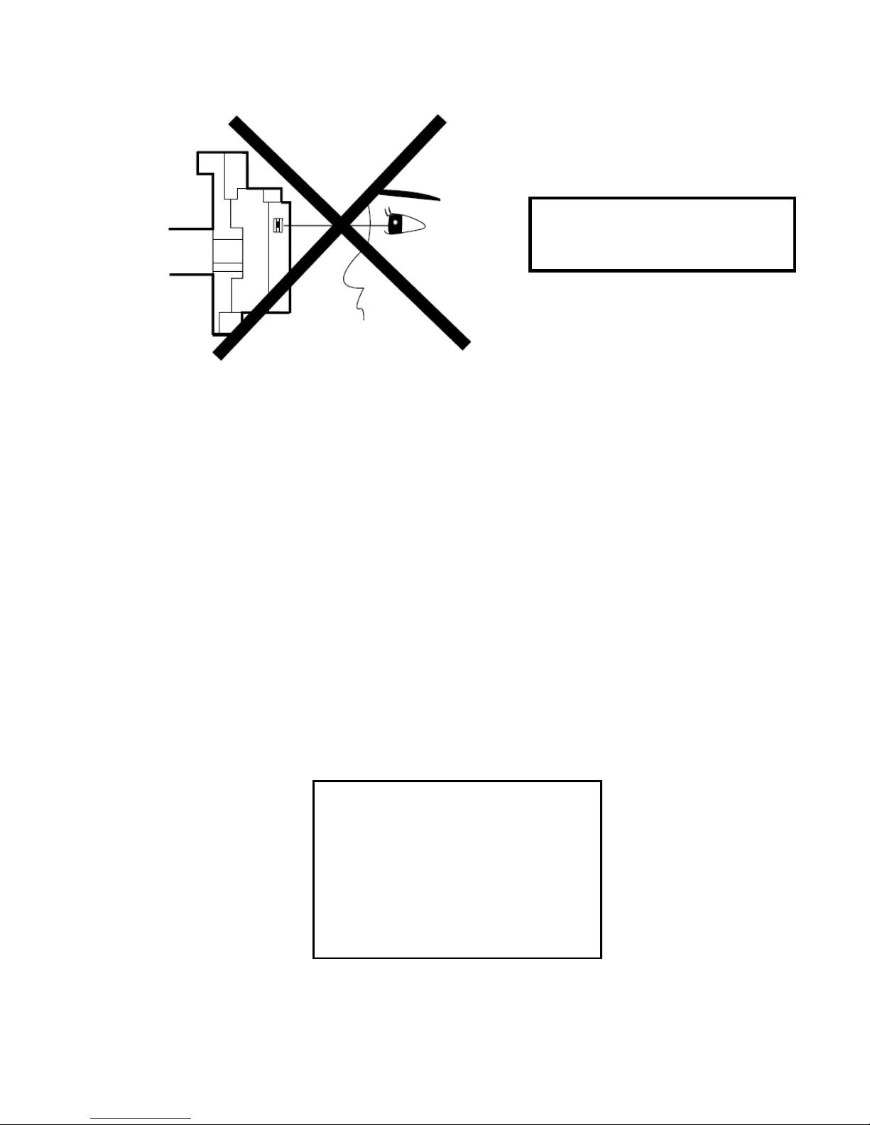
This DVD player uses a pickup that emits a laser beam.
Do not look directly at the laser beam
coming from the pickup or allow it to
strike against your skin.
The laser beam is emitted from the location shown in the figure. When checking the laser
diode, be sure to keep your eyes at least 30 cm away from the pickup lens when the diode is
turned on. Do not look directly at the laser beam.
CAUTION: Use of controls and adjustments, or doing procedures other than tho se specified
herein, may result in hazardous radiation exposure.
CAUTION
LASER RADIATION
WHEN OPEN. DO NOT
STARE INTO BEAM.
Location: Top of DVD mechanism.
1 - 2
STANDARD NOTES FOR SERVICING
Instructions for Connectors
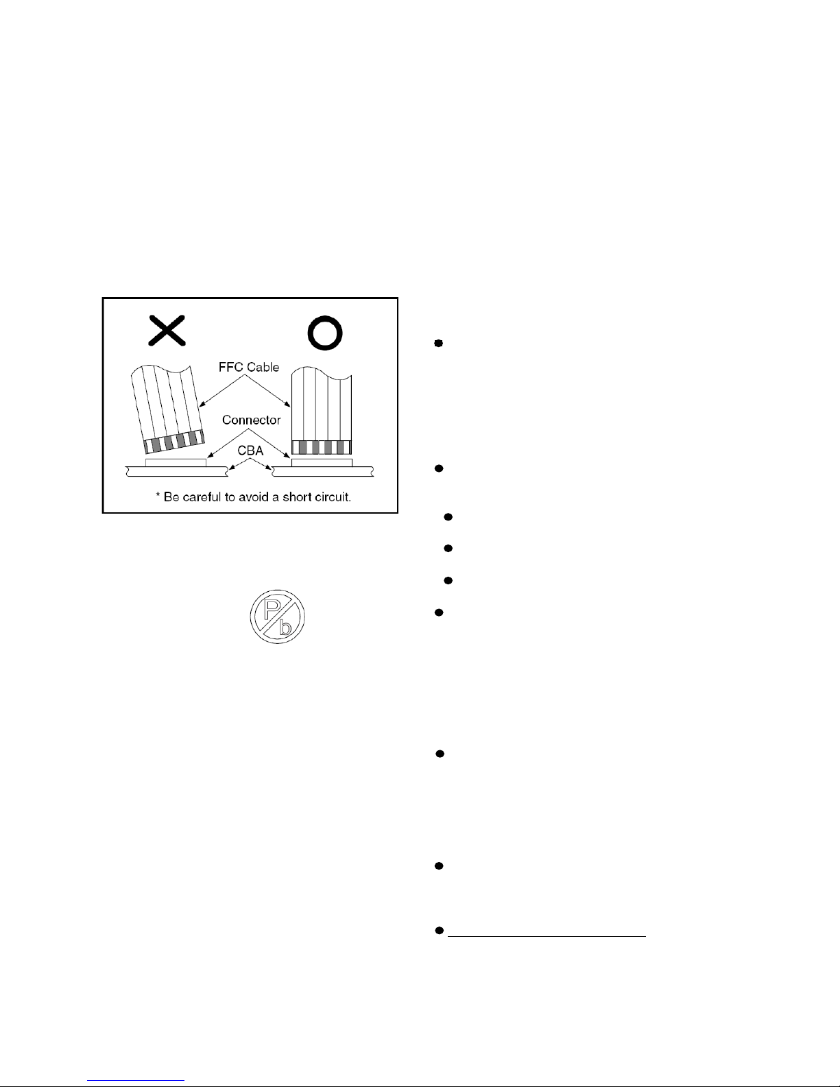
1. When you connect or disconnect the FFC
(Flexible Foil Connector) cable, be sure to first
disconnect the AC cord.
2. FFC (Flexible Foil Connector) cable should
be inserted parallel into the connector, not at
an angle.
Pb (Lead) Free Solder
When soldering, be sure to use the Pb free
solder.
IDENTIFICATION:
Regardless of special logo (not always
indicated
One must treat all sets from 1.1.2005
onwards, according next rules.
)
Important note: In fact also products a little
older can also be treated in this way as long as
you avoid mixing solder-alloys (leaded/
lead-free). So best to always use SAC305 and
the higher temperatures belong to this.
Due to lead-free technology some rules have
to be
respected by the workshop during a repair:
Use only lead-free solder alloy Philips
SAC305 with order code 0622 149 00106. If
lead-free solder paste is required, please
contact the manufacturer of your
solder-equipment. In general use of solder
paste within workshops should be avoided
because paste is not easy to store and to
handle.
Use only adequate solder tools applicable
for leadfree solder alloy. The solder tool must
be able
To reach at least a solder-temperature of
400°C,
To stabilize the adjusted temperature at
the solder-tip
To exchange solder-tips for different
applications.
Adjust your solder tool so that a temperature
around 360°C - 380°C is reached and
stabilized at the solder joint. Heating-time of
the solder-joint should not exceed ~ 4 sec.
Avoid temperatures above 400°C otherwise
wear-out of tips will rise drastically and
flux-fluid will be destroyed. To avoid wear-out
of tips switch off un-used equipment, or
reduce heat.
Mix of lead-free solder alloy / parts with
leaded solder alloy / parts is possible but
PHILIPS recommends strongly to avoid mixed
solder alloy types (leaded and lead-free). If
one cannot avoid, clean carefully the
solder-joint from old solder alloy and re-solder
with new solder alloy (SAC305).
Use only original spare-parts listed in the
Service-Manuals. Not listed standard-material
(commodities) has to be purchased at external
companies.
Special information for BGA-ICs:
- always use the 12nc-recognizable soldering
temperature profile of the specific BGA (for
desoldering always use highest lead-free
1 - 3
temperature profile, in case of doubt)
- lead free BGA-ICs will be delivered in
so-called 'dry-packaging' (sealed pack
including a silica gel pack) to protect the IC
against moisture. After opening, dependent of
MSL-level seen on indicatorlabel in the bag,
the BGA-IC possibly still has to be
baked dry. This will be communicated via
AYS-website.
Do not re-use BGAs at all.
For sets produced before 1.1.2005,
containing leaded soldering-tin and
components, all needed spare-parts will be
available till the end of the service-period. For
repair of such sets nothing changes.
On our website
www.atyourservice.ce.Philips.com
more information to:
BGA-de-/soldering (+ baking instructions)
Heating-profiles of BGAs and other ICs
used in Philips-sets.
You will find this and more technical
information within the “magazine”, chapter
“workshop news”.
For additional questions please contact your
local repair-helpdesk.
you find
How to Remove / Install Flat
Pack-IC
1. Removal
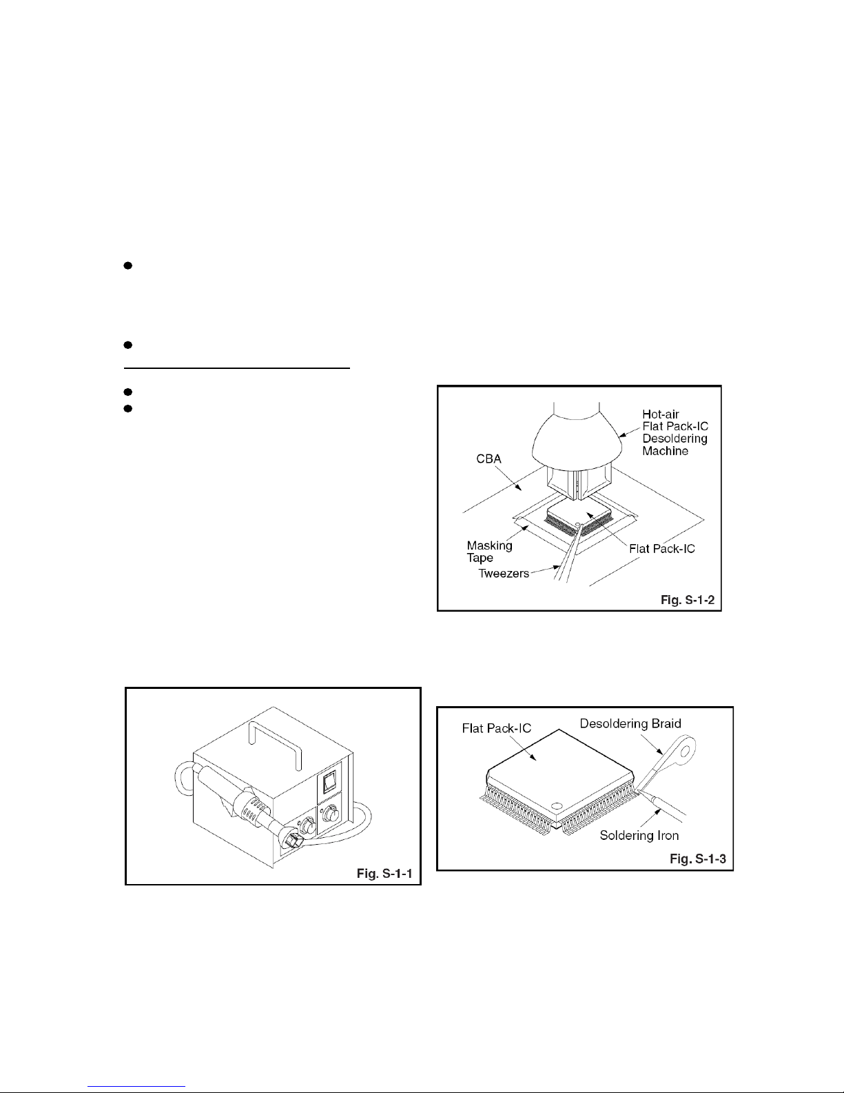
With Hot-Air Flat Pack-IC Desoldering
Machine:
1. Prepare the hot-air flat pack-IC desoldering
machine, then apply hot air to the Flat Pack-IC
(about 5 to 6 seconds). (Fig. S-1-1)
be melted). (Fig. S-1-6)
4. Release the flat pack-IC from the CBA using
tweezers. (Fig. S-1-6)
CAUTION:
1. The Flat Pack-IC shape may differ by
models. Use an appropriate hot-air flat
pack-IC desoldering machine, whose shape
matches that of the Flat Pack-IC.
2. Do not supply hot air to the chip parts
around the flat pack-IC for over 6 seconds
because damage to the chip parts may occur.
Put masking tape around the flat pack-IC to
protect other parts from damage. (Fig. S-1-2)
3. The flat pack-IC on the CBA is affixed with
glue, so be careful not to break or damage the
foil of each pin or the solder lands under the IC
when removing it.
With Soldering Iron:
1. Using desoldering braid, remove the solder
from all pins of the flat pack-IC. When you use
solder flux which is applied to all pins of the flat
pack-IC, you can remove it easily. (Fig. S-1-3)
2. Remove the flat pack-IC with tweezers while
applying the hot air.
3. Bottom of the flat pack-IC is fixed with glue
to the CBA; when removing entire flat pack-IC,
first apply soldering iron to center of the flat
pack-IC and heat up. Then remove (glue will
2. Lift each lead of the flat pack-IC upward one
by one, using a sharp pin or wire to which
solder will not adhere (iron wire). When
heating the pins, use a fine tip soldering iron or
a hot air desoldering machine. (Fig. S-1-4)
1 - 4

3. Bottom of the flat pack-IC is fixed with glue
to the CBA; when removing entire flat pack-IC,
first apply soldering iron to center of the flat
pack-IC and heat up. Then remove (glue will
be melted). (Fig. S-1-6)
4. Release the flat pack-IC from the CBA using
tweezers. (Fig. S-1-6)
With Iron Wire:
1. Using desoldering braid, remove the solder
from all pins of the flat pack-IC. When you use
solder flux which is applied to all pins of the flat
pack-IC, you can remove it easily. (Fig. S-1-3)
2. Affix the wire to a workbench or solid
mounting point, as shown in Fig. S-1-5.
3. While heating the pins using a fine tip
soldering iron or hot air blower, pull up the wire
as the solder melts so as to lift the IC leads
from the CBA contact pads as shown in
Fig.S-1-5.
4. Bottom of the flat pack-IC is fixed with glue
to the CBA; when removing entire flat pack-IC,
first apply soldering iron to center of the flat
pack-IC and heat up. Then remove (glue will
be melted). (Fig. S-1-6)
5. Release the flat pack-IC from the CBA using
tweezers. (Fig. S-1-6)
Note: When using a soldering iron, care must
be taken to ensure that the flat pack-IC is not
being held by glue. When the flat pack-IC is
removed from the CBA, handle it gently
because it may be damaged if force is applied.
2. Installation
1. Using desoldering braid, remove the solder
from the foil of each pin of the flat pack-IC on
the CBA
so you can install a replacement flat pack-IC
more easily.
2. The “●” mark on the flat pack-IC indicates
pin 1. (See Fig. S-1-7.) Be sure this mark
matches the 1 on the PCB when positioning
for installation. Then presolder the four
corners of the flat pack-IC. (See
Fig. S-1-8.)
3. Solder all pins of the flat pack-IC. Be sure
that none of the pins have solder bridges.
1 - 5
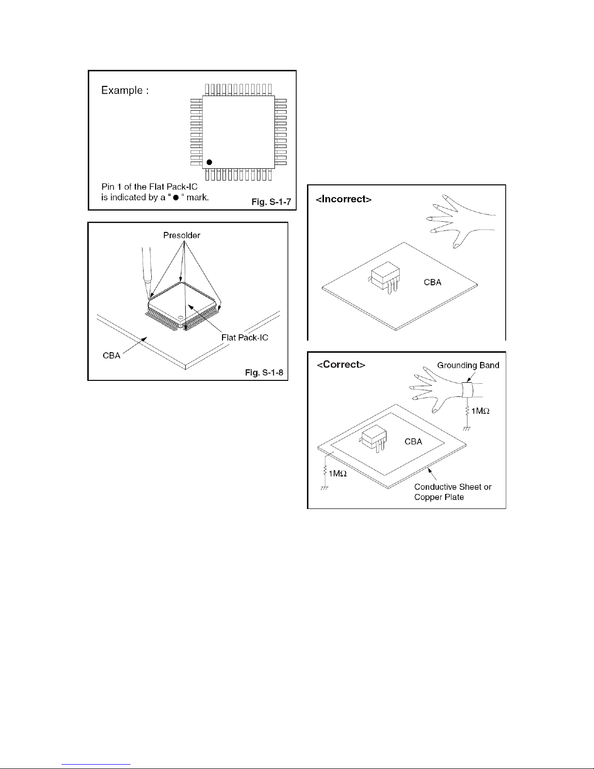
2. Ground for Workbench
Be sure to place a conductive sheet or copper
plate with proper grounding (1 M∧) on the
workbench or other surface, where the
semi-conductors are to be placed. Because
the static electricity charge on clothing will not
escape through the body grounding band, be
careful to avoid contacting semi-conductors
with your clothing.
Instructions for Handling
Semiconductors
Electrostatic breakdown of the
semi-conductors may occur due to a potential
difference caused by electrostatic charge
during unpacking or repair work.
1. Ground for Human Body
Be sure to wear a grounding band (1 M∧) that
is properly grounded to remove any static
electricity that may be charged on the body.
1 - 6
Safety and important notice
W
arning
•
Risk of overheating! Never install the Home
Theater Syste
m in a confi ned space. Always
leave a space of at least 4 inches around the
Home Theater System for ventilation. Ensure
curtains or other objects never cover the
ventilation slots on the Home Theater System.
• Never place the Home Theater System,
remote control or batteries near naked fl ames
or other heat sources, including direct sunlight.
• Only use this Home Theater System indoors.
Keep this Home Theater System away from
water, moisture and liquid-fi lled objects.
• Never place this Home Theater System on
other electrical equipment.
• Keep away from this Home Theater System
during lightning storms.
• Where the mains plug or an appliance
coupler is used as the disconnect device,
the disconnect device shall remain readily
operable.
• Visible and invisible laser radiation when open.
Avoid exposure to beam.
Recy
cle notice
This electronic equipment contains a large
number of materials that can be recycled
or reused if disassembled by a specialized
company. If you are disposing of an old
machine, please take it to a recycling center.
Please observe the local regulations regarding
disposal of packaging materials, exhausted
batteries and old equipment.
Co
pyright notice
This product incorporates copyright
protection technology that is protected
by method claims of certain U.S. patents
and other intellectual property rights
owned by Macrovision Corporation and
other rights owners. Use of this copyright
protection technology must be authorised
by Macrovision Corporation, and is intended
for home and other limited viewing uses only
unless otherwise authorised by Macrovision
Corporation. Reverse engineering or
disassembly is prohibited.
About Progressive Scan
Consumers should note that not all high
defi nition television sets are fully compatible
with this product and may cause artifacts to
be displayed in the picture. In case of 525
or 625 progressive scan picture problems,
it is recommended that the user switch the
connection to the ‘standard defi nition’ output.
If there are questions regarding our TV set
compatibility with this model 525p and 625p
DVD player, please contact our customer
service center.
1 - 7
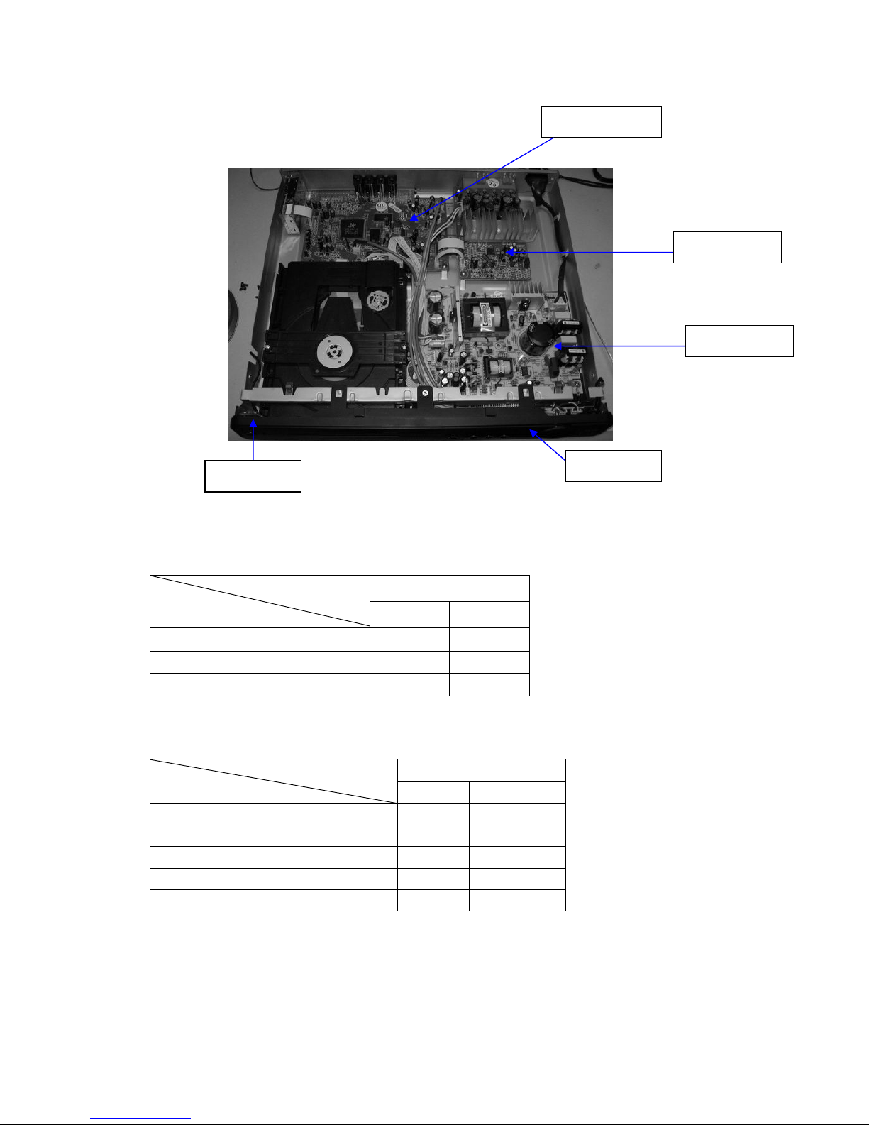
LOCA
TION OF PCB BOARDS
VERSION V
ARIA T ION:
HTS3172
T
ype/Versions
Features
/93 /98
Output Pow
er-200W
Χ Χ
V
oltage(220V-240V)
Χ Χ
MP3 Link
Χ Χ
SER
VICE SCNARIO MATRIX:
HTS3172
T
ype/Versions
Board in used
/93 /98
DECODE board C C
POWER board C C
AMP
board C C
LED board
C C
KEY
board C C
*C=Com ponent Level Repair
KEY
BOARD
LED BOARD
POWER BOAR
D
AM
P BOARD
DECODE BOARD
2 - 1

(Open/Close )
• Opens or closes the disc
compartment.
Source buttons
• AUDIO SOURCE : Selects an audio
input source.
• RADIO : Switches to FM band.
• USB : Switches to the USB source.
• DISC : Switches to the disc source.
SETUP
• Accesses or exits the setup menu.
(Navigation buttons )
• Navigates through the menus.
• Press left and right for fast backward
or forward search.
• In radio mode, press up and down to
tune the radio frequency.
• In radio mode, press left or right to
start auto search.
INFO
• For discs, displays information about
the current status or the disc.
•
For slideshows, displays a thumbnail
view of photo
fi
les.
(Play/Pause )
• Starts, pauses or resumes disc play.
• In radio mode, automatically tunes
radio stations during
fi
rst-time setup.
(Stop )
•
Stops disc play.
• In radio mode, erases the current
preset radio station.
SURR (Surround Sound)
• Switches to supported surround
sound or stereo sound.
AUDIO SYNC
• Selects an audio language or channel
on a disc.
• Press and hold to access the setting
for audio sync, then press VOL +/- to
set the audio delay time.
Numeric buttons
• Selects an item to play.
SUBTITLE
• Selects the subtitle language on a
disc.
VOCAL
• Changes the audio channel of a
karaoke disc.
MIC (VOL +/-)
• Increases or decreases microphone
volume.
REPEAT / PROGRAM
• Selects or turns off repeat or shuf
fl
e
mode.
• In radio mode, resets the list of
preset stations: press to manually
reset; press and hold to automatically
reset.
OK
•Con
fi
rms an entry or selection.
BACK
• Returns to a previous screen.
• For DVD, goes to the title menu.
• For VCD version 2.0 or SVCD with
PBC turned on, returns to the menu
during playback.
(Previous/Next )
• Skips to the previous or next title,
chapter, or track.
(Mute )
• Mutes or restores audio output.
VOL +/-
• Increases or decreases volume.
SOUND
• Selects a prede
fi
ned sound effect.
ZOOM
• Zooms in or out of the picture.
• Fits the picture format to the TV
screen.
KARAOKE
• Accesses or exits the karaoke menu.
Your Home
Englis
h
Standby-On
•
Turns on the Home Theater System
or switches to standby mode.
(
)
Remote Control
2 - 2
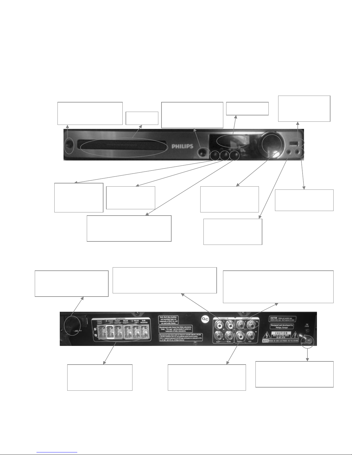
OPERATING
CONTROLS AND FUNCTIONS
Front Panel
Back Panel
MAINS~(AC Power
cord)
—Connect to a standard
AC outlet
AUDI
O IN
—Connect the audio cables(not supplied)
to the AUDIO IN_AUX1 jacks
ANTENNA
—Connec
t the FM antenna to
the FM 75Ωjack
SPEAKERS
—Connec
t the Speakers
to the matching jacks
VIDEO
—Con
nect a composite video
cable to the video jack
VIDEO O
UT
—Connect the component video cable(not
supplied) to the Y Pb Pr jacks
VOLUME
—
Increas
es or
decreases volume.
Displa
y Panel
Disc T
ray
Standb
y-On
—
T
urns on the player or
switches to standby mode
SOURCE
—
Selects
a media to play or listen to
audio from the connected device.
Open/Close
—
Opens or closes the disc
com
partment.
USB
— Connects
a USB
supported device
St
op
—Stops playback
Play
/Pause
—starts or pa
uses
playback
MP3 LINK
—Connects
a portable
audio player
MIC
—
Connects
a microphone
2 - 3

SPECIFICATIONS
AMPLIFIER
Total output power :
- Home Theatre mode .................................... ............... 200 W
Frequency
Response .........................………….180Hz – 18kHz / ±3 dB
Signal-to-Noise Ratio ..........................................>- 60 dB (A-weighted)
Input Sensitivity
- AUX1………........................................................................500 mV
- AUX2……………… .......................................................... 500 mV
- MP3 LINK .......................................................................... 500 mV
RADIO
Tuning Range ...........................................................FM 87.5-108
MHz
..................................................................................................(50 kHz)
.......................................................................................26 dB Quieting
Sensitivity ...........................................................................FM 22 dBf,
IF Rejection Ratio .................................................................FM 50 dB
Signal-to-Noise Ratio ...........................................................FM 30 dB
Harmonic Distortion ..................................................... FM Mono 3%
.................................................................................................. FM 3%
Frequency Response ............................... FM 180 Hz–10 kHz / ±3 dB
Stereo Separation ................................................... FM 26 dB (1 kHz)
Stereo Threshold ...............................................................FM 23.5 dB
DISC
Laser Type ......................................................... …...Semiconductor
Disc Diametre .................................................................12cm / 8cm
Video Decoding .....................................MPEG-1 / MPEG-2 /DivX
..................................................................................... / DivX Ultra
Video DAC .............................................................12 Bits,108MHz
Signal System ............................................................PAL / NTSC
Video S/N ............................................................................ 56 dB
Audio DAC............................................................. 24bits/96KHz
Frequency Response ............................. 4 Hz–20 kHz (44.1 kHz)
................................................................ ..4 Hz–22 kHz (48 kHz)
.................................................................. 4 Hz–44 kHz (96 kHz)
PCM ........................................................................... IEC 60958
Dolby Digital .......................................... IEC 60958, IEC 61937
MAIN UNIT
Power
Supply
-For China……………………………………….. 220 - 230 V~50Hz;
-For Asia Pacific……………………………...110 - 240 V~50-60Hz
Standby power consumption...........................................................<1W
Power Consumption ........................................................ 50 W
Dimensions ............................................... 360 x 48 x 332 (mm)
...................................................................................(w x h x d)
Weight ..............................................................................2.64 kg
SPEAKERS
System ..................... ............................. ........ Full range satellite
Sp
eaker impedance ............................8 ohm(centre),4 ohm(Front/Rear)
Speaker drivers .................................................... 3” full range speaker
Frequency response ...................................................150 Hz – 20 kHz
Dimensions:
-Center……………………………………..266.6 x102.3 x78 (mm)
-Front………………………………………...100 x284.5 x78 (mm)
-Rear…………………………………………. 100 x 100x 75 (mm)
...............................................................................................(w x h x d)
Weight:
-Center…………………………………………………..…0.68kg
-Front………………………………………………. .0.66 kg/each
-Rear………………………………………………….0.38 kg/each
USB
Co
mpatibility .......................................................... USB
Class support ......................................... UMS(USB Mass storage Class)
File system........................................FAT12,FAT16,FAT32
SUBWOOFER
Impedance ............................... ... ... ... .................................8 oh m
Speaker drivers ........................................ 165mm (6.5”) woofer
Frequency response ..........................................45Hz – 150 Hz
Dimensions ........................................ 162.5x 362.5 x 369 (mm)
...................................................................................(w x h x d)
Weight ............................................................................4.53kg
Laser specification
Type..............................................Se
miconductor laser GaAlAs(CD)
Wave length................................. 645-665nm (DVD) 770-800nm(CD)
Ou
tput power ........................................6Mw(DVD) 7Mw(VCD/CD)
Beam divergence........................................ 60 degrees
.
3 - 1
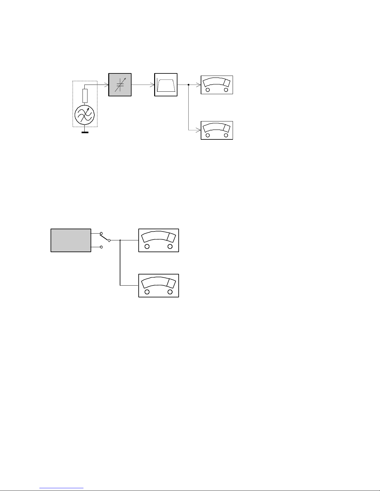
MEAS
UREMENT SETUP
Tuner FM
DU
T
B
andpass
20Hz-15kHz
LF Voltm
eter
RF Generator
e.
g. PM5326
e.g. 7122 707 48001
e.g. PM2534
S/
N and distortion meter
e.g. Sound Technology ST1700B
Use a b
andpass filter to eliminate hum (50Hz, 100Hz) and disturbance from the pilottone (19kHz, 38kHz).
CD
Use
Audio Signal Disc
(replaces test disc 3)
DU
T
L
R
SBC4
29 4822 397 30184
S/
N and distortion meter
e.
g. Sound Technology ST1700B
LEVEL
METER
e.g
. Sennheiser UPM550
with F
F-filter
Ri=7
5Ω
3 - 2
System , Region Code , etc. Setting Produre
1)System Reset
a) Press “SETUP“ button on RC,TV will show setup menu
b) Select the menu using the and on RC
c) Go preference page to do system reset
2)Region Code Change
a) In open model, press”9” “9“ “9“ “9“ on R/C,then input desired
number to change region code :
1 USA
2 EU
3 AP
4 Australia ,NZ , Latam
5 Russia , INDIA
6 CHINA
3)Version Control Change
a) In open model, press “1“ “5“ “9“ on RC
c) Press and “ok” button to con rm
d) TV will show message as below:
7) Upgrading new sofeware
a) Copy “sofeware les” into a CD-R or USB flash drive.
b) Insert the CD-R disc or USB flash drive.
c) Press DISC or USB, the system will identify the update file autometically.
d) VFD will show
“Updating“ until update is complete.
* the system will switch off to standby automatically after update is complete.
e) OSD will show:
Current model
HTS3172/98
Ver18.04.2M _ 090211_0 region
: 3
Servo: AE.56.00.00
8032: 05.00.04.06 RISC: 05.02.00.24
IF current model does not match you set use down arrow
key on the remote to change
OK
CAUTION!
This information is confi dential and may not be
distributed.Only a qualifi ed se rvice person should
reprogram the Region Code.
4)Password Change
a) Press “SETUP“ button on R/C,TV will show setup menu
b) Select the menu using the and on RC
c) Go preference page select “password“ to change
* 136900 is default password supplied.
5)Check on the Sofeware Version
TV will show the version on screen.
6)Trade model
a) Press “Open/Close “ button on RC
b) Press “2” “5” “9” on R/C,VFD will display “TRA ON “ or “TRA
OFF“
b) Press and select version you want using
a) Press “SETUP“ button on R/C,TV will show setup menu
b) Select the menu using the and on RC
c) Go preference page select “Version Info“.
/93
3 - 3
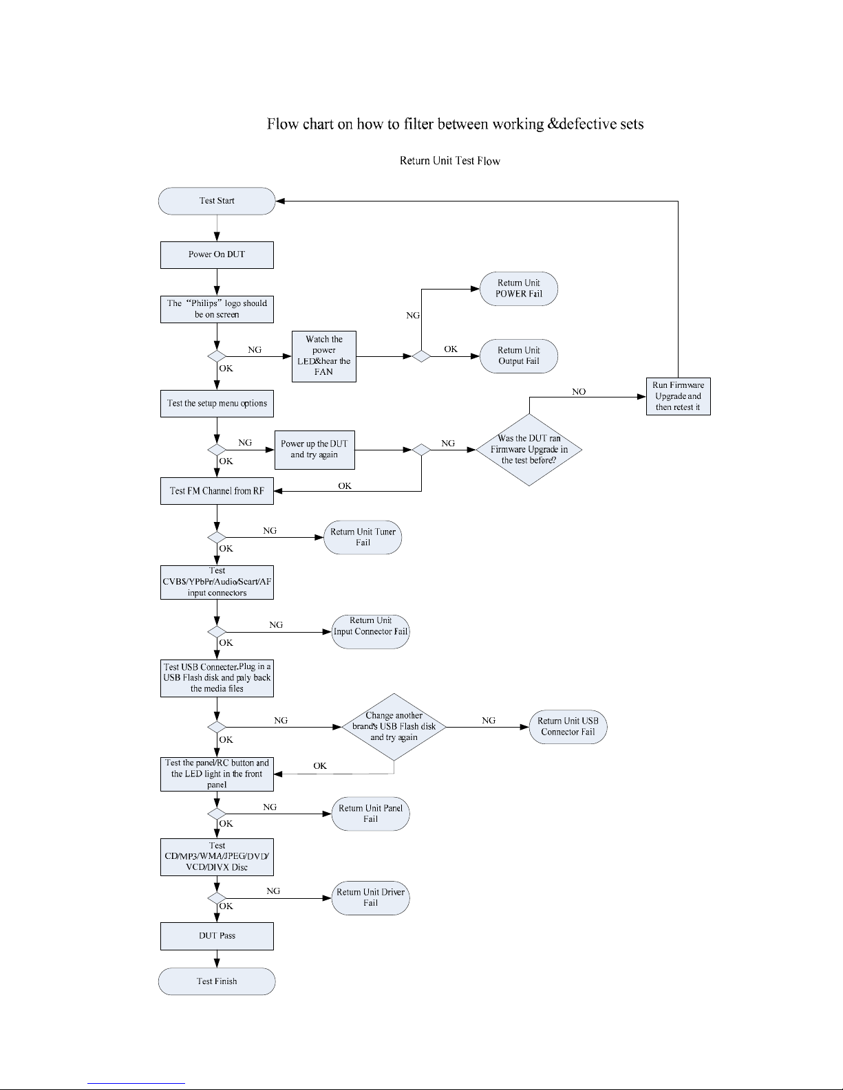
3 - 4

F
A
AII F
unction NO Working
Check AII S
ystem, AII Coble
is Loose or bad: INT
RE-insert and
fix the
cable
Panel st
and LED show
working or Not
Check Ba
ck Power PCB
F901 Bad cause Damage
Change F901
Check Con902
pin1
+5V affirm Correct
Rep
air between T901
Circuit
Check control PCB
IC901 an
d their conjoint
Part
Check CON
903 PIN2
M5V affirm Correct
Check Sw
itch power
Supply Circuit
Check Rep
air
U102,U104,U105,U106
Circuit
E
F
B
Power suppl
y NO
Working
+27V V
oltage No
Output
Check F901 Bad
Cause Damage
Check ic901
W
orking Or Not
Check po
wer
Transformer Working
Or Not
ALL
voltage No
output
+5V V
oltage No
Output
+/-12v V
oltage No
Output
Check cn801 vcc
Voltage=27V
Check D91
1 D912
and its conjoint part
Check D908 D
910
and its conjoint part
Check Q901 and
its
conn circuit
Rep
air The Part
R
epair The part
Check Rep
air D905 and
conn circuit
C
Check D916 an
d its
conjoint part
ALL
Function No
Sound
Check ic801a ic801b pin
23 Voltage is 3.3v
Check IC801A
IC801B
Voltage correct is ok
See Content
s B
Check rep
air D916 and its
conjoint part
Check r
epair Q804=3.3V
and its conjoint part
DVD Audio no
t
sound
Check open/close and disc
change w
orking or not
Re-insert and
fix the
cable
Hae picture out
put Yes
or No
Check IC u102 AND
con100 its conjoint part
Check cn102 cn101and
cn105 to dvd loader,
cable loose or bad int
Check U102 and their
cojoint part
Check cn102 to DVD
loader loose or b
ad not
Check ic804 their
conjoint p
art
Check rep
air Between
ic801
E
Aux
/TV in No
Sound
T
uner NO Sound
Check U109 an
d its conjoint
part offirm working
Check rep
air Between
L131=5V and their conjoint
part
Check U107 U
108 and its
conjoint part offirm working
Check U107 U1
08 PIN7=-5.1
pin16=+5V
Check betwe
en U102
PIN162 163 164 and their
cojoint part
Check cn1
11
pin9=9V
According AUX/
TV
REPAIR
Check IC1
12 PIN4=-12V
PIN8=+12V and other
conjoint part
Check u102 PI
N198 199 200
and pin201 other conjoint part
Alternate tune
r
Check D101
V
oltage=10.1v
Check Q101
and
their conjoint part
Check servo pcb
Check U100 PIN
2 1V8
Check U101 PIN2 3V3
D
Check U102 PIN109,210,2
11and
214 its conjoint part
AII Function NO
Working
Power supply NO
working
ALL Function NO
Sound
Aux/TV in NO
Sound
Tuner NO Sound
YES
not bad
no
ok
not
ok
not
not
ok
not
YES
ALL
voltage No
output
YES
wo
rkin
g
not
not
notnot
not
not
not
y
es
y
es
not
not
not
not
ok
ok
ok
YES
YES
not
not
ok
not
ok
not
not
not
D
DVD Audio NO
Sound
A
MAIN UN
IT REPAIR CHART
B
C
3 - 5
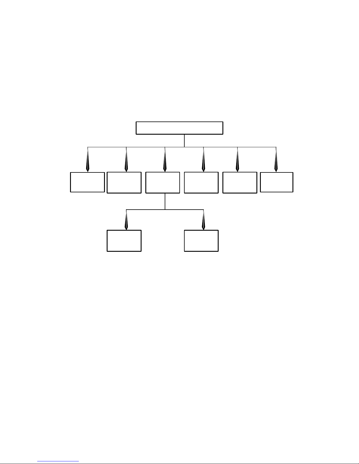
DISASSEMBL
Y INSTRUCTIONS
1. Disassemb
ly Flowchart
Thi
s flowchart indicates the disassembly steps to gain access to item(s) to be serviced. When
reassembling, follow the steps in reverse order. Bend, route, and dress the cables as they were
originally.
Top Case
Lo
ader
Board
Led
Board
Fr
ont
Panel
Po
wer
Board
Board
Am
plifier
Board
Tu
ner
De
code
Key
4 - 1
 Loading...