

Page 1

1 - 1
BD Home Theater System
HTB7250D_HTB7255D/12
Service
Service Manual
under license.
TABLE OF CONTENTS
Location of PCB Boards ............................................ 1-2
Versions Variation ...................................................... 1-2
Specifications ............................................................ 1-3
Measurement Setup .................................................. 1-6
Service Aids .............................................................. 1-7
ESD & Safety Instruction .......................................... 1-8
Lead-free Soldering Information ................................ 1-9
Setting Procedure & Repair Instructions ...................... 2
Disassembly Instructions & Service Positions .............. 3
Block & Wiring Diagram ................................................ 4
MAIN+VFD+SUB+USB+MP3+SENSOR+BT Board .... 5
BD Board........................................................................ 6
Touch Board .................................................................. 7
Power Board(Subwoofer) ............................................ 8
Mechanical Exploded View............................................ 9
Revision List ................................................................ 10
Chapter
©
Copyright 2013Philips Consumer Electronics B.V. Eindhoven, The Netherlands
All rights reserved. No part of this publication may be reproduced, stored in a retrieval system or
transmitted, in any form or by any means, electronic, mechanical, photocopying, or otherwise
without the prior permission of Philips.
Published by SL_HF1305 Service Audio Printed in The Netherlands Subject to modification
Version 1.1
GB
3141 785 39441
Page 2
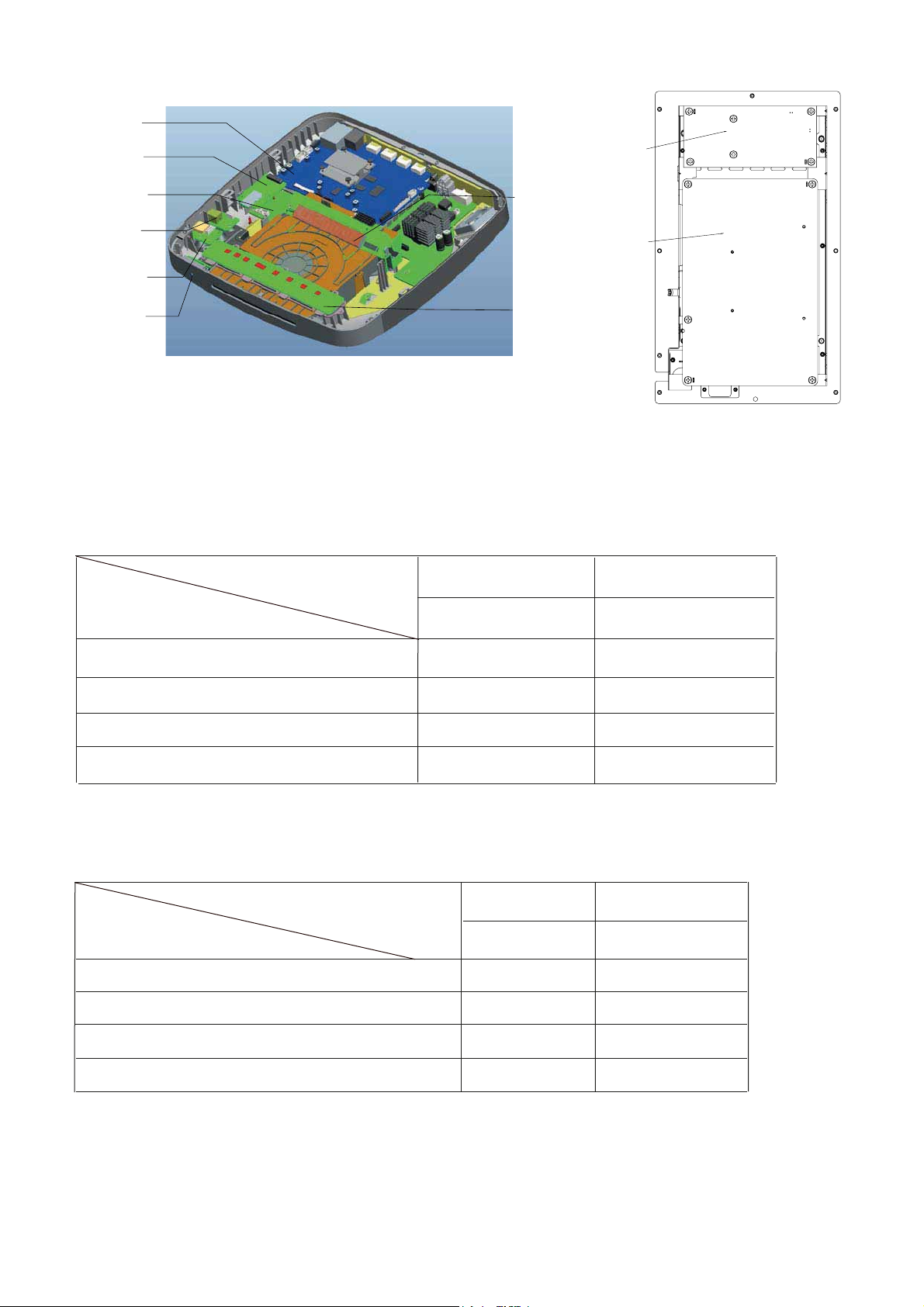
LOCATION OF PCB BOARDS
BD PCB
1 - 2
BT PCB
MAIN PCB
MP3 PCB
USB PCB
SENSOR PCB
Main Unit
VERSION VARIATION:
Type/Versions
VFD PCB
TOUCH PCB
HTB7250D
SUB PCB(AMPPCB)
SUB _POWR CPB
Subwoofer
HTB7255D
Features
Output Power - 500W
Voltage (220~240V)
Bluetooth
Subwoofer
SERVICE SCENARIO MATRIX:
Type/Versions
Board in used
MAIN+VFD+SUB+USB+MP3+SENSOR+BT Board
Power Board(subwoofer)
BD Board
Touch Board
/12
x
x
x
x
HTD7250D
/12
C
C
Bd
Bd
/12
x
x
x
x
HTD7255D
/12
C
C
Bd
Bd
*Bd= Board Level Replacement
*C = Component Level Repair
Page 3
SPECIFICATIONS
1 - 3
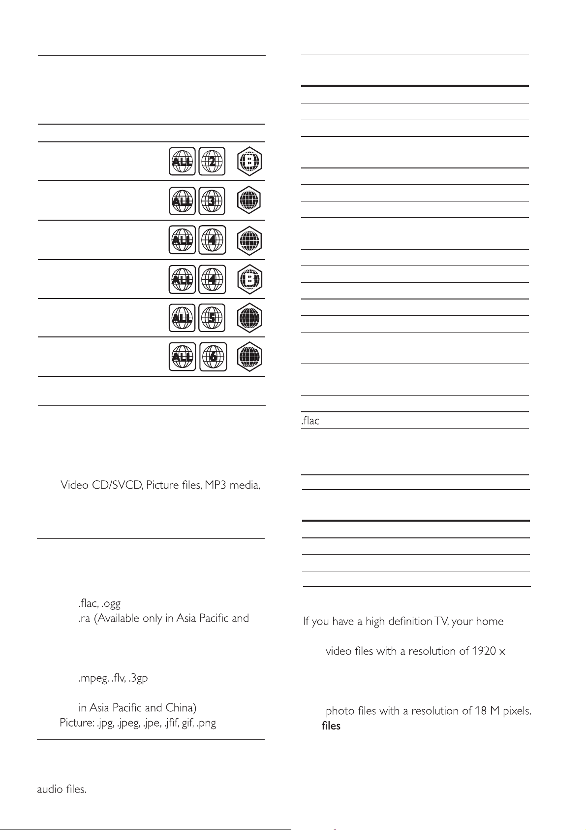
Region codes
The type plate on the back or bottom of the
home theater shows which regions it supports.
Country
Europe,
United Kingdom
Asia Pacific, Taiwan,
Korea
Latin America
Australia,
New Zealand
Russia, India
DVD BD
AA
AA
CC
China
CC
Media formats
• AVCHD, BD, BD-R/ BD-RE, BD-Video,
DVD-Video, DVD+R/+RW, DVD-R/-RW,
DVD+R/-R DL, CD-R/CD-RW, Audio CD,
Extension Con-
tainer
.mp3 MP3 MP3 Upto 320 kbps
.wma ASF WMA Upto 192 kbps
.aac AAC AAC, HE-
.wav WAV PCM 27.648 Mbps
.m4a MKV AAC 192 kbps
.mka MKA PCM 27.648 Mbps
.ra RM AAC, HE-
FLAC FLAC Upto 24 bps
.ogg OGG Vorbis Variable bit rate,
Audio
codec
WMA Pro Upto 768 kbps
AAC
Dolby
Digital
DTS core 1.54 Mbps
MPEG 912 kbps
MP3 Upto 320 kbps
WMA Upto 192 kbps
WMA Pro Upto 768 kbps
AAC, HE-
AAC
AAC
Cook 96469 bps
Bit rate
Upto 192 kbps
640 kbps
Upto 192 kbps
Upto 192 kbps
maximum block
size 4096
WMA media, DivX Plus HD media, USB
storage device
File formats
• Audio:
• .aac, .mka, .mp3, .wma, .wav, .mp4, .m4a,
•
China)
• Video:
• .avi, .divx, .mp4, .m4v, .mkv, .m2ts, .mpg,
• .asf, .wmv, .rmvb, .rm, .rv (Available only
•
Audio formats
Your home theater suppor ts the following
Extension Con-
tainer
Video formats
theater allows you to play your:
•
1080 pixels (except DivX, which has a
resolution of 77220 x 576) and frame rate
of 6 ~ 30 frames per second.
•
.avi in AVI container
Audio
codec
FLAC Upto 24 bps
OGGPCM No limit
MP3 Upto 320 kbps
Bit rate
Page 4
1 - 4
Audio
codec
PCM,
Dolby
Video codec Bit rate
DivX 3.11, DivX 4.x,
DivX 5.x, DivX 6.x
10 Mbps
max
Digital,
DTS core,
MP3,
WMA
MPEG 1, MPEG 2 40 Mbps
MPEG 4 SP / ASP 38.4
Mbps
H.264/AVC upto
25 Mbps
HiP@5.1
WMV9 45 Mbps
.divx
Audio codec Video codec Bit rate
PCM, Dolby
Digital, MP3,
WMA
in AVI container
DivX 3.11,
DivX 4.x, DivX 5.x,
DivX 6.x
10
Mbps
max
Audio codec Video codec Bit rate
PCM, Dolby Digital,
DTS core, MPEG,
MPEG 1,
MPEG 2
40 Mbps
MP3, WMA, AAC,
HE-AAC, DD+
MPEG 4 ASP 38.4
Mbps
H.264/AVC
25 Mbps
HiP@5.1
WMV9 45 Mbps
.asf and .wmv
only in Asia
Audio codec Video codec Bit rate
Dolby Digital,
in ASF container (Available
and China)
MPEG 4 ASP 38.4 Mbps
MP3, WMA,
DD+
H.264/AVC
25 Mbps
HiP@5.1
WMV9 45 Mbps
.mp4 or .m4v
Audio codec Video codec Bit rate
Dolby Digital,
MPEG, MP3,
in MP4 container
MPEG 1,
MPEG 2
40 Mbps
AAC, HE-AAC,
DD+
MPEG 4 ASP 38.4
Mbps
H.264/AVC
25 Mbps
HiP@5.1
.mkv
Audio codec Video codec Bit rate
PCM, Dolby
in MKV container
DivX Plus HD 30 Mbps
Digital, DTS core,
MPEG, MP3,
WMA, AAC, HEAAC, DD+
MPEG 1, MPEG 240 Mbps
MPEG 4 ASP 38.4
Mbps
H.264/AVC
25 Mbps
HiP@5.1
WMV9 45 Mbps
.m2ts
in MKV container
.mpg and .mpeg
Audio codec Video codec Bit rate
PCM, DTS core,
MPEG, MP3
in PS container
MPEG 1,
MPEG 2
40
Mbps
in FLV container
Audio
codec
MP3,
AAC
Video codec Bit rate
H.264/AVC upto
25 Mbps
HiP@5.1
H.263 38.4 Mbps
On2 VP6 40 Mbps
.3gp in 3GP container
Audio
codec
AAC, HE-
Video codec Bit rate
MPEG 4 ASP 38.4 Mbps
AAC
H.264/AVC upto
HiP@5.1
.rm, .rv, and .rmvb
in RM container
(Available only in Asia
Audio codec Video codec Bit rate
25 Mbps
max
and China)
AAC, COOK RV30, RV40 40 Mbps
Page 5
1 - 5
Subwoofer
• Total output power: 500W RMS (+/- 0.5
dB, 30% THD) / 400W RMS (+/- 0.5 dB,
10% THD)
• Frequency response: 20 Hz-20 kHz / ±3
dB
• Signal-to-noise ratio: > 65 dB (CCIR) /
(A-weighted)
• Input sensitivity:
• AUX: 650 mV
• AUDIO-IN: 300 mV
Video
• Signal system: PAL / NTSC
• HDMI output: 480i/576i, 480p/576p, 720p,
1080i, 1080p, 1080p24
Audio
• S/PDIF Digital audio input:
• Optical: TOSLINK
• Sampling frequency:
• MP3: 32 kHz, 44.1 kHz, 48 kHz
• WMA: 44.1 kHz, 48 kHz
• Constant bit rate:
• MP3: 32 kbps - 320 kbps
• WMA: 48 kbps - 192 kbps
• Power supply:
• Europe/China: 220-240 V~, 50 Hz
•
V/220-240 V~, 50/60 Hz
• Russia/India: 220-240 V~, 50 Hz
• Power consumption: 110 W
• Standby power consumption: ≤ 0.5 W
• Impedance: 3 ohm
• Speaker drivers: 165 mm (6.5") woofer
• Frequency response: 20 Hz-150 Hz
• Dimensions (WxHxD): 204 x 394 x 345
mm
• Weight: 6.1 kg
Speakers
• Output power: 2 x 135W RMS (30%
THD)
• Speaker impedance: 5 ohm
• Speaker drivers: 2 x 76.2 mm (3") woofer
+ 1 x 25.4 mm (1") tweeter
• Frequency response: 150 Hz-20 kHz
• Dimensions (WxHxD): 97 x 301 x 120
mm
• Weight: 1.45 kg/each
Radio
• Tuning range:
• Europe/Russia/China: FM 87.5-108
MHz (50 kHz)
•
MHz (50/100 kHz)
• Signal-to-noise ratio: FM 50 dB
• Frequency response: FM 180 Hz-12.5 kHz
/ ±3 dB
USB
• Compatibility: Hi-Speed USB (2.0)
• Class support: USB Mass Storage Class
(MSC)
• File system: FAT16, FAT32, NTFS
Main unit
Remote control batteries
• 2 x AAA-R03-1.5 V
Laser
• Laser Type (Diode): InGaN/AIGaN (BD),
AIGaInP (DVD/CD)
• Wave length: 405 +7 nm/-7 nm (BD), 655
+10 nm/-10 nm (DVD), 790 +10 nm/-20
nm (CD)
• Output power (Max. ratings): 20 mW
(BD), 6 mW (DVD), 7 mW (CD)
Speci cations subject to change without
prior notice.
• Dimensions (WxHxD): 304.4 x 68.8 x
307.2 mm
• Weight: 2.4 kg
Page 6
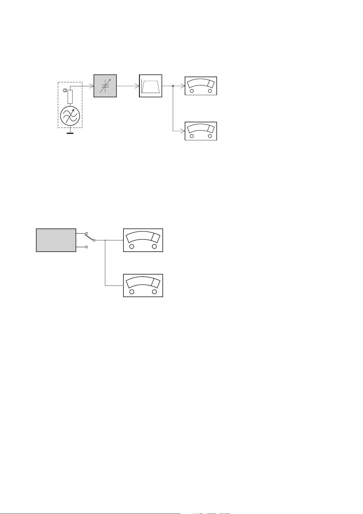
MEASUREMENT SETUP
Tuner FM
1 - 6
Bandpass
LF Voltmeter
e.g. PM2534
RF Generator
e.g. PM5326
DUT
250Hz-15kHz
e.g. 7122 707 48001
Ri=50
S/N and distortion meter
e.g. Sound Technology ST1700B
Use a bandpass filter to eliminate hum (50Hz, 100Hz) and disturbance from the pilottone (19kHz, 38kHz).
CD
Use Audio Signal Disc
(replaces test disc 3)
DUT
SBC429 4822 397 30184
L
R
S/N and distortion meter
e.g. Sound Technology ST1700B
LEVEL METER
e.g. Sennheiser UPM550
with FF-filter
Page 7
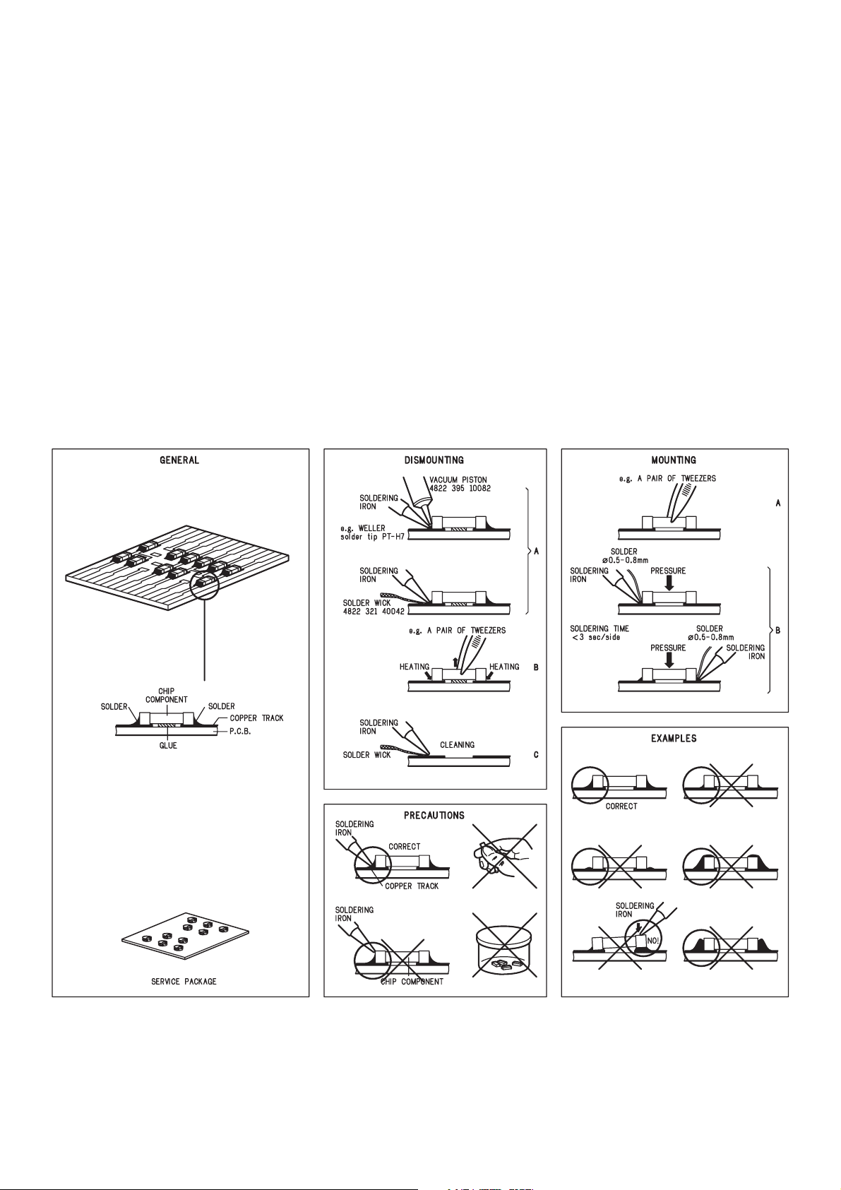
SERVICE AIDS
Service Tools:
Universal Torx driver holder .................................4822 395 91019
Torx bit T10 150mm ...........................................4822 395 50456
Torx driver set T6-T20 .........................................4822 395 50145
Torx driver T10 extended .....................................4822 395 50423
Compact Disc:
SBC426/426A Test disc 5 + 5A ...........................4822 397 30096
SBC442 Audio Burn-in test disc 1kHz .................4822 397 30155
SBC429 Audio Signals disc .................................4822 397 30184
Dolby Pro-logic Test Disc ....................................4822 395 10216
HANDLING CHIP COMPONENTS
1 - 7
Page 8
GB
A
WARNING
1 - 8
ESD
WAARSCHUWING
NL
ll ICs and many other semi-conductors are
susceptible to electrostatic discharges (ESD).
Careless handling during repair can reduce life
drastically.
When repairing, make sure that you are
connected with the same potential as the mass
of the set via a wrist wrap with resistance.
Keep components and tools also at this
potential.
F
ATTENTION
Tous les IC et beaucoup d’autres
semi-conducteurs sont sensibles aux
décharges statiques (ESD).
Leur longévité pourrait être considérablement
écourtée par le fait qu’aucune précaution n’est
prise à leur manipulation.
Lors de réparations, s’assurer de bien être relié
au même potentiel que la masse de l’appareil et
enfiler le bracelet serti d’une résistance de
sécurité.
Veiller à ce que les composants ainsi que les
outils que l’on utilise soient également à ce
potentiel.
GB
Complete Kit ESD3 (small tablemat, wristband,
connection box, estention cable and earth cable ....... 4822 310 10671
Wristband tester ................................................................. 4822 344 13999
D
WARNUNG
Alle ICs und viele andere Halbleiter sind
empfindlich gegenüber elektrostatischen
Entladungen (ESD).
Unsorgfältige Behandlung im Reparaturfall kan
die Lebensdauer drastisch reduzieren.
Veranlassen Sie, dass Sie im Reparaturfall über
ein Pulsarmband mit Widerstand verbunden
sind mit dem gleichen Potential wie die Masse
des Gerätes.
Bauteile und Hilfsmittel auch auf dieses gleiche
Potential halten.
ESD PROTECTION EQUIPMENT
Alle IC’s en vele andere halfgeleiders zijn
gevoelig voor electrostatische ontladingen
(ESD).
Onzorgvuldig behandelen tijdens reparatie kan
de levensduur drastisch doen verminderen.
Zorg ervoor dat u tijdens reparatie via een
polsband met weerstand verbonden bent met
hetzelfde potentiaal als de massa van het
apparaat.
Houd componenten en hulpmiddelen ook op
ditzelfde potentiaal.
I
AVVERTIMENTO
Tutti IC e parecchi semi-conduttori sono
sensibili alle scariche statiche (ESD).
La loro longevità potrebbe essere fortemente
ridatta in caso di non osservazione della più
grande cauzione alla loro manipolazione.
Durante le riparazioni occorre quindi essere
collegato allo stesso potenziale che quello della
massa dell’apparecchio tramite un braccialetto
a resistenza.
Assicurarsi che i componenti e anche gli utensili
con quali si lavora siano anche a questo
potenziale.
GB
Safety regulations require that the set be restored to its original
condition and that parts which are identical with those specified,
be used.
Safety components are marked by the symbol
!
.
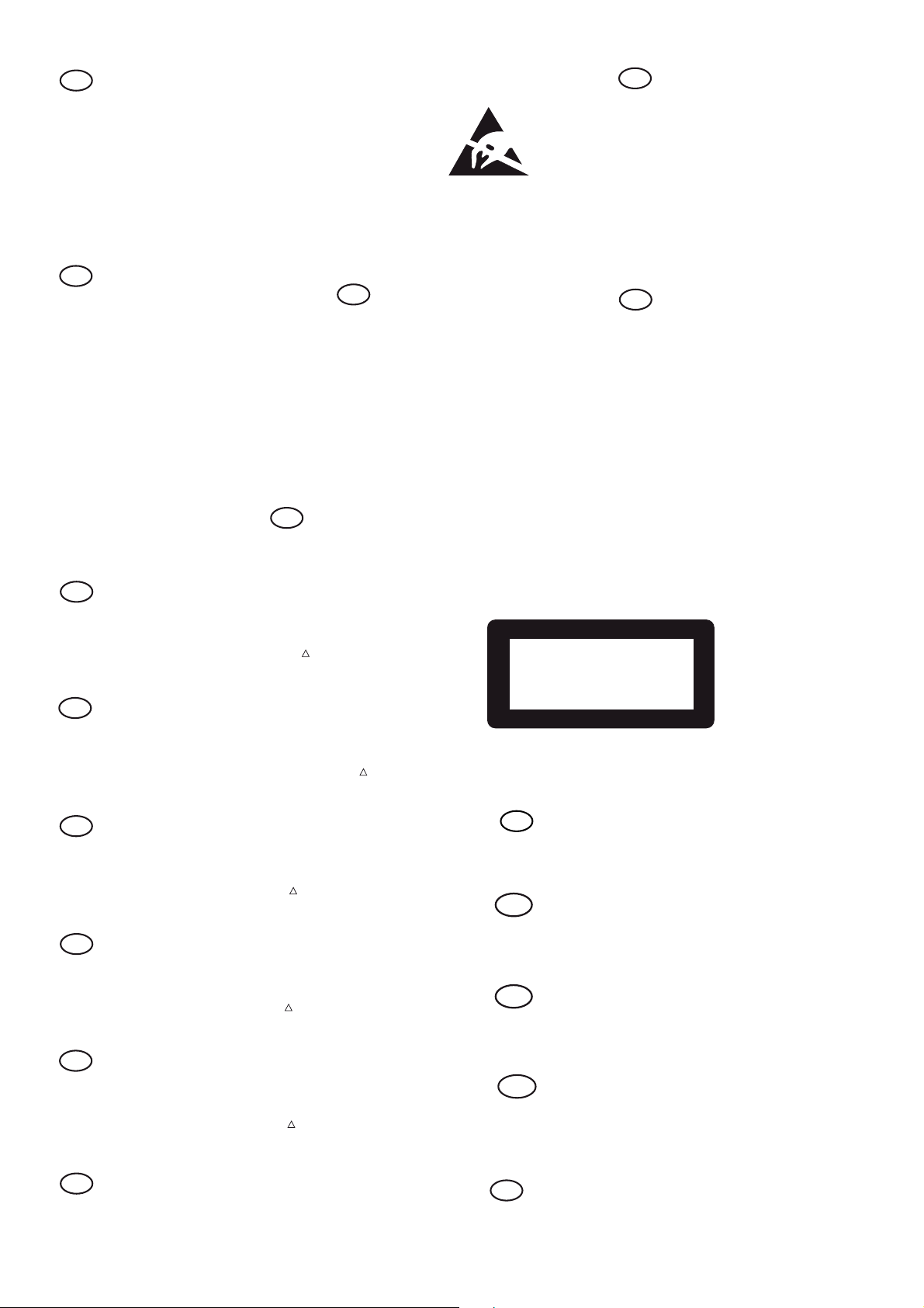
CLASS 1
LASER PRODUCT
NL
Veiligheidsbepalingen vereisen, dat het apparaat bij reparatie in
zijn oorspronkelijke toestand wordt teruggebracht en dat onderdelen,
identiek aan de gespecificeerde, worden toegepast.
De Veiligheidsonderdelen zijn aangeduid met het symbol
!
.
3122 110 03420
F
Les normes de sécurité exigent que l’appareil soit remis à l’état
d’origine et que soient utiliséés les piéces de rechange identiques
à celles spécifiées.
Less composants de sécurité sont marqués
!
.
D
Bei jeder Reparatur sind die geltenden Sicherheitsvorschriften zu
beachten. Der Original zustand des Geräts darf nicht verändert werden;
für Reparaturen sind Original-Ersatzteile zu verwenden.
Sicherheitsbauteile sind durch das Symbol
!
markiert.
I
Le norme di sicurezza esigono che l’apparecchio venga rimesso
nelle condizioni originali e che siano utilizzati i pezzi di ricambio
identici a quelli specificati.
Componenty di sicurezza sono marcati con
!
.
GB
After servicing and before returning set to customer perform a leakage
current measurement test from all exposed metal parts to earth ground
to assure no shock hazard exist, The leakage current must not
exceed 0.5mA.
GB
Warning !
Invisible laser radiation when open.
Avoid direct exposure to beam.
S
Varning !
Osynlig laserstrålning när apparaten är öppnad och spärren
är urkopplad. Betrakta ej strålen.
Varoitus !
SF
Avatussa laitteessa ja suojalukituksen ohitettaessa olet alttiina
näkymättömälle laserisäteilylle. Älä katso säteeseen!
DK Advarse !
Usynlig laserstråling ved åbning når sikkerhedsafbrydere er
ude af funktion. Undgå udsaettelse for stråling.
F
"Pour votre sécurité, ces documents doivent être utilisés par
des spécialistes agréés, seuls habilités à réparer votre
appareil en panne".
Page 9

Pb(Lead) Free Solder
When soldering , be sure to use the pb free solder.
INDENTIFICATION:
Regardless of special logo (not always indicated)
onemust treatall setsfrom 1 Jan 2005 onwards,according
next rules:
Important note: In fact also products of year 2004 must
be treated in this way as long as you avoid mixing solderalloys (leaded/ lead-free). So best to always use SAC305
and the higher temperatures belong to this.
Due to lead-free technology some rules have to be
respected by the workshop during a repair:
• Use only lead-free solder alloy Philips SAC305 with
order code 0622 149 00106. If lead-free solder-paste
is required, please contact the manufacturer of your
solder-equipment. In general use of solder-paste
within workshops should be avoided because paste is
not easy to store and to handle.
• Use only adequate solder tools applicable for lead-
free solder alloy. The solder tool must be able
– To reach at least a solder-temperature of 400@C,
– To stabilize the adjusted temperature at the solder-
tip
– To exchange solder-tips for different applications.
• Adjust your solder tool so that a temperature around
360@C – 380@C is reached and stabilized at the solder
joint. Heating-time of the solder-joint should not exceed
~ 4 sec. Avoid temperatures above 400@C otherwise
wear-out of tips will rise drastically and flux-fluid will
be destroyed. To avoid wear-out of tips switch off unused equipment, or reduce heat.
• Mix of lead-free solder alloy / parts with leaded solder
alloy / parts is possible but PHILIPS recommends
strongly to avoid mixed solder alloy types (leaded and
lead-free).
If one cannot avoid or does not know whether product
is lead-free, clean carefully the solder-joint from old
solder alloy and re-solder with new solder alloy
(SAC305).
• Use only original spare-parts listed in the Service-
Manuals. Not listed standard-material (commodities)
has to be purchased at external companies.
• Special information for BGA-ICs:
– Always use the 12nc-recognizable soldering
temperature profile of the specific BGA (for desoldering always use the lead-free temperature profile,
in case of doubt)
– Lead free BGA-ICs will be delivered in so-called ‘dry-
packaging’ (sealed pack including a silica gel pack) to
protect the IC against moisture. After opening,
1 - 9
dependent of MSL-level seen on indicator-label in the
bag, the BGA-IC possibly still has to be baked dry.
(MSL=Moisture Sensitivity Level). This will be
communicated via AYS-website.
Do not re-use BGAs at all.
• For sets produced before 1.1.2005 (except products
of 2004), containing leaded solder-alloy and
components, all needed spare-parts will be available
till the end of the service-period. For repair of such
sets nothing changes.
• On our website www.atyourservice.ce.Philips.com
you find more information to:
• BGA-de-/soldering (+ baking instructions)
• Heating-profiles of BGAs and other ICs used in
Philips-sets
You will find this and more technical information
within the “magazine”, chapter “workshop news”.
For additional questions please contact your local
repair-helpdesk.
Page 10
2 - 12 - 1
Software upgrade & Procedure to restore product setting
1)Restore factory setting
a) Press “ ” <Home> button on R/C.
b) Select <SETUP>, then press “OK” button on R/C.
c) Select <Advanced>.
d) Select <Restore default settings>,then press <OK> to confirm.
2)Password change
a) Press “
” <Home> button on R/C.
b) Select <SETUP>, then press “OK” button on R/C.
c) Select <preference>.
d) Select <Change Password> <Confirm>, then press <OK> button
on R/C.
“0000” is default password supplied.
3)Trade mode
a) In open model,press “
” <Home> button on R/C.
b) Press “2” “5” “9” on R/C,VFD will display “TRA ON” or “TRA
OFF”.
4)Check software version
a) Press “
” <Home> button on R/C
b) Select <Setup>, then press <OK> button on R/C.
c) Select <Advanced Setup> <Version information>,then press
<OK> button on R/C.
d) TV will show message as follow:
Model:HTB7250D/12
Versions
System SW:X.XX.XXX
Subsystem SW:XX-XX-XX-XX
Wireless(Wi-Fi):XX:XX:XX:XX:XX:XX
Extended unique Identifier(EUI64):0025d1fffeof3c15
PRODUCT ID:A5UDJSCREQVGSCG5
For information,frequently asked questions and
software updates,please visit
www.philips.com/support
Close
e) press <OK> button to exit .
5) Upgrading new software
Method 1: Update software from a USB storage device
a) Create a folder named “UPG” in your USB storage device, and
Copy the latest upgrading software into the folder.
b) Connect the USB storage device to the home theater.
c) Press “
” <Home> button on R/C, and select <Setup>.
d) Select <Advanced> <Software Update> <USB>.
e)Follow the onscreen instructions to confirm the update.
»» Update process takes about 5 minutes to complete.
»» Once complete, the home theater automatically switches off and
restarts.If it does not, disconnect the powercord for a few seconds
and then reconnect it.
Method 2: Update software from the internet
Note: To check for new updates, compare the current software
version of your home theater with the latest software version (if
available) on the Philips web site, and for BD-Live application and
software update, make sure that the network router has access to
the Internet and the firewall is disabled.
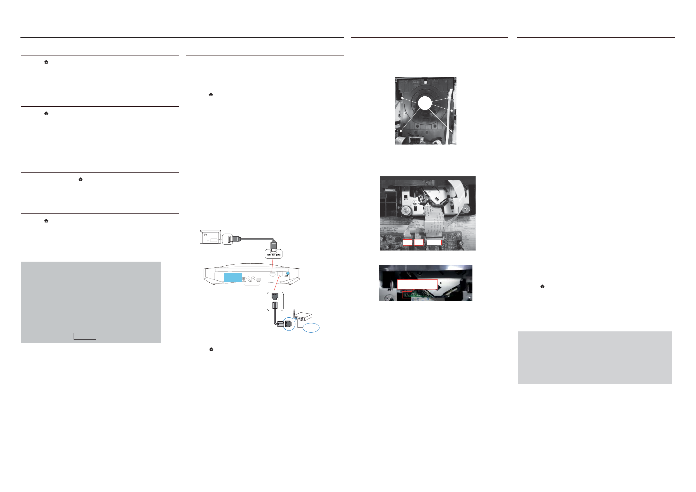
a) The “LAN” jack at the back panel of the set must be connect to
the network router via network cable and the set connect to TV,
Prepare the connection as shown follow:
/NI IMDH
CRA IMDH
b) Press “
” <Home> button on R/C, and select <Setup>.
c) Select <Advanced> <Software Update> <Network>.
»» If an upgrade media is detected, you are prompted to start or
cancel the update.
»» Downloading of the upgrading file maytake long, depending on
your home network condition.
5 Follow the onscreen instructions to confirm the update.
»» Update process takes about 5 minutes to complete.
»» Once complete, the home theater automatically switches off and
restarts.If it does not, disconnect the powercord for a few seconds
and then reconnect it.
LAN
6)How to replace the defective Blu-ray Loader
a) Remove the defective Blu-ray Loader.
b) Remove the shield cover at the top of Blu-ray Loader as shown
7) Update the onscreen help
If the current version of the onscreen help is lower than the latest
version available on www.philips.com/support, download and install
below:
i) Loosen 5 screws on the top of Blu-ray Loader as shown in
figure1
the latest onscreen help.
* A USB flash drive that is FAT or NTFS formatted, with at least
35MB of memory. Do not use a USB hard drive.
* A computer with internet access.
A
* An archive utility that supports the ZIP file format
a) Connect a USB flash drive to your computer.
b) In your web browser, go to www.philips.com/support.
c) At the philips support website, find your product and click on User
Figure 1
c) Assembly Blu-ray Loader to “J800”,”J900”,”J901” on the top of BD
Board as shown below.
manuals, and then locate the User Manual Upgrade Software. (The
help update is available as a zip file).
d) Save the zip file in the root directory of your USB flash drive.
e) Use the archive utility to extract the help update file in the root
directory. (A file named “HTSXXXXeDFU.zip” is extracted under the
UPG folder of your USB flash drive, “xxxx” being the model number
of your home theater.)
f) Disconnect the USB flash drive from your computer.
Caution: Do not switch off the home theater or remove the USB
J900
J901
J800
d) Remove soldered joint on the ESD protection points.
flash dirve during the update.
g) Connect the USB flash drive containing the downloaded file to
your home theater. (Make sure that no disc is loaded inside the disc
compartment)
The ESD Protection points
on the top of board
h) Press “
” <Home> button on R/C.
i) Enter 338 on the remote control.
Bottom side view of OPU
Note: The ESD protection points must be soldered if
www
o the Blu-ray Loader is OK and needs to be disconnected from
connector J800, J900 and J901 of the BD Board.
o the defective Blu-ray Loader is needed to be send back to
supplier for failure analysis and to support backcharging evidence.
j) Follow the onscreen instructions to confirm the update.
k) Disconnect the USB flash drive from the home theater.
CAUTION!
This information is confi dential and may not be
distributed.Only a qualifi ed service person should
reprogram the Region Code.
Page 11
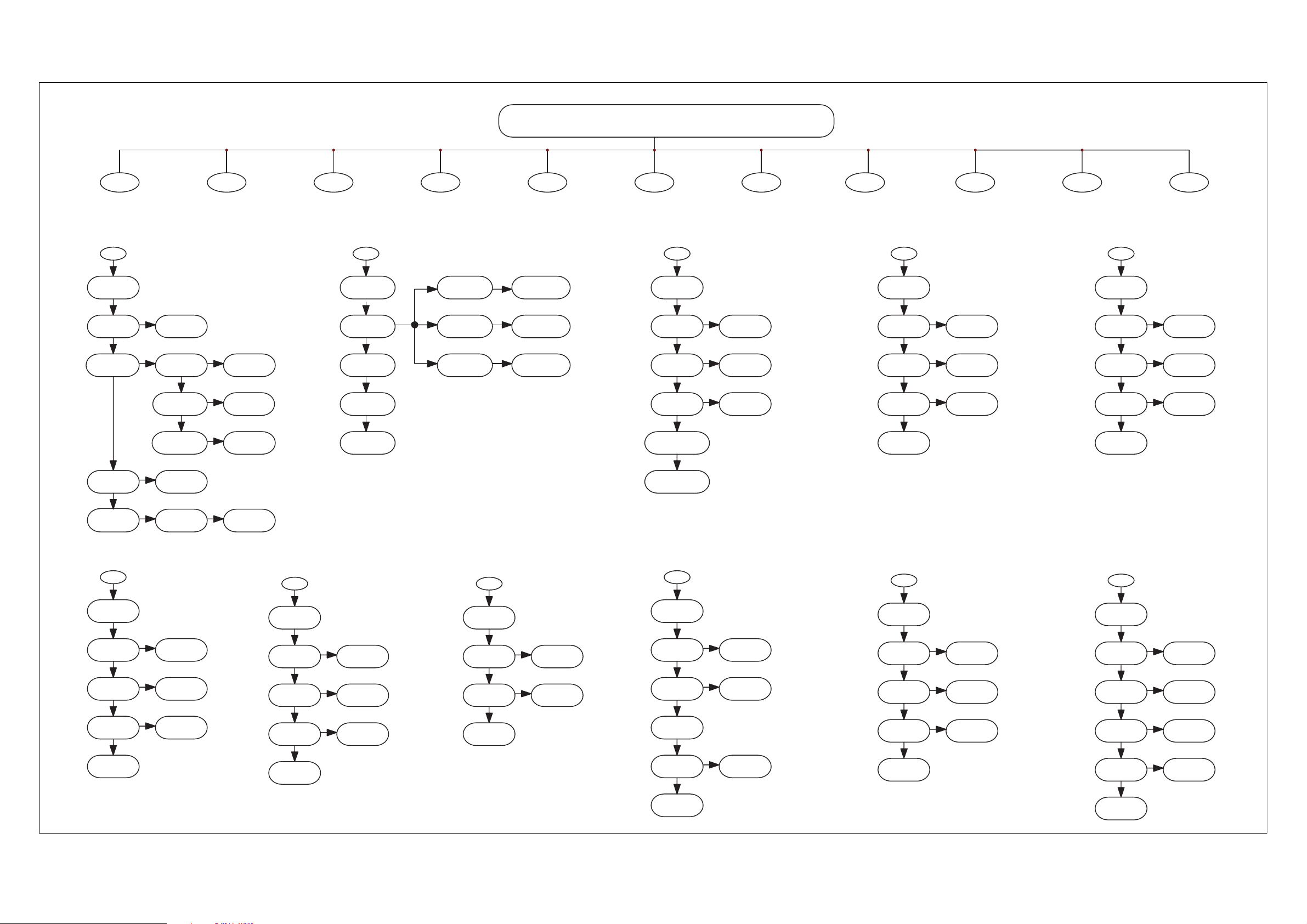
REPAIR INSTRUCTIONS(main unit)
2 - 22 - 2
HTB7225/9225 REPAIR CHART
A
All Functio n
No Working
A
All functi on
No working
Check all system
all cable is loose
or bad INT
NO
Panel stanby LED
show working or Not
WORK
Check All DC TO DC IC
OUT Voltage approx
+5V +12V -12V -24V
CORRECT
Check IC721 IC162
OUT Voltage 3.3V
YES
Re-insert and fix
the cable
NO
Check back power PCB
F901 bad cause damage
Check CN903 JK401
And Its Conjoint parts
Check IC162
And Its Conjoint parts
NO
Check repair
And Its Conjoint parts
YES YES
Check IC101 Pin12 pin13
OSC frequency 8MHz
OK
YES
BAD
NO
OK
B
Power Supply
No Working
Change F901
Check 3m cable
REPAIR ok
Check repair t ouch
PCB Standby circuit
Repair main pcb between
IC201 Q202
And Its Conjoint parts
C
All Functio n
No Sound
Check Repair IC901 IC903
Q901 IC904 D921 And Its
D
Key board
No Functi on
E
VFD bo ard
No Funct ion
No Sound
B C
Power Supply
No working
All Voltage
No Output
YES
Check F901
Bad Cause Damage
No
Check BKVCC
Working or Not
No
CONN CIRCUIT
+32V Voltage
No Output
No
+14V Voltage
No Output
BKVCC Voltage
No Output
Check Q902 Q903 IC905
D923 And Its Conjoint Part
Check D921 Q901
And Its Conjoint Part
Check R919 D921 Q904
And Its Conjoint Part
F
AUX IN
All Functi on
No Sound
Check POWER IC
Voltage +18V ~ +33V
Check Power Ic
Pin 1,2,22
Voltage 12V
Check IC 4103 Pin9/14
Pin35/50 Voltage +3.3v
Check CN201 Pin
And Its Conjoint Part
Check BD Board
See C onte nts BD Boar d
G
MP3 In
No Sound
H
BT In
No Sound
D
Key board
No Function
I
Optica l In
No Sound
J
Tuner No Sound
E
VFD board
No Function
K
Subwoofer No Sound
Yes
No
See C onte nts B
Check the cable connect
CN207 CN600 loose or bad INT
OK
YES
Check IC131
And Its Conjoint Part
OK
No
Check IC721 FB721
And Its Conjoint Par t
Check IC1 Pin12
Voltage approx +3.3 V
Check I C1 Pin7(DAT)
Check IC1 Pin6(CL K)
OK
Check IC1
And Their Conjoint Parts
YES
Re-insert and f ix
the cable
Check the cable connect
CN207 CN600 loose or bad INT
OK
No
And Its Conjoint parts
Check R125
Check IC600 Pin14/33/45
Voltage approx +5V
Check IC600 Pin34
Voltage approx -24 V
OK
No
Check CN601.CN1 And
Their Conjoint Parts
Check IC600 Pin6( DAT)
Check IC600 Pin8(CLK)
Check IC600 Pin9(CE)
OK
Check DP600
And Their Conjoint Parts
YES
Re-insert and f ix
the cable
OK
No
Check IC600
And Its Conjoint part s
OK
No
Check R604/603/602
And Their Conjoint Parts
OK
Yes
F
AUX IN
No Output
Check JK301
INT or No
OK
Check IC304 Pin5/14/36
approx +5V Pin46 approx
+3.3V Yes or No
Yes
Check CN201
Loose or bad INT
OK
Check BD Board
See Contents BD Board
INT
No
Check R312 R313 R377
And Its Conjoint Parts
Yes
Re-insert and fix
Change this jk
the cable
G
MP3 In
No Sound
Check JK831 CN805
RB303 INT or No
OK
Check IC304 Pin5/14/36
approx +5V Pin46 approx
+3.3V Yes or No
Yes
Check CN201
Loose or bad INT
OK
Check BD Board
See Contents BD Board
INT
Change this jk
Check R312 R313 R377
And Its Conjoint Parts
Yes
Re-insert and f ix
the cable
H
BT In
No Sound
Check CN881 CN883
RB303 INT or No
OK
Check BT881 Pin18
+3.3V Yes or No
Yes
Check BT881 Q881 Q882
And Its Conjoint Part
INT
OP
And Its Conjoint Parts
Change this jk
Check L300
I
Optical
No Sound
Check JK303
INT OR NO
OK
Check JK303 pin1
Yes or No
approx +3.3V
OK
Check IC305Pin11/12
f=24.576MHz
OK
Check IC305 Pin3 /19/22
approx +3.3V
OK
Check BD Board
See C onte nts BD Boar d
INT
No
Check And Repair
No
Check R314 R358 R375
REPAIR ok
R343
J
Tuner No Sound
Output
Check Check TUNER PACK
Pin5 approx +3.3V
Yes
Check IC304 Pin5/14/36
approx +5V Pin46 approx
+3.3V Yes or No
Yes
Check CN201
Loose or bad INT
OK
Check BD Board
See C onte nts BD Boar d
No
Check CN3 CN301
And Its Conjoint Par ts
No
Check R312 R313 R377
And Its Conjoint Parts
Yes
Re-insert and f ix
the cable
K
Subwoofer
No Sound
Yes
Check POWER IC
Voltage +18V ~ +33V
OK
Check Power Ic
Pin 1,21,22,23,44
Voltage 12V
OK
Check IC 5202 Pin9/14
Approx Voltage +3.6v
OK
Check CN903 JK401
And Its Conjoint Part
Yes
Check IC4013
See C onte nts C
No
YES
No
INT
Check CN904 RB5201
INT or No
Check R5226
And Its Conjoint Par t
Check IC721 ZD5201
And Its Conjoint Par t
REPAIR ok
Page 12
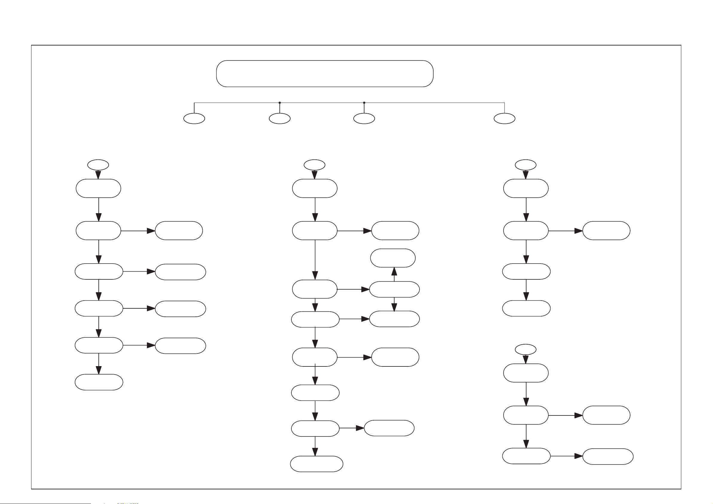
REPAIR INSTRUCTIONS(BD Board)
2 - 32 - 3
A
BD function
No working
Check CN4 cable is loose
or bad INT
YES
BD Function
No Working
Re-insert and fix
the cable
A
BD Board
B
Loading
No DISC
Check Y300 crystal
27MHz Freq Yes or NO
REPAIR CHART
C
All Video
No OUTPUT
B
Loading
No Disc
NO
supersession 27MHz crystal
D
HDMI_RX no output
All Video
No OUTPUT
Check JK805 is
loose or bad
C
loose
Re-insert and fix
the JACK
NO
Check 1.1V 1.5V
Yes or No output
YES
Check 3.3V
Yes or No output
YES
Check Y300 Crystal 27MHz
Yes or No output
YES
Check U100 U201 U101
U102 and connect part
NO
NO
NO
Repair BD pcb between
L1 U1 L3 U905 circuit
Repair BD pcb between
U901 L2 FB19 circuit
Repair BD pcb between
Y300 U100 Circuit
YES
Check Open/Close
Working or Not
OK
Check J800 to
BD loader Cable Loose
ps!Cbe!JOU
OK
Check BD Loader run
Yes or NO
YES
Check U101 U102 U201
and connect part
OK
Determine Picture Output
Zft!ps!Op
OK
Check U10 u408
Boe!Uifjs!Dpokpjou!Qbsut
YES
NO
No
No
Check U10
And Its conjoint parts
No
Check J900 J901
up!CE!Mpbefs!Dbcmf!mpptf
ps!Cbe!JOU
Zft
Re-Insert and fix
the cable
supersession Loader
Check U100 And
Their Conjoint Parts
Bad
supersession JACK
PL
Check JK805
between U100
D
Ethernet No starting
Check P401 loose
or bad INT
NO
Check P401 between U100
YES
INT
supersession P401
Repair P401 between U100
Page 13

3 - 1 3 - 1
DISASSEMBLY INSTRUCTIONS-MAIN UNIT
Note:In some service positions the components or copper patterns of one board may risk touching its
neighbouring pc boards or metallic parts. To prevent such short-circuit use a piece of hard paper or
other insulating material between them.
Dismantling of the VFD Board
1) Loosen 1 screws “D” on the top of VFD Board as shown in gure 4.
Dismantling of the Top Cover
1) Loosen 1 screw “A” at the back panel to remove the top cover as shown in gure 1.
A
Figure 1
Dismantling of the BT Board
1) Loosen 2 screws “B” on the top of BT board as shown in gure 2.
D
Figure 4
Dismantling of the DVD Module
1) Loosen 5 screws “E” at the DVD Module as shown in gure 5.
E
B
Figure 2
Dismantling of the TOUCH Board
1) Loosen 3 screws “C” at the bracket of Touch Board as shown in gure.
C
Figure 5
Dismantling of the MP3 &USB &SENSOR Board
1) Loosen 3 screws “F” on the top of MP3&USB Board as shown in gure 6.
2) Loosen 2 screws “G” on the top of SENSOR Board as shown in gure 7.
G
F
Figure 3
Figure 7
Figure 6
Page 14

Dismantling of the BD Board
1) Loosen 4 screws “H” on the top of BD Board as shown in gure 8.
2) Loosen 1screw “I” at the back panel as shown in gure 9.
H
Figure 8
3 - 2 3 - 2
K
Figure 11
SERVICE POSITIONS (MAIN UNIT)
Service Position A - MAIN&BD Board
Figure 9
Dismantling of the MAIN Board
1) Loosen 6 screws “J” on the top of main board as shown in gure 10.
2) Loosen 2 screws “K” at the back panel as shown in gure 11
J
I
Service Position E - All Boards
Figure 10
Page 15

3 - 3 3 - 3
DISASSEMBLY INSTRUCTIONS-SUBWOOFER
Dismantling of the Subwoofer Rear Panel
1) Loosen 9 screws “Q” at the subwoofer rear panel as shown in gure 17.
Q
Dismantling of the Subwoofer AMP Board
1) Loosen 4 screws “S” on the top of subwoofer AMP board as shown in gure 19.
S
Figure 19
Figure 17
Dismantling of the Power Board
1) Loosen 5 screws “R” on the top of power board as shown in gure 18.
SERVICE POSITIONS (SUBWOOFER)
R
Figure 18
Page 16

3 - 1 3 - 1
DISASSEMBLY INSTRUCTIONS-MAIN UNIT
Note:In some service positions the components or copper patterns of one board may risk touching its
neighbouring pc boards or metallic parts. To prevent such short-circuit use a piece of hard paper or
other insulating material between them.
Dismantling of the VFD Board
1) Loosen 1 screws “D” on the top of VFD Board as shown in gure 4.
Dismantling of the Top Cover
1) Loosen 1 screw “A” at the back panel to remove the top cover as shown in gure 1.
A
Figure 1
Dismantling of the BT Board
1) Loosen 2 screws “B” on the top of BT board as shown in gure 2.
D
Figure 4
Dismantling of the DVD Module
1) Loosen 5 screws “E” at the DVD Module as shown in gure 5.
E
B
Figure 2
Dismantling of the TOUCH Board
1) Loosen 3 screws “C” at the bracket of Touch Board as shown in gure.
C
Figure 5
Dismantling of the MP3 &USB &SENSOR Board
1) Loosen 3 screws “F” on the top of MP3&USB Board as shown in gure 6.
2) Loosen 2 screws “G” on the top of SENSOR Board as shown in gure 7.
G
F
Figure 3
Figure 7
Figure 6
Page 17

Dismantling of the BD Board
1) Loosen 4 screws “H” on the top of BD Board as shown in gure 8.
2) Loosen 1screw “I” at the back panel as shown in gure 9.
H
Figure 8
3 - 2 3 - 2
K
Figure 11
SERVICE POSITIONS (MAIN UNIT)
Service Position A - MAIN&BD Board
Figure 9
Dismantling of the MAIN Board
1) Loosen 6 screws “J” on the top of main board as shown in gure 10.
2) Loosen 2 screws “K” at the back panel as shown in gure 11
J
I
Service Position E - All Boards
Figure 10
Page 18

3 - 3 3 - 3
DISASSEMBLY INSTRUCTIONS-SUBWOOFER
Dismantling of the Subwoofer Rear Panel
1) Loosen 9 screws “Q” at the subwoofer rear panel as shown in gure 17.
Q
Dismantling of the Subwoofer AMP Board
1) Loosen 4 screws “S” on the top of subwoofer AMP board as shown in gure 19.
S
Figure 19
Figure 17
Dismantling of the Power Board
1) Loosen 5 screws “R” on the top of power board as shown in gure 18.
SERVICE POSITIONS (SUBWOOFER)
R
Figure 18
Page 19

BLOCK DIAGRAM
4 - 1 4 - 1
BD OPU Sanyo TRV-415H09
Walleywood loader Loader
RJ-45
Ethernet
BRAND: ALPHA
WiFi Module
Model Number: WUS-N18M
(Ralink RT3370)
USB 2.0
Audio/Karaoke DAO
slot Loader
TPIC2050
Motor driver
Build in(integrated)
USB cable
+5V/1.0A
+5V/1.0A
USB1 Front
RF
Connector
USB2
Current pr otect
TPS2553
Current protect
TPS2553
Audio/Karaoke DAO
CEC
HDMI
HDMI IN + MPEG BOARD
SERVO
BD HDMI1
EP94M3 CTL I2C
DDR3
128MB 2pcs
DDR3
256MB 1pcs
NADN Flash
256MB
BD Backend
MT8580BDAG
H_I2S
BD-MCLK
BD I2S
SPF-MCLK
I2C
Audio I2S
MCLK
IR
INT
I2C
UART
HDMI Out
Write
EDID AT24C02
Serial EEP ROM
Read
iPOD
Implementation
MFI337S3959
ESD Protect
x 2pcs
BK5V
BK5V
+12V
+5V
CEM8311/AO4813
(7.0A MOSFET SW IC)
HDMI1 Out
LDO Reg.
LM1117-33
LDO Reg.
LM1117-33
H/L Power SW control
DC TO DC
TPS54418RE
DC TO DC
G5627F11U
WB1542
DC/DC
LM1117-3.3V
LDO
HD1V8
HD3V3
Motor driver
+12V (1.3A)
+5V
Motor driv er
1.2V
(3.5A)
1.5V
(2.0A)
USB/WiFI
3.3V(1.0A)
3.3V(0.3A)
UART
LM1117-ADJ
LM1117-1.2V
LM1117-1.8V
Debug1
Debug2
Debug3
Debug4
Debug5
GND
+3.3V
For MCU Debug
+3.3V
TX
RX
SW-Upgrade
LDO
LDO
LDO
CEC
9V
TO OPU
1.2V
(0.3A)
1.8V
To video ADC
0R Jump
(Simple)
Powre down
0R Jump
(Advance)
PWR/STBY
UART1
AT24C02
EEPROM
UART2
DE-PWR
EP94M3 CTL I2C
IR
IR
Transistor
PWM port
8 - Char Only THB72XX
LCD Display Only THB9245
13-Char Only THB92XX
AC(to VFD)
VFD DRIVER
STM32F100VC
256K FLASH,16K SRAM
UI-User Input ( Key/IR)
VFD display
D-AMP control
CEC Player
CEC Audio System
Tuner/RDS control
VFD Display
PT6311
7 KEY
LED x 1 only STB for HTB72XX
LED x 7 for HTB92XX
Touch PAD IC
eKT4701
I2C
Tuner Pack
MP3/Mic Delect
DC port
Diode
and R.C
PWM pin
Transistor
FAN Control
CTL IO BT
Display Unit Part
White LED
Only THB92XX
Tuner Audio
From spk output
Fan
HDMI3 IN
EDID AT24C02
Serial EEP ROM
EDID AT24C02
Serial EEP ROM
For HTB72xx
MAIN BOARD
COAXIAL
OPTICAL
Blutooth module
BM84
Audio/Karaoke DAO
Tuner Audio
AUX-IN
MP3/Mic Detect
MP3/Mic
ESD Protect
For HTB92xx
CTL IO BT
BT Audio
AUX in
IC 4558
MP3 in
x 2pcs
MIC in
I2C
CS8422
SPDIF Rx
CS5346
MUX+ADC
Switch
EP94M3
HDMI SPDIF IN(ARC)
BD-MCLK
SPF-MCLK
I2C
SCLK
LRCK
MCLK
3.3V
LDO Reg.
LM1117-33
5V
LDO Reg.
LM1117-33
Mic Mono Jack
Provision Mic for 93/98 version
BD-MCLK
I2C
Mic
SPF-MCLK
BD I2S
1.8V
3.3V
I2C
Audio I2S
H_I2S
MCLK
+32.5V
GND
+15V
GND
BK9V
Reset
S-PWM
S-GND
DE-PWR
STBY
3M 14pin cable
10pin connector
HDMI SPDIF IN(ARC)
H-I2S
+32.5V
(wire #24)
+32.5V
(wire #24)
GND
(wire #24)
GND
(wire #24)
+15V
(wire #24)
+15V
(wire #24)
GND
(wire #24)
GND
(wire #24)
(wire #24)
BK9V
Reset
(wire #28)
S-PWM
(wire #28)
S-GND
(wire #28)
(wire #28)
DE-PWR
(wire #28)
STBY
I2C
PWM IN
+15V
Transistor
MCLK
Buffer
74HC04
+12V
Subwoofer Unit Part
TAS5538
D-AMP PWM
TAS5612
AMP
Fan
VOLUME
FAN CTRL
SUB SPK
180W(10%)
230W(30%)
I2C
TAS5612A
PWR AMP
+-
EP94M3 I2C
DDCTX-I2C
EP94M3-RST
TXHPD To MT8580 HDMI IN
DDCTX-I2C To MT8580 HDMI IN
SRR/SRL
RR/RL
FL
FL
FR/FL
135W
OUTPUT 30% 270W
C/SUB
RR/RL
5
FR/FL
SPK (ohm)
3
SUB
RX5V(H1/2/3)
TO-EP94M3
Subwoofer PSU
Power consumption < 0.5W
PSU
EP94M3-INT
RXHPD(H1/2/3)
STBY
DE-PWR
+33V
+33V
+12V
+12V
BK5V
For HTB92xx
For HTB72xx
Page 20

WIRING DIAGRAM
4 - 2 4 - 2
AC SOCKET
CN901
SV1
SV2
V2
V10
V5
V3
V4
V1
Page 21

5 - 1 5 - 1
IC304 INTERNAL IC DIAGRAM - CS5346 CQZ
MAIN+VFD+SUB+USB+MP3+SENSOR+BT BOARD
TABLE OF CONTENTS
Internal IC Diagram ...........................................................................5-1
Circuit Diagram .................................................................................. 5-3
PCB Layout Top View ........................................................................ 5-4
PCB Layout Bottom View ................................................................... 5-5
3.3 V 5 V
Internal Voltage
Reference
Low-Latency
Anti-Alias Filter
Low-Latency
Anti-Alias Filter
Multibit
Oversampling
ADC
Multibit
Oversampling
ADC
PGA
PGA
®
I²C
™
/SPI
Control Data
Interrupt
Overflow
Reset
Serial
Audio
Output
3.3 V to 5 V
rotalsnarT leveL
rotalsnarT
leveL
ec
a
fretnI
l
a
ir
eS
M
CP
Register Configuration
High Pass
Filter
High Pass
Filter
IC201 INTERNAL IC DIAGRAM - STM32F100VBT6BATR
MUX
+32 dB
+32 dB
Left PGA Output
Right PGA Output
Stereo Input 1
Stereo Input 2
Stereo Input 3
Stereo Input 4 /
Mic Input 1 & 2
Stereo Input 5
Stereo Input 6
Page 22

5 - 2 5 - 2
A
A
IC4103 INTERNAL IC DIAGRAM - TAS5538 DGG
AVSS_PLL
VDD_REF
VRA_PLL
VBGAP
VRD_PLL
DVDD
DVSS
AVD D
AVS S
VDD_PLL
VR_PLL
CM
KL
7
0
auqiB
sd
teD
LP
L
TM
L
F_
TP
LF_LLP
KL
CS
CRL
KL
1NIDS
NIDS
2
DS
3NI
4NIDS
2
I
ADS
LCS
TESER
NDP
M
ETU
LES_PH
E_DNKB
RR
C
reS
lai
lortno
C
I/F
veD
eci
o
C
rtno
l
DAP Control
0
7
teD
auqiB
sd
0
8
8
7
teD
auqiB
sd
0
7
teD
auqiB
sd
0
7
auqiB
teD
sd
0
7
auqiB
teD
sd
0
7
teD
auqiB
sd
0
7
teD
auqiB
sd
8
9
Loud
tfoS
oS
tf
T
eno
oS
tf
T
eno
oS
tf
T
eno
oS
tf
T
eno
tfoS
eno
T
oS
tf
eno
T
oS
tf
T
eno
oS
tf
eno
T
4
e
loV
mu
rtnoC
lo
D
V
V
V
V
V
V
V
V
CR
lo
pmo
C
Loud
tfoS
D
CR
C
lo
pmo
tfoS
Loud
D
CR
lo
C
pmo
tfoS
Loud
C
lo
pmo
Loud
tfoS
C
pmo
lo
Loud
tfoS
C
pmo
lo
Loud
tfoS
C
pmo
lo
tfoS
Loud
C
lo
pmo
8
8
D
CR
RD
C
D
CR
D
CR
RD
C
2
2
D
C
eD
hpmE
kcolB
eD
D
C
hpmE
kcolB
eD
D
C
kcolB
D
C
kcolB
D
C
kcolB
D
C
kcolB
D
C
kcolB
D
C
kcolB
retnI
hpmE
eD
hpmE
eD
etnI
hpmE
eD
E
hpm
eD
hpmE
eD
hpmE
IC305 INTERNAL IC DIAGRAM - CS8422-CNZR QFN
CRS
pretnI
etalo
CRSM
pretnI
etalo
SMWPS
talop
CR
e
SMWPS
CR
talopretnI
e
C
S
R
talopr
e
CRSMWP
pretnI
etalo
CRSMWP
pretnI
etalo
CRSMWP
pretnI
etalo
8
MWPSN
SN
P
W
N
N
N
MWPS
SN
SN
SN
8
CVSP
PA
WP
M
dna
8MA
efoowbuS
r
LA
DI
V
CVSP
Page 23

CIRCUIT DIAGRAM
CN202
FB201
C221
104
C223
104
R291 33
VBSU`UY2`NUL
VBSU`SY2`NUL
R292 33
R293 33
R295 33
R296 33
R297 33
R298 33
R299 33
VTC`N
VTC`N
6
USB606
6
2
2
3
3
4
4
5
5
7
USB2.0
7
C3000
4.7u
Q3002
2SA733
R341 open
INDV`TEB
100
C222
220U/10V
FB202
C224
220U/10V
NJD`TEPVU
CE0JO`ETE3
CE0JO`ETE2
CE0JO`ETE1
CE0JO`TDML
CE0JO`MSDML
CE`NDML
C`NDML
J3D`TEB2` NUL
J3D`DML2`NUL
CE`NVUF
DFD
J3D`JOU` NDV`UP`NUL
CE`JS
SYEBUB1
9533`CDML
NU9691BVEJP!JO!NDML
9533`MSDL
INDV`TDM
IC606
2
J0P2
3
HOE
4
CAB066
HOE
VTC`N
VTC`Q
CE`WDD
Q3001
2SC945
5/8L
R3024
Q3006
2SA733
NJD`TXJUDI2
R3026 1K
Q3007
2SC945
C3018
100U/10V
NQ4!!M0NJD
NQ4!!S
C344 100PC343 102
C342 102
UVO.M
UVO.S
UVOFS`STU
,23/1W
,CE6W
100
CL4/4W
CL4/4W
DFD
TQEJG`JSR
TQEJG`SFTFU
BED`STU
,4/4WE
TQEJG`BSD
J3D`DML2`NUL
J3D`TEB2`NUL
CE`NDML
CE0JO`MSDML
CE0JO`TDML
NJD`TEPVU
9533`HQP4
VTC`Q
7
J0P5
C696
CE`WDD
6
WDD
215
VTC`Q
J0P45J0P3
RB606
5
2
RB4/20
TO BD BOARD
R3003
93L
C3002 150P
R3002
C3001
4.7u
1K
R3001
R3000
3L3
3K3
R3023
2K2
C3017
104
R3025
2K2
600
FB302
600
FB303
R342 open
C345 100P
R308
18K
R309
18K
D306
R303 33K
D307
C3005
IC301A
4
,
4.7u
2
C.
3
JRC4558
.
5
10
R3005
104
100U/16V
D3002
R30043/3L
1N4148
C3003
C3004
,23W
0
R3021
470
R3022
R30191K
Q3004
2SC945
Q3003
2SC945
R3020
270K
47U/16V
C307 475
21L
R346
C308 475
R345
21L
R349 33K
R348 33K
C305 475
BVY.M
C306 475
BVY.S
180P
180P
C312
R304 33K
C313
R373
C301 475
0
C309
open
R310 openR311 open
R374
C302 475
0
C310
open
DDO2361:1.1323
CN201
GPS!!CE!!QDC
NQ4!JO0NJD!JO
BVY!JO
58
57
JK301A
TUNER
CN8/20
RB303
RB4/20
CN301
12
11
10
9
8
7
6
5
UP!CE!CPBSE
4
3
2
1
56
55
54
53
52
51
4:
49
48
47
46
45
44
43
42
J3DJSR
41
3:
39
38
37
36
35
34
33
32
31
2:
29
28
27
26
SY`TEB
25
SY`TDM
24
SY`IQE
23
SY6W`JO3
22
SYIQE`DUM3C
21
SY6W`JO2
:
SYIQE`DUM2C
9
SY6W`JO1
8
SYIQE`DUM1C
7
FQ:5N4`STUC
6
FQ:5N4`JOUC
5
4
3
2
2
NJD`EFUFDU
NQ4!!S
5
NQ4!!M0NJD
AUX-L
AUX-R
2
3
4
5
6
J3D`TEB4 `UVOFS0FQSPN
7
J3D`TD M4`UVOFS0FQSPN
8
9
RCI024004-0005
IC202
2
T1
3
T2
4
T3
5
HOE
R281
R282
R283
R284
UVOFS`STU
CL4/4W
CL4/4W
TO 5538 17PIN
R209
C`NDML
C218 10P
ASW100010-0007
R3006
1
.23W
D3003
1N4148
D3004
1N4148
C3015
C311 180P
XL201
D3005
R203
J3D`JOU`NDV`UP`NUL
JK303A
24C16B
C201
10P
C203
R2034
4.7K
J3D`TDM3`UJ6649
PVU
HOE
WDD
C3014
10U/50V
C314 180P
R204
30K
R2033
4.7K
C3006
WDD
XD
TDM
TEB
4.7K
4.7K
10K
10K
8MHz
C202
10P
1N4148
R2032
4.7K
J3D`TEB3`UJ6649
4
3
2
4.7u
R3007 10K
1N4148
R3018 4K7
BVY`M
BVY`S
UVO`M
UVO`S
9
8
7
R279 33
6
R280 33
UPVDI`QBOFM` SFTFU
100K
104
4.7K
GBO`MFWFM`EFUFU
BNQ`MFWFM`EFUFU
BJSQMBZ.SFTU
CE`MFE
IQ`DPOUSPM
D202
R210
3.3M
C1029
R343 10
C320
104
R3008 4.7K
R3028 3/3L
Q3005
2SC945
NQ4`M
NQ4`S
R278
C214
C215
C216
C217
R2029
4.7K
J3D`TEB6`DT645709533
OPEN
R3009
C3007 270P
R3017
100K
C339
100U
6
7
104
C3008
104
C213
100P
100P
100P
100P
MCU RST
BVEJP44W
,
.
R3016
1K
33
J3D`TDM4`UVOFS0FQSPN
J3D`TEB4`UVOFS0FQSPN
R208
D201 1N4148
R211 2 2K
Q201
KTC3875
R2027
4.7K
UPVDI`QBOFM`SFTFU
R344 10
38L
C,
9
R3010
C3009
100U/16V
R3015
100K
R3014
3k3
5 - 3 5 - 3
DP601
VFD_32P
211Q
D111
SR34
9
8
6
7
C115 562
220U/10V
BD2
C606106
10K
10K
10K
211Q
C854
CN883
CN17/10H
C114 68
L111
6.8UH
R600
2R2
102
C603
C600
C602
100U/10V
104
R605 56K
63
62
PTD
HOE
2
T2
3
T3
4
T4
5
T5
6
EPVU
7
EJO
8
OD
9
DML
:
TUC
21
L2
22
L3
23
L4
24
L5
DEE25TH20LT226TH30LT327TH40LT428TH50LT529TH60LT62:TH70LT731TH80LT832TH90LT933TH:0LT:34TH210LT2135TH2236TH23
,6WE
.38/W
C601 104
NQ4!!M`N
HOE`N2
NQ4!!S` N
NJD`EFU
BVEJP44 W
28
27
C`GM`B
26
25
C`GS`B
24
VBSU6`SY
23
VBSU6`UY
22
21
OFYU
:
QMBZ0QBVTF/
9
QSWF
8
7
1113
6
CU`PO0PG G
5
NVUF`EFU/
4
3
1112
2
C111
C112
C113
104
10UF
220U
R113
510
FB722
600
220U/10V
C722 104
C723
DP600
VFD_45P
1
23456789:
R660
open
R659
open
MFE261MFE35:MFE459MFE558MFE6
6.8V
ZD601
C611
C607
470
22U/50V
22UF/5 0V MIN
RB805
CN4/20
M014
R111
12K
C169
R11512K
R112
2K7
100U/16V
BVEJP44W
C724
104
23456789:
2122232425262728292:3132333435363738393:414243
2122232425262728292:3132333435363738393:4142434445464748494:5154555652
R661 0
R662 0
R663 0
51
57
56
IC600
HS255HS354HS453HS552HS6
WEE
4:
HS7
49
HS8
48
HS9
47
TH310HS:
46
TH2:0HS21
45
.38/W
WFF
,6WE
44
WDD
43
TH290HS22
42
TH280HS23
41
TH270HS24
3:
TH260HS25
39
TH25
38
TH24
IC_PT63 11
37
HOE
C605
102
R618
,23WE
330R
+
C614
10UF/3 5V MIN
SBO119161.2113
+
C613
22UF/3 5V MIN
SBQ119661.1112
Q600
2SC8050
Q602
2SC8550
HOE
VTC0 NQ40 QDC
6
USB701
6
2
2
3
VTCN
3
VTCQ
4
4
5
VTC6W
5
7
USB2.0
7
R617
R616
R615
470R
470R
10K
C612
+
CL4/4W
,23/1W
QXN`QTV`WDD`dpouspm3
,TVC
.TVC
FB400
60
QTV`PO0PGG
EF`QXS
FB401
60
C420
15P
C404
220U/25V
C147
R143
FB145
,24W
80
7
C145
C146
104
100U
R144
CL23W
C160
10U/16V
,CE6W
C110
104
,24W
,24W
22U35V
L145
8
9
2
0.22
3
JT
TD
ED
TF
Wdd
100UH
4
UD
D114
FM140
HOE5DJo
R145
C144
6
100P
56K
3K
AP34063
IC141
JD273
JD.BQ3315
2
JO
4
DF
10K
C167
R165
104
R163
10K
C168
104
FB121
80
IC121
3
WJO
4
FO
5
R124
TT
200K
R137
104
C130
68K
C128
C127
100U
104 change 103
C136
104
FB108
R135
200K
80
104
68K
100U/25V
C140
R136
C138
R620
3.9K
C705
104
C4008 220U/10V
TPS54331
2
3
4
5
C137
104 change103
R631 0
C402
15P
C403
104
D113
FM140
R632 0
3
C124
104
2
CPPU
HOE
WTFO
DPNQ
CPPU
WJO
FO
TT
R633 0
R634 0
R619
330R
HOE
C4007 104
R404
1K
R405
100K
R407 0
R406 0
,44/6W
C407
1uF
C119
104
PVU
BEK
HOE
D121
SR34
9
QI
8
6
7
C126 562
IC131
HOE
DPNQ
WTFO
IC_TPS54331
R636 0
R635 0
SDO119161.2112
,4/4WE
C401
15P
C406
104
.38W
6
5
R166
9K1
L121
6.8UH
C125 68
9
QI
8
7
6
HTB7251D
HTB9225D
45
53
open
R657
102
R601
R658
2R2
open
C604
BD3
R637 0
R638 0
R639 0
R640 0
R641 0
R642 0
R622
33R
C615
105
R621
Q601
2SC8050
1K
RB703
2
6
RB5/20
M007
M013
FB723
600
D206
1N4148
Q401
C408
2SC945
105
WBMJE3
HOE
CL23W
EF`QXS`E
QPXFS`PO0PGG`D
HOE
,24W
R401
3.3
C405
103
D112
FB107
100MHZ
IN4148
C142
104
C141
47U/35V
15K
R167
C165
R168
10U/16V
150K
C121
C122
C123
104
10UF
220U
R122
R123
2K2
510
R116
C132
L131
C133
10UF/10V
6.8UH
10UF/10V
D131
SR34
C134
C135
562
68
R134
510
R648 open
R647 open
R646 open
R645 open
R644 open
R643 open
R653 open
R654 open
R655 open
R656 open
R649 open
R650 open
R651 open
R652 open
CN601
CL4/41W
QXNQXN
,4/4W
C4130 104
C4155 104
C4154 220U/10V
R403
EF`QXS
4k7
R402
2K4
C409
JK401
15P
2
3
4
5
6
7
8
9
:
21
.23W
C143
100U
CL4/4W
C166
104
FB109
80
FB105
R121
100MHZ
12K
C139
104
C199
100U/16V
33
,23/1W
1K
R131
104
100U/16V
R132
20K
C131
C198
R133
1K5
2
U6W
3
4
U`EB
5
U`DML
6
7
CN6/P1.0H
TVCXPPGFS!BNQ
T,23W
C5716
R571310
333
104
55
54
CTU`B
HWEE`B
HWEE`C2PUX3TE6QXN`B7SFTFU`BC8QXN`C9PD`BEK:HOE21BKOE22WSFH23N424N325N226QXN`D27SFTFU`DE28QXN`E29WEE32HWEE`D
TP1
TP504
R5701
C5701
104
10
T,23W
UXFO
R594
10K
D585 1N4148
R597
BNQ`MFWFM`EFUFU
1K
ZD585
R598 47K
C5991 104
RCZ005004-1020
,CE6W
,6W
C5723 102 C5722
X`TVC,
R5715
3.3
103
C5721
C5719
104
C5717 C474/63V
L570210UH/10A
,WDD`B
C5715
53
52
OD
OD4OD
5
R57030
C5745
104
D586
1N4148
C599 47U/25V
,WDD`B
104
C5714
C5713
104
C5712
333
49
45
47
4:
46
51
PVU`C
PVU`B
HOE`C48HOE`B
QWEE`C
QWEE`B
QWEE`B
IC_TAS5342ADDV
R570727K
R57081
R5705
R570433
R5718 33
.TVC
33
R5728
IC5702G
,TVC
10K
WBMJE3`X
74HC04
8
25
21 22
.TVC
IC5702E
IC5702D
74HC04
74HC04
3 2
IC5702A
IC5702F
74HC04
74HC04
7 6
IC5702C
IC5702B
74HC04
74HC04
C597
R591
1K
4.7uF
C598
D587
1N4148
150K
R596
Q,23W
WBMJE2
R595 10K
,GM
.GM
,GS
.GS
CLOE`FSS
Q,23W
D588
1N4148
R5301
C5301 104
C5302 10U/16V
C5303 104
R5302 24K
R5303 33
R5304 33
R5305 33
R5306 33
R5307 33
R5308 33
R5309 OPEN
R5310 33
C5307 104
R5311
4.7uF
C5304 104
C5305 1uF
C5306 1uF
R592
1K
3.3
3.3
C5720 103 R5 714 3 .3
,WDD`B
R5712
C5709
C5708
C5711
333
42
43
CTU`D44CTU`C
QWEE`D
C5702
104
L5703
2.4UH
C5734
104
R5734
open
9
:
23
24
5 4
GM,
GS,
2
HWEE`BC
3
WEE
4
PD!BEK
5
0SFTFU
6
JOQVU`B
7
JOQVU`C
8
D`TUBSU
9
EWEE
:
HOE
21
HOE
22
HOE
23
HOE
24
BWEE
25
JOQVU`D
26
JOQVU`E
27
0GBVMU
28
0PUX
29
0DMJQ
2:
N2
31
N3
32
N4
33
HWEE`DE
TQFBLFS!KBDL
3.3
41
TP503
R5725
100K
A01/HU011075L
C5710
C5707 104
HOE`E3:HOE`D
UBT6263!EJHJUBM!QPXFS
TP
R5729 3K3
C5742
,4/4WE
QXN`GBO`DPOUSPM
IC5301
X`TVC.
103
39
PVU`E
UBT64YY!
C5746
104
C5727
104
104
GBO`MFWFM`EFUFU
CN5701
CN2/396
2
3
X`TVC,
X`TVC.
,23W/
T,23W
,WDD`B
R5711
C5705104
C5706
333
10
36
34
35
37
38
OD
CTU`E
QWEE`E
QWEE`E
HWEE`E
IC5701
OD2:OD
33
31
0
C5703
C5704
R5710
R57091
10
104
R5706
104
T,23WT,23W
,23W`B
R5727
1K5
C5726
ZD5701
4V7
100U/16V
15P
C5741
,TVC`X
R501
10k
CTU`B
CTU`C
HOE
HOE
PVU`B
PVU`B
QWEE`BC
QWEE`BC
QWEE`BC
PVU`C
HOE
HOE
PVU`D
QWEE`DE
QWEE`DE
QWEE`DE
PVU`E
TAS5612LA DIGITAL POWER
PVU`E
HOE
HOE
CTU`D
CTU`E
3K9
R506
R502
1K
55
C5331C333
54
53
52
51
4:
49
48
47
46
45
44
43
42
41
3:
39
38
37
36
35
34
C5308
C5332C
333
R5731
100K
,23W
2SC945
100K
R503
L5303 10UH/10A
C5309333
333
C5743
R5732
R504
560
Q501
10UH/10A
C5321 104
C5320 104
C5319 104
10UH/10A
10UH/10A
104
3K3
R507
10K
D501
1N4148
QWEE
L5304
C5341 104
C5322
470U/50V
R5113
3.3
R5118
3.3
L5302
104
C5310
C5311
470U/50V
L5301
24W
R5226
,WDD`B
T,23W
M021 M023M022
.TVC`X
C5744
15P
Q502 KTC8050
R505
100
C501
10U/50V
C5325
104
C5323
474
C5326
104
C5114
103
C5132
103
C5313
104
C5312
474
C5314
104
Q5201
Q_2SC8050SMT
,23W/
R5227
2K2
C5238100U/25V
C5239
C5241100U/16V
R5228
C5240
C520
0
R5229
104
2R2
C5236
220U/16V
FB5701
100
FB5702
100
R5700
C5724220U/16V
C5725
104
D502
1N4148
C502 104
FB5101
R5315
3.3
C5327
103
C5328
103
R5314
3.3
R5313
3.3
C5315
103
C5316
103
R5312
3.3
FB5102
104
20K
33U/16V
FB5203
100
,WDD`B
Q,23/1W
104
C5237
2R2
C5732
104
C503
220U/16V
100
,WDD
FB5204
100
RB5700
,WDD
3.3
R5717
C5730 104
C5729
Q5702
KTC8050
,23W`B
2
d3f
c
C5736100U/16V
R5721
4
R5722
C5737
R5723
20K
33U/16V
M024
M025 M026
CN2/25
CN501
2
3
2
103
3
C5731
4
1uF
5
WBMJE3`X
6
,TVC`X
7
8
9
.TVC`X
,24W`B
1K5
0
TO PSU
:
RB9/25
C5738
C5739100U/16V
104
.TVC`X.TVC
NC
R5733
,TVC`X,TVC
NC
R5724
GBO2
,44/6W
C5343 104
C5329
102
L5305
GM,
42
GM.
5
3
OPEN
C5330
102
C5317
102
L5306
2
3 5
OPEN
C5318
102
100
,44/6W
GM!TQL!)6*
219!X!)UIE21&*
246X!)UIE41&*
JK5301
TS!TQL!)6
*
219X!)UIE21&*
TQFBLFS!KBDL
246X!)UIE41&*
GS,
4
GS.
102
C5718
104
470U/50V
104
PVU`D
C5342 104
CN203
2
CL4/4W
VBSU6`SY
VBSU6`UY
10K
,4/4WE
CL4/4W
R277 10K
J3D!TDM7!UPVDI
J3D!TEB7!UPVDI
UVOFS`STU
R201
33
R202
33
CL4/4W
R205
33
R206
R207
33
33
0
DFD`JO
DFD`PVU
R202410K
R202510K
R2026
R2023
R2022
R2021
4.7K
4.7K
10K
10K
ETQ`EFCVH
NJD`EFUFDU
NJD`TXJUDI2
J3D`TEB2`NUL
J3D`DML2`NUL
NJD`TX`3
R1084
OPEN
R3011
120
IC301B
8
JRC4558
10
,23W
C3016
100U/16V
C3010
4.7u
,23W
R3012 2.2K
C3012 105
R276 4.7K
R288 4.7K
2
QF3
3
QF4
4
QF5
5
QF6
6
QF7
7
WCBU
8
QD24.UBNQFS.SUD
9
QD25.PTD43`JO
:
QD26.PTD43`PVU
21
WTT`6
22
WEE`6
23
PTD`JO
24
PTD`PVU
25
OSTU
26
QD1
27
QD2
28
QD3
29
QD4
2:
WTTB
31
WSFG.
32
WSFG,
33
WEEB
34
QB1.XLVQ
35
QB2
36
QB3
CL4/4W
R212
4K7
D203
1N4001
D204
1N4148
4K7
R215
4K7
R213
CE`JS
,4/4WE
104
C322
C3011 10U/16V
R3013 7/9L
C3013 105
R273
INDV`TEB
INDV`TDM
QXN`WGE`BD
QXN`GBO`DPOUS PM
QXN`QTV`WDD`dpouspm3
SY`TEB
CL4/4W
R27533
R28633
R274 10K
R272 33
R271 33
CPPU1
::
:4
:9
211
:5
QC9:6QC::7QF1:8QF2
WTT`4
WEE`4
CPPU1
STM32F100VC
RCI321006-0000
QB437WTT`538WEE`539QB53:QB641QB742QB843QD544QD645QC146QC247QC30CPPU2
33
JS
R218 33
R219 33
R220 33
CL4/4W
R216 33
R217 33
R221
TDQ`DML
TDQ`NPTJ
ETQ`JSR
TDQ`NJTP0TEB
NJD`EFUFDU
NJD`TXJUDI2
UP!!5:6424!5Qjo!
UP!5:6424!237Qjo
UP!5:6424!!235Qjo
UP!5:6424!!234Qjo
R1057 open
BVEJP44W
R375
4.7
BVEJP44W
PQUJDBM`T QEJG
TQEJG`BSD
C329 10 4
C1032
103
C328 10 4
C330 104
9533`JOU2
FQ:5N4`STUC
SY`TDM
UP!!DO@!2Qjo!
UP!!DO@!3Qjo!
efcvh5
efcvh6
R268 33
R270 33
98
QE899QC49:QC5:1QC6:2QC7:3QC8
256 K
IC201
QF849QF94:QF:51QF2152QF2253QF2354QF2455QF2556QF2657QC2158QC22
48
10K
10K
33
33
R223
R285
R222
R2044
1112
1113
TL`B
MFE!`TX
TQEJG`SFTFU
6457`STU
9533`HQP4
R319 4K7
R318 4K7
R1095 4K7
DPBYJBM`TQEJG
C337 10U/16V
R3320
BVEJP44W
WE
SYIQE`DUM1C
SYIQE`DUM2C
SYIQE`DUM3C
R266 33
R267 33
33
WGE`DL
WGE`DF
TQEJG`SFTFU
C1036 OPEN
C375 15 P
R3330
R377 4.7
C317 104
6457.TEB
6457.TDM
WMD
R320
6457`STU
BED`STU
NQ4`M
0
NQ4`S
C`GM`B
C`GS`B
BVY`M
BVY`S
WMD
R312 10
,6W
C319 104
R265 33
R22633R22433R225
WGE`EB
9533`CDML
2
3
4
5
6
7
8
9
R334 33
J3D`DML2`NUL
J3D`TDM4`UVOFS0FQSPN
R264 33
R228 33
NDML`TXJUDI
9533`MSDL
C376 15 P
SY10SYQ1
SY20SYO1
WB
BHOE
SY30SYQ2
SY40SYO2
BE10DT
BE20DEJO
R335 33
J3D`TEB2`NUL
C332
2
TEB0DEPVU
3
TDM0DDML
4
BE10DT
5
BE20DEJO
6
WMD
7
STU
8
BJO4B
9
BJO4C
:
BJO3B
21
BJO3C
22
BJO2B
23
BJO2C
,6W
J3D`TEB4` UVOFS0FQSPN
VBSU6`SY
33
33
R26233R263 33
R261
91
QE192QE293QE394QE495QE596QE697QE7
0
R229
R230 33
XJSMFTT`SFTFU
J3D`DML2`NUL
TQEJG`SFTFU
NU9691BVEJP!JO!NDML
R32733
R3570
C377 15 P
43
STU
TDM0DDML:TEB0DEPVU21YUJ22YUP23JMSDL24JTDML25TEJO26HQP1
XL305
24.576MHZ
C3051 15P
10U/16V
10U/16V
C333
C323 104
VBSU6`UY
R25933R260
59
33
R231
J3D`TEB2`NUL
NU9691BVEJP!JO!NDML
9533`HQP4
R328
33
41
42
SNDL
IC305
CS8422
R321 open
CL4/4W
UP!@
UP!@!
C212 104
efcvh3
efcvh4
QB2587QB2688QD2189QD228:QD23
86
WEE`3
85
WTT`3
84
OD
83
QB24
82
QB23
81
QB22
7:
QB21
79
QB:
78
QB9
77
QD:
76
QD9
75
QD8
74
QD7
73
QE26
72
QE25
71
QE24
6:
QE23
69
QE22
68
QE21
67
QE:
66
QE9
65
QC26
64
QC25
63
QC24
62
QC23
WTT`25:WEE`2
61
R232
10k
CL4/4W
9533`MSDL
9533`CDML
SYEBUB1
R32933
R33033
R33133
37
3:
39
HQP4
UEN`JO
TEPVU238PTDML2
PMSDL2
R336 33
R337 33
R338 33
C3052 15P
R322 open
6457.PW
6457.JOU
6457.NDML
56
58
59
55
57
WE
JOU
PWGM
EHOE
IC304
CS5346
BHOE24WB25BGJMUB26BGJMUC27WR28UTUP29GJMU,2:UTUJ31BJO5B0NJDJO232BJO5C0NJDJO333BJO6B34BJO6C
222
C348 222
C347
C334 10U/16V
ETQ`EFCVH
efcvh6
104
104
104
efcvh5
efcvh4
efcvh3
C207 104
C206 104
C211
C210
C208
C209 104
efcvh2
R252
10K
efcvh2
UP@
OFYU
33
R898
QSWF
33
R897
VBSU`SY2`NUL
R249 3 3
VBSU`UY2`NUL
33
R248
J3D`JOU`NDV`UP`NUL
R247 33
SY`IQE
R246 3 3
FQ:5N4`JOUC
33
R245
QMBZ0QBVTF/
33
R896
CU`PO0PG G
33
R895
SY6W`JO3
R244 3 3
SY6W`JO2
R243 33
SY6W`JO1
R287 33
NVUF`EFU/
R241 33
UJ6649`SFTFU
R240 33
R239 33
J3D`TDM3`UJ6649
R238
J3D`TEB3`UJ6649
33
1K
R233
CL4/4W QTV`PO0PGG
Q202
QXN`QPXFS
2SC945
R361
10k
C219
104
QXN`QTV`WDD `dpouspm3
BVEJP44W
C353 100U/10V
R358 4.7
104
C326
36
10U/16V
C335
C1035
PMSDL3
35
PTDML3
103
34
TEPVU3
33
WM
32
EHOE
31
WE`GJMU
R314 4.7
2:
W`SFH
0
29
HPQ3
28
HQP2
R340 33
44
HOE
R359 OPEN
27
103
C327 10 4
C331 10 4
C338 10U/16V
C1034 103
C1033
6457.TDM
R317 33
6457.TEB
R316 33
R323 0
R324 33
R325 33
6457.TDML
6457.TEPVU
R326
33
6457.MSDL
54
52
53
48
51
OD49OD4:OD
UTUJ
TDML
MSDL
NDML
TEPVU
WMT
UTUP
BHOE
BHOE
QHBPVUC
QHBPVUB
BJO7C
BJO7B
NJDCJBT
35
47U/16V
C324 10 4
C349
C325 104
UVO`M
UVO`S
LBSBPLF`M
LBSBPLF`S
5
CN4/20
2
3
C204
104
R242 47K
D205
4K7
R2038
WGE`DF
CN204
2
33
3
33
4
5
CN205
6
7
33
8
CN7/20
CL4/4W
C205
47U/10V
NVUF
NVUF
FM140-M
UJ6649`SFTFU
J3D`TDM3`UJ6649
J3D`TEB3`UJ6649
,4/4WE
10K
10K
10K
10K
R2040
R2043
R2039
R2045
VBSU6`UY
VBSU6`SY
VBSU`SY2`NUL
VBSU`UY2`NUL
R258 33
R257
R256
R255 33
R254 33
R253
Q`NVUF
RCD100140-0020
4K7
4K7
R2037
R2036
UJ6649`SFTFU
WGE`EB
WGE`DL
C354 104
WM
BVEJP44W
HOE
R339
TQEJG`JSR
C336 10U/16V
J3D`DML2`NUL
J3D`TEB2`NUL
FB207
CE`NDML
600
CE0JO`MSDML
CE0JO`TDML
NJD`TEPVU
R313
10
47
46
45
OD
44
OD
43
42
41
WB
3:
39
38
37
36
,6W
C352
C318
220U/10V
104
C351 1 04
C350
10uF/10V
UTE1!!GM0GS!!!!PVU!2!!3
UTE3!!D0TVC!!!!PVU!!8!!9
0
CL4/4W
R2012
NC
R2013
NC
Q2002
NC
R2014
NC
CL4/4W
MFE!`TX
PART
FB2009
FB2010
FB211
FB2012
FB2013
FB2014
FB2015
FB2016
D4171 1N4148
,6W
R4171 1K
R4172 22K
C4172 104
,4/4W
R4145
470
C4131
104
C4148 473
,4/4W
UJ6649`SFTFU
CE`NDML
,4/4W
QEO
NVUF
,4/4W
,4/4W
,4/4W
,4/4W
J3D`TEB3`UJ6649
J3D`TDM3 `UJ6649
CE0JO`MSDML
CE0JO`TDML
CE0JO`ETE1
CE0JO`ETE3
M006 M0 09 M012
M005
R2011
Q2001
NC
UC4/4W
C2014
104
NC
C2015
NC
C2016
,23/1W
C727
220U/16V
,6W
R2006
10K
R2007
10K
QXN`WGE`BD
MDE`JSR
FB2010
HOE
FB2011
MDE`SE
FB2012
.38W
FB2013
,23W
FB2014
,4/4WE
FB2015
HOE
FB2016
VFD LCD
Yes
No
Yes
No
No
Yes
No
Yes
Yes
No
Yes
No
Yes
No
Yes
No
4W4
L300 21VI C887
100U/16V
C4171
,5/7W
Q4171 2SA733
R4173 4K7
R4146
470
472
472
C4149
C4159
C4158 473
R4102 4K7
R4104 33
R4128
R4107 4K7
R4109 4K7
R4110 4K7
R4111 OD
R4112 4K7
R4113 33
R4114 33
R4115 33
R4116 33
R4120 33
R4119 33
M008
R2005
33
R4123 100K
R721
104
C728
,4/4WE
R4174 100K
R4142 0
1
C729
220U/16V
Q205
2SC945
1K
Q206
2SC945
600
600
600
600
600
600
600
600
R2003 4K7
R2004 4K7
,5/7W
Q4172 2SC945
C4108 472
C4107
R4132 NC
R4131 NC
C4123 15P
M011
CL4/4W
,6W
Q,23W
104
C730
U6/1W
LCD_DA1
LCD_WR
LCD_CS
C`GS
C`GM
R4103
2.2
,4/4W
R4105
100U/10V
C4129 15P
C4110 104
C4124 15P
JS
FB2018
600
Q3008
2SA733
R2015
1k
,6W
,23W
104
C4003
C4004
220U/10V
CL4/4W
R2002
10K
FB2001 600
UC4/4W
U6/1W
FB2002
2
J3D!TEB7!UPVDI
1
FB2003 33
J3D!TDM7!UPVDI
FB2004 33
WGE`EB
42
FB2005 600FB2009
WGE`DL
41
FB2006 600
WGE`DF
40
FB2007 600
,6W
FB2008 600
MDE`JSR
MDE`SE
Cmvfuppui!!QDC
586
R882
C881
R883
C882
586
FB881
C883
711
21V
C884
C885
215
21V
C886
21V
215
R4176
,44/6W
10K
R4175
1K5
R4106
2.2
C4113 100U/10V
C4112 472
4K7
R4143 0
R4144 18K
4.7U/50V
C4111
C4141 104
C4117 15P
C4118 15P
C4119 15P
C4120 15P
M015
FB2017
600
3K3
R2041
C2012
47U/10V
R2042
3k3
FB4004
100MHZ
R2001
10K
C2001 104
C2002 104
C2003 27P
C2004 27P
600
C2008 27P
C2007 27P
C2006 27P
C2005 27P
C2009 27P
C2010 27P
C2011 27P
2
BPIQN
3
Q41
4
Q31
5
Q11
6
Q15
2L
7
TQLS
8
2L
TQLM
9
WEEB
:
BHOE
21
NJDJ`Q
22
NJD2`O
23
NJD`CJBT
24
BJS
25
BJM
26
STU
27
WEE`JP
28
BEBQ`JO
29
CBU`JO
BM84_PK
R894
4W4
OD
,4/4W
R4181
4K7
NVUF
Q4181
2SC945
IC4103 IC_TAS5538
2
QXN`IQN`M
3
QXN`IQQ`M
4
QXN`IQN`S
5
QXN`IQQ`S
6
BWTT
7
QMM`GMUN
8
QMM`GMUQ
9
WS`BOB
:
BWEE
21
BTFM`WBDT3
22
NDML
23
PTD`SFT
24
EWTT3`DPSF
25
EWEE3`DPSF
26
WBDT2
27
SFTFU
28
IQ`TFM
29
QEO
2:
NVUF
31
TEB
32
TDM
33
MSDML
34
TDML
35
TEJO2
36
TEJO3
37
TEJO4
38
TEJO5
39
WS`EJH
C4142
10U/16V
C2013
104
,23/1W
C4181
5
4
3
2
28
27
26
25
24
23
22
21
:
9
8
7
6
5
4
3
2
IDJ`SYE
IDJ`UYE
TZT`QXS
PO0PGG
BT ON/OFF
104
CN206
Remote
CN4/20
CN207
CN17/10H
CL`PVU
TL20Q14
EWTT2`DPSF
EWEE2`DPSF
HOE
CL4/4W
U.EB
U.DML
HOE
W.EBUB
QXN
W.DML
W.DF
HOE
,6WE
HOE
.38W
,23WE
HOE
HOE
BT881
47
CU`SG
46
HOE
45
Q12
44
Q27
43
42
41
Q16
3:
Q38
39
Q13
38
Q33
37
Q35
36
MFE3
35
MFE2
34
NGC
33
HOE
32
31
2:
R4183
10K
R4184
100K
QXN`Q`7
QXN`N`7
QXN`Q`6
QXN`N`6
WS`QXN
BWTT`QXN
BWEE`QXN
QXN`Q`9
QXN`N`9
QXN`Q`8
QXN`N`8
QXN`Q`5
QXN`N`5
QXN`Q`4
QXN`N`4
QXN`Q`3
QXN`N`3
QXN`Q`2
QXN`N`2
WBMJE
CLOE`FSS
QTWD
UFTU
MSDMLP
TDMLP
TEPVU
RB705
JS`T
5
C703
47P
2
CL4/4W`T
RB4/20
LD701
LED_D3MM
CN600
28
CL4/41W
27
U6W
U6W
26
U`EB
25
U`DML
24
23
W.EBUB
22
QXN
21
W.DML
:
W.DF
9
8
,6WE
7
6
5
4
3
2
CN17/1.0
JK831
JK-PHONE3.5(CJM035011-8010)
CJM035011-8010 SHC09007
NVUF`B
R893
44
R892 44
R891
44
44
QSWF.B
R890
OFYU.B
44
R889
QMBZ0QBVTF`B
R888
44
R887
44
TBS`EFM
TL2
R885
58L
R884
Q881
3TD2734
21L
CE`NVUF
IFBEQIPFO`S,
IFBEQIPFO`S.
IFBEQIPFO`M,
IFBEQIPFO`M.
67
66
,4/4W
65
64
C4146
63
104
62
C4145
61
104
,TVC
5:
.TVC
59
,D
58
.D
57
,TS
56
.TS
55
,TM
54
53
.TM
,GS
52
.GS
51
,GM
4:
.GM
49
R5045
WBMJE
48
47
75
46
,4/4W
45
44
R4122 open
43
42
Xjsmftt`MSDMLP
Xjsmftt`TDMLP
41
Xjsmftt`TEPVU
3:
C4144
10U/16V
C4143 104
IR sensor
TFOTPS
SN701
234
R702
C706
33
CL4/4W`T
C707
ZD701
104
5V6
47P
C704
106
,6WE
R604
10
W.EBUB
R603
10
W.DML
W.DF
.38/W
,23WE
M
S
4W4
28
27
C`GM
26
25
C`GS
24
TX
23
RX
22
21
OFYU.B
:
QMBZ0Q BVTF`B
9
QSWF.B
8
TL2 TL`B
7
1113B
6
PO0PGG
5
4
NVUF`B
3
1112B
2
R2046
4W4
10K
Q882
BP4514
T
E
H
R886
58L
,24W
,6W
CLOE`FSS
POWER ON POP NOISE
CN881
CN17/10H
1112B
C888
21V
100
FB111
C120
104
R5044
R5041
Q5041
2SC945
R602
10
6
5
3
4
7
8
2
4W4
ADAP
TBS`EFM
R114
200K
C118
R138
100U
68K
FB721
600
10
10
R5047
1K
R5046
100K
R607
15P
15P
R608
R609 10K
R610
15P
C608
C610
C609
R611 0
R612 0
BD3
R613 0
R614 0
BD2
MP3/MIC PCB
FB831
600
NQ4M
NQ4M
NQ4HOE
NQ4S
NQ4S
600
FB832
211Q
211Q
C851
C852
C853
CN882
TX
RX
P20
CN7/20
C116
104
2
IC111
3
WJO
QI
4
CPPU
FO
HOE
5
TT
WTFO
DPNQ
TPS54331
C117
104change103
IC721
1117N_3V3
34
5
2
C721
WBMJE3
WBMJE2
C5041
,23W
4.7U/16V
,4/4WE
Page 24

PCB LAYOUT - TOP VIEW
R5700
R5706
C5703
C5708
C5717
C887
R883
R882
Q882
R885
R886
C5734
R5727
R5705
C886
C5744
R5731
C5736
C5702
IC5701
C5711
+-
RB5700
R5707
R5708
C5714
C5713
C5712
CN5701
C888
IC5702
R5718
R5704
L5702
CN882
C884
Q5702
R5703
C5701
FB881
36
R887
R5725
R5701
C5716
C5715
R891
R892
R5729
C5742
R5724
C5741
C5739
C5737
R5713
O3.3
C5710
R5712
C883
6.0X4.0
4.0X1.2
C5743
R5733
R5732
C5726
ZD5701
C5724
R5728
R5711
O3.3
LFM110443-0001
L5701
O3.3 O3.3
R2046
CN881
R894
C882
C881
R884
LFM110447-0001
R5734
R5709
C5705
L5704
L300
Q881
L5703
C5704
R5710
C5707
C5706
R893
R890
R889
R888
FB5701
4.0X1.25.0X1.2
BT881
O4.0
O3.3
FB5702
C5709
18
1
5.3X1
5.3X1
LD701
CN883
SN701
IR
GND
GND
O3.5
O3.5
5X1
5X1
BK33V
O3.5
O3.5
RB303
5 - 4 5 - 4
LFM110440-0001
HTB9225/7250 MAIN PCB
2012-12-20
O2.0
O2.0
2.5X1.8
2.5X1.8
O2.0 O2.0
R507
R506
D586
D587
D585
D588
C598
C597
O2.0O2.0
O3.2 O3.2
JK303
3.5X1.2
3.5X1.2
R591
R592
L5305
O3.3 O3.3O3.3
C5323
R503
R502
R594
ZD585
R596
R598
R597
C5302
R659
R297
R296
R295
R292
C224
Add Connect
Q5041
C4171
R5046
R4175
R4176
C218
R5047
R4184
C5041
O3.3
O3.3
CN201
C4181
R4183
CN202
C222
C139
C612
R660
LFM110446-0001
RB705
LFM110440-0001
ABCDE
LFM110441-0001
HTB9225/7250 MAIN PCB
2012-12-20
C3014
D3004
D3005
C3016
C3009
Q3003
Q3004
R3019
R3020
C3000
O3.3
O3.3
FB2017
CN206
C2012
R3021
R3016
Q3005
D3003
C3002
R3015
C3015
D3002
C3001
R3003
R3017
R3000
R3004
O2.1
O2.1
R3012
R3022
R3002
R275
C3003
R286
R3018
R3001
C3017
CN301
R274
R288
C3010
R3007
IC301
R272
C3011
C142
R270
R3005
Q3001
R311
R374
R310
R373
R257
C3008
R268
R267
R3011
Q3002
R3024
R266
R265
R3009
R2041
FB2018
C2013
C3004
R3023
R264
R263
C3007
R3008
R262
R261
C143
C306
R284
R2027
C2016
R205
C312
CN203
R2043
R2045
R211
R2012
C313
C333
C334
C349
R207
Q2001
C305
R3013
XL201
R2014
R2013
Q3007
R3014
C350
R206
C3018
R273
R208
R260
R259
C3005
C3006
C323
C347
C348
C324
C325
C3013
C3012
C302
C310
C309
C301
C4004
R256
R255
R3006
R204
R215
C343
R304
R309
R276
R283
C216
C217
R277
R201
C204
R202
C211
D203
Q3008
R2042
D204
R213
C342
R303
R308
O3.3
O3.3
C165
C201
R203
C202
R2015
VFD PCB FR-4 152*28*1.6mm
LFM110442-0001
O3.5
O3.5
CN601
3.5X2.2
3.5X2.2
R3026
R271
R217
R2011
Q2002
R258
R212
Q3006
IC304
C207
R216
R218
R219
R220
R313
R221
R501
R222
R285
R3025
C308
C318
R2044
R223
C2015
C311
R319
R224
C314
R2038
R226
R346
C319
R228
R225
FB302
R345
R349
R317
R316
R320
R377
R2037
C344
FB303
CN205
R2036
R232
R229
C614
R342
R321
R322
C317
R323
R324
R325
R326
IC201
R231
R230
C345
C206
R233
R361
C307
R252
R254
R248
R895
R348
R280
R279
R281
C214
R278
C213
C212
C166
R341
C4008
R312
C332
R898
R897
R243
R241
C352
R282
C215
FB207
MCK
IC202
C205
USB606
C210
R253
R2039
Q202
R314
FB722
R2024
R2025
IC606
R359
C724
R244
R240
R640
RB606
R340
R4103
R291
R4106
R4105
R4109
R4110
R4111
R4112
R4102
R287
R238
R166
R168
R339
R639
R242
R167
C1033
C219
R239
R638
C3051C3052
C1034
C4108
R4128
C4129
C4112
C4110
C4117
C4118
C4119
C4120
C4141
IC162
C1035
CN204
R2033
R2032
D205
R637
XL305
C723
R249
R247
R896
C4007
R636
JK301
C353
R335
IC305
R336
R337
R338
C336
C4113
C4111
R4104
R4113
R4114
R4115
R4116
C4144
R2040
R246
R245
R2029
C721
R163
C168
R165
C167
Q600 Q602
R646
R635
R634
2.5X1.8
R375
C354
R333
R334
R2026
R2034
FB723
C160
R641
C329
R332
C338
C4142
C4154
C322
C337
R1084
R2006
L-AUX-R
C1036
C1032
C335
R357
R327
R328
R329
R330
R331
C326
R4146
C4159
C4107
R4119
C4123
R4131
R4123
C4130
R4171
R4172
IC721
Q206
R2007
C613
R642
C339
R343
C1029
R344
C501
R318
C377
R1095
C376
C375
R1057
R358
R595
C5991
R293
R299
R298
451
C599
R4145
C4148
C4149
C4158
IC4103
C4146
C4145
R5045
C4143
R4122
R5044
Q4181
R4181
R4132
R4120
C4124
R4174
R4173
C4172
Q4171
Q4172
FB721
D4171
C4003
Q205
FB105
R2005
DP600
O3.2O3.2
C729
FB2001
3.5X2.2
3.5X2.2
L5306
C420
C5312
R5041
3.5X1.2
3.5X1.2
JK5301
C409
L5304
L5303
FB2002
CN600
R407
R5301
C5301
C5303
R5302
R5303
R5304
R5305
C5304
C5305
C5306
R5306
R5307
R5308
R5309
R5310
C5307
R5311
C223
R2001
R661
R662
R2002
FB2003
C503
FB2004
FB2009
FB2005
FB2006
FB2010
R2004
R2003
FB2007
O4.0
O4.0
FB2012
FB2008
FB2011
FB2013
R406
O3.3O3.3O3.3
22
FB2015
FB2014
L5301
O3.3
O3.3
O3.3
O3.3
FB2016
CN207
IC5301
FB202
C730
C198
FB4004
C607
JK401
C5321
C401
C408
R403
D206
C602
C5332C
C5331C
C5310
FB400
R721
C727
C406
C5320
C5319
C5309
FB201
C407
C5308
L5302
C147
CN501
C5132
R404
C728
C125
R123
FB107
C402
FB401
R402
R121
R5113
D112
C5114
R5118
C118
C131
C133
R116
R122
C5341
R405
Q401
C111
C126
O2.1
O2.1
O3.3
O3.3
C120
R114
C132
C121
C5311
IC111
L131
L145
L121
R138
C113
D=2mm
C5322
FB5101
C117
FB109
USB701
C116
C123
C112
JK831
FB111
D131
C122
C144
C119
RB805
R113
C114
C115
C169
R131
R132
C134
C135
R134
IC121
IC141
GND
MP3_R
MIC_DEL
LFM110445-0001
+5V
+5V
DP
DM
GND
RB703
O3.2
O3.2
FB5102
C404
D111
L111
C137
R133
IC131
C136
C140
C127
R137
C124
D121
R143
R145
R144
D113
D114
C141
R115
R124
C130
C403
C146
C145
MP3_L
R112
R111
O3.2
O3.2
O3.2
O3.2
LFM110444-0001
FB108
R136
R135
C138
FB121
C128
FB145
Page 25

PCB LAYOUT - BOTTOM VIEW
5 - 5 5 - 5
C853
FB831
C705
FB832
C851
C854
C852
C5342
C5343
R401
C405
C5316
C110
C5314
R5312
D502
C5313
R5313
C5315
D306
R5717
C5731
C5745
C5738
C5730
R5721
C5727
C5732
C5725
C5327
C5330
R5314
C5328
R5315
C5325
C5318
C5317
C5326
C5329
Q501
D501
C320
Q502
R504
R505
D307
C502
C330
C331
C327
C696
C351
ZD701
C704
R702
C703
C707
C706
C5729
R5722
R5723
C5746
R4142
C4131
R4143
R4144
R4107
C4155
C203
C208
C209
C221
C2004
C2005
C2002
C2007
C2009
C2011
C722
R2021
R2022
R2023
Q201
R209
D201
R210
D202
C5723
R5715
C5722
R5714
R607
R608
R603
R602
R609
R610
C601
R604
IC600
C606
C610
C2010
C609
C608
C2008
C2006
C2003
C2001
R605
C2014
C611
C600
R600
C603
R614
R613
R663
R611
R612
R615
R616
C199
ZD601
R601
R617
R656
R655
R654
R653
R652
R651
R650
R649
R631
R632
R647R648
R633
R645
R618
R620 R619
R644
R643
Q601
C615
R622
R621
C605
R658
C604
R657
R3028
R3010
C5721
C5719
C885
C5720
C5718
Page 26

6 - 1 6 - 1
BLOCK DIAGRAM
BD OPU Sanyo TRV-415H09
TPIC2050 Motor driver
RF
SERVO
DDR3
64MB x 16 x 2 pcs
DDR3
128MB x 16 x 1 pcs
NAND Flash 2G bit
(256MB)
BD BOARD
TABLE OF CONTENTS
Block Diagram(BD Board) ................................................................. 6-1
Voltages for connector pin ................................................................. 6-2
Waveforms for measure point ........................................................... 6-3
Ethernet
RJ-45
USB 2.0
Wifi Module
front USB2.0
BRAND: ALPHA
Model Number: WUS-N18M
CEC
USB
( Atheros RT3370 )
USB2.0 Bus
MT8580
CEC
USB2.0 Bus
HDMI TMDS
JS
VBSU`SY0UY
J3D
J3D`JSR
J3D
NDML
CDL
MSDL
EBU10203!PVU
SY`NDML
SY`CDL
SY`MSDL
SY`EBU!JO
back USB2.0
CECCEC
IENJ!BSD!)!Gspn!UW!*
HA500
connect to main board
HDMI OUT
+5V
+12V
DC TO DC
DC TO DC
DC TO DC
TPS54418
LDO
AZ1117-ADJ
1.5V(1.65A)
3.3V(1.1A)
FBA
2 27
1.2V
+9V loader LD
STBY_3.3V(0.1A)
2.6A
Page 27

Voltages for connector pin
6
FOC1
1. HA501--->>from BD board connect to main board
PIN NO PIN Assign Remarks
1 GND
2 MIC_IN
3 GND
4 DATA2
5 DATA1
6 DATA0
7 GND
8 BCK
9 LRCK
10 MCLK
11 GND
12 SDA
13
SCL
AMUTE
14
15
CEC
16 I2C_IRQ
17 GND
18
IR
I
19 IPOD_RXD
20 IPOD_TXD
21 ADC_RST
22 SPDIF_RST
23 SPDIF_IRQ
24 RX_DATA0
25
GND
26 RX_BCK
27 RX_LRCK
RX_MCLK
82
29
GND
30 SPDIF_ARC
31
GND
323HDMI_RX_SDA
HDMI_RX_SCL
33
34 HDMI_RX_HPD
35 RX5V_IN2
36
RXHPD CTL2b
37
RX5V IN1
3
38
RXHPD CTL1b
39 RX5V IN0
40
RXHPD CTL0b
0
EP94M3 RSTb NC
41
42
EP94M3 INTb NC
43 HMCU SCL
44 HMCU SDA
45 GND
high and low
cotrol
high and low
cotrol
working High
reset low
working High
reset low
high and low
cotrol
NC
NC
NC
NC
NC
NC
NC
NC
NC
6 - 2 6 - 2
2. J800--->>from BD board connect to BD loader(SERVO use)
PIN NO PIN Assign
Remarks
1 FOC2+
2 FOC2-
3 TR4 FOC1+
5 TR+
-
4. CN203--->>from BD board connect to WIFI connect PCB
PIN NO
1
PIN Assign Remarks
USB+5V 4.75V-5.25V
2
3
4
USBM
USBP
GND
5. CN202--->>from BD board connect to USB connect PCB(front USB)
7 CO_A8 CO_B-
9 CO_A+
10 CO_B+
11 GND
12 SIG_PO
13 GND
14 INB
15 INA
16 IND
17 INC
18 ING
19 INH
20 INF
21 INE
22 LDO_SDIO
23 RFO+
24 RFO25 LDD_CLK
26 FEGAINSW3
27 HAVCC
28 VCC_PDIC
29 GND
30 GAINSW1
31 GND
32 BD_LD
33 CD_LD
PIN NO
1
3
4
6. J901 --->>from BD board connect to BD loader(SERVO use)
PIN NO PIN Assign
1 LOAD2 LOAD+
3 GND
4 TYAY_IN
5 TYAY_OUT
7. J900 --->>from BD board connect to BD loader(SERVO use)
PIN NO PIN Assign
8. CN4 --->>from BD board connect to MAIN board
PIN NO PIN Assign
PIN Assign Remarks
USB+5V 4.75V-5.25V
2
USB+5V
USBM
USBP
GND
5
1U
2V
3W
4 COMMON
5B+
6B7A8A+
34 DVD_LD
35 GND
36 AUX1
37 VCC_HFM
38 MDI_DVD
39 MDI_BD
40 DVD_VR
41 CD_VR
42 GND
43 HFA_CD
44 GND
45 GND
3. CN201--->>from BD board connect to main board(Rear USB)
PIN NO PIN Assign Remarks
1
2
3
4
USB+5V 4.75V-5.25V
USBM
USBP
High speed
difference
GND
1 BK3.3V
2 GND
3 GND
4 GND
5 GND
6 +5V
7 +5V
8 +5V
9 +5V
10 +5V
11 '+5V
+12V
12
High speed
difference
High speed
difference
Remarks
Remarks
Remarks
HDMI_RX
Switch VCC:
2.97V-3.63V
BD main
VCC+5V:
4.75V-5.25V
motor driver
VCC+12V
:10.8-13.2V
Page 28

Waveforms for measure point
6 - 3 6 - 3
Page 29

Waveforms for measure point
6 - 4 6 - 4
Page 30

7 - 1 7 - 1
TOUCH BOARD
TABLE OF CONTENTS
Circuit Diagram .................................................................................. 7-2
PCB Layout Top & Bottom View ......................................................... 7-3
Page 31

CIRCUIT DIAGRAM
7 - 2 7 - 2
R1
82
12
L_POWER
D1
POWE
12
R
L_SOURCE
R2
82
D2
SOURCE
R3
82
12
D3
VOL_DOWN
L_VOL-
SEN0N
R4
82
12
L_VOL+
D4
VOL_U
D9
FM140
R5
82
R6
82
R7
82
R23
82
C1
475
12
D5
P
STOP
12
D6
PLAY
12
D7
OPEN
12
D10
VOL
+5.5V_LED
C6
475
CN1 CN8/110
1234567
8
C14
L_STOP
L_PLAY
L_OPEN
L_POWER
D8
Standby
C8
222
SEN1N
SEN0N
12
1K
R8
224
C5
475
BK3V3
C4
R20
0
DAT
CLK
TA1
DRV
TA7
OPEN
DRV
SEN1N
30
TA2
TA3
TA4
IC1 IC_
EKT4701_P32
32
31
29
28
VSS
1
VOL_UP
STANDBY
DRV
SOURCE
VOL_DOWN
DRV
DRV
DRV0
DRV1
DRV2
DRV3
L_OPEN
PGM_CLK
2
3
4
5
6
7
8
DRV0
DRV1
DRV2
DRV3
L_OPEN
PGM_CL
PGM_DAT
NC
K
/RESET
I2C_DATA
NC9NC10NC
L_VOL+
VDD
C2
TA6
PLAY
DRV
TA5
STOP
DRV
R91KR1
1K
*1
104
R12
0
1
R1
C_DAT
I2
1K
1K
R13
10K
104
JP10
1
R24
1K
Pxy_TPB
11
C10
12
Proximity Head
JP11
1
Pxy_VF
25
26
27
L_STB
L_VOL-
L_POWER
L_STOP14L_PLAY
I2C_CLK13Vref
16
15
3VDD
C13
475
SEN0P
SEN1P
SEN1
SEN0N
L_SOURCE
L_PLAY
L_STOP
P56
P7
P73
P74
2
N
R14
R15
475
A
C9 222
Pxy_TP
24
C7
103
R17
3K
23
22
21
20
Pxy_VF
Pxy_TPB
R16 2K
19
18
17
L_SOURCE
R18
5.1K
0
PGM_CLK
2
3
R28
R29
1
0
R25
0
10K
10K
PGM_DAT
4
5
SW upgrade
RB1
Connect to Host end for ISP used
R19
5.1K
R21
33
I2C_DAT
C11
33p
R22
33
I2C_CLK
C12
33p
Shield Head
Page 32

PCB LAYOUT - TOP VIEW
7 - 3 7 - 3
PCB LAYOUT - BOTTOM VIEW
TA4TA3
TA2 TA7TA6
LFA109300-0501
TA1
TA5
C14
R18
C9
C12
R16
R22
R17
R9
C13
R19
C7
R12
C10
R10
R11
R24
HTS9221_self_ISP_V02_0928
IC1
C8
R21
R27
C1
R26
3VDD
+5.5V
DAT
LCK
GND
CN1
C2
C11
R13
R14
RB1
R28
R29
R7
GND
R15
TA7
ka
PGM_CLK
RESET
PGM_DAT
ka
R5 R6
+
D5
ak
++
D6D7
ka
D8
D1
R8
k
a
+
R2
R1
+
ak
+ +
D2
D4
R4
+
D10
ak
+
C4
R23
C5
R20
C15
R25
Q1
D3
D9
kaak
C6
R3
Page 33

8 - 1 8 - 1
POWER BOARD
IC905 INTERNAL IC DIAGRAM - AZ7500BP
TABLE OF CONTENTS
Internal IC Diagram ...........................................................................8-1
Circuit Diagram .................................................................................. 8-2
PCB Layout Top View ........................................................................ 8-3
PCB Layout Bottom View ................................................................... 8-4
IC903 INTERNAL IC DIAGRAM - SSC620S
Page 34

CIRCUIT DIAGRAM
8 - 2 8 - 2
1
2
220V
3
SW1A
SW-110/220V
R911
R02-220 NC
YP-501M NC
GT901
!
HTAT1
JP1
CN902
!
2
1
BD901
32
!
K8U808
41
12
43
L902
L-7MH
C224P-275V
C975
43
L901
L-7MH
C974C224P-275V
!
!
!
!
1
2
CN901
561 400V
C989
C991
C999
561 400V
C990 561 400V
TVR901
CN2P-396-2
!
561P-400V
!
R906
!
R901
103P-1KV
103P-1KV
103P-1KV
!
C987
1M
1M
50A/560V
RNT-6A
NTC901
C905
C903
103P-1KV
C907
C906
12
R905
1M
R902
1M
!
C988
561P-400V
!
R9041M
R9031M
!
!
!
TVR10241KS
TVR903
TVR902
TVR10241KS
!
F901
!
!
!
R02-220
GT902
T6.3AH 250V
R957A
24K
3K/2K4
104
C957
R954
18K
ZD913
18V
ZD905
D916
1N4148S
R958
Pin4
Pin1
ON/OFF
14V
R931
3K3
R931A
1K
R967
4K7
R990
10K
EC
P906SCREW-A
P905SCREW-A
FB902
FB901
R957
0
D913
4148
R955
9V1
4K7
16
EA(+)
EA(+)
4K7
D915
Pin4
4148
R969
100K
13
14
15
Verf
EA(-)
OUT/C
EA(-)2Com/In3T/C4C-T5R-T6GND7C1
1
C961
R961
3K9
S
S
S
G
R96210K
104
Q906 DMP3056L
D
1
8
D
7
2
D
6
3
D
4
5
EC
B
R932
100K
Q912
2SC945
R935
8050S
B
Q905
R981
4K7
R996 2K
4K7
EC
B
2SC945
Q908
EC
Q904 8050S
R992
1K
B
R998
47K NC
R946
R947
R948
R949
R946B
R946A
R947A
R947B
R948A
R949A
R948B
R949B
680
680
680
680
680
680
680
680
680
680
680
680
C948
470P-500V
C946 470P-500V
FMX22SL
L907
3
1
SIL162002
D923
1
3
470P-500V
6
5
4
1N4148S
C947
2
D910
1N4148S
D909
L-75UH
L908
C969
10U 50V
12
C953
1000U 50V
R951
R953
100
10K
C954
1000U 50V
R952
10K
R956
47U 50V
C968
C956
104
330U 200V
C985
330U 200V
C986
!
C976
C155P-250V
103P-1KV
R915R04-33
!
R913
R04-4K7
!
SMK1350F
Q902
G
1N4148S
D902
ZD904
15VS
DS
C913
470P-500V
R917
56/3W NC
!
R910
C901
102P-1KV
C902
102P-1KV
1M
R909
1M
R908
1M
R907
1M
4148
C909
D901
T903
!
6
7
2
3
4
10
470P-500V
8
9
12
13
11
C945
C944
470P-500V
5
SMK1350F
!
Q903
DS
G
R912
R916R04-33
D903
4148
D904
R914R04-4K7
1N4148S
ZD903
15VS
!
YP-501M
GT904
OPEN
C914
470P-500V NC
R918
GT903
OPEN
56/3W NC
4
T902
5
6
1
C931
220P-500V
10
2
!
!
FMX-G22S
8
9
220P-500V
10
11
D921
C921
1
2
3
7
C918
M103P
R902A
R04-47K
R903A
R04-47K
NC
FM
C912
4
IC903
SSC620S
STARTUP
GND8PB OLP
103P-1KV
C911
VCC2
2
Vcc
1
103P-1KV
104P
C915
Drive
OCP
HVCC
R920
R02-100K
5
R924
6
10
R910A 0
C910
222P/630V
D905
PR1507
C916
22U/50V
D925 1N4148S
R925
10
R927
10K
R928
10
R929
22
ER-28-6+6
C908
101P-1KV NC
6.2
D906
R923
HER105
GT905
140V
DS
G
Q901
7N60C
!
R930
0.5/2W
C917
220P-500V
IC903_4
C919
M103P
T901
6
5
4
2
112
!
IC901
4
3
IC-EL817C
D907 4148
Q911
B
2SB772
CE
CE
Q910
B
2SB772
D908 4148
+14V
R984A
390K
R984
100K NC
1000U 25V
R921
R922
R04-22
R04-22
R940
1K5
R982
1K
B
C920
CE
Q915
2SC945S
1000U 25V
1N4148
D927
C923
R936
R04-560
R937
R04-560
22uF/16V
CC104P
CC104P
4.7U 50V
R938
56
R939
56
C972
C927
C924
R926
1K
C932
R989
5K1/3K9
R987A
39K
L-6uH-5A
L903
R04-10
C929
22U25V
C934 M104P
104P
IC-TL431
3
2
IC904
R919
C935
CC104P
C967
R966
4K7
R9877K5
10K
R950
1500U 25V
C925
104P
C980
R945
20K
R941
5K6
1
R944
7K5
1N4148
1uF/50V
C970
C926
1UF NG
C933
CC104P
D928
220U 16V
C966
R943
220
R942
47K
CC104P
C942
ZD909
18V
ZD908
D912
10K
12
VCC
AZ7500BP
470P
C963
470P
C962
CC104P
C973
3.3uF/50V
1K
R994
R995 3K3
C930
P908
SCREW-A
P907
18V
1N4148S
R965
11
C2
IC905
R964
7K5
C938
R9914K7
ZD910
12V
D918
10
E2
+14V
D920
1N4148
R933 10K
AGND
CC104P
R968
6K8
1N4148S
R970
100K
9
8
C964
104
R934
ZD912
3V3
C995
C994
C958
104
C950
CC104P
E1
FB903
10K
R993
D919
1N4148
2K
10U
C937
AMP_VCC
R971
18K
13V
ZD907
C951
CC104P
C952
100U 25V
R04-47
0
CC104P
C981
C941
R972
18K
HTAT2
JP2
R960
0
R906A
CC104P
R973
R974
18K
18K
B
CE
2SA812/733
Q918
R908A
R980
3.3K
CC104P
C993
C939
C904 CC104P
C992
CC104P
R932A
100K/47K
100K NC
2SC945
R997
B
Q913
R993A
EC
100K NC
32V
SGND
Reset
PWM
SGND
PWM+
+14V
SGND
AMP_VCC
AMP_VCC
SGND
SGND
ON/OFF
PWM+
BKVcc
AGND
Reset
PWM
R9633K3
CN9P-25
CN904
R04-0
R04-0
NC
R975
220U 10V
C928
2K
R978
10K
R979
1
SGND
2
3
4
5
+14V
6
+14V
7
8
9
10
11
12
13
14
B
2SC1623(L6)
EC
1
2
3
4
5
6
7
8
9
R904A
R909A
1N4148
220/2K
CN903
Q907
D917
R976
R901A
10K
Page 35

PCB LAYOUT - TOP VIEW
8 - 3 8 - 3
P908
CN902
OPEN=230V
CLOSE=120V
BD901
WARNING:
J901
L902
FOR CONTINUED PROTECTION AGAINST RISK OF FIRE REPLACE WITH SAME TYPE FUSE.
C986
TVR903
PRIMARY
C985
TVR902
C976
J904
J903
T903
J905
Q902
R917
R915
GT904
D901
R916
D903
R918
GT903
Q903
C910
C912
R920
C908
Q901
D905
R924
R902A
D906
HTAT1
D1
C918
C916
GT905
P906
C991
R930
C919
R929
C989
P907
C987
C988
GT901
NTC901
CN901
D2
R911
J902
N
TVR901
L
F901
C975
L901
T6.3AH 250V
C974
GT902
R912
LIVE PARTS
ATTENTION:
C990
SECONDARY
C953
C954
AVIS:
UTILISER UN FUSIBLE
J908
L908
D923
C966
FB902
FB901
D913
J909
T902
L907
C968
R966
C972
D915
DCBA
E
C969
C928
DE RECHANGE DE
Q910Q911
D907
IC905
C952
D917
J919
J920
MEME TYPE DE.
D908
HTAT2
D921
C923
J916
R980
C999
L903
R908A
GND VCC
T901
FB903
DIP
J910
J924
J907
J918
J923
GND+14V
R943
R931A
J917
C920
C925
ON/F
C973
C929
J915
PWM+
BKVCC
J906
R926
IC904
LCP110430-0001
2012/12/20
D920
C933
RESET
AGND
J911
J913
PWM
CN904
R901A
J914
CN903
J921
J922
C932
C934
C941
+14V
PWM+
GND
PWM
J912
GNDRESET
VCC
P905
Page 36

PCB LAYOUT - BOTTOM VIEW
8 - 4 8 - 4
IC901
R940
R910A
C917
C915
R928
R903A
IC903
MARK2
R927
R923
C903
C905
R925
D925
C909
C914
C931
R914
ZD903
D904
D902
ZD904
R949
R949B
R913
C948
C913
R946A
R946B
C911
R948B
R947
R947B
R948A
R948
R949A
R947A
R946
C945
C907
C906
R907
R908
R909
R910
PRIMARY
C901
C902
OPEN=230V
CLOSE=120V
C935
R941
ZD912
C937
C981
R993
C938
R944
R906A
R904A
C994
R981
R991
R994
R995
R945
C942
Q905
R932
C992
R942
R935
C930
Q912
C904
R934
R919
R909A
Q913
R993A
Q904
R931
C939
C993
R967
C926
C995
R992
C980
R963
R932A
C921
R922
C927
Q906
C970
D919
R997
R921
C924
C958
R990
R933
R996
R984A
R950
Q908Q907
R960
C951
R984
R998
R964
R982
R939
C962
C963
ZD907
R976
R937
R962
D909
R951
R936
R938
C950
R975
R979
Q915
D910
Q918
R952
R953
C967
R970
C961
D927
R978
ZD905
R965
C964
ZD913
D916
R969
R961
R989
R987A
R987
R955
R954
D928
C947
D912
R958
ZD908
D918
R957
R957A
C946
C956
R974
R968
C957
ZD909
ZD910
R956
R972
R973
C944
R971
SECONDARY
LIVE PARTS
R904
R903
ATTENTION:
R902
R905
R906
N
R901
MARK1
L
Page 37

Mechanical Exploded View(Main Unit)
2
3
4
5
6
7
8
9
:
21
22
23
24
25
26
27
28
29
2:
31
32
33
34
35
10 - 1 10- 1
T2
T3
21
22
T5
T4
1/2
35
T23
34
T22
33
32
31
T21
2:
T:
26
27
28
23
25
T6
24
25
T9
T8
T7
29
V6
Note:
RC
FM
A1=12+4+7+8+9+25+SW2
Page 38

10- 2 10- 2
Mechanical Exploded View(Subwoofer)
SW11
SW10
SW9
SW8
SW7
SW1
SW2
SW3
SW4
SW12
SW13
SW5
SW6
Page 39

REVISION LIST
Version 1.0
*Initial release
Version 1.1
*Add HTB7255D/12 version
10- 1
 Loading...