

Page 1

Home Theater BD Player
HTB5550G/51/98/78
TABLE OF CONTENTS
Page
Location of PC Boards & Versions Variation ........................1
Specifi cations .......................................................................2
Safety Instruction ..................................................................3
Software Upgrade Instruction..................................................4
Troubleshooting....................................................................5
Disassembly Instructions .....................................................6
Set Block Diagram ................................................................7
Set Wiring Diagram ..............................................................8
Circuit Diagram & PCBA Layout...........................................9
Set Mechanical Exploded View ..........................................10
Revision List ........................................................................11
© Copyright 2014 WOOX Innovations Limited.
All rights reserved. No part of this publication may be reproduced, stored in a retrieval system
or transmitted, in any form or by any means, electronic, mechanical, photocopying, or otherwise
without the prior permission of WOOX Innovations. Philips and the Philips’Shield Emblem are
registered trademarks of Koninklijke Philips N.V. and are used by WOOX Innovations Limited
under license from Koninklijke Philips N.V.
Published by Arya
& Lynn WK1423
Subject to modification
Version 3.0
3140 038 61611
Page 2

1-1
M
TOUCH BOARD
M
M
M
M
FRONT CONTROL BOARD
(BT)
POWER BOARD
AMPLIFIER BOARD
LOADER
MAIN BOARD
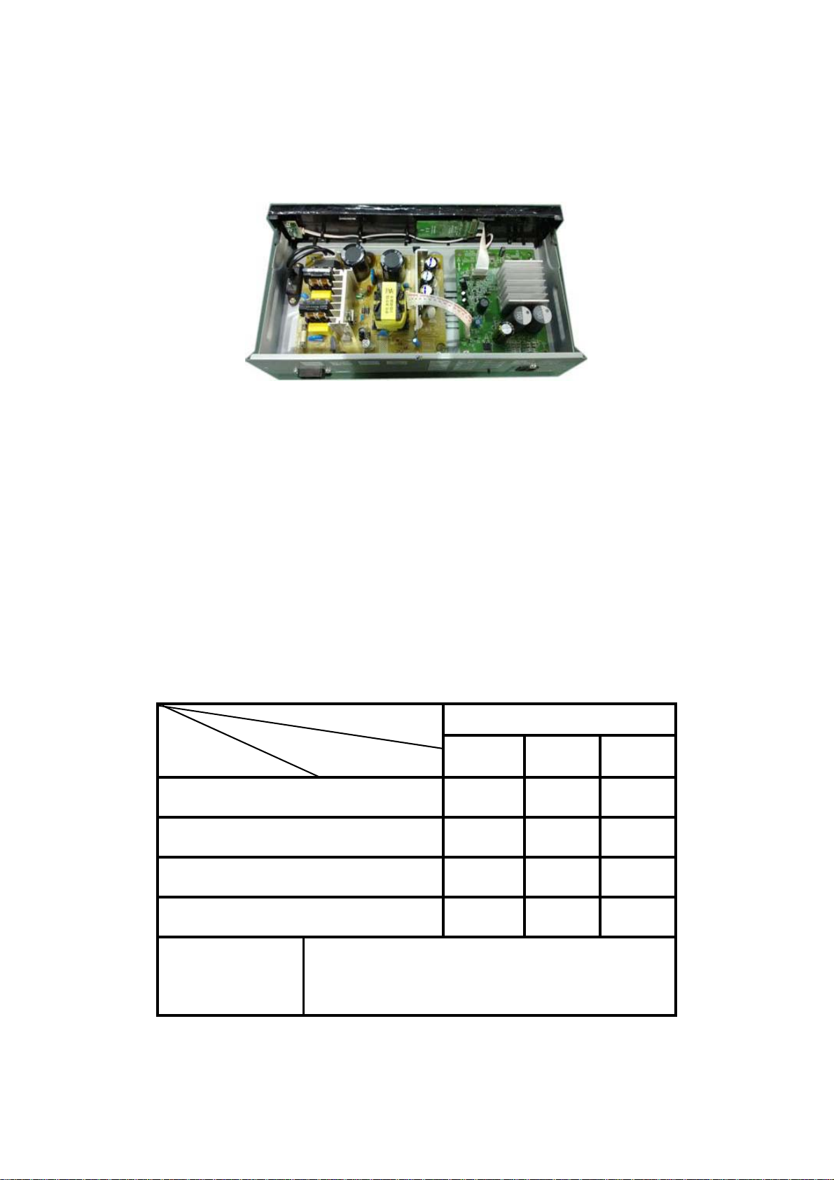
PCBA Locations of Main Unit:
Reminder: As BT and NFC need to be paired , and BT is on Front control board , when one of
BT , NFC or Front control Board needs to be replaced , all of these three parts need to be
replaced together.
VERSION VARIATIONS OF MAIN UNIT
Type / Versions
Board in used
MAIN BOARD
POWER BOARD
AMPLIFIER BOARD
FRONT CONTROL BOARD
NFC BOARD M
LOADER
*
Tips:
Service Policy
C -- Component Level Repair
M -- Module Level Repair
G/51
M
C
C
C
MTOUCH BOARD
M
HTB5550
/98
M
M
M
M
C
C
C
/78
M
C
C
C
M
M
M
Page 3
1-2
AMPLIFIER BOARD
POWER BOARD
LED BOARD
PCB Board Locations of Wireless BoxPCB Board Locations of Wireless Box
VERSION VARIATIONS OF WIRELESS BOX
Type / Versions
Board in used
AMPLIFIER BOARD
POWER BOARD
LED BOARD
Tips:
*
Service Policy
C -- Component Level Repair
M -- Module Level Repair
G/51
M
M
M
HTB5550
/98
M
M
M
/78
M
M
M
Page 4
o
2-1
GENERAL DESCRIPTION
Home Theater BD DVD with Tuner,AUX,MP3,MIC,HDMI OUT,Optical,Coaxial,ARC,RJ45.
HTB3XXX&HTB5XXX 6*166W(10%) 3ohm For Power Amplifier,VFD Display,Aux in ,AudioIN,MIC
in,FM,USB,HDMI(ARC),OpticalIN,BT,Remote control
LIFETIME : Years
Class
I N/A N/A
II
III
Page 9
SAFETY requirements
Version
IEC60065:2001+A1:2005+A2:2010
EN 60065:2002 + A1:2006
+A11:2008+A2:2010+A12:2012
CE
GB8898-20119 GB13837-2003(IEC/CISPR13:2001,MOD)
3C
Safety and EMC will be in accordance with the latest standards.
RADIATION / IMMUNITY
CLIMATIC requirements
ALL climates
MODERATE climates : + N.A till N.A Degree
PERFORMANCE CLASSES
POWER SUPPLY
MAINS ( A.C. ) 96-264V 196~264V 196-310V 96-132V
Version
Frequency
Tuner Supply + Amplifier Clock CD-mp3RecorderUSB
N/A
Y Y Y
3-6
Safety EMC for LAN Network (RJ45)
EN55013:2001+A1:2003+A2:2006,EN61000-32:2006+A1:2009+A2:2009,EN61000-3-3:2008,EN
55020:2007(IEC6100-4-2:2008,IEC 6100-43:2008,IEC6100-4-4:2004+Cor 1:2006+Cor
2:2007)
: + 0 Dregree till + 40 Degree
/55,77,/78/98,
50/60Hz
/12,/40,/51,/79,/93
EMC
/94 /F7
50/60Hz
N/A
50/60Hz50/60Hz
N/A N/A
POWER CONSUMER
TB35x0&HTB55x0 Versi
Stadby(Normal) : < 0.5W
Stand By(Fast wake up): <7.5W
( DEMO mode " OFF " ) , NOM. A, INPUT
Maximum :
@ 1/8 Prated , NOM. A, INPUT N/A
N/AECO Power mode :
Quality : % ( Major ) % ( Mirror )
Reliability : % ( C 42 )
Tested according to General Test Instruction refer to PHILIPS standary
Measured according to PHILIPS standary ( UAN - L1059 ) unless other wise stated
All not mentioned date, please refer to PHILIPS standary ( XUW - 0010 - JUNE 2001 )
DERIVED
Remarks
REMARKS APPROBATION
Page 5

2-2
TECHNIAL DESCRIPTION
HTB3XXX&HTB5XXX/12 Total power 1000W(THD10%), matching SPEAKER of 6x 3Ohm
INPUT SOURCE: BD/DVD/CD/OPTICAL/ARC/TUNER/AUX /USB/MP3//COAXIAL
GENERAL PART
OUTPUT stage Protection : Yes Temperature : Yes. Short circuit : Yes
LoudSpeaker D.C. Protection : No
INDICATORS
Standby Mode Indicator :LED(RED) Display
ECO Mode Indicator : No
ELECTRICAL DATA
TBC
MAX N/A
Limit Unit
3Channel Difference at -40dB dBSmart sound
<200
nWHum ( Volume Minimum to max -20dB ) ( Except MIC )
N/A
IS :
VAC :
VAC :
INTERCONNECTS
Input Sensitity(
Tuner
MP3 Line in
DVD
AUX intput
OUTPUT POWER ( * 1 ) At THD = 10% (Measured with 20Hz-20KHz filter), Test Frequency at 1KHz and at 10k )
Power output ( RMS )
N/A
N/A
N/A
±
2 dB)rated ouput power at 1 kHz and 10kHz.
:
FM 67.5KHZ Modulation -6dB
:
Nor: 1V Limit:0.9-1.1V
:
-6dB Track Audio disc1 trk35
Nor: 2V Limit:1.8-2.2V
:
HTB35x0/12
Hum ( For MIC only ) <200
Residual Noise ( Volume Minimum ) nW
Channel Separation ( at 1 kHz ) ( Except MP3 )
Channel Separation ( at 1 kHz ) ( For MP3 only) ≥55 dB
Signal / Noise ( For MIC only )
Line Output Voltage ( *1 )
Line Out ( Left / Right )
Scard output N.A
Digital Coaxial Out
Video output
HTB35x0/12 166W pre channel ( Lim '±0.5dB ) ≥148W
FR/FL /SR/SL/C/Sub channel
pre channel
nW
<40
≥60
≥ 60Signal / Noise ( Except MIC )
≥55 dB
N.A
N.A
N.A
dB
dB
OUTPUT POWER ( * 1 ) At THD = 30% (Measured with 20Hz-20KHz filter), Test Frequency at 1KHz and at 10k )
FR/FL /SR/SL/C/Sub channel
LOUDSPEAKER ( BOXES ) Please to package document of Speaker Box Assy
Rated Impedance
FL/FR/SR/SL/CET : 3Ohms at 150Hz to 20 KHz
Subwoofer : 3Ohms at 20Hz to 150Hz
Remarks
test condition: the AutoVolume off.
( *1 ) Electrical parameters are to be measuremend at specker terminals across 3 Ohm load ( pure resistor 3*1.33 ohm )
with rated input signal in AUX mode; DSC setting in CLASSIC mode
Measuremend output power only for AUX model and DVD model of used audio analyzer equipment.
GENERAL PART 1 - TECHNAICAL SPECICFICATION
Page 6
AUDIO SIGNAL PROCESSING
1 ) DSC ( Digital Sound Control )
Select AUX as input source with the following set conditions:
Inject sine wave 2V for All version at 1 KHz to L/R channels of AUX-IN socket.
2-3
Preset EQ
Rock Party
Jazz
70Hz
500Hz
16kHz
Bass & Treble setting :
Dolby virtual speaker :
2 ) Stretch performance requirement (for Europe)
wide mode to be use.
Sound Mode
Classic Sports News Night
Page 7
Video(CVBS) Performance
Description NTSC PAL
2-4
Amplitude output
White bar
Sync amplitude
Burst amplitude
Burst/Chroma ratio
S/N luminance
S/N chroma AM:≧54dB/PM:≧54dB
Video bandwidth
Chroma subcanics frequency
Chroma/Luminance delay ≦50ns
Subcanics locked/unlocked Locked
Mp3 performance
description ESS
Bit rates 8K-320Kps
1.0Vpp(+10/-15%) 1.0Vpp(+10/-15%)
714mVpp(+10/-15%)
286mVpp(±107mV) 300mVpp(±100mV)
286mVpp(+1dB/-4dB)
±10%
≧55dB
6Mhz(-6dB) 6Mhz(-6dB)
fsc=3.579545Mhz(±30ppm)
700mVpp(+10/-15%)
300mVpp(+1dB/-4dB)
±10%
≧55dB
AM:≧55dB/PM:≧52dB
fsc=4.433618Mhz(±30ppm)
≦50ns
locked
Sampling rates 8K/11.025K/16K/22.05K/32K/44.1K/48K Hz
Joliet (8 character OSD display)
Windows XP
UDF basic (close format)
Mp3 multisession Directory resting Max 8 level, Max directory 32
Display filename/ID3
255 folders/640songs
Page 8
A
TECHNIAL DESCRIPTION
TUNER used RZ5B705 soultion
GENERAL PART
2-5
WAVE RANGE
FM( 55/78 ) 87.5- 108.00 MHz
FM( 51 ) 87.5 - 108.00 MHZ
AERIAL
FM : No
AM : No
INDICATORS
LED
ELECTRICAL DATA
TUNING GRID
100 kHz
50KHZ
50KHZFM( 12/98/93 ) 87.5- 108.00 MHZ
ELECTRICAL DAT
AM Nor Limit Unit FM Nom Limit Unit
-3dB Limiting Point
17.5 23.5 dBf
AGC Figure of Merit dB
Overall distortion 100%
Distortion (RF 50 mV, M 80%)
%
IF kHz
FM Image Rejection (s/n 26 dB)
VAR MAX SENS VS Supply(AC±10%):
Spurious Response Rejection
dB
dB
IF
FM Channel Seprantion -400/1K/5K
Modulation Hum dB Stereo Switching Point:
2nd IF HAR REJ I/P:1.5~50mV/m dB
3rd IF HAR REJ I/P:1.5~50mV/m dB AM Suppression
Search Tuning Sensitivity
Search TU Stop Accuracy(RF≧1V/m)
dB Modulation Hum
Step
Overall Frequency
Response -6dB:
Search Time Sec Search Tuning Sensitivity
MW 26dB Quieting sensitivity
MW Selectity S9
-3 dB bandwidth
uV/m
FM 26dB Quieting sensitivity
dB FM S/N Ratio(A weighted) stereo input 80dBf:
KHZ FM S/N Ratio(A weighted) Mono input 80dBf:
125Hz:
10KHZ
2 3%
30 25 dB
300 ±0.02 KHz
26/3
20/2
0/20
6/18 dB
17.5 23.5 dBf
35 30 dB
55 45 dB
200 100 HZ
12 10 KHZ
24 35 dBf
18 22 dBf
60 55 dB
60 55 dB
Page 9
3
6HUYLFH+LQWV
&$87,21
&+$5*('&$3$&,7256217+(6(592%2$5'0$<'$0$*(7+('5,9(
(/(&7521,&6:+(1&211(&7,1*$1(:'5,9(7+$7¶6:+<%(6,'(67+(6$)(7<
0($685(6/,.(
6:,7&+2))32:(56833/<
(6'3527(&7,21
$'',7,21$/$&7,2160867%(7$.(1%<7+(5(3$,57(&+1,&,$1
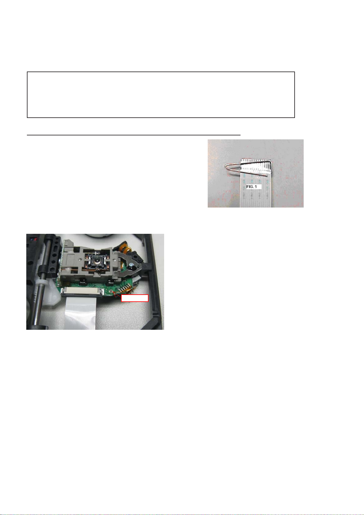
7KHIROORZLQJVWHSVKDYHWREHGRQHZKHQUHSODFLQJWKHGHIHFWLYHORDGHU
'LVPDQWOLQJRIWKHORDGHUWRDFFHVVWKH(6'SURWHFWLRQSRLQWLIQHFHVVDU\
6ROGHUWKH(6'SURWHFWLRQSRLQW
'LVFRQQHFWÀH[IRLOFDEOHIURPWKHGHIHFWLYHORDGHU
3XWDSDSHUFOLSRQWKHÀH[IRLOWRVKRUWFLUFXLWWKHFRQWDFWV¿J
5HSODFHWKHGHIHFWLYHORDGHUZLWKDQHZORDGHU
5HPRYHSDSHUFOLSIURPWKHÀH[IRLODQGFRQQHFWLWWRWKHQHZORDGHU
5HPRYHVROGHUMRLQWRQWKH(6'SURWHFWLRQSRLQW
$77(17,217KHODVHUGLRGHRIWKLVORDGHULVSURWHFWHGDJDLQVW(6'E\DVROGHUMRLQWZKLFKVKRUWFLUFXLWVWKHODVHUGLRGHWRJURXQG
)RUSURSHUIXQFWLRQDOLW\RIWKHORDGHUWKLVVROGHUMRLQWPXVWEHUHPRYHDIWHUFRQQHFWLRQORDGHUWRWKHVHW
Solder Joint
2QO\DSSOLFDEOHIRUGHIHFWLYHORDGHUQHHGHGWREHVHQWEDFNWRVXSSOLHUIRUIDLOXUHDQDO\VLVDQGWRVXSSRUWEDFNFKDUJLQJ
HYLGHQFH
7KLVLVDOVRDSSOLFDEOHIRUDOOSDUWQHUVKLSZRUNVKRSV
(6'SURWHFWLRQSRLQWLVDFFHVVLEOHIURPWRSRIORDGHU
Page 10

4‐1
Softwareupgrade
1.BuildafoldernameasUPGunderrootmenuofUSBdevice.
3.CopytheHTB5580.binfile(upgradefile)totherootmenuofUSBdevice.
4.ConnecttheUSBdevicetoHTS,
5.PoweronDUT,enterintoHOMEUI.
6.EnterintoSetupmenuselectAdvance>>Softwareupgrade>>USB.IftheupgradeSWwasfound,itwill
promptstartupgradeSW,plspressokselectStart.
7.Don’tpoweroffDUT.DUTwillrestartafterSWupgradecompleted.
Caution:Thesetmustnotbepoweroffduringupgrading,OtherwisetheMainboardwillbedamaged
entirely.
Softwareversioncheck
1. PoweronDUT,enterintohomeui,
2. Selectsetup>>advance>>versioninformation
3. ThemainsoftwareisSystemSW,MCUversionisSubsystemSW.
RestoreDUT
1. PoweronDUT,enterintoHOMEUI
2. Selectsetup>>advance>>Restoredefaultsettings
Page 11
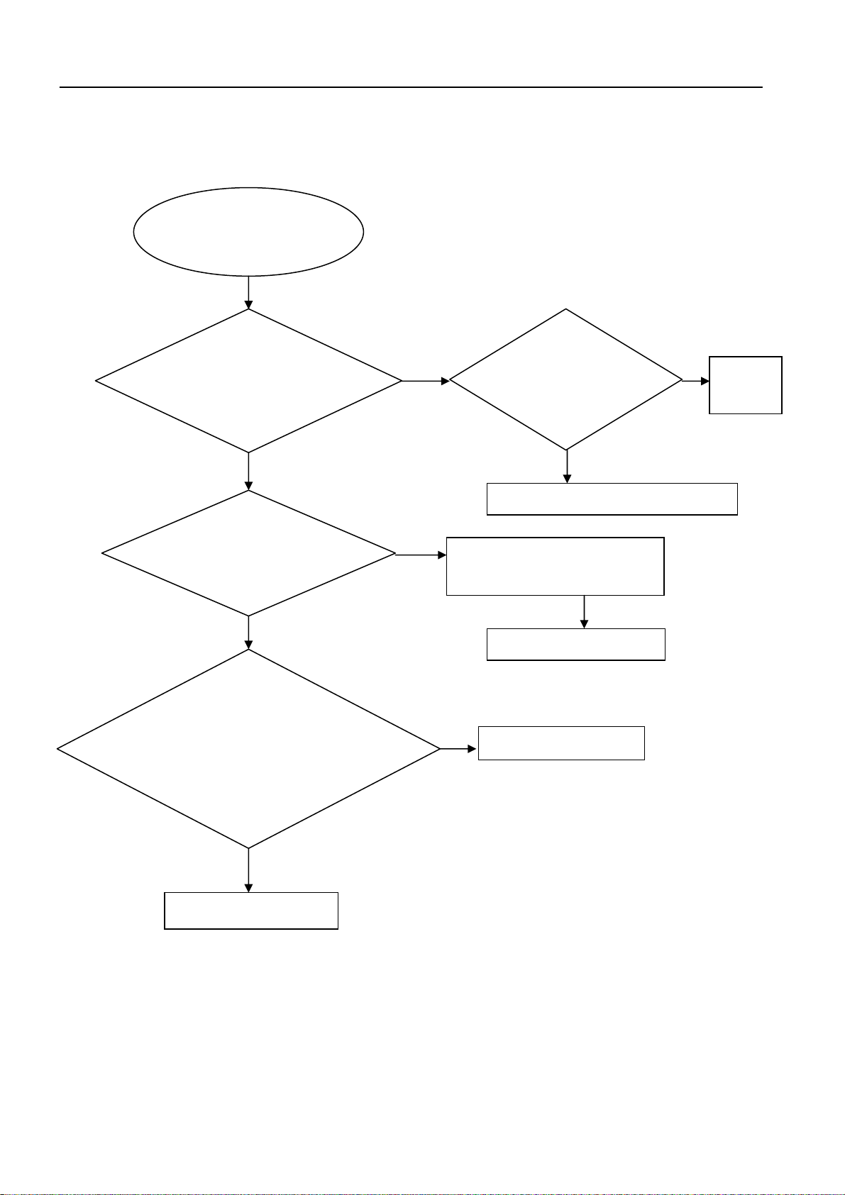
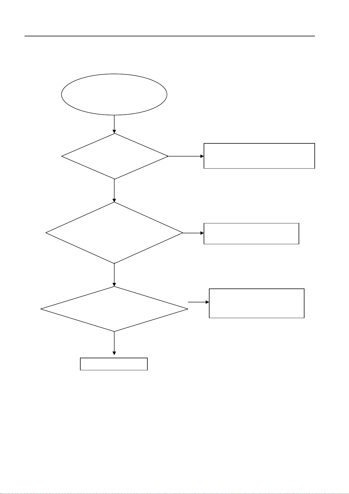
No display on VFD, and buttons do not work
5- 1
Trouble shooting chart
No display on VFD, and
buttons do not work
Yes
Check FV board U1
pin14
It should be 5V
Check xp9 pin17
in main board
It should be 12V
NO
No
Replace
U14
Yes
Check the front board
signals
(XP11 : pin13,14,15)
VCLK,VDATA,VSTB
No
Check the main board SPI signal
(U8 :pin41,40,39)
Yes
Replace +5VA circuit (ZD2,FB21)
Yes
NO
Replace Main Board
1.Check the VFD board
whether bad solder exists on
U1 and pins of VFD
2.Check whether the circuit
connected to AC1, AC2 are
broken.
No
Correct connection
Yes
Replace U1 or VFD circuit
Page 12

)
)
(
)
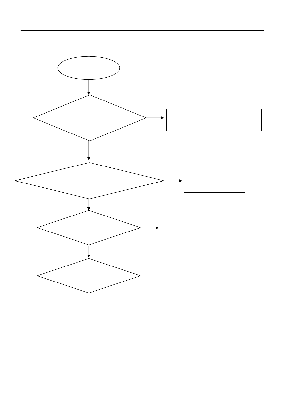
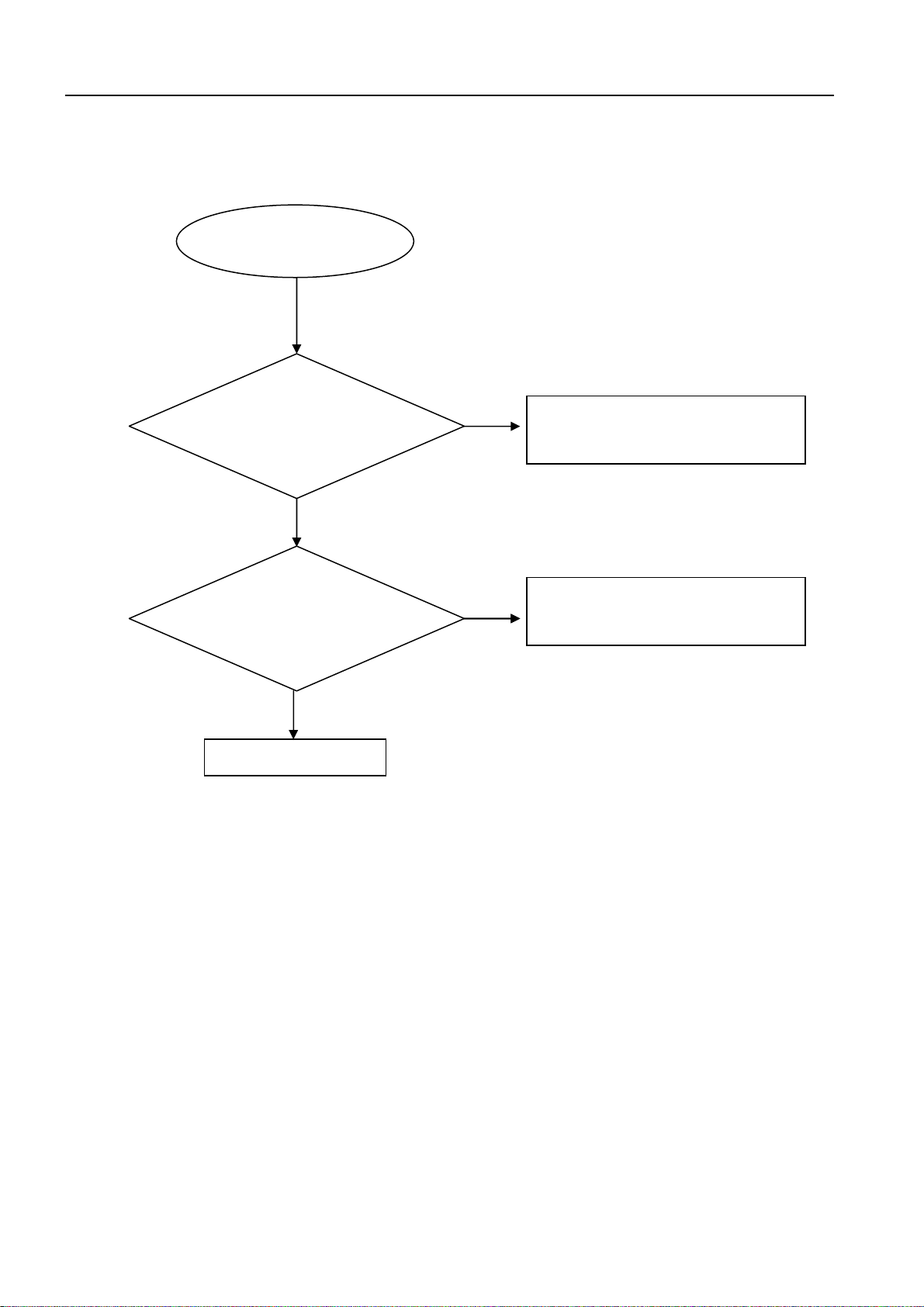
No audio output
No audio output
5- 2
Trouble shooting chart
Yes
Check 34v voltage on
AMP board is normal
NO
Refer to <
output
>
NO +34V
Yes
Check the signals of I2S
(R195,R196,R197,
R198,R199,R200
NO
Replace main board
Yes
Check the processor I2S signals
(U12 Pin 23,11,22,24,25,26)
NO
Check the PCB Layout
Yes
Check the PWM signals (U12
Pin38,39,40,41,42,43,44,45,46,47,48,
49
NO
Replace U12
Yes
Check the AMP IC Output
U632,U633,U634
NO
Replace U632,U633,U634
Yes
Replace the speaker
Page 13
Remote control does not work
In the front control board,check
IR601 pin1 Waveform
Remote control
does not work
Go
Check whether the remote
controller’s battery is
exhausted or not.
NO
In the main board U8 pin
10& R106 waveform
YES
Replace main board
Yes
5- 3
NO
Yes
Replace the battery for remote controller
NO
Check the pcb layout
Replace IR601
Trouble shooting chart
Page 14
r
5- 4
Trouble shooting chart
Can’t read disc or can’t open the disk door
Can’t read disc or can’t
open the disk door
GO
Check whether the
loader running is
normal
Yes
Check 24pin cable from
main board connection to
the loader is normal
Yes
Check if U409
(pin3,18,24,56) voltage is
normal
Yes
NO
NO
Check the connection 4pin cable from the
main board
Fix the connection the 24pin cable
NO
Replace main board
Replace the loade
Page 15
No HDMI output
No HDMI output
Go
Check if the HDMI
connector
Yes
5- 5
No
ImgBurn (key)
ImgBurn (key)
Trouble shooting chart
Check if the software
have KEY
No
ImgBurn (key)
Yes
Replace the main board
Page 16

No output by Optical in
Check power supply circuit
No output by Optical in
Go
Check the Optical
connector J3
Yes
Yes
Replace U27
5- 6
No
Trouble shooting chart
Fix J3 in mainboard
No
Check FB11 or system power
supply
Page 17

No output by Aux IN
No output by Aux in
Go
Check U18 pin4 ,11
Yes
Check U26 pin1 , 2
Yes
5- 7
No
No
Fix
Aux In
Replace U18
Trouble shooting chart
line to main board
Check U26 I2S output
pin9 , 10,11,12
Yes
Replace Main board
No
Replace U26
Page 18

6-1
Mechanical and Dismantling Instructions
Dismantling Instruction
The following guidelines show how to dismantle the player.
Detailed information please refer to the model set.
Step 1:Open the top cover.Remove 4 screws on the back panel, dismantle the left and right baffle,
then open the top cover.(Figure 1)
(Figure 1)
Step 2:Dismantle the loader.Open the CD tray and dismantle the CD door. Disconnect the connectors on
the main board. Remove 2 screws beside the loader.(Figure 2)
(Figure 2)
Page 19

6-2
Mechanical and Dismantling Instructions
Dismantling Instruction
The following guidelines show how to dismantle the player.
Detailed information please refer to the model set.
Step 3:Diamantle the front panel.Release the WI-FI module from the panel. Disconnect all the connectors.
Release 4 buckles on the left,right and bottom sides.(Figure 3)
(Figure 3)
Step 4:Diamantle the front control board.Remove 4 screws on the board.Lossen the board and disconnect
2 connectors on the inner side of the board,then pull out the board.(Figure 4)
(Figure 4)
Step 5:Diamantle the power board.Remove 4 screws and 1 plane interpolation on the board.(Figure 5)
(Figure 5)
Step 6:Diamantle the amplifier board.Remove 2 screws on the board and 1 screw on the back panel.
Step 7:Diamantle the main board.Remove 2 screws on the board and 3 screws on the back panel.(Figure 6)
(Figure 6)
Page 20

6-3
Mechanical and Dismantling Instructions
Dismantling Instruction
The following guidelines show how to dismantle the wireless box.
Detailed information please refer to the model set.
Step 1:Open the top cover. Remove 2 screws on the back panel.then open the cover.(Figure 1)
(Figure 1)
Step 2:Dismantle the front panel.Disconnect all the connectors on the boards.Release 4 buckles on
the left,right and bottom sides .(Figure 2)
(Figure 2)
Page 21

6-4
Mechanical and Dismantling Instructions
Dismantling Instruction
The following guidelines show how to dismantle the wireless box.
Detailed information please refer to the model set.
Step 3:Dismantle the power board.Remove 3 screws on tha board and 2 screws on the back panel.
Step 4:Dismantle the main board.Remove 2 screws on tha board and 1 screw on the back panel.(Figure 3)
(Figure 3)
Page 22

167W
THD10%
WirelessTXModule
PWM
I2S2
CS8416
TAS5538DGG
AUXIN
I2C2
U8
Driver(TI2050)
4I/O
USB
Powersupply
ASA9828+SANYO416
7-1 7-1
HTB5XXXMT8560BDHTS(1000WTHD10%)SystemBlock
ARCIN
HDMIOUT
RJ45
WIFI
MT7601
AVMD6100
*
BTL
6
LF
3ɏ
SUB
COAXAL
OPTICAL
FM
MIC
MP3IN
ROMBT
NFC
Main Board
U27
DIR
I2C1
U18U20
Source
Switch1
4052
U406
OP2
AK5358
SW3
U3/U4
I2S3
I2C0
U26
I2S1
U409
Motor
FV Board
U1
MPEGDECODER
MT8560
I2S1
RF
IR
CEC
4I/O
DDR3
2GbX1U2
2GbX1U3
U410
FLASH
I2S1
7I/OControl
MCU
WT61P8
12MHz
IR
2Gb
I2C4
SPI
I2C3
E2PROM
IR
U1
VFDDRIVER
VFD8Ͳchar
I2C5
FAN
U34
TouchKey
Audio
Processor
u12
PowerStage
TAS5624A
U634
PWM
PowerStage
TAS5624A
U633
AMP Board
TC Board
BTL
BTL
BTL
LF
LF
LF
3ɏ
3ɏ
3ɏ
FL
FR
CEN
BDLOADER
Power Board
4Control
+12V
power
signal
other
GND +34V
Page 23

A
AMP IC
A
PWM
IIS
IIC
Design)
1Pai
1Pai
g
7-2 7-2
HTB5XXXWirelessBoxSystemBlock
BTL
Main Board
Wireless RX module
AVMD6100
r
KEY
3.3V
LED
2I/O
2I/O
U301
udio
IIC
(Compatible
MCU
STM8S003F3
r
processor
TAS5538
IIC
4I/O
3.3V
12V
U632
TAS56
24
166W(3ȍ) 10%
BTL
167W(3ȍ) 10%
Compatible Design
power
U630 EUP3453(DC-DC)
POWER SUPPLY +34V
signal
other
+34V
Page 24

8-1 8-1
Wiring Diagram for HTB5550:
FM
XP7
45PIN 0.5MM
(TPIC2050)
COAXAL OPTICAL
DIR
CS8416
J11
8pin
0.5mm
P2
n2.0mm
4pin
HDMIOUT
Main Board
Main Board
RJ45
MT8560
FLASH
2Gb
MCU
AUXIN
DDR3
2GbX1
2GbX1
XP13
XP13
XP4
24pin0.5mm
2
Wi l OUT
WirelessOUT
ExternalTX
XP13
24PIN0.5mm
XP1
Audio
24pin0.5mm
2
P
Processor
TAS5538DGG
FAN
AMP Board
PowerStage
TAS5624A
PowerStage
TAS5624A
5.1OUT
PowerStage
TAS5624A
TRAVERS
(SANYO416)
LOAD
Wifi
J12
5pin 2.0mm
XP6
4PIN2.0mm
24PIN 0 5
BT
24PIN0.5mm
XP9
24PIN0.5mm
TC Board
TC Board
XP11
5pin
con
n607
1.0mm
6PIN 2.0mm
pin2.0mm
5p
IR
IR
6PIN2.0mm
5pin2.0mm
CON501
VFDDRIVER
VFD8Ͳchar
h
6PIN 2 0
6PIN2.0mm
Front Board
XP3
CON502
PowerBoard
2PIN 1.25mm
3 5mm JackDual Karaoke
3.5mmJackDualKaraoke
XS581
4PIN2.0MM
XP10
USB
NFC
NFC
Page 25

9-1 9-1
Circuit Diagram - Touch Board:
A
1 1
2 2
IR_Out
SDA
SCL
B
R96 0R96 0
R95 0R95 0
PAD1PAD1
R1
5.6KR15.6K
PAD2PAD2
R2
5.6KR25.6K
PAD3PAD3
R3
5.6KR35.6K
PAD4PAD4
R4
5.6KR45.6K
C
U1
1
TXD
2
VPP
3
SNS9
4
SNS8
5
PC7
6
PC6
7
PC5
8
PC4
AS9050U1AS9050
COUT
GND
VD
VCC
PC0
PC1
PC2
PC3
16
15
14
1uFC21uF
13
12
POWER/STANDBY Input
11
10
9
R5
5.6KR55.6K
PAD5PAD5
PAD6PAD6
C1
C1
4700pF/50V/X7R
4700pF/50V/X7R
C2
R6
R7
+12V_D
5.6KR65.6K
5.6KR75.6K
PAD7PAD7
R98
R98
R90 30KR90 30K
R97 10R97 10
C3
0.1uFC30.1uF
12K
12K
3.3V_STBY_MCU
R91 30KR91 30K
R92
R92
12K
12K
Q7
C4
C4
0.1uF/25V/Y5V
0.1uF/25V/Y5V
3.3V_STBY_MCU
R93
R93
470
470
LED_RED
LED_RED
NPN_3DG3904MQ7NPN_3DG3904M
LED1
LED1
D
E
STOP
VOL-
VOL+
SOURC
POWER
PAUSE
OPEN/CLOSE
CON606
CON606
5pin/1.0mm
5pin/1.0mm
1
1
2
IR_Out
2
3
3
4
4
5
5
R94 0R94 0
3.3V_STBY_MCU
+12V_D
SDA
SCL
3 3
4 4
A
B
C
D
E
Page 26

9-2 9-2
Circuit Diagram - Front Control Board:VFD
A
30
1
1
2
2
GND29GND
3
3
4
4
5
5
6
6
7
7
8
8
9
9
10
10
11
11
12
12
13
1 1
13
14
14
15
15
16
16
17
17
18
18
19
19
20
20
21
21
22
22
23
23
24
24
25
25
26
26
GND27GND
26PIN/0.5mm
26PIN/0.5mm
28
XP11
XP11
R103
R103
NC/0
NC/0
A
C2NC/10pF/50V/NP0 C2NC/10pF/50V/NP0
C1NC/10pF/50V/NP0 C1NC/10pF/50V/NP0
C3NC/10pF/50V/NP0 C3NC/10pF/50V/NP0
C4NC/10pF/50V/NP0 C4NC/10pF/50V/NP0
C5NC/10pF/50V/NP0 C5NC/10pF/50V/NP0
C6NC/10pF/50V/NP0 C6NC/10pF/50V/NP0
C7NC/10pF/50V/NP0 C7NC/10pF/50V/NP0
C8NC/10pF/50V/NP0 C8NC/10pF/50V/NP0
C9NC/10pF/50V/NP0 C9NC/10pF/50V/NP0
C10NC/10pF/50V/NP0 C10NC/10pF/50V/NP0
C11NC/10pF/50V/NP0 C11NC/10pF/50V/NP0
C15NC/10pF/50V/NP0 C15NC/10pF/50V/NP0
C13NC/10pF/50V/NP0 C13NC/10pF/50V/NP0
C14NC/10pF/50V/NP0 C14NC/10pF/50V/NP0
V_CLK
C68NC/10pF/50V/NP0 C68NC/10pF/50V/NP0
C69NC/10pF/50V/NP0 C69NC/10pF/50V/NP0
C67NC/10pF/50V/NP0 C67NC/10pF/50V/NP0
2 2
IRM_14mm
IRM_14mm
IR601
IR601
GND
VCC
GND
GND
1
IR
2
3
4
5
C21
C21
47pF/50V/NP0
47pF/50V/NP0
IR_IN
R34 100R34 100
R35 10KR35 10K
C22
C22
0.1uF/16V/Y5V
0.1uF/16V/Y5V
3.3V_STBY_MCU
B
IR_IN
BT_ADUIO_EN
BT_STATUS
BT_RESET
V_CLK 8
V_DATA 8
V_STB 8
OPEN/CLOSE
MP3_BT_L 7
MP3_BT_R 7
MIC_in2 7
MIC_in1 7
BT_STATUS_PAIR
POWER_CONTROL
BT_ADUIO_EN
BT_STATUS
BT_RESET
BT_3V3
NFC_FD
-24V_D
+12V_D
3.3V_STBY_MCU
POWER
FN1
NFC
NFC_FD
3
R104 NC/0R104 NC/0
R105 NC/0R105 NC/0
NFC
NFC_FD
R99 0R99 0
R96 0R96 0
R1181MR118
SCL
SDA
1M
R2 18KR2 18K
Q8
Q8
PNP_3CG3906M
PNP_3CG3906M
C64
C64
10uF/10V/Y5V
10uF/10V/Y5V
+5VA
Q2
Q2
NPN_3DG3904M
NPN_3DG3904M
C16
C16
1000pF/50V/X7R
1000pF/50V/X7R
3.3V_STBY_MCU
R95
R95
10K
10K
4.7UF/10V/X5R
4.7UF/10V/X5R
R1
10KR110K
NPN_3DG3904M
NPN_3DG3904M
R94
R94
10K
10K
R98
R98
10K
10K
Q7
Q7
DS
N_2SK3018
N_2SK3018
G
C65
C65
Q1
Q1
R100 0R100 0
C
C17 0.1uF/50V/X7RC17 0.1uF/50V/X7R
R5 4.7KR5 4.7K
R31KR3
1K
R41KR4
1K
XP10
XP10
2PIN/1.25mm
2PIN/1.25mm
1
2
1
2
Q3
Q3
NPN_3DG3904M
NPN_3DG3904M
R6
10KR610K
GND3GND
4
D
VFD
MP3_BT_SW
+5VA
R22
R22
10K
10K
VFD
VFD_32P_VFD200824
VFD_32P_VFD200824
F21F222G53G64G75G86G97G108G11NC12P1
NP31G
4
AC1
34
35
36
37
38
39
40
41
42
43
44
R23
R23
10K
10K
P315P2
13
14
31
33
U1
U1
G632G5
G4
G3
G2
G1
VDD
DRIVER_VFD_CS6312EN
DRIVER_VFD_CS6312EN
LED4
LED3
LED2
LED1
GND
OSC
SW11SW22SW33SW44SDout5SDin6GND7SCLK8/CS9KEY110KEY2
R24
R24
4.7K
4.7K
+5VA
P416P517P618P719P8
-24V_D
LR24
26
27
VEE
SEG1328SEG1429SEG1530SEG16
21
20
23
SEG1024SEG1125SEG12
SEG6/K6
SEG5/K5
SEG4/K4
SEG3/K3
SEG2/K2
SEG1/K1
11
C59
C59
C62
C62
100pF/50V/NP0
100pF/50V/NP0
R25 10KR25 10K
R26 10KR26 10K
SEG9
22
SEG8
21
SEG7
20
19
18
17
16
15
14
VDD
13
KEY4
12
KEY3
100pF/50V/NP0
100pF/50V/NP0
R27 10KR27 10K
R28 10KR28 10K
P1427P1528NC29NP30F131F1
NC26P1325P1224P1123P1022P9
C60
C60
100pF/50V/NP0
100pF/50V/NP0
R29 10KR29 10K
R30 10KR30 10K
C61
C61
100pF/50V/NP0
100pF/50V/NP0
R31 10KR31 10K
R32 10KR32 10K
10UF/50VCE1+10UF/50VCE1
-24V_D
ZD2
ZD2
BZV55C5V1/5.1V
BZV55C5V1/5.1V
AC2
R10
R10
2.2
2.2
R11 470R11 470
ZD1
ZD1
ZMM6V2/6.2V
ZMM6V2/6.2V
4.7uF/16V/Y5V
4.7uF/16V/Y5V
C18
C18
R18 100R18 100
R19 100R19 100
R20 100R20 100
R13 330R13 330
R12
R12
10K
10K
+5VA+12V_D
C19
C19
0.1uF/50V/X7R
0.1uF/50V/X7R
R17
R17
51K
51K
R21
R21
10K
10K
R14 5.6R14 5.6
CE2
CE2
+
+
10UF/50V
10UF/50V
+12V_D
R90R9
R8
0
470R8470
+12VA
Q4
Q4
R7
NPN_3DG3904M
NPN_3DG3904M
470R7470
+
Q5
Q5
PNP_3CG3906M
PNP_3CG3906M
FB240FB24
R15 1KR15 1K
0
R16 1KR16 1K
V_DATA
V_CLK
V_STB
E
32
AC2
+5VA
C20
C20
4.7uF/16V/Y5V
4.7uF/16V/Y5V
D100
LL4148
LL4148
D101
D101
LL4148
LL4148
D100
SW1
SW1
<Description>
<Description>
SW2
SW2
<Description>
<Description>
SW3
SW3
<Description>
<Description>
SW4
SW4
<Description>
<Description>
SW5
SW5
<Description>
<Description>
C57
1K
1K
+12V_D
C57
NC/100pF/50V/NP0
NC/100pF/50V/NP0
SW6
SW6
<POWER>
<POWER>
SW7
SW7
<OPEN/CLOSE>
<OPEN/CLOSE>
C58
C58
NC/100pF/50V/NP0
NC/100pF/50V/NP0
C66
P581
P581
6
VCC
Shell B
D
Shell A
USB-A/BK
USB-A/BK
5
DD+
GND
R38 0R38 0
R107 0R107 0
R110 0R110 0
3.3V_STBY_MCU
R93
R93
680
680
LED1
NPN_3DG3904MQ6NPN_3DG3904M
LED1
LED_RED
LED_RED
C
+12V_D
R90 10KR90 10K
Q6
R92
R92
10K
10K
B
C66
10UF
10UF
1
2
3
4
ESD21ESD21
ESD22ESD22
2 1
2 1
USB_VCC
USB_VCC
4
4
3
3
2
2
1
1
4PIN/2.0mm/200mm
4PIN/2.0mm/200mm
XS581
XS581
To main board
E
3 3
IR_IN
R1060R106
0
R361KR36
R371KR37
SDA
SCL
3.3V_STBY_MCU
POWER
OPEN/CLOSE
1
1
2
CON607
CON607
5pin/1.0mm
5pin/1.0mm
2
3
3
4
4
5
5
4 4
A
Page 27

9-3 9-3
Circuit Diagram - Front Control Board:Bluetooth
A
1 1
2 2
B
Bluetooth
BT_RESET
BT_RESET
MISOMISO
MOSIMOSI
BT_CLKBT_CLK
CSBCSB
GNDGND
BT_3V3
2
R39
R39
100K
100K
C23
C23
D
BT_3V3
R112 1KR112 1K
R400R40
0
1uF/16V/Y5V
1uF/16V/Y5V
R113NC/0R113NC/0
TP32TP32
BT_RSTBT_RST
C74 1.8pfC74 1.8pf
R87
R87
NC/0
NC/0
D
D
BM830U7BM830
U7
1
GND
2
AIO0
3
PIO14
4
PIO15
5
PIO16
6
PIO17
7
PIO10
8
SCL
9
PIO11
10
PIO12
11
PIO13
12
SPI/PCM
13
GND
14
PIO3/MISO
15
PIO2/MOSI
16
PIO5/CLK
17
PIO4/CSB
18
GND
R71 1KR71 1K
R89 1KR89 1K
R88
R88
NC/0
NC/0
52
57
56
55
54
SPR_LP
SPR_LN
SRP_RP
BT_STATUS_PAIR
2
50
53
51
AGND
SPR_RN
LINE_BP
LINE_AP
LINE_BN
MIC_BIAS
PIO31_LED2
PIO8/UART_RTS
PIO1/UART_TX
PIO0/UART_RX
PIO9/UART_CTS
3V3_OUT
1V8_OUT
R114
R114
47K
47K
POWER_CONTROL
60RF59
58
GND
GND
GND19RESET20GND21PIO30/LED122PIO29/LED023VREGENABLE24GND25VBUS26CHG_EXT27VBAT_SENSE28VBAT29GND
BT_STATUS
2
49
LINE_AN
PIO18
PIO21
PIO6
PIO7
GND
USB_DP
USB_DN
GND
VDD
30
BT_3V3
A
GND
C26
C26
0.1uF/16V/Y5V
0.1uF/16V/Y5V
D
C
A
R47 9.1KR47 9.1K
R45 9.1KR45 9.1K
R43 9.1KR43 9.1K
R41 9.1KR41 9.1K
R422KR42
2K
48
47
46
45
44
43
42
41
40
39
38
37
36
35
34
33
32
31
TP18TP18
R117
R117
D
NC/0
NC/0
R70 1KR70 1K
R111 1KR111 1K
R97 1KR97 1K
BT_TXBT_TX
BT_RXBT_RX
TM39TM39
TM40TM40
C24
C24
10uF/10V/Y5V
10uF/10V/Y5V
FN1
NFC
BT_3V3
R1160R116
0
C25
C25
DD
0.1uF/16V/Y5V
0.1uF/16V/Y5V
BT_ADUIO_EN
A
FN1
NFC
2
C73 1000pF/50V/X7RC73 1000pF/50V/X7R
C71 1000pF/50V/X7RC71 1000pF/50V/X7R
D
C72 1000pF/50V/X7RC72 1000pF/50V/X7R
C70 1000pF/50V/X7RC70 1000pF/50V/X7R
D
R462KR46
2K
R442KR44
2K
A
A
2K
R482KR48
C27
C27
C28
C28
C29
C29
C30
C30
D
R49 10KR49 10K
4.7uF/10V/Y5V
4.7uF/10V/Y5V
R50 10KR50 10K
4.7uF/10V/Y5V
4.7uF/10V/Y5V
R51 10KR51 10K
4.7uF/10V/Y5V
4.7uF/10V/Y5V
R52 10KR52 10K
4.7uF/10V/Y5V
4.7uF/10V/Y5V
+12V_D
R57 1KR57 1K
C33 100pF/50V/NP0C33 100pF/50V/NP0
A
A
R53 100KR53 100K
-
-
2
1
+
+
3
U406A
U406A
AS4558M
8 4
84
5
+
+
6
-
-
A
R54 100KR54 100K
AS4558M
7
U406B
U406B
AS4558M
AS4558M
R58
R58
4.7K
4.7K
C34
C34
0.1uF/16V/Y5V
0.1uF/16V/Y5V
R55
R55
100K
100K
BT_REFM
R56
R56
100K
100K
CE4
CE4
+
+
220uF/16V
220uF/16V
A A
C31
C31
4.7uF/10V/Y5V
4.7uF/10V/Y5V
C32
C32
4.7uF/10V/Y5V
4.7uF/10V/Y5V
BT_R
BT _12V
BT_REFMBT _12V
R63
R63
4.7K
4.7K
BT_L
C35
C35
22uF/10V/Y5V
22uF/10V/Y5V
A
E
JACK605
JACK605
MIC JACK
MIC JACK
3 3
JACK604
JACK604
6PIN/H-ɎDIP3.5-09
6PIN/H-ɎDIP3.5-09
4 4
1
1
6
6
3
3
5
5
4
4
2
2
1
1
6
6
3
3
5
5
4
4
2
2
R72 0R72 0
A
R73 0R73 0
A
R101
R101
NC/0
NC/0
A
MIC1
R77
R77
680
680
R74
R74
R75 13KR75 13K
MIC2
A
CE6
CE6
13K
13K
+
+
2.2uF/25V
2.2uF/25V
C43
C43
1000pF/50V/X7R
1000pF/50V/X7R
R102 2.2KR102 2.2K
R33 0R33 0
CE7
CE7
+
R76
R76
680
680
+
2.2uF/25V
2.2uF/25V
R78
R78
REF1
CE8
CE8
220uF/16V
220uF/16V
C44
C44
1000pF/50V/X7R
1000pF/50V/X7R
C45
C45
2
3
REF1
-
-
+
+
8 4
+
+
A
C46
C46
R79
R79
2
3
47pF/50V/NP0
47pF/50V/NP0
91K
91K
A
1
U5A
U5A
AS4558M
AS4558M
12VA
C63
C63
0.1uF/16V/Y5V
0.1uF/16V/Y5V
47pF/50V/NP0
47pF/50V/NP0
A
-
-
+
+
8 4
12VA
12VA+12V_D
91K
91K
1
2.2uF/16V/Y5V
2.2uF/16V/Y5V
R83 22KR83 22K
U6A
U6A
AS4558M
AS4558M
C47
C47
C49
C49
100pF/50V/NP0
100pF/50V/NP0
R84
R84
22K
22K
A
C48
C48
2.2uF/16V/Y5V
2.2uF/16V/Y5V
C50
C50
REF1
R80
R80
100K
100K
C51
C51
NC/100pF/50V/NP0
NC/100pF/50V/NP0
R81
R81
20K
20K
A
REF1
R85
R85
100K
100K
100pF/50V/NP0
100pF/50V/NP0
84
5
+
+
6
-
-
R82
R82
C55
C55
C53
C53
2.2uF/10V/Y5V
2.2uF/10V/Y5V
CE5
CE5
+
+
220uF/16V
220uF/16V
A
5
6
C52
C52
NC/100pF/50V/NP0
NC/100pF/50V/NP0
R86
R86
20K
20K
C54
C54
2.2uF/10V/Y5V
2.2uF/10V/Y5V
A
7
U5B
U5B
AS4558M
AS4558M
47pF/50V/NP0
47pF/50V/NP0
84
+
+
-
-
R108
R108
C56
C56
120K
120K
7
MIC_in1
U6B
U6B
AS4558M
AS4558M
120K
120K
47pF/50V/NP0
47pF/50V/NP0
MIC_in2
MIC_in1
MIC_in2
USB_VCC
MP3_BT_SW 3
MP3_BT_R
MP3_BT_L
AA
2
2
R66 100R66 100
R67 100R67 100
R65
R65
47K
47K
USB_VCC
C38
C38
0.1uF/16V/Y5V
0.1uF/16V/Y5V
FB230FB23
0
A
C39
C39
2.2uF/10V/Y5V
2.2uF/10V/Y5V
C40
C40
2.2uF/10V/Y5V
2.2uF/10V/Y5V
MP3_R
MP3_L
R61
R61
100K
100K
A A
JACK602
JACK602
6PIN/H-ɎDIP3.5-09
6PIN/H-ɎDIP3.5-09
1
2
1
2
MP3_R
R59 1MR59 1M
C41
C41
1uF/16V/Y5V
1uF/16V/Y5V
R62
R62
100K
100K
A
R60 1MR60 1M
R68 1MR68 1M
R69 1MR69 1M
BT_R
MP3_L
BT_L
B2
S
GND
VCC
B13A
U3
U3
74LVC1G3157GV
74LVC1G3157GV
B2
S
GND
VCC
B13A
U4
U4
74LVC1G3157GV
74LVC1G3157GV
1
6
3
5
4
2
6
R109 4.7KR109 4.7K
5
4
C36
C36
2.2uF/10V/Y5V
2.2uF/10V/Y5V
R115
R115
NC/0
NC/0
6
MP3_R
5
4
C37
C37
2.2uF/10V/Y5V
2.2uF/10V/Y5V
R119
R119
NC/0
NC/0
MP3_L
1
6
3
5
4
2
R64
R64
47K
47K
A
B
C
D
E
Page 28

Circuit Diagram - Power Board
9-4 9-4
A
1 1
CE518
CE518
0.47uF/63V
0.47uF/63V
Drain
NC
BP/M
C511
C511
4700pF/1KV
4700pF/1KV
C501
C501
4
3
2
1
R565
R565
100K
100K
HV
IC_VCC
D509
D509
1N4148
1N4148
R506
R506
2.2M
2.2M
HV
R5660R566
0
ZD503
ZD503
BZX79C12
BZX79C12
Q507
Q507
Q503
Q503
PNP_MMBT8550CLT1
PNP_MMBT8550CLT1
PNP_3CG3906M
PNP_3CG3906M
R563 150R563 150
R564 22KR564 22K
CE511
CE511
+
+
10uF/50V
10uF/50V
R562
R562
150K
150K
R507
CE501
CE501
+
+
330uF/200V
330uF/200V
JP507JP507
Alternative
CE502
CE502
+
+
330uF/200V
330uF/200V
R505 1MR505 1M
11
12
T501_P
10
T501_N
9
R507
470K
470K
R508
R508
JP508JP508 C502
470K
470K
Alternative
R509
R509
470K
470K
+
+
R584
R584
68uF/400V
68uF/400V
470K
470K
R583 1MR583 1M
U501
U501
5
S
6
S
7
S
S8EN/UV
TNY179PN
TNY179PN
Alternative
CN502
CN502
2PIN/7.92mm
2PIN/7.92mm
112
2
JP506JP506
BD501
BD501
1
2 2
2
-+
-+
4
R503 1MR503 1M
CX502 0.22uF/275VACCX502 0.22uF/275VAC
CY503
CY503
100pF/250VAC
100pF/250VAC
KBU610
KBU610
R504 1MR504 1M
3 3
CX501 0.22uF/275VACCX501 0.22uF/275VAC
R502 1MR502 1M
R501 1MR501 1M
RV501 VDR/560VRV501 VDR/560V
TR501
TR501
NTC/3ohm/5A
NTC/3ohm/5A
CN501
CN501
2
112
CY502
CY502
4 4
100pF/250VAC
100pF/250VAC
CY501
CY501
3
LIF502
LIF502
6.6MH
6.6MH
CY504
CY504
100pF/250VAC
100pF/250VAC
LIF501
LIF501
6.6MH
6.6MH
2PIN/7.92mm
2PIN/7.92mm
T_GND
1000pF/250VAC
1000pF/250VAC
Alternative
AC
F501
F501
FUSE_6.3A/250V
FUSE_6.3A/250V
+
+
68uF/400V
68uF/400V
T501_HV
T501_D
T501_VCC
T501_GND
CE517
CE517
JP505JP505
Alternative
6
5
4
3
2
1
RV502
RV502
VDR/240V
VDR/240V
RV503
RV503
VDR/240V
VDR/240V
AC
T5012
T5012
EF25
EF25
B
HV
R510 NC/2MR510 NC/2M
R511 NC/2MR511 NC/2M
R5870ȍR587
0ȍ
IC_VCC
R560
R560
R561
R561
150K
150K
150K
150K
ZD505
ZD505
BZX79C18
BZX79C18
D510 1N4148D510 1N4148
R559
R559
150K
150K
C513
C513
NC/100pF/1KV
NC/100pF/1KV
TOP261EN
TOP261EN
R514
R514
NC/12K
NC/12K
C521
C521
ZD507
ZD507
0.0022uF(222)400V
0.0022uF(222)400V
R55822R558
NC/P6KE200A
NC/P6KE200A
22
D504
D504
FR107/1A/1000V
FR107/1A/1000V
VCC
CE510
CE510
+
+
47uF/35V
47uF/35V
R515
R515
22K
22K
D506
D506
FR207/2A/1000V
FR207/2A/1000V
U502
U502
D505
D505
FR107/1A/1000V
FR107/1A/1000V
C506
C506
0.0022uF(222)400V
0.0022uF(222)400V
R51722R517
R51622R516
22
22
D507
D507
FR207/2A/1000V
FR207/2A/1000V
V
V
D
D
CONTROL
CONTROL
X
X
S
S
R538 0R538 0
T501_HV
T501_D
ZD508
ZD508
R51822R518
NC/P6KE200A
NC/P6KE200A
22
Optional
C
C
F
F
R51947R519
C5050.1uF/50V/X7R C5050.1uF/50V/X7R
47
CE503
CE503
+
+
CY506 1000pF/250VACCY506 1000pF/250VAC
T501
T501
NC/EEL19
NC/EEL19
6 8
4
2
T501_VCC
1
T501_GND
R572
R572
470
470
12
43
2
U504
U504
3
IC_3P_431A
IC_3P_431A
VCC
R5220R522
R5260R526
0
0
CE504
CE504
+
+
47uF/50V
47uF/50V
470UF/16V
470UF/16V
D501 BAS316/100V/0.5AD501 BAS316/100V/0.5A
D502 MBRX120/20V/1AD502 MBRX120/20V/1A
R575 NC/22R575 NC/22
R576 NC/22R576 NC/22
11
C523
C523
NC/1000pF/1KV
NC/1000pF/1KV
10
T501_P
D516 SR3100/3A/100VD516 SR3100/3A/100V
D518 SR3100/3A/100VD518 SR3100/3A/100V
9
T501_N
R571
R571
U509
U509
2.2K
2.2K
LTV-817S-B
LTV-817S-B
1
CY505 NC/470pF/250VACCY505 NC/470pF/250VAC
1
2
3
5
D503
D503
6
FR107/1A/1000V
FR107/1A/1000V
R521 12KR521 12K
R520 100R520 100
ZD502
ZD502
ZD509
ZD509
BZX79C12
BZX79C12
BZX79C39V
BZX79C39V
C522 NC/1000pF/1KVC522 NC/1000pF/1KV
D515 NC/HER203G/2A/200VD515 NC/HER203G/2A/200V
D517 NC/SR3100/3A/100VD517 NC/SR3100/3A/100V
R573 NC/22R573 NC/22
R574 NC/22R574 NC/22
BD DVD
R567 21.5K 12.4K
R568 13K 12K
R569 10K \
C525 NC/220pFC525 NC/220pF
C524 0.1uF/50V/X7RC524 0.1uF/50V/X7R
VDD
N.C
D
P-GND
FB
43
T502
T502
PQ3230
PQ3230
CE514
CE514
+
+
1000UF/25V
1000UF/25V
C
C507 2200pF/1KVC507 2200pF/1KV
1
8
A8
9
A9
3
D514 SF20A300HPI/20A/300VD514 SF20A300HPI/20A/300V
ZD504
ZD504
BZX79C12
BZX79C12
10
A10
12
A12
T_GND
R5231KR523
1K
R524
R524
12
2.2K
2.2K
U507
U507
LTV-817S-B
LTV-817S-B
2
U503
U503
3
IC_3P_431A
IC_3P_431A
CE512
CE512
+
+
NC/1000UF/25V
NC/1000UF/25V
L502 3.3uH/3AL502 3.3uH/3A
CE515
CE515
+
+
1000UF/25V
1000UF/25V
R570 10KR570 10K
JP509
JP509
NC/Jumper
NC/Jumper
2
1
470uF/16V
470uF/16V
R527
R527
2.2/2W
2.2/2W
CE505
CE505
+
+
820uF/50V
820uF/50V
R525 100KR525 100K
CE513
CE513
+
+
NC/470uF/16V
NC/470uF/16V
CE516
CE516
C519
C519
+
+
0.1uF/50V/X7R
0.1uF/50V/X7R
R569
R569
10K/1%
10K/1%
CE506
CE506
+
+
820uF/50V
820uF/50V
R599
R599
R528
R528
2.7K
2.7K
C509 NC/220pFC509 NC/220pF
C508 0.1uF/50V/X7RC508 0.1uF/50V/X7R
R532
R532
3.01K/1%
3.01K/1%
C518
C518
NC/0.1uF/50V/X7R
NC/0.1uF/50V/X7R
R567
R567
21.5K/1%
21.5K/1%
R568
R568
13K/1%
13K/1%
CE507
CE507
+
+
820uF/50V
820uF/50V
R530
R530
24K/1%
10 mR
10 mR
+5V
24K/1%
R529
R529
2.7K
2.7K
OPP
R531
R531
4.7K/1%
4.7K/1%
NPN_MMBT8050CLT1
NPN_MMBT8050CLT1
+12V
R577
R577
NC/6.8K
NC/6.8K
PNP_MMBT8550CLT1
PNP_MMBT8550CLT1
+5V LOOPLOOPLOOP
PCON
R581 10KR581 10K
R579
R579
4.7K
4.7K
R580
R580
NPN_MMBT8050C
NPN_MMBT8050C
C527
C527
0.1uF/50V/X7R
0.1uF/50V/X7R
10K
10K
Q509
Q509
Q508
Q508
C510
C510
0.1uF/50V/X7R
0.1uF/50V/X7R
D511
D511
1N4148
1N4148
Q504
Q504
R582
R582
10K
10K
R549
R549
D512
D512
1N4148
1N4148
33K
33K
CE508
CE508
+
+
22uF/50V
22uF/50V
R539 1.5KR539 1.5K
R540
R540
1.5K
1.5K R541
C516
C516
0.1uF/50V/X7R
0.1uF/50V/X7R
1.5K/1%
1.5K/1%
CE509
CE509
+
+
NC/22uF/16V
NC/22uF/16V
2.2K/1%
2.2K/1%
C526
C526
0.1uF/50V/X7R
0.1uF/50V/X7R
+34V+34V_1
U508
U508
LTV-817S-B
LTV-817S-B
R553
R553
R554
R554
VCC
43
R541
2.2K
2.2K
R5421KR542
1K
TR502
TR502
NTC/10Kohm
NTC/10Kohm
0.1uF/50V/X7R
0.1uF/50V/X7R
C514
C514
D
LOOP
8
V+
V+
3
+
+
2
-
-
V-
V-
<Package>
<Package>
4
LM3580
C502
0.1uF/50V/X7R
0.1uF/50V/X7R
LOOP
R5431KR543
1K
12
LOOP
R550
R550
2.2K/1%
2.2K/1%
R552 100KR552 100K
R555
R555
2.2K/1%
2.2K/1%
LM3580
U506A
U506A
R537 100K/1%R537 100K/1%
C504 0.01uF/50V/X7RC504 0.01uF/50V/X7R
R5461KR546
1K
PNP_3CG3906M
PNP_3CG3906M
Q501
Q501
NPN_3DG3904M
NPN_3DG3904M
0.1uF/50V/X7R
0.1uF/50V/X7R
8
V+
V+
5
+
+
6
-
-
V-
V-
<Package>
<Package>
4
LM3580
LM3580
U506B
U506B
Q502
Q502
C520
C520
D508 1N4148D508 1N4148
1
C503
C503
0.1uF/50V/X7R
0.1uF/50V/X7R
+34V
ZD501
ZD501
BZX79C39V
BZX79C39V
R547
R547
680
680
OTP
R548
R548
220
220
D513
D513
7
1N4148
1N4148
OP
R536 2.4K/1%R536 2.4K/1%
C515
C515
0.1uF/50V/X7R
0.1uF/50V/X7R
OP
OTP
R557
R557
R5560R556
NC/680
NC/680
0
+34V_1
R5880R588
OPP
0
OPP
R551
R551
NC/0
NC/0
BD: R545=47K
DVD: R545=6.8K
D520
D520
BAS316/100V/0.5A
BAS316/100V/0.5A
E
NC/10PIN/2.0mm/200mm
NC/10PIN/2.0mm/200mm
1
PCON
1
2
+12V
2
3
3
4
4
5
+5V
5
6
6
7
7
8
8
9
9
10
+34V
10
11
11
12
12
CON504
CON504
C0N501
C0N501
1
PCON
1
2
2
3
3
4
+5V
4
5
5
4PIN/2.0mm/160mm
4PIN/2.0mm/160mm
C0N502
C0N502
1
+34V
1
2
2
3
3
4
4
5
5
6
6
4PIN/2.0mm/160mm
4PIN/2.0mm/160mm
CON503
CON503
1
1
2
GND
2
NC/2PIN_2.5
NC/2PIN_2.5
C529 0.1uF/50V/X7RC529 0.1uF/50V/X7R
Q510
Q510
R54547K R54547K
NPN_3DG3904M
NPN_3DG3904M
C528
C528
0.1uF/50V/X7R
0.1uF/50V/X7R
LOOP
R544
R544
150K
150K
TR506
TR506
100K
100K
A
B
C
D
E
Page 29

9-5 9-5
Circuit Diagram - Amplifier & NFC Board:DSP
A
NC/4.7KR1NC/4.7K
R24 0R24 0
R22 0R22 0
+3.3V
R1
R3
R2
4.7KR34.7K
4.7KR24.7K
R13 47R13 47
R14 47R14 47
R15 47R15 47
R16 47R16 47
R17 47R17 47
R18 47R18 47
R19 47R19 47
R20 47R20 47
WL_SDA
WL_SCL
ADD FB8 AND +12V-FAN
NET FOR FAN
24PIN/0.5mm
24PIN/0.5mm
25
1 1
TOP
TOP
TO MAIN BOARD
27
+12V-FAN
26
D
1
2
3
4
5
6
7
GND
8
9
10
11
12
RESET
13
DSP_MUTE
14
GND
15
I2C_SDA
16
I2C_SCL
17
GND
18
MCLK
19
GND
20
BICK
21
22
23
LRCLK
24
XP1
XP1
28
R217 33R217 33
R12 0R12 0
TP1TP1
TP2TP2
TP3TP3
TP4TP4
TP5TP5
TP6TP6
500/800mA
500/800mA
TP7TP7
TP13TP13
DD
TP8TP8
TP9TP9
TP10TP10
TP11TP11
TP12TP12
TP14TP14
TP15TP15
TP16TP16
TP17TP17
TP18TP18
WL_IRQ
+5V/WL_RESET
+12V
+3.3V
R9 0R9 0
R10 0R10 0
R11 0R11 0
FB2500/800mA FB2500/800mA
FB3
FB3
R4
4.7KR44.7K
R5
4.7KR54.7K
R6
4.7KR64.7K
B
C30.01uF/50V/X7R C30.01uF/50V/X7R
C10.01uF/50V/X7R C10.01uF/50V/X7R
R7
R8
4.7KR74.7K
4.7KR84.7K
C610pF/50V/NP0 C610pF/50V/NP0
C510pF/50V/NP0 C510pF/50V/NP0
C810pF/50V/NP0 C810pF/50V/NP0
C910pF/50V/NP0 C910pF/50V/NP0
C710pF/50V/NP0 C710pF/50V/NP0
C40.01uF/50V/X7R C40.01uF/50V/X7R
C20.01uF/50V/X7R C20.01uF/50V/X7R
C1010pF/50V/NP0 C1010pF/50V/NP0
D
MCU_CON_FAN
PWDN
1/2power-control
TAS5538_RESET
M_MUTE
AMP_SDA
M_CLK
S_CLK
SDIN3
SDIN2
L_RCLK
SDIN1
C1110pF/50V/NP0 C1110pF/50V/NP0
C1210pF/50V/NP0 C1210pF/50V/NP0
AMP_SCL
C
SRS_CLK
SRSDOUT
SRL_RCLK
R21 47R21 47
R23 47R23 47
R25 47R25 47
SCLKO
SDOUT
LRCLKO
D
1
2
3
4
5
TOP
TOP
6
7
8
9
10
11
12
13
14
15
16
17
18
19
20
21
22
XP2
XP2
D
C3010pF/50V/NP0 C3010pF/50V/NP0
C3310pF/50V/NP0 C3310pF/50V/NP0
C3510pF/50V/NP0 C3510pF/50V/NP0
TP24TP24
WL_SDA
WL_SCL
LRCLKO
WL_RST
C3810pF/50V/NP0 C3810pF/50V/NP0
C3910pF/50V/NP0 C3910pF/50V/NP0
C4010pF/50V/NP0 C4010pF/50V/NP0
WL_IRQ
SCLKO
SDOUT
R27 47R27 47
C11410pF/50V/NP0 C11410pF/50V/NP0
C11510pF/50V/NP0 C11510pF/50V/NP0
0.1uF/50V/X7R
0.1uF/50V/X7R
TP23TP23
E
+5V/WL_RESET
M_CLK
R52 1R52 1
C29
C29
+
+
CE4
CE4
10uF/16V
10uF/16V
D
+3.3V
0.047uF/50V/Y5V
0.047uF/50V/Y5V
0.047uF/50V/Y5V
0.047uF/50V/Y5V
M_CLK
D
R216 33R216 33
D
LAYOUT NOTE:
EMI SNUBBER
PLACE TO THE
LEFT OF U100
C128 4700pF/50V/X7RC128 4700pF/50V/X7R
R39
R39
C68
C68
470
470
C122
C122
4700pF/50V/X7R
4700pF/50V/X7R
R157
R157
470
470
C95
C95
D
R158 12K/1%R158 12K/1%
TAS5538_RESET
PWDN
MUTE
AMP_SDA
AMP_SCL
L_RCLK
S_CLK
SDIN1
SDIN2
SDIN3
L1
L1
FB80@100MHz
FB80@100MHz
L2
L2
FB80@100MHz
FB80@100MHz
C42
C42
0.1uF/50V/X7R
0.1uF/50V/X7R
LAYOUT NOTE:
EMI SNUBBER
PLACE NEAR
J901 PIN 1
R269 0R269 0
R152 6.2K/1%R152 6.2K/1%
R156
R156
100K
100K
C143
C143
0.1uF/25V/Y5V
0.1uF/25V/Y5V
C34
C34
R73
R73
10K
10K
R81
R81
NC/3.3
NC/3.3
NC/0.1uF/50V/X7R
NC/0.1uF/50V/X7R
D
C131
C131
D
PVDD
C666
C666
0.01uF/50V/X7R
0.01uF/50V/X7R
U12
U12
1
PWM_HPM_L
2
PWM_HPP_L
3
PWM_HPM_R
4
PWM_HPP_R
5
AVSS
6
PLL_FLTM
7
PLL_FLTP
8
VR_ANA
9
AVDD
10
ASEL_VACS2
11
MCLK
12
OSC_RES
13
DVSS2_CORE
14
DVDD2_CORE
15
EMO_1
16
RESET
17
HP_SLE
18
PDN
19
MUTE
20
SDA
21
SCL
22
LRCLK
23
SCLK
24
SDIN1
25
SDIN2
26
SDIN3
27
SDIN4
28
VR_DIG
TAS5538DGG
TAS5538DGG
TSSOP56-DGG
TSSOP56-DGG
10uF/10V/Y5V
10uF/10V/Y5V
R450R45
0
D
RN2
RN2
33*4
33*4
RN3
RN3
33*4
33*4
RN1
RN1
33*4
33*4
D
+3.3V
C606
C606
D
100pF/50V/NP0
100pF/50V/NP0
D
C132
C132
0.1uF/25V/Y5V
0.1uF/25V/Y5V
R29 47R29 47
SRL_RCLK
SRS_CLK
SRSDOUT
Q6
Q6
PNP_MMBT8550CLT1
PNP_MMBT8550CLT1
R202 4.7KR202 4.7K
Q34
Q34
PNP_3CG3906M
PNP_3CG3906M
R163 10KR163 10K
R203 100KR203 100K
C129
C129
PM_A8SW
PM_B8SW
PM_A7FL
PM_B7FL
PM_A4FR
PM_B4FR
PM_A3CEN
PM_B3CEN
PM_A2SL
PM_B2SL
PM_A1SR
PM_B1SR
VALID 11,12,13
13
13
D
13
13
12
12
12
12
12
12
12
12
R252 33R252 33
/BKND_ERR
Q11
R257 100KR257 100K
C665
C665
1uF/10V/Y5V
1uF/10V/Y5V
Q11
NPN_3DG3904M
NPN_3DG3904M
C118
C118
0.1uF/25V/Y5V
0.1uF/25V/Y5V
PWM_P_6
PWM_M_6
PWM_P_5
PWM_M_5
VR_PWM
AVSS_PWM
AVDD_PWM
PWM_P_8
PWM_M_8
PWM_P_7
PWM_M_7
PWM_P_4
PWM_M_4
PWM_P_3
PWM_M_3
PWM_P_2
PWM_M_2
PWM_P_1
PWM_M_1
VALID
DVSS1_CORE
DVDD1_CORE
BKND_ERR
PSVC
TEST
LRCLKO
SCLKO
SDOUT
56
55
54
53
52
51
50
49
48
47
46
45
44
43
42
41
40
39
38
37
36
35
34
33
32
31
30
29
+12V-FAN
C121 0.1uF/25V/Y5VC121 0.1uF/25V/Y5V
1
2
346
1
2
346
1
2
346
R251 1KR251 1K
R262 0R262 0
8
7
5
8
7
5
8
7
5
TP21TP21
D
C5204.7uF/16V/Y5V C5204.7uF/16V/Y5V
MCU_CON_FAN
C84
C84
0.1uF/25V/Y5V
0.1uF/25V/Y5V
FAULT 12,13
R205
R205
4.7K
4.7K
R162
R162
1.2K
1.2K
0.1uF/25V/Y5V
0.1uF/25V/Y5V
+3.3V
C81
C81
C521NC/4.7uF/16V/Y5V C521NC/4.7uF/16V/Y5V
10uF/10V/Y5V
10uF/10V/Y5V
VCC_FAN
C670.1uF/25V/Y5V C670.1uF/25V/Y5V
FOR HTB5XXX
1
1
2
2
XP31
XP31
2PIN/2.0mm
2PIN/2.0mm
1
1
2
2
XP29
XP29
2PIN/2.0mm
2PIN/2.0mm
FOR HTB3XXX
TO FAN
D
2 2
+3.3V
R51
+3.3V
+3.3V
R26
R26
10K
10K
M_MUTE
3 3
C16
C16
0.1uF/50V/X7R
0.1uF/50V/X7R
+12V
D
+12V_D
+
+
CE2
CE2
47uF/16V
47uF/16V
TO SR&SL Wireless
AVMD6100
25
26
TOP
TOP
4 4
XP13
XP13
SMD0.5 TOP
SMD0.5 TOP
27
28
R255 1KR255 1K
C130
C130
D DD
0.1uF/50V/X7R
0.1uF/50V/X7R
+3.3V
C483
C483
+
+
CE482
CE482
0.1uF/25V/Y5V
0.1uF/25V/Y5V
22uF/16V
22uF/16V
C663
C663
C662
C662
10uF/10V/Y5V
TP34TP34
TP28TP28
10uF/10V/Y5V
FB17 500/500mAFB17 500/500mA
SR_PAIR WL_IRQ
0.1uF/25V/Y5V
0.1uF/25V/Y5V
WL_SCL
WL_SDA
SCLKO
LRCLKO
SDOUT
1
+5v
2
3
4
5
6
7
8
9
10
11
12
13
14
15
16
17
18
19
20
21
22
23
24
R254
R254
47K
47K
+5V/WL_RESET
Q10
Q10
NPN_3DG3904M
NPN_3DG3904M
R253 0R253 0
GNDWGNDW
D
TO SMPS
6PIN/2.0mm
6PIN/2.0mm
XP3
XP3
1
1
2
2
3
3
4
4
5
5
6
6
TP41TP41
+3.3V
R153
R153
10K
10K
TP42TP42
WIRE WIDE5MM
10uF/10V/Y5V
10uF/10V/Y5V
1/2power-control
2.2
2.2
C108
C108
C36
C36
NC/0.1uF/50V/X7R
NC/0.1uF/50V/X7R
LAYOUT NOTE:
EMI SNUBBER
PLACE TO THE
RIGHT OF U100
R51
C106
C106
0.1uF/25V/Y5V
0.1uF/25V/Y5V
C376
C376
0.1uF/25V/Y5V
0.1uF/25V/Y5V
D
C32
C32
C116
C116
NC/0.1uF/50V/X7R
NC/0.1uF/50V/X7R
NC/0.1uF/50V/X7R
NC/0.1uF/50V/X7R
A
B
C
D
E
Page 30

9-6 9-6
Circuit Diagram - Amplifier & NFC Board:SL+SW
A
B
C
D
E
only for HTB35XX series
D
0.1uF/50V/X7R
0.1uF/50V/X7R
0.1uF/50V/X7R
1 1
D
R649 1R649 1
R650 1R650 1
D
11,12,13
11
11
11
11
VALID
PM_A2SL
PM_B2SL
PM_A1SR
PM_B1SR
+12V_D
+12V_D
FAULT12,13,8
OTW12,13,8
2 2
+12V_D
+12V_D
R652 1R652 1
R653 1R653 1
D
D
+12V_D
+12V_D
11,12,13
VALID
11
3 3
PM_A4FR
11
PM_B4FR
11
PM_A3CEN
11
PM_B3CEN
FAULT12,13,8
OTW12,13,8
0.1uF/50V/X7R
C402
C402
C401
C401
R415 24KR415 24K
C166 0.1uF/50V/X7RC166 0.1uF/50V/X7R
C404 1UF/16V/X7RC404 1UF/16V/X7R
C405 1UF/16V/X7RC405 1UF/16V/X7R
R403 0R403 0
R404 0R404 0
D
R648 1R648 1
D
0.1uF/50V/X7R
0.1uF/50V/X7R
C409
C409
R405 24KR405 24K
C167 0.1uF/50V/X7RC167 0.1uF/50V/X7R
C475 1UF/16V/X7RC475 1UF/16V/X7R
C474 1UF/16V/X7RC474 1UF/16V/X7R
R418 0R418 0
R441 0R441 0
R651 1R651 1
C400 1UF/16V/X7RC400 1UF/16V/X7R
C406
C406
0.1uF/50V/X7R
0.1uF/50V/X7R
0.1uF/50V/X7R
0.1uF/50V/X7R
C403
C403
C408 1UF/16V/X7RC408 1UF/16V/X7R
D
1
2
3
4
5
6
7
8
9
10
11
12
13
14
15
16
17
18
19
20
21
22
D
1
2
3
4
5
6
7
8
9
10
11
12
13
14
15
16
17
18
19
20
21
22
GVDD_AB
VDD
OC_ADJ
RESET
INPUT_A
INPUT_B
C_START
DVDD
GND
GND
GND
GND
AVDD
INPUT_C
INPUT_D
FAULT
OTW
CLIP
M1
M2
M3
GVDD_CD
U632 TAS5624AU632 TAS5624A
GVDD_AB
VDD
OC_ADJ
RESET
INPUT_A
INPUT_B
C_START
DVDD
GND
GND
GND
GND
AVDD
INPUT_C
INPUT_D
FAULT
OTW
CLIP
M1
M2
M3
GVDD_CD
BST_A
BST_B
OUT_A
OUT_A
PVDD_AB
PVDD_AB
PVDD_AB
OUT_B
OUT_C
PVDD_CD
PVDD_CD
PVDD_CD
OUT_D
OUT_D
BST_C
BST_D
PVDD_AB
PVDD_AB
PVDD_AB
OUT_C
PVDD_CD
PVDD_CD
PVDD_CD
OUT_D
OUT_D
GND
GND
GND
GND
GND
GND
BST_A
BST_B
GND
GND
OUT_A
OUT_A
OUT_B
GND
GND
GND
GND
BST_C
BST_D
44
43
42
41
40
39
38
37
36
35
34
33
32
31
30
29
28
27
26
25
24
23
44
43
42
41
40
39
38
37
36
35
34
33
32
31
30
29
28
27
26
25
24
23
C440 0.033uF/50V/X7RC440 0.033uF/50V/X7R
C441 0.033uF/50V/X7RC441 0.033uF/50V/X7R
C410
C410
0.1uF/50V/X7R
0.1uF/50V/X7R
D
0.1uF/50V/X7R
0.1uF/50V/X7R
C412
C412
0.1uF/50V/X7R
0.1uF/50V/X7R
D
0.1uF/50V/X7R
0.1uF/50V/X7R
D
C442 0.033uF/50V/X7RC442 0.033uF/50V/X7R
C443 0.033uF/50V/X7RC443 0.033uF/50V/X7R
C470 0.033uF/50V/X7RC470 0.033uF/50V/X7R
C471 0.033uF/50V/X7RC471 0.033uF/50V/X7R
D
D
D
C472 0.033uF/50V/X7RC472 0.033uF/50V/X7R
C473 0.033uF/50V/X7RC473 0.033uF/50V/X7R
PVDD
C411
C411
PVDD
C413
C413
C449
C449
0.1uF/50V/X7R
0.1uF/50V/X7R
C448
C448
0.1uF/50V/X7R
0.1uF/50V/X7R
C456
C456
0.1uF/50V/X7R
0.1uF/50V/X7R
PVDD
C457
C457
0.1uF/50V/X7R
0.1uF/50V/X7R
PVDD
R42456R424
56
C414
C414
100pF/50V/NP0
100pF/50V/NP0
R42756R427
56
C415
C415
100pF/50V/NP0
100pF/50V/NP0
R43356R433
56
C450
C450
100pF/50V/NP0
100pF/50V/NP0
R43556R435
56
C454
C454
100pF/50V/NP0
100pF/50V/NP0
close to PVDD_AB close to PVDD_CD
PVDD
R426
R426
3.3
3.3
C434
C434
0.1uF/50V/X7R
0.1uF/50V/X7R
C435
C435
0.01uF/50V/X7R
0.01uF/50V/X7R
D
7uH
7uH
2
1
4 3
L401
L401
7uH
7uH
2
1
4 3
L402
L402
close to PVDD_AB close to PVDD_CD
PVDD
R434
R434
3.3
3.3
C453
C453
0.1uF/50V/X7R
0.1uF/50V/X7R
C452
C452
0.01uF/50V/X7R
0.01uF/50V/X7R
D
7uH
7uH
2
1
4 3
1
4 3
L403
L403
7uH
7uH
L404
L404
1uF//50V/X7R
1uF//50V/X7R
2
1uF//50V/X7R
1uF//50V/X7R
1000pF/50V/X7R
1000pF/50V/X7R
C140 0.22uF/50V/X7RC140 0.22uF/50V/X7R
C139 0.22uF/50V/X7RC139 0.22uF/50V/X7R
C418 1uF//50V/X7RC418 1uF//50V/X7R
1uF//50V/X7R
1uF//50V/X7R
C144 0.22uF/50V/X7RC144 0.22uF/50V/X7R
C145 0.22uF/50V/X7RC145 0.22uF/50V/X7R
C424
C424
1000pF/50V/X7R
1000pF/50V/X7R
C146 0.22uF/50V/X7RC146 0.22uF/50V/X7R
C147 0.22uF/50V/X7RC147 0.22uF/50V/X7R
C445
C445
C148 0.22uF/50V/X7RC148 0.22uF/50V/X7R
C149 0.22uF/50V/X7RC149 0.22uF/50V/X7R
C468
C468
PVDD PVDD
R428
R428
3.3
3.3
C436
C436
0.1uF/50V/X7R
0.1uF/50V/X7R
C437
C437
0.01uF/50V/X7R
0.01uF/50V/X7R
D
C425
C425
C420
C420
NC/1000pF/50V/X7R
NC/1000pF/50V/X7R
D
C423
C423
1000pF/50V/X7R
1000pF/50V/X7R
C426
C426
1000pF/50V/X7R
1000pF/50V/X7R
C429
C429
1000pF/50V/X7R
1000pF/50V/X7R
PVDD PVDD
C459
C459
0.1uF/50V/X7R
0.1uF/50V/X7R
D
C439
C439
C438
C438
1000pF/50V/X7R
1000pF/50V/X7R
C463
C463
1000pF/50V/X7R
1000pF/50V/X7R
C464
C464
1000pF/50V/X7R
1000pF/50V/X7R
R429
R429
3.3
3.3
C427
C427
NC/1000pF/50V/X7R
NC/1000pF/50V/X7R
D
C428
C428
NC/1000pF/50V/X7R
NC/1000pF/50V/X7R
R432
R432
3.3
3.3
D
C444
C444
NC/1000pF/50V/X7R
NC/1000pF/50V/X7R
D
R436
R436
3.3
3.3
C458
C458
0.01uF/50V/X7R
0.01uF/50V/X7R
C446
C446
NC/1000pF/50V/X7R
NC/1000pF/50V/X7R
D
C447
C447
NC/1000pF/50V/X7R
NC/1000pF/50V/X7R
D
C451
C451
NC/1000pF/50V/X7R
NC/1000pF/50V/X7R
D
C455
C455
NC/1000pF/50V/X7R
NC/1000pF/50V/X7R
D
C430
C430
0.01uF/50V/Y5V
0.01uF/50V/Y5V
C432
C432
0.01uF/50V/Y5V
0.01uF/50V/Y5V
D
C460
C460
0.01uF/50V/Y5V
0.01uF/50V/Y5V
R437
R437
3.3
3.3
R440
R440
3.3
3.3
CE439
CE439
+
+
820uF/50V
820uF/50V
D
CE438
CE438
+
+
820uF/50V
820uF/50V
C462
C462
0.01uF/50V/Y5V
0.01uF/50V/Y5V
C421
C421
1000pF/50V/X7R
1000pF/50V/X7R
D
R430
R430
3.3
3.3
C431
C431
0.01uF/50V/Y5V
0.01uF/50V/Y5V
D
R431
R431
3.3
3.3
C433
C433
0.01uF/50V/Y5V
0.01uF/50V/Y5V
C422
C422
1000pF/50V/X7R
1000pF/50V/X7R
D
R438
R438
3.3
3.3
C461
C461
0.01uF/50V/Y5V
0.01uF/50V/Y5V
D
R439
R439
3.3
3.3
C465
C465
0.01uF/50V/Y5V
0.01uF/50V/Y5V
SL+
SL-
SR+
SR-
13
FR+
CEN+
4
4
4
4
D D DD D D
C184
C184
C183
C152
C152
C165
C135
C135
C138
C138
0.22uF/50V/X7R
0.22uF/50V/X7R
0.22uF/50V/X7R
SUB+
SUB-13
FL+13
FL-13
FR+12
FR-12
CEN+12
CEN-12
SL+12
SL-12
SR+12
SR-12
4
CEN-
4
4
4
FR-
0.22uF/50V/X7R
C179
C179
C153
C153
0.22uF/50V/X7R
0.22uF/50V/X7R
DD D DD D
C165
0.22uF/50V/X7R
0.22uF/50V/X7R
C134
C134
0.22uF/50V/X7R
0.22uF/50V/X7R
0.22uF/50V/X7R
0.22uF/50V/X7R
C183
0.22uF/50V/X7R
0.22uF/50V/X7R
0.22uF/50V/X7R
0.22uF/50V/X7R
C170
C170
C171
C171
0.22uF/50V/X7R
0.22uF/50V/X7R
0.22uF/50V/X7R
0.22uF/50V/X7R
5.1CH 3.1CH 2.1CH
0.22uF/50V/X7R
0.22uF/50V/X7R
1
2
3
4
5
6
7
8
9
10
11
12
13
JK701
JK701
CON_13P_0GNDD
CON_13P_0GNDD
C169
C169
0.22uF/50V/X7R
0.22uF/50V/X7R
D DD
CON_9P_0GNDD
CON_9P_0GNDD
1
JK703
JK703
1
2
2
3
3
4
4
5
5
6
6
7
7
8
8
9
9
1
2
3
4
5
6
7
8
9
10
11
12
13
1
2
3
4
5
6
7
JK702JK702
1
2
3
4
5
6
7
U633 TAS5624AU633 TAS5624A
C407
C407
0.1uF/50V/X7R
D
0.1uF/50V/X7R
B
C
D
E
4 4
A
Page 31

9-7 9-7
Circuit Diagram - Amplifier & NFC Board:SL+SW
A
1 1
0.1uF/50V/X7R
0.1uF/50V/X7R
0.1uF/50V/X7R
0.1uF/50V/X7R
C508
C508
C477
C477
C497 1UF/16V/X7RC497 1UF/16V/X7R
R460 24KR460 24K
C168 0.1uF/50V/X7RC168 0.1uF/50V/X7R
C523 1UF/16V/X7RC523 1UF/16V/X7R
C522 1UF/16V/X7RC522 1UF/16V/X7R
R462 0R462 0
R463 0R463 0
D
+12V_D
R655 1R655 1
R656 1R656 1
D
D
R654 1R654 1
+12V_D
+12V_D
11,12,13
2 2
VALID
11
PM_A8SW
11
PM_B8SW
11
PM_A7FL
11
PM_B7FL
FAULT12,13,8
OTW12,13,8
B
D
10
11
12
13
14
15
16
17
18
19
20
21
22
1
2
3
4
5
6
7
8
9
GVDD_AB
VDD
OC_ADJ
RESET
INPUT_A
INPUT_B
C_START
DVDD
GND
GND
GND
GND
AVDD
INPUT_C
INPUT_D
FAULT
OTW
CLIP
M1
M2
M3
GVDD_CD
BST_A
BST_B
GND
GND
OUT_A
OUT_A
PVDD_AB
PVDD_AB
PVDD_AB
OUT_B
GND
GND
OUT_C
PVDD_CD
PVDD_CD
PVDD_CD
OUT_D
OUT_D
GND
GND
BST_C
BST_D
44
43
42
41
40
39
38
37
36
35
34
33
32
31
30
29
28
27
26
25
24
23
C509 0.033uF/50V/X7RC509 0.033uF/50V/X7R
C510 0.033uF/50V/X7RC510 0.033uF/50V/X7R
D
0.1uF/50V/X7R
0.1uF/50V/X7R
D
0.1uF/50V/X7R
0.1uF/50V/X7R
D
C512 0.033uF/50V/X7RC512 0.033uF/50V/X7R
C514 0.033uF/50V/X7RC514 0.033uF/50V/X7R
C486
C486
0.1uF/50V/X7R
0.1uF/50V/X7R
PVDD
C485
C485
C493
C493
0.1uF/50V/X7R
0.1uF/50V/X7R
PVDD
C494
C494
R44356R443
56
C487
C487
100pF/50V/NP0
100pF/50V/NP0
R44956R449
56
C491
C491
100pF/50V/NP0
100pF/50V/NP0
C
7uH
7uH
1
4 3
L405
L405
7uH
7uH
1
4 3
L406
L406
D
close to PVDD_AB close to PVDD_CD
PVDD
R448
R448
3.3
3.3
C490
C490
0.1uF/50V/X7R
0.1uF/50V/X7R
C489
C489
0.01uF/50V/X7R
0.01uF/50V/X7R
D
2
C481 1uF//50V/X7RC481 1uF//50V/X7R
2
1uF//50V/X7R
1uF//50V/X7R
C506
C506
C141 0.22uF/50V/X7RC141 0.22uF/50V/X7R
C142 0.22uF/50V/ X7RC142 0.22uF/50V/X7R
1000pF/50V/X7R
1000pF/50V/X7R
C136 0.22uF/50V/X7RC136 0.22uF/50V/X7R
1000pF/50V/X7R
1000pF/50V/X7R
1000pF/50V/X7R
1000pF/50V/X7R
C502
C502
C137 0.22uF/50V/ X7RC137 0.22uF/50V/X7R
1000pF/50V/X7R
1000pF/50V/X7R
C479
C479
C478
C478
C501
C501
R451
R451
3.3
3.3
D
D
C469
C469
NC/1000pF/50V/X7R
NC/1000pF/50V/X7R
R457
R457
3.3
3.3
D
C482
C482
NC/1000pF/50V/X7R
NC/1000pF/50V/X7R
D
C498
C498
0.01uF/50V/Y5V
0.01uF/50V/Y5V
C500
C500
0.01uF/50V/Y5V
0.01uF/50V/Y5V
PVDD PVDD
R450
R450
3.3
3.3
C496
C496
0.1uF/50V/X7R
0.1uF/50V/X7R
C495
C495
0.01uF/50V/X7R
0.01uF/50V/X7R
D
D
C488
C488
0.1uF/50V/X7R
0.1uF/50V/X7R
R452
R452
3.3
3.3
D
C492
C492
0.1uF/50V/X7R
0.1uF/50V/X7R
C499
C499
0.01uF/50V/Y5V
0.01uF/50V/Y5V
D
R453
R453
3.3
3.3
C503
C503
0.01uF/50V/Y5V
0.01uF/50V/Y5V
SUB+
SUB-
FL+
FL-
820uF/50V
820uF/50V
D
4
4
4
4
CE440
CE440
+
+
C480
C480
1000pF/50V/X7R
1000pF/50V/X7R
E
U634 TAS5624AU634 TAS5624A
C476
D
C476
0.1uF/50V/X7R
0.1uF/50V/X7R
3 3
4 4
A
B
C
D
E
Page 32

9-8 9-8
Circuit Diagram - Power Board for Wireless Box
A
1 1
C513
C513
C511
C511
103/400V
103/400V
R526
R526
NC/0
NC/0
HV
U502
U502
CE501+
R507
Alternative
CE501
CE501
+
+
470uF/200V
470uF/200V
CE501-
JP507JP507
Alternative
Alternative
RV503
RV503
+
+
VDR/240V
VDR/240V
R507
470K
470K
R508
R508
470K
470K
CE502+
CE502
CE502
470uF/200V
470uF/200V
CE502-
JP508JP508
Alternative
R509
R509
470K
470K
R512
R512
470K
470K
BD501
BD501
1
2
-+
-+
4
KBU610
KBU610
Alternative
CN502
CN502
2PIN/7.92mm
2PIN/7.92mm
JP506JP506
112
2
Alternative
230VAC\115VAC 䖜ᦒ
3
JP505JP505
Alternative
RV502
RV502
VDR/240V
VDR/240V
2 2
100pF/1KV
CE502+
CE5021
CE5021
100uF/450V
100uF/450V
100pF/1KV
LIF502
LIF502
24MH
24MH
R504 1MR504 1M
R503 1MR503 1M
CX502 0.22uF/275VACCX502 0.22uF/275VAC
AC
CY503
CY503
470pF/250VAC
470pF/250VAC
LIF501_4
LIF501_1
3 3
TR501
TR501
NTC/3ohm/5A
NTC/3ohm/5A
CY502
CY502
NC/100pF/250VAC
NC/100pF/250VAC
CY504
CY504
470pF/250VAC
470pF/250VAC
LIF501
LIF501
2 3
LIF501_3
Alternative
1 4
LIF501_2
24MH
24MH
CX501 0.22uF/275VACCX501 0.22uF/275VAC
R502 1MR502 1MR5011MR501
1M
RV501 VDR/560VRV501 VDR/560V
2
N1L
CN5011
CN5011
PWR JACK
PWR JACK
2
CN501
CN501
112
NC/ 2PIN/7.92mm
NC/ 2PIN/7.92mm
F501
F501
FUSE_6.3A/250V
FUSE_6.3A/250V
Alternative
CE501+
CE5011
CE5011
+
+
+
+
100uF/450V
100uF/450V
CE501- CE502-
Alternative
LIF5011NCLIF5011
3 4
LIF501_4
LIF501_1 LIF501_2
LIF501_3
NC
2 1
R5102MR510
2M
R5112MR511
2M
D
D
CONTROL
CONTROL
S
X
S
X
TOP261EN
TOP261EN
R5860R586
0
B
CY505 100pF/250VACCY505 100pF/250VAC
CY506 220pF/250VACCY506 220pF/250VAC
T502
T502
PQ3230
PQ3230
1
1
ZD508
R515
R515
22K/3W
22K/3W
R52122R521
22
D506
D506
FR207/2A/1000V
FR207/2A/1000V
V
V
R520 100R520 100
C
C
F
F
R519
R519
C5050.1uF/50V/X7R C5050.1uF/ 50V/X7R
5.6
5.6
+
47uF/35V CE503+47uF/35V CE503
C506
C506
0.0022uF(222)400V
0.0022uF(222)400V
R51622R516
R51722R517
22
22
ZD508
NC/P6KE160A
NC/P6KE160A
R51822R518
22
D507
D507
FR207/2A/1000V
FR207/2A/1000V
R5220R522
0
Q562
Q562
CE504
CE504
+
+
100UF/50V
100UF/50V
D503
D503
FR107/1A/1000V
FR107/1A/1000V
R561
R561
2.2K
2.2K
NPN_ 3DG3904M
NPN_ 3DG3904M
R562
R562
100K
100K
ZD502
ZD502
BZX79C12
BZX79C12
A8
12
2
N.C
3
3
9
8
6
6
10
5
5
R564
R564
470
470
12
43
U508
U508
LTV-817S-B
LTV-817S-B
12
43
U507
U507
LTV-817S-B
LTV-817S-B
2
U503
U503
AS431
AS431
3
OP-
7
12
C507 1500pF/1KVC507 1500pF/1KV
1
9
8
D514
D514
3
SF20A300HPI/20A/300V
SF20A300HPI/20A/300V
10
1
C
D509
D509
27V 0.2A
NC/FR107/1A/1000V
NC/FR107/1A/1000V
OP-
R527
R527
2.2/2W
2.2/2W
2
ZD504
ZD504
BZX79C12
BZX79C12
R5231KR523
1K
R524
R524
2.2K
2.2K
CE505
CE505
+
+
820uF/50V
820uF/50V
D515
D515
1N4148
1N4148
R5401KR540
1K
R563 1KR563 1K
53V
R536
R536
2.2K
2.2K
27V OPVCC
R534 10R534 10
R539
R539
33K
33K
R535
R535
680
680
Q540
Q540
NPN_ 3DG3904M
NPN_ 3DG3904M
C509 470pF/50VC509 470pF/50V
R525 10KR525 10K
CE510
CE510
+
+
NC/470uF/50V
NC/470uF/50V
CE506
CE506
+
+
820uF/50V
820uF/50V
R599
R599
OP- OP+
10 mR
10 mR
ZD542
ZD542
BZX79B36
BZX79B36
Q541 NPN_3DG3904MQ541 NPN_3DG3904M
BZX79C6V2
BZX79C6V2
C508 0.1uF/50V/X7RC508 0.1uF/50V/X7R
27V
C512
C512
NC/0.1uF/50V/X7R
NC/0.1uF/50V/X7R
ZD541
ZD541
NC/BZX79C30
NC/BZX79C30
PSON
ZD546
ZD546
R532
R532
22K 1%
22K 1%
CE546
CE546
+
+
22uF/35V
22uF/35V
CE507
CE507
+
+
820uF/50V
820uF/50V
C510
C510
0.1uF/50V/X7R
0.1uF/50V/X7R
R530
R530
100K/1%
100K/1%
OP
R531
R531
13K/1%
13K/1%
2
1
D504
D504
BAT54S
BAT54S
3
D
53V
R549
R549
100K
100K
CE508
CE508
+
+
22uF/63V
22uF/63V
C516
C516
0.1uF/100V
0.1uF/100V
PSON
27V
53V
GND
PSON
E
OPVCC
C514
C514
8
V+
V+
3
+
+
2
-
-
V-
V-
<Package>
<Package>
4
LM3580
LM3580
U506A
U506A
R537 75K/1%R537 75K/1%
C504 0.1uF/50V/X7RC504 0.1uF/50V/X7R
OPVCC
R556
R556
NC/10K
NC/10K
R555
R555
10K
10K
PSON
53V
53V
53V
GND
GND
GND
PSON
27V
1
R552 1KR552 1K
R553 NC/1KR553 NC/1K
5
6
1
1
2
2
3
3
4
4
5
5
6
6
7
7
CON5013
CON5013
7PIN/2.0mm
7PIN/2.0mm
1
1
2
2
3
3
4
4
5
5
6
6
7
7
8
8
CON501
CON501
8PIN/2.0mm/200mm
8PIN/2.0mm/200mm
C503
C503
0.1uF/50V/X7R
0.1uF/50V/X7R
8
V+
V+
+
+
-
-
V-
V-
<Package>
<Package>
4
LM3580
LM3580
U506B
U506B
D502
D502
R557
R557
1
1
3
3
2.4K/1%
2.4K/1%
OP
2
2
BAT54C
BAT54C
7
R529
R529
OP+
2.7K
2.7K
OP-
R5580R558
0
2K
1
1
2
2
3
3
4
4
5
5
6
6
7
7
CON5012
CON5012
7PIN/2.0mm
7PIN/2.0mm
1
1
2
2
3
3
4
4
5
5
6
6
7
7
8
8
CON5011
CON5011
8PIN/2.0mm
8PIN/2.0mm
R5380R538
0
R5282KR528
OPOP
R554
R554
680
680
C502
C502
0.1uF/50V/X7R
0.1uF/50V/X7R
TR502
TR502
NTC/10Kohm
NTC/10Kohm
0.1uF/50V/X7R
0.1uF/50V/X7R
Q503
AC
R505 1MR505 1M
R583 1MR583 1M
4 4
C501
C501
0.47uF/63V
0.47uF/63V
R585 1MR585 1M
R5822MR582
2M
A
Q503
NPN_3DG3904M
NPN_3DG3904M
B
R587
R587
NC/0
NC/0
C
D
E
Page 33

9-9 9-9
Circuit Diagram - Amplifier Board for Wireless Box:Power
A
B
C
D
E
06 POWER
1 1
WIRE WIDE5MM
1
2
3
4
5
6
7
XS610
XS610
7PIN/2.0mm
7PIN/2.0mm
LAYOUT NOTE:
PLACE ON C858
COMPONENT SIDE
1
2
3
4
5
6
7
C651
C651
0.1uF/50V/X7R
0.1uF/50V/X7R
PW_CON
2 2
U630
U630
3
5
EUP3453
PWVDD
FB630 1FB630 1
EUP3453
FB
SW
1
C634 0.01uF/50V/Y5VC634 0.01uF/50V/Y5V
2
+
C631 NC/1uF/50V/Y5VC631 NC/1uF/50V/Y5V
C632 0.1uF/50V/X7RC632 0.1uF/50V/X7R
CE630 47uF/50V+CE630 47uF/50V
6
BS
COMP
IN
GND
4
OVEN
OCSET
8
7
R631 220KR631 220K
D630
D630
1 2
1000pF/50V/X7R
1000pF/50V/X7R
C635
C635
SS24/40V/2A
SS24/40V/2A
R63210KR63210K
3 3
C650
C650
1uF//50V/X7R
1uF//50V/X7R
R633 NC/10R633 NC/10
C636 NC/1000pF/ 50V/X7RC636 NC/1000pF/ 50V/X7R
PWVDD
Q643
Q643
NPN_3DG3904M
NPN_3DG3904M
L631INDUCTOR_3P L631INDUCTOR_3P
1 2
R6342.7K/1%R6342.7K/1%
R635 39K/1%R635 39K/1%
+5V_STB
3
R6369.1K/1%R6369.1K/1%
R652
R652
20K
20K
Q660
Q660
P_AP2305
P_AP2305
PCON
R6534.7K R6534.7K
R651
R651
C643
C643
10K
10K
0.1uF/25V/Y5V
0.1uF/25V/Y5V
D634
D634
MBRX180/80V/1A
C638 0.1uF/50V/X7RC638 0.1uF/50V/X7R
MBRX180/80V/1A
+5V_STB
R528
R528
NC/100
NC/100
C416
C416
NC/100pF/50V/NP0
NC/100pF/50V/NP0
+5V_STB
+
R637 56KR637 56K
CE637 220uF/16V+CE637 220uF/16V
R638 10K/1%R638 10K/1%
5,6
D635
D635
MBRX180/80V/1A
MBRX180/80V/1A
R640 2.2R640 2.2
+12V_STB
R606
R606
+5V
10K
R603
R603
10K
10K
10K
+5V_STB
+12V_STB
R639
R639
NC/20
NC/20
+
ZD633
ZD633
C640 0.1uF/50V/X7RC640 0.1uF/50V/X7R
CE639 100uF/50V+CE639 100uF/50V
NC/BZV85C12V
NC/BZV85C12V
+12V_STB
68mA-330mA
POWER_EN5
POWER_EN
R604
R604
10K
10K
C603
C603
C604
C604
R608
R608
10K
10K
R660
R660
100K
100K
2.2uF/25V/X5R
2.2uF/25V/X5R
C605
C605
0.1uF/25V/Y5V
0.1uF/25V/Y5V
C601
C601
1uF/25V/Y5V
1uF/25V/Y5V
R602
R602
100K
100K
Q601
Q601
NPN_3DG3904M
NPN_3DG3904M
G
R607
R607
100K
100K
Q603
Q603
NPN_3DG3904M
NPN_3DG3904M
R6051MR605
G
1M
DS
DS
Q602
Q602
P_AP2305
P_AP2305
C606
C606
R6620R662
NC/1uF/25V/Y5V
NC/1uF/25V/Y5V
0
+5V
ZD634 BZV85C12VZD634 BZV85C12V
VD12V
VD12V
R64120R641
20
C602
C602
0.1uF/25V/Y5V
0.1uF/25V/Y5V
0.1uF/25V/Y5V
0.1uF/25V/Y5V
VD3.3V
+5V
PWVDD
R647
R647
C641
C641
10K
10K
0.1uF/50V/X7R
0.1uF/50V/X7R
5,6
4 4
PCON
R644 4.7KR644 4.7K
R643
R643
10K
10K
AP9579GH-HF
AP9579GH-HF
R642
R642
C642
C642
Q640
Q640
47K
47K
0.1uF/25V/Y5V
0.1uF/25V/Y5V
A
S
S
S
G
NPN_3DG3904M
NPN_3DG3904M
Q642
Q642
D
D
D
D
C644
C644
1uF/100V/X7R
1uF/100V/X7R
B
PVDD
C615 0.1uF/50V/ X7RC615 0.1uF/50V/X7R
R645
R645
2.2
2.2
R646 10KR646 10K
C
R663 4.7KR663 4.7K
4.7uF/10V/Y5V
4.7uF/10V/Y5V
C610
C610
3
input
U610
U610
AS1117
AS1117
D
ADJ/GND
1
output
Vout
2
4
R611
R611
300/1%
300/1%
R612
R612
499/1%
499/1%
C613
C613
R613 0R613 0
C614
C614
0.1uF/25V/Y5V
0.1uF/25V/Y5V
10UF
10UF
E
Page 34

9-10 9-10
Circuit Diagram - Amplifier Board for Wireless Box:MCU
A
B
C
D
E
04 MCU
1 1
TO LED board
2 2
XP505
TO Wireless
24PIN/0.5mm
24PIN/0.5mm
XP501
XP501
XP505
1
2
2PIN/2.0mm
2PIN/2.0mm
25
26
TOP
TOP
27
28
C407
C407
0.1uF/25V/Y5V
0.1uF/25V/Y5V
R512 100R512 100
C65210uF/10V/Y5V C65210uF/10V/Y5V
C5290.1uF/25V/Y5V C5290.1uF/25V/Y5V
1
2
3
4
LED
5
6
7
8
9
10
11
12
13
14
15
16
17
18
19
20
21
22
23
24
WS_SDA
C537
C537
TP28TP28
TP25TP25
TP26TP26
TP27TP27
C538
C538
C53910pF/50V/NP0 C53910pF/50V/NP0
C540
C540
P_LED1
R511 0R511 0
R518 0R518 0
R526 0R526 0
R527 0R527 0
R508 0R508 0
R509 0R509 0
R507 0R507 0
R501 0R501 0
R504 0R504 0
R502 0R502 0
R519 0R519 0
R506 0R506 0
R505 0R505 0
R517 0R517 0
R515 0R515 0
+5V_STB
DATA
P_LED1
PAIR
AMP_SCLWS_SCL
AMP_SDA
DSP_RESET
/OTW
POWER_EN
DSP_MUTE
MCLK
PCON
POWER_KEY
BCK
LRCK
AMP_DATA
PAIR
AMP_MCLK
AMP_BCK
AMP_LRCK
3
3
3
3
3
Power enable
PCON
POWER_EN
To DSP
DSP_RESET
DSP_MUTE
AMP_SCL
AMP_SDA
PCON 6
POWER_EN 6
DSP_RESET
DSP_MUTE
AMP_SCL
AMP_SDA
PVDD enable
+5 enable
3
3
3
3
From TAS5624A
/OTW
4
3 3
/OTW
PAIR
+5V_STB
R513
R513
10K
10K
R514
R514
20K
20K
AMP_SCL
AMP_SDA
PAIR
P_LED1
POWER_KEY
VD3.3V
R547 4.7KR547 4.7K
R546 4.7KR546 4.7K
R550 NC/10KR550 NC/10K
R545 NC/10KR545 NC/10K
R510 NC/10KR510 NC/10K
10pF/50V/NP0
10pF/50V/NP0
10pF/50V/NP0
10pF/50V/NP0
10pF/50V/NP0
10pF/50V/NP0
4 4
A
B
C
D
E
Page 35

9-11 9-11
Circuit Diagram - Amplifier Board for Wireless Box:DSP
A
B
C
D
E
05.DSP
1 1
From wireless
5
AMP_MCLK
5
AMP_BCK
5
AMP_LRCK
5
AMP_DATA
R303 0R303 0
2 2
From 8 Bit MCU
5
DSP_RESET
5
DSP_MUTE
5
AMP_SCL
5
AMP_SDA
R304
R304
4.7K
4.7K
3 3
M_CLK
S_CLK
L_RCLK
SDIN1:SR/SL
SDIN1
C30210pF/50V/NP0 C30210pF/50V/NP0
DSP_RESET
DSP_MUTE
AMP_SCL
AMP_SDA
C303
C303
C30110pF/50V/NP0 C30110pF/50V/NP0
C300
C300
DSP_RESET
R529 1KR529 1K
C541
10pF/50V/NP0
10pF/50V/NP0
10pF/50V/NP0
10pF/50V/NP0
C541
0.1uF/25V/Y5V
0.1uF/25V/Y5V
VD3.3V
+
C313
C313
close to IC
+
CE312
CE312
0.1uF/50V/X7R
0.1uF/50V/X7R
47uF/16V
47uF/16V
R340
R340
VD3.3V
VD3.3V
R323
R323
2.2
VD3.3V
VD3.3V
VD3.3V
C329
C329
R322 10KR322 10K
R342 4.7KR342 4.7K
R321 10KR321 10K
M_CLK
TP20TP20
1/2power-control
MUTE
AMP_SDA VALID
AMP_SCL
L_RCLK
S_CLK
SDIN1
2.2
C324
C324
C325
C325
0.1uF/25V/Y5V
0.1uF/25V/Y5V
10UF
10UF
0.1uF/25V/Y5V
0.1uF/25V/Y5V
0.047uF/50V/Y5V
0.047uF/50V/Y5V
C320 4700pF/50V/X7RC320 4700pF/50V/X7R
C321
C321
0.047uF/50V/Y5V
0.047uF/50V/Y5V
C322
C322
4700pF/50V/X7R
4700pF/50V/X7R
R324
R324
470
470
C323
C323
R328 12K/1%R328 12K/1%
R332
R332
R330
R330
R331
R331
10K
10K
10K
10K
R325 470R325 470
R326 0R326 0
R327 6.2K/1%R327 6.2K/1%
10K
10K
C327
C327
0.1uF/25V/Y5V
0.1uF/25V/Y5V
C328
C328
10uF/10V/Y5V
10uF/10V/Y5V
U301
U301
1
PWM_HPM_L
2
PWM_HPP_L
3
PWM_HPM_R
4
PWM_HPP_R
5
AVSS
6
PLL_FLTM
7
PLL_FLTP
8
VR_ANA
9
AVDD
10
ASEL_VACS2
11
MCLK
12
OSC_RES
13
DVSS2_CORE
14
DVDD2_CORE
15
EMO_1
16
RESET
17
HP_SLE
18
PDN
19
MUTE
20
SDA
21
SCL
22
LRCLK
23
SCLK
24
SDIN1
25
SDIN2
26
SDIN3
27
SDIN4
28
VR_DIG
TAS5538DGG
TAS5538DGG
TSSOP56-DGG
TSSOP56-DGG
4.7
4.7
PWM_P_6
PWM_M_6
PWM_P_5
PWM_M_5
VR_PWM
AVSS_PWM
AVDD_PWM
PWM_P_8
PWM_M_8
PWM_P_7
PWM_M_7
PWM_P_4
PWM_M_4
PWM_P_3
PWM_M_3
PWM_P_2
PWM_M_2
PWM_P_1
PWM_M_1
VALID
DVSS1_CORE
DVDD1_CORE
BKND_ERR
PSVC
LRCLKO
SCLKO
SDOUT
TEST
56
55
54
53
52
51
50
49
48
47
46
45
44
43
42
41
40
39
38
37
36
35
34
33
32
31
30
29
C330 0.1uF/25V/Y5VC330 0.1uF/25V/Y5V
R339 1KR339 1K
R338 100R338 100
TP19TP19
C335
C335
0.1uF/25V/Y5V
0.1uF/25V/Y5V
TO TAS5624A
287$%6/
287$%65
OUT2P
OUT2M
OUT1P
OUT1M
VD3.3V
C3320.1uF/25V/Y5V C3320.1uF/25V/Y5V
C3330.1uF/25V/Y5V C3330.1uF/25V/Y5V
C33410uF/10V/Y5V C33410uF/10V/Y5V
C3310.1uF/25V/Y5V C3310.1uF/25V/Y5V
OUT2P
OUT2M
OUT1P
OUT1M
VD3.3V
/BKND_ERR
R337
R337
10K
10K
/BKND_ERR
VALID
R333 33R333 33
R334 33R334 33
R335 33R335 33
R336 33R336 33
R341 33R341 33
PM_A2SL
PM_B2SL
PM_A1SR
PM_B1SR
/FAULT
VALID
4
4
4
4
4
4
VD3.3V
VD3.3V
R316
R316
10K
VD12V
10K
10K
D313
D313
LL4148
LL4148
CE315
CE315
100uF/16V
4 4
100uF/16V
DSP_MUTE
A
Power ON / OFF Mute
R310
R310
Q310
Q310
PNP_3CG3906M
PNP_3CG3906M
+
+
D310
D310
LL4148
LL4148
R3111KR311
1K
R312
R312
0.1uF/50V/X7R
0.1uF/50V/X7R
47K
47K
C316
C316
R313
R313
47K
47K
Q312
Q312
NPN_3DG3904M
NPN_3DG3904M
R314 NC/0R314 NC/0
R315 0R315 0
B
10K
MUTE
VALID
C
D
E
Page 36

9-12 9-12
Circuit Diagram - Amplifier Board for Wireless Box:SR&SL OUT
A
B
06.SR&SL OUT
C
D
PVDD
E
1 1
CE438
CE438
+
+
820uF/50V
1UF/16V/X7R
1UF/16V/X7R
0.1uF/50V/X7R
0.1uF/50V/X7R
0.1uF/50V/X7R
0.1uF/50V/X7R
C402
C402
C401
C401
C400
C400
R649 1R649 1
VD12V
R650 1R650 1
VD12V
3
VALID
3
PM_A2SL
3
PM_B2SL
3
PM_A1SR
3
2 2
PM_B1SR
3
/FAULT
5
/OTW
R648 1R648 1
VD12V
R402 24KR402 24K
R401 0R401 0
C403 0.1uF/50V/X7RC403 0.1uF/50V/X7R
C404 1UF/16V/X7RC404 1UF/16V/X7R
C405 1UF/16V/X7RC405 1UF/16V/X7R
C406
C406
0.1uF/50V/X7R
0.1uF/50V/X7R
1
GVDD_AB
2
VDD
3
OC_ADJ
4
RESET
5
INPUT_A
6
INPUT_B
7
C_START
8
DVDD
9
GND
10
GND
11
GND
12
GND
13
AVDD
14
INPUT_C
15
INPUT_D
16
FAULT
17
OTW
18
CLIP
19
M1
20
M2
21
M3
22
GVDD_CD
U632 TAS5624AU632 TAS5624A
BST_A
BST_B
GND
GND
OUT_A
OUT_A
PVDD_AB
PVDD_AB
PVDD_AB
OUT_B
GND
GND
OUT_C
PVDD_CD
PVDD_CD
PVDD_CD
OUT_D
OUT_D
GND
GND
BST_C
BST_D
44
43
42
41
40
39
38
37
36
35
34
33
32
31
30
29
28
27
26
25
24
23
C440 0.033uF/50V/X7RC440 0.033uF/50V/X7R
C441 0.033uF/50V/X7RC441 0.033uF/50V/X7R
PVDD
C411
C411
C410
C410
0.1uF/50V/X7R
0.1uF/50V/X7R
0.1uF/50V/X7R
0.1uF/50V/X7R
PVDD
C412
C412
C413
0.1uF/50V/X7R
0.1uF/50V/X7R
C442 0.033uF/50V/X7RC442 0.033uF/50V/X7R
C443 0.033uF/50V/X7RC443 0.033uF/50V/X7R
C413
0.1uF/50V/X7R
0.1uF/50V/X7R
R41056R410
56
C414
C414
100pF/50V/NP0
100pF/50V/NP0
R41156R411
56
C415
C415
100pF/50V/NP0
100pF/50V/NP0
7uH
7uH
1
4 3
L401
L401
7uH
7uH
1
4 3
L402
L402
2
2
C438 NC/0.47uF/63VC438 NC/ 0.47uF/63V
C437
C437
0.47uF/63V
0.47uF/63V
C418 1uF//50V/X7RC418 1uF//50V/X7R
C424 1uF//50V/X7RC424 1uF//50V/X7R
820uF/50V
C420
C420
1000pF/50V/X7R
1000pF/50V/X7R
C423
C423
C421 0.22uF/50V/X7RC421 0.22uF/50V/X7RC427 0.22uF/50V/X7RC427 0.22uF/50V/X7R
C419 0.22uF/50V/X7RC419 0.22uF/50V/X7R
C425 0.22uF/50V/X7RC425 0.22uF/50V/X7R
C429
C429
C426
C426
1000pF/50V/X7R
1000pF/50V/X7R
1000pF/50V/X7R
1000pF/50V/X7R
1000pF/50V/X7R
1000pF/50V/X7R
C434
C434
0.1uF/50V/X7R
0.1uF/50V/X7R
R416
R416
3.3
3.3
C435
C435
0.01uF/50V/X7R
0.01uF/50V/X7R
C430
C430
0.01uF/50V/X7R
0.01uF/50V/X7R
R412
R412
3.3
3.3
C432
C432
0.01uF/50V/X7R
0.01uF/50V/X7R
R414
R414
3.3
3.3
R413
R413
3.3
3.3
C431
C431
0.01uF/50V/X7R
0.01uF/50V/X7R
R415
R415
3.3
3.3
C433
C433
0.01uF/50V/X7R
0.01uF/50V/X7R
SL+
SL-
SR+
SR-
4
4
4
4
3 3
To Speaker
P402
P402
SL+4
SL-4
SR+4
SR-4
4 4
C4600.22uF/50V/X7R C4600.22uF/50V/X7R
A
C4630.22uF/50V/X7R C4630.22uF/50V/X7R
C4610.22uF/50V/X7R C4610.22uF/50V/X7R
C4620.22uF/50V/X7R C4620.22uF/50V/X7R
B
1
1
2
2
3
3
4
4
5
5
6
6
7
7
2.0ch SPK JACK
2.0ch SPK JACK
C
D
E
Page 37

9-13 9-13
Print Layout - Touch Board(top and bottom side)
Page 38

9-14 9-14
Print Layout - Front Control Board(top and bottom side)
Page 39

9-15 9-15
Print Layout -Power Board(top side)
Page 40

9-16 9-16
Print Layout -Amplifier Board(top side)
Page 41

9-17 9-17
Print Layout -Amplifier Board(bottom side)
Page 42

9-18 9-18
Print Layout -Power Board(bottom side) for Wireless Box:
Page 43

9-19 9-19
Print Layout -Amplifier Board(top and bottom side) for Wireless Box:
Page 44

10-1 10-1
ASSY2
ASSY1
Exploded View for Main Unit HTB5550G/51/78:
Remarks:ASSY1 includes:12,15.17,20.
ASSY2 includes:21,22.
Partlist refer to a separated excel file on FYP
Page 45

10-2 10-2
Exploded View for Wireless Box
HTB5550G/51/78:
Partlist refer to a separated excel file on FYP
Page 46

10-3 10-3
ASSY1
ASSY2
Exploded View for Main Unit HTB5550/98:
Remarks:ASSY1 includes:13,16,18,21.
ASSY2 includes:22,23.
Partlist refer to a separated excel file on FYP
Page 47

10-4 10-4
Exploded View for Wireless Box
HTB5550/98:
Partlist refer to a separated excel file on FYP
Page 48

REVISION LIST
11
V 1.0
V 2.0
V 3.0 21015-12-07 Add reminder for BT & NFC pair.
2014-3-26 Initial release for HTB5550G/51/98.
2014-6-3 Initial release for HTB5550/78.
 Loading...