

Philips HI312 Service Manual
Service
Service
Service
Steam Iron
HI312
HI322
HI324
HI332
HI342
Philips Domestic Appliances and Personal Care
Service manual 4822 729 22044 is herewith cancelled
Service Manual
PRODUCT INFORMATION
Features
HI312 HI322 HI324 HI332 HI342
Pilot lamp x x x x x
Variable steam x x x x x
Extra steam x - - - Spray x x x x x
Shot of steam - x x x x
Vertical shot of steam - - - x x
Automatic shut off - - - - x
Coated soleplate x x - x x
Stainless steel soleplate - - x - -
Vertical steam :
When the iron is kept in vertical position, the S.O.S.
button can be used to iron hanging fabrics.
Self clean function :
When the self-clean button is pressed, a flow of water
is released from the tank into the soleplate. This thermal
shock will loosen water scale particles from the steam
chamber. These particles are then flushed out through
the steam vents by the water.
Auto shut off :
A relay in the electronic module will interrupt the power
Voltage : 100V, 110-127V, 220-240V
Frequency : 50 / 60Hz
Power consumption : 100V, 1200W at 100V
: 110-127V, 1100W at 110V
: 220-240V, 1325W at 230V
Steam output : Low steam output minimum 5g/min
: High steam output minimum 15g/min
: Extra steam output 25g/min
per activation
Shot of steam : 0.35ml per shot
O
Soleplate : 215
temperature
Published by Philips Domestic Appliances and Personal Care Printed in Hong Kong©Copyright reserved Subject to modification
4322 277 00299
03/00
Ver.2
C ± 25OC
to the heating element when the iron has been
motionless :
Horizontal position : 30 ± 5 sec.
Vertical position : 8 mins ± 72 sec.
When the iron is plugged in and when in a horizontal
position, it will not be switched off during the first 2
minutes to ensure proper heat-up.
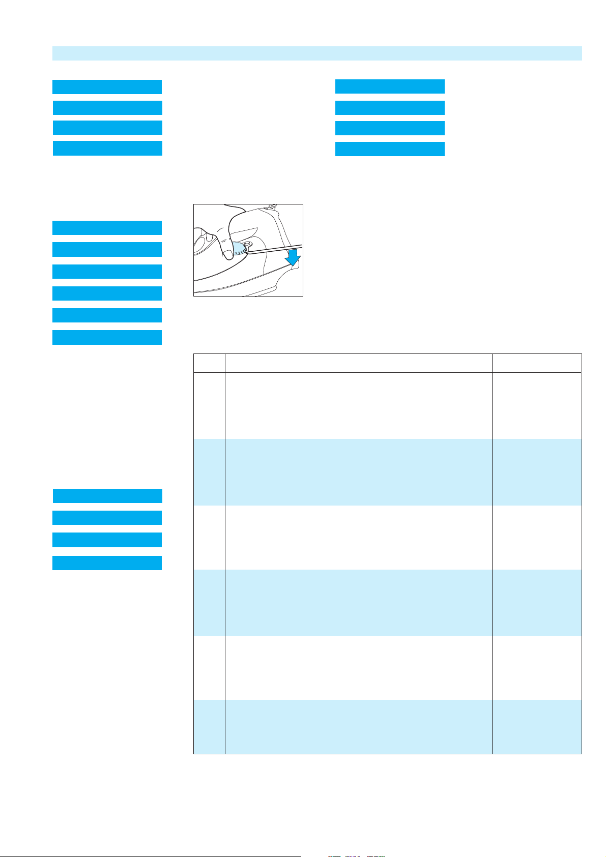
DISASSEMBLY ADVICE
1 BLACK PLATE
2 SWIVEL
3 CORD SET
7 CONTROL UNIT
remove screw A x1
remove black plate 1
remove screw B x2
cord clamping
4 OPERATION KNOB
5 DOSING UNIT
6 INLAY
7 CONTROL UNIT
8 PUMP
9 NOZZLE
remove screw A x1
remove black plate 1
remove screw B x2
cord clamping
remove cord set 3
remove dosing unit 5
remove screw D x1
remove operation knob 4
remove screw C x2
remove inlay 6
10 DIAL
11 LIGHT CONDUIT
12 TANK SET
13 LIGHT
remove screw A x1
remove black plate 1
remove dosing unit 5
remove screw D x1
remove operation knob 4
remove screw C x2
remove inlay 6
remove dial 10
remove screw E x1
14 COVER
15 THERMOSTAT BUSH
16 SOLEPLATE
17 SEALNG SET
remove screw A x1
remove black plate 1
remove dosing unit 5
remove screw D x1
remove operation knob 4
remove screw C x2
remove inlay 6
remove dial 10
remove screw E x1
remove tank set 12
remove screw F x3
remove cover 14
Item Description Consisting of Service code
1 Backplate 4822 441 12291
2 Swivel 4822 325 10229
3 Cord set EU 4822 321 11467
4 Operation knob HI312 (blue) 102 4239 026 01130
Operation knob HI322 (blue) 103, 104 9965 000 03236
Operation knob HI332/342 (green) 103, 104 4822 310 11282
5 Dosing unit HI312 4822 690 10199
Dosing unit HI322-342 4822 690 10201
6 Inlay HI312 (printed) 4239 020 94700
Inlay HI322 (printed) 4239 020 94880
Inlay HI332 (printed) 4239 020 94900
Inlay HI342 (printed) 4239 020 94180
Inlay HI322-342 (unprinted) 4239 026 01270
7 Control unit 100V-127V 4822 214 13002
Control 220V-240V 4822 214 13003
8 Pump 4822 360 10416
9 Nozzle 4822 479 20254
10 Dial 4822 410 12207
11 Light conduit 4822 530 10502
12 Tank set HI312 105 4822 418 10406
Tank set HI322 105 4822 418 10407
Tank set HI332/342 105 4822 418 10408
13 Lamp 4822 134 10124
14 Cover 4822 442 01674
15 Thermostat bush 4822 532 61258
16 Soleplate + thermostat 100V (coated) 4822 259 10313
Soleplate + thermostat 110-127V (coated) 4822 259 10314
Soleplate + thermostat 220-240V (coated) 4822 259 10315
17 Sealing set 106, 107 4822 310 11269
 Loading...