

Philips HI282 Service Manual
Philips Domestic Appliances and Personal Care
PRODUCT INFORMATION
Steam Iron
HI 282
HI 284
HI 292
HI 294
Features HI 282 HI 284 HI 292 HI 294
Pilot light xxxx
Integrated cord winder xxxx
Spray xxxx
Shot of steam xxxx
Self-clean xxxx
Length cord set 2.5 m xxxx
Anti-drip function xxxx
Automatic shut-off - - x x
Soleplate coated x - x Soleplate stainless steel - x - x
Voltage / frequency : 220 - 240 V, 50-60 Hz
110 - 127 V, 50-60 Hz
Power consumption : 220 - 240 V → 1325 Watts
110 - 127 V → 1200 Watts
Soleplate temperature with dial at max. position : 215 ± 25 °C
Self-clean function :
The self-clean function is operated by the steam dial. When
this dial is turned to the correct position, a sudden flow of
cold water is released from the tank into the heated
soleplate. This thermal shock will cause scale particles to
break loose from the steam chamber. These particles are
then flushed out through the steam vents by the water.
Auto shut-off :
A relay in the electronic module interrupts the power to the
heating element when the iron has been motionless in :
– for 30 seconds in horizontal position
– for 8 minutes in vertical position.
When the iron is moved again, it’s automatically switches
on again.
N.B. When the iron is plugged in in horizontal position, it
will not be switched off during the first 2 minutes to
ensure that it heats up properly.
Anti-drip :
Water is only released through the tank valve ( 101 ) into the
steam chamber if the sole plate temperature is high enough
to evaporate all water. lf the temperature is not hot enough
the tank valve is closed by means of the bi-metal disc ( 24 ).
This product meets the requirements regarding
interference suppression on radio and TV.
Published by Philips Domestic Appliances an d P ersonal Care Printed in the Netherlands
4822 729 21821
97/04
PCS 88 668
©
Copyright reserved Subject to modification
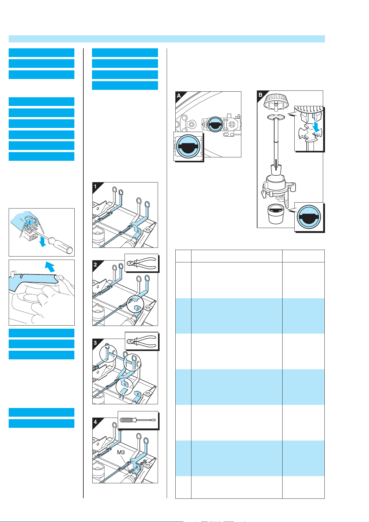
DISASSEMBLY ADVICE REASSEMBLY ADVICE + PARTS LIST
BACKPLATE 3
CORD SET 4
SWIVEL 5
remove SCREW A 2x
remove BACKPLATE 3
INLAY/LAMPCOVER 6
PILOT LIGHT 7
PCB 8
DIAL THERMOSTAT 9
RATTLE SPRING 11
DIAL LINK 12
turn DIAL 9 on max position
remove SCREW A 2x
remove BACKPLATE 3
remove SCREWS cordset/
pilot light
remove SCREW B lx
remove INLAY 6
COVER 18
TYPEPLATE 19
SOLEPLATE 21
THERMOSTAT 20
remove SCREW A 2x
remove BACKPLATE 3
remove SCREWS cordset/
pilot light/pcb
remove SCREW B lx
remove INLAY 6
remove SCREW 22
remove DIAL HOLDER 10
remove PUMP/SPRAY
UNIT 14
remove SCREW D 3x
Replacement Thermostat
see fig.1-4
REASSEMBLY ADVICE
When reassembling the iron, make sure that :
* Thermostat bush ( 17 ) is set to the position illustrated in fig A.
* Dial Link ( 12 ) and Dial Thermostat 9 are set to the
positions, illustrated in fig B.
DIAL HOLDER 10
SPRAY UNIT 13
PUMP/SPRAY UNIT 14
remove SCREW A 2x
remove BACKPLATE 3
remove SCREWS cordset/
pilot light
remove SCREW B lx
remove INLAY 6
remove SCREW 22
HANDLE 15
WATERTANK 16
remove SCREW A 2x
remove BACKPLATE 3
remove SCREWS cordset/
pilot light/pcb
remove SCREW B lx
remove INLAY 6
remove SCREW 22
remove DIAL HOLDER 10
remove PUMP/SPRAY
UNIT 14
remove SCREW C 2x
PCS 88 669
PARTS LIST
Pos Description
dosing unit
1
cord clip
2
cord winder/backplate
3
cord set Euro plug
4
cord set UK plug
cord set UL plug
cord set “China plug”
swivel
5
inlay + lampcover H1 282/284
6
inlay + lampcover H1 292/294
7
pilot light 220 - 240 V
pilot light 110 - 127 V
PCB auto shut off 220 - 240 V
8
PCB auto shut off 110 - 127 V
dial thermostat
9
dial holder + spring 11
10
rattle spring
11
dial link
12
spray unit
13
pump/spray unit incl. item 13 + 106
14
15
handle unprinted
16
tank + stopper 102/H1272 and sealing 103
17
thermostat bush
18
cover
19
type plate unprinted
2021thermostat
sole plate 220 - 240 V
incl. item 20 + 24 + 104
sole plate 110 - 127 V
incl. item 20 + 24 + 104
22
long tapping screw
23
kit sealings item 101 - 107
24
bi-metal disc 24 + tank valve 101
Service Code
4822 360 10142
4822 401 11193
4822 441 12002
4822 321 10951
4822 321 10952
4822 321 10947
4822 321 11317
4822 325 80505
4822 310 11004
4822 310 11005
4822 134 20334
4822 134 20335
4822 214 12293
4822 214 12294
4822 412 40262
4822 256 10379
4822 492 32876
4822 535 93498
4822 360 60291
4822 360 10321
4822 498 10657
4822 310 11006
4822 532 61258
4822 442 00973
4822 452 10337
4822 282 30229
4822 259 10264
4822 259 10265
4822 502 21315
4822 310 11007
4822 310 11008
 Loading...