

Philips HI 116, HI 114, HI 110, HI 108, HI 105 Service Manual
Philips Domestic Appliances and Personal Care
PRODUCT INFORMATION
Irons
HI 105
HI 108
HI 110
HI 114
HI 116
HI 105 HI 108 HI 110 HI 114 HI 116
colour white x x - x -
colour red - - x - x
sole plate linished x x x - -
sole plate coated - - - x x
pilot lamp - x x x x
Voltage / frequency : 220 - 240 V, 50 - 60 Hz
: 110 - 127 V, 50 - 60 Hz
Power consumption : 900 - 1100 Watts
Product meets the requirements regarding interference
suppression on radio and TV.
Published by P hilips Domestic Appliances and Personal Care Printed in the Netherlands
4822 729 21693
96/08
PCS 87 781
©
Copyright reserved Subject to modification
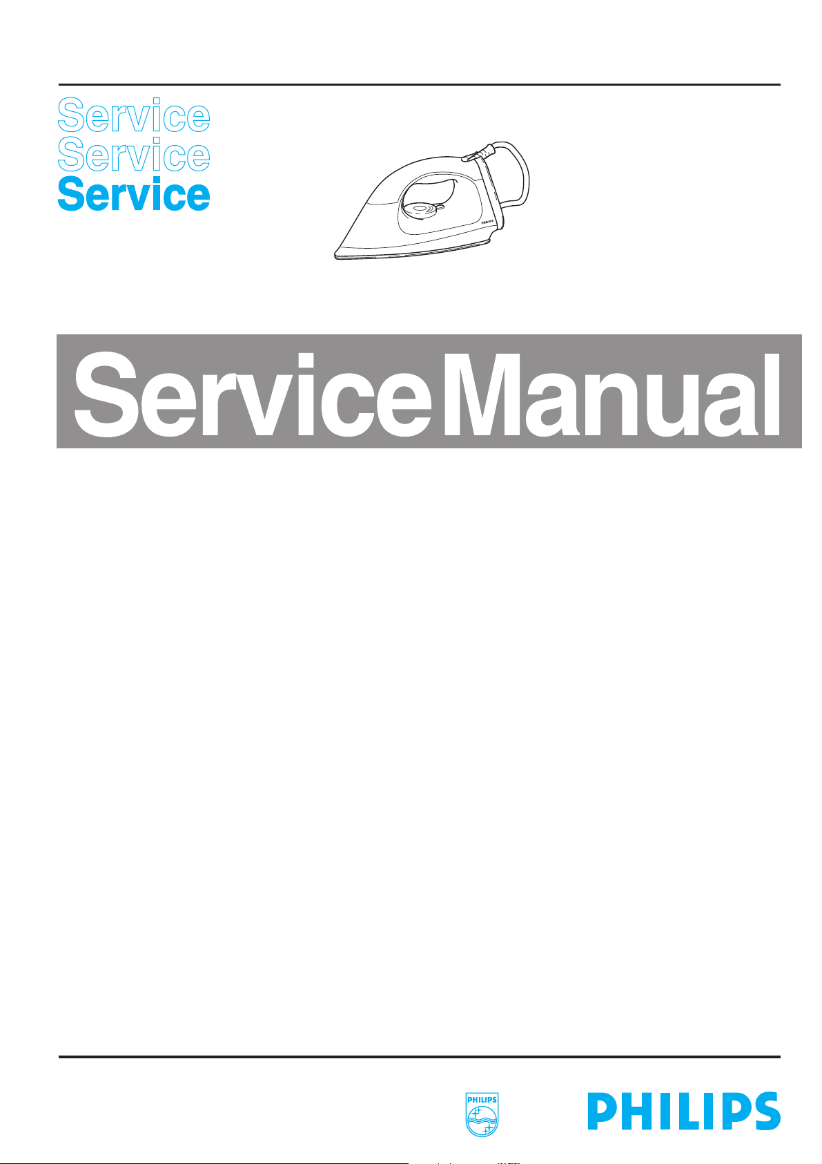
ASSEMBLY ADVICE PARTS LIST HI 105 / HI 108 / HI 110 / HI 114 / HI 116
CORDSET 5
remove SCREW A
remove BACK PLATE 101
remove SCREW A
remove BACK PLATE 101
remove SCREW B 3x
remove CORDSET 5
remove INLAY 103
SOLE PLATE 1
THERMOSTAT 3
INSOLATION
STUDS 3
LAMP 4
remove DIAL 102
NOTE:
After the product has been repaired, it should function
properly and has to meet the safety requirements and legal
regulations as laid down and officially established at this
moment.
remove SCREW C 3x
remove HANDLE 104
POS. DESCRIPTION SERVICE CODE
1 SOLE PLATE 110 - 127 V (incl. pos. 3) 4822 259 10209
1 SOLE PLATE 220 - 240 V (incl. pos. 3) 4822 259 10211
2 INSOLATION STUDS 4822 532 12722
3 THERMOSTAT 4822 282 10298
4 PILOT LAMP 100 - 240 V 4822 134 10055
5 CORDSET EURO PLUG 4822 321 10951
5 CORDSET UK PLUG 4822 321 10952
5 CORDSET UL PLUG 4822 321 10947
NOTES: For standarisation reasons:
only the coated sole plate will be supplied for those types,
*
which are suitable for 220 - 240 V.
only the linished sole plate will be supplied for those types,
*
which are suitable for 110 - 127 V.
only cordsets with a length of 2.6 m will be supplied.
*
the colour of the cordset may differ from the original
colour.
Parts, with numbers from 100 and higher, cannot be ordered
separately.
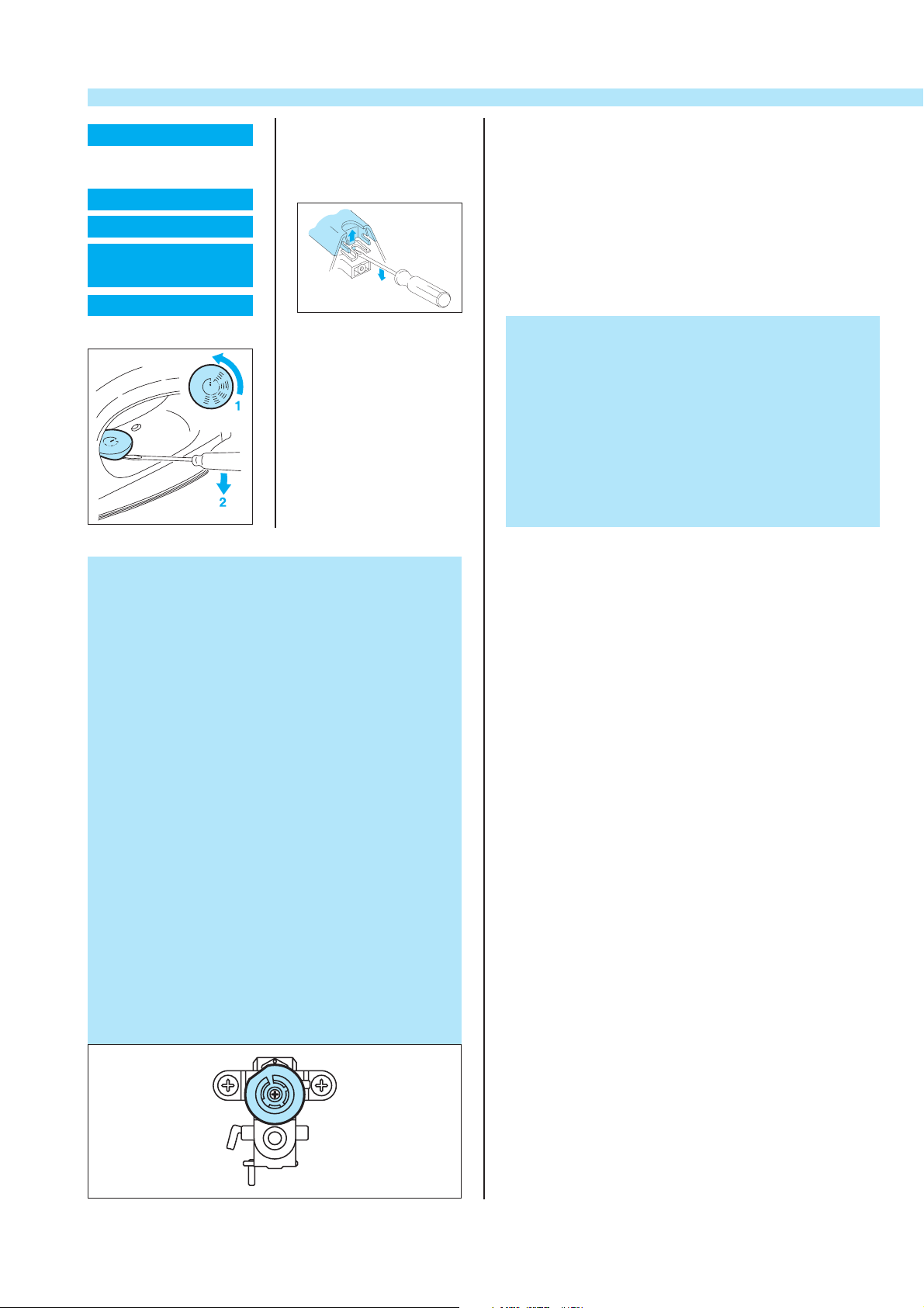
ADJUSTMENT AND CONTROLS
Thermostat 3
Thermostat ( 3 ), fitted to sole plate ( 1 ) has already been
adjusted by the supplier and secured by glue.
To avoid disfunction of the iron, NEVER readjust the
thermostat.
Adjustment Thermostat 3, supplied as a spare part.
Connect the connecting strips to an Ohm meter.
Set the vertical slot of the thermostat bush to the
11 o’clock position ( see picture ).
Turn the adjusting screw clockwise or anti-clockwise until
the Ohm meter indicates “0". ( the contacts are closed )
Then turn the adjusting screw clockwise until the Ohm
meter indicates ∞. ( the contacts are open )
While free turning the thermostat bush, check if the
thermostat switches in the 11 o’clock position.
Secure the adjusting screw by glue.
After adjusting the thermostat, always check the
temperature of the soleplate, with the dial set on the
MAX. position. ( 220 ± 20 °C )
 Loading...