

Page 1
POWER TO SAVE A LIFE
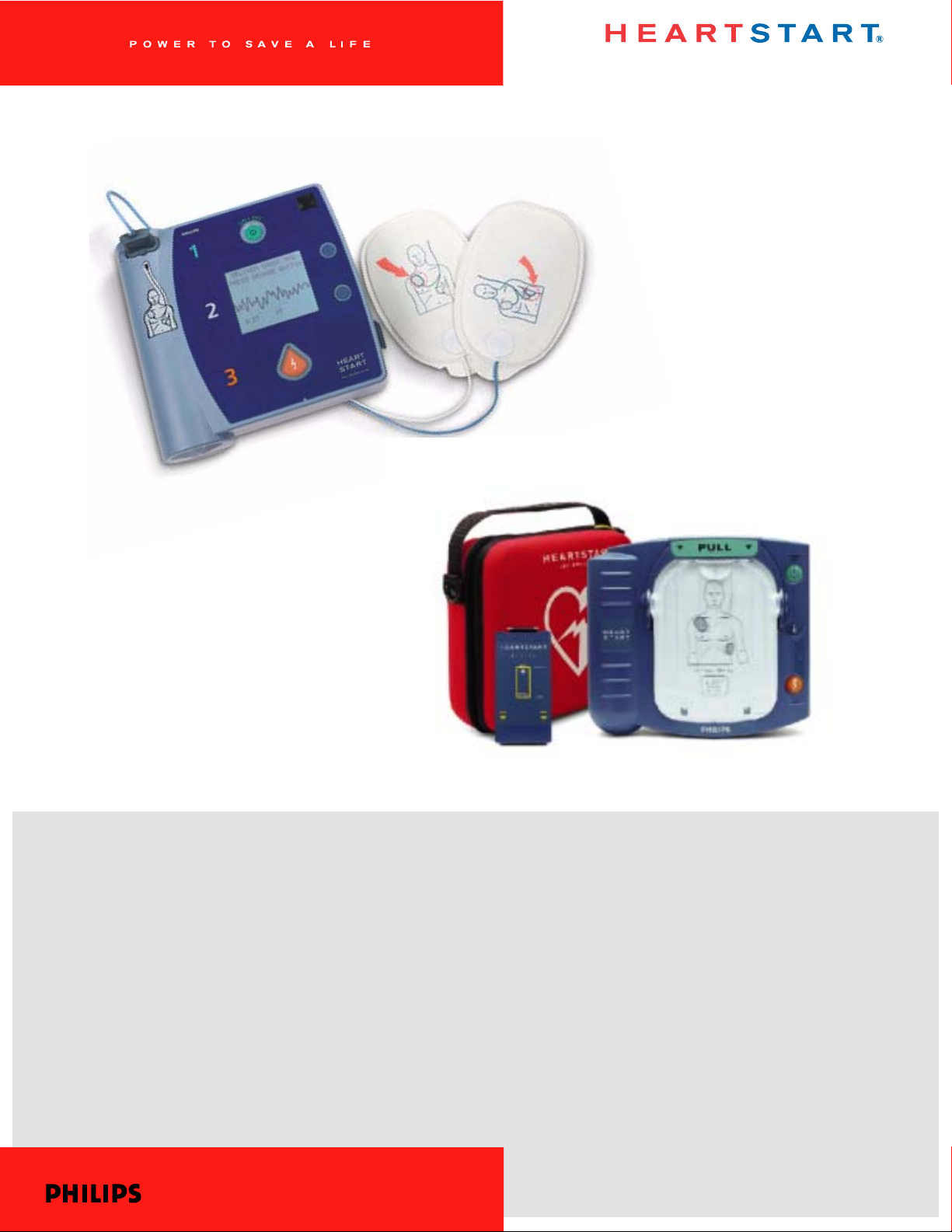
DEFIBRILLATORS
HEARTSTART
AUTOMATED EXTERNAL DEFIBRILLATORS
TECHNICAL REFERENCE MANUAL
Edition 3
Page 2

Introductory Note
In 1992, Heartstream, Inc. was founded with the mission to develop a small, low-cost,
rugged, reliable, safe, easy-to-use, and mainte nance-free automated external defibr il lator
(AED) that could be successfully used by a layperson responding to sudden cardiac arrest.
Heartstream introduc ed its first AED, the Fo reRunner, in 1996. The Heartstream ForeRunner
AED marked the first widespread commercial use of a biphasic waveform in an external
defibrillator.
Hewlett-Packard (HP) purchased Heartstream in 1997. Heartstream then added a relabeled
version of the ForeRun ner for Laerd al Medical Corporation called the Heartstart FR.
In 1999, Hewlett-Packard spun off the Medical Products Group, including the Heartstream
Operation, into Agilent Technologies. While part of Agilent, Heartstream introduced a new
AED, the Agilent Heartstream FR2. Laerdal Medical marketed this device as the Laerdal
Heartstart FR2.
Heartstream beca me part o f Ph ili ps Med ica l Sys t ems in 2001 when Philips purc hased the
entire Medical Group from Agilent Technologies. In 2002, Philips re-branded all of their
defibrillat ors as HeartStart Defibrillator s. In the same year, Philips introd uced a new family of
defibrillat ors, including the HeartStart Home and HeartStart OnSite AEDs.
This manual i s inten ded to p rovide technical and pr oduct infor mation t hat generally appli es to
the following AEDs:
ForeRunner and FR AEDs:
Heartstream ForeRunner Laerdal Heartstart FR
FR2 series AEDs:
Agilent Technologies FR2 Laerdal Heartstart FR2
Philips HeartStart FR2+ Laerdal Heartstart FR2+
HS1 family of AEDs:
Philips HeartStart OnSite Laerdal HeartStart
Philips HeartStart Ho me
To help simplify the information presen ted, the Hea rtStart FR2 is us ed as a n example in ma ny
parts of this manual. W here the discussion involv es features r elated to a speci fic product, it is
so noted.
Philips Medical Systems
Page 3

CONTENTS
1 HeartStart Automated External Defibrillators
Design Philosophy for H eartStart A EDs .............................. 1-1
Design Features of HeartStart AEDs .................................... 1-2
Reliability and Safety ...................................................... 1-2
Ease of Use ...................................................................... 1-3
No Maintenance .............................................................. 1-4
2 Defibrillation and Elect ricity
The Heart’s Electrical System ................................................. 2-1
Simplifying Electricity ................................................................ 2-4
3 SMART Biphasic Waveform
A Brief History of Defibrillation ............................................... 3-1
SMART Biphasic .............................................................. .......... 3-4
Understan d ing Fixed Energy ........................................ 3-5
Evidence-Based Support for the SMART
Biphasic Wave form ............................ .... .... ... .... .... .... ..... 3-6
SMART Biphasic Superior to Monophasic ............... 3-7
Key Studies ......................................................... ............. 3-8
Frequently Asked Questions ................................................... 3 -9
Are all biphasic waveforms alike? ............................... 3-9
How can the SMART Biphasic waveform be more
effective at lower energy? ............................................. 3-9
Is escalating energy required? ..................................... 3-11
Is there a relationship between waveform, energy
level, and po st-shock dysfunct ion? ............................. 3-13
How does SMART Biphasic compare to other
biphasic w a veforms? ..................................................... 3-15
Is there a standard for biphasic energy levels? ....... 3-15
Commitment to SMART Biphasic ...................... ......... 3-16
4SMART Analysis
Pad Contact Quality ............................................................ ...... 4-1
Artifact Detection ....................................................................... 4-1
Arrhythmia Detection ................................................................ 4-4
Philips Medical Systems
Shockable Rhythms ..................................... ............................. 4-6
Validation of Algorithm .............................................................. 4-9
ECG Analysis Performance .......................................... 4-9
i
Page 4

ii
5Self-Tests
Battery Insertion Test ................................................................ 5-1
ForeRunner and FR2 Series AED s ............................. 5-2
HeartStart HS1 Family of AEDs .. ................................ 5-2
Periodic Self-Tests ................ .................................................... 5-3
“Power On” and “In Use” Self-Tests .......................... 5-5
Cumulative Device Record ........................................... 5-6
Supplemental Maintenance Information for
Technical Professionals ........................... ................................. 5-7
Backgroun d .............................. ........................... ............. 5-7
Calibration requirements and intervals .............. ......... 5-7
Maintenance testing ....................................................... 5-7
Verification of energy discharge .................................. 5-7
Service/Maintenance and Repair Manual ............. ..... 5-7
6 Theory of Operation
Overview .................. ............................... ..................................... 6-1
User interface ........................................................ ..................... 6-3
Operation ... ........................... ........................... ................. 6-3
Maintenan ce .................. ................... ................... ............. 6-3
Troublesho ot in g .... ........ .... ... .... .... .... .... .... .... ....... .... .... .... . 6-3
Configuration ................................................................... 6-4
Control Bo ard ............................................................................. 6-4
Battery .......................................................................................... 6-4
Power Supply ............................................................................. 6-4
ECG Front End ... .... .... ........ .... .... ... .... .... .... .... .... ....... .... .... .... .... .. 6-5
Patient Circuit ............................................................................. 6-5
Recording .................................................................................... 6-5
Temperatu re Sensor ............................................................... .. 6-6
Real-Time Clock ............. ............................................................ 6-6
IR Port ......................................................................... .................. 6-6
TECHNIC AL REFERENCE GU ID E
Philips Medical Systems
Page 5

7 Literature Summary for HeartStart
AEDs
References .................................................................................. 7-1
Animal Studies (peer-reviewed manuscripts) ........... 7-1
Electrophysiology Laboratory and other studies
(peer-reviewed manuscripts) ........................................ 7-2
Sudden Cardiac Arrest
(peer-reviewed manuscripts) ........................................ 7-3
Animal Stu dies (abstracts) ............................................ 7-4
Out-of-H ospital Study (abstract) ................................. 7-4
Related Papers and Publications ................................ 7-4
Study Sum maries .......................................... ............................. 7-6
HeartStart Defibrillation Therapy Testing in Adult
Victims of Out-of-Hospital Cardiac Arrest ................ 7-6
HeartStart Patient Analysis System Testing with
Pediatric Rhythms ........................................................... 7-8
HeartStart Defibrillation Therapy Testing in a Pediatric
Animal Model ................................... ................................ 7-10
iii
8 Condensed Applicati on Notes
Defibrillation on Wet or Metal Surfaces ............................... 8-2
Defibrillating in the Presence of Oxygen ................ .............. 8-2
Value of an ECG Display on HeartStart AE Ds ................... 8-3
Defibrillation Pad Placement with HeartStart
AEDs .......... ............... ................ ............... ................ ............... ...... 8-4
SMART Analysis - Classification of Rh ythms ...................... 8-5
Artifact Detection in HeartStart AEDs .................................. 8-6
Use of Automated External Defibrillators (AEDs)
in Hospitals ..................................................... ............................. 8-7
Manual Mode of Operation with HeartStart
AEDs ........... ........................... ........................... ................. 8-7
Analysis System in Hear tStart AEDs .......................... 8-8
Shockable/Non-Sho ckable Rhythms .......................... 8-9
Defibrillation Electrode Pads for HeartStart
AEDs ........... ........................... ........................... ................. 8-10
CPR Performed at High Rates of Compressio n ...... 8-10
HeartStart A ED Batte ry Safety ..................................... ..........8-11
Philips Medical Systems
Differences in Battery Chemistries Utilized by
Automated External Defibrillators ............ ... .... ........ .... . 8 -11
Additional Advantages of the HeartStart AEDs
Battery: D isposable vs. Rechargeable ....................... 8-12
Contents
Page 6

iv
9 Technical Specificat ions
Standards Applied ............................................................... ...... 9-1
AED Specifications ................................................................... 9-2
Physical ............................................................................. 9-2
Environme ntal ........ .... .... .... ... .... .... .... .... ........ ... .... .... .... .... . 9-3
AED (Hea rtStart HS1 Family) ...................................... 9-4
ECG Analysis System .................................................... 9-5
Display ............................................... ............................... . 9-6
Controls and Indicators ............................. .................... 9-7
Data Management Sp ecificatio ns ............................... 9-8
Accessor ies Speci fic a tions ..................................................... 9-9
Battery Packs ................................................................... 9-9
HeartStart Defibrillation Pads .............. ........................ 9-9
10 Features of th e ForeRunner , FR2,
and HS1 AEDs
Overview .................. ............................... .....................................10-1
Feature Comparison .............. ............... .....................................10-2
Voice Prompt Co mpa r ison ................. .... .... .... .... ... .... .... .... ...... 10 -3
Additional HS1 Voice Instructions ............................. . 10-5
AED Trainers .................................. ............................................. 10-6
Training Scenarios .................. ........................................ 10-7
Pediatric Pads ............................ ................................................10-8
11 HeartStart D ata Manag ement S oftware
Appendix
TECHNIC AL REFERENCE GU ID E
Comparison of Event Review Pro 2.3 and
Event Review 3.0 .......................................................................11-2
System Requirements ...............................................................11-3
Operating Systems ......................................................... 11-3
Data Card Readers .......... ............... ................................ 11-4
Previous Data Management Software Versions .................11-5
System An notations ..................................................................11-6
Technical Support for Data Man a gement Software ..........11-8
Online ................................................................................ 11-8
Via Telephone .................................................................. 11-8
Philips Medical Systems
Troubleshooting the HeartStart the ForeRunner and
FR2 Series AEDs ....................................................................... A-1
Page 7

1 HeartStart Automated External
Defibrillators
Each year in the United States alone, approximately 250,000 people suffer
sudden cardiac arrest (SCA). Fewer than 5% of them survive. SCA is most
often caused by an irregu lar hear t rhyth m called ventr icula r fibrill ation (VF), for
which the only eff ective t reatme nt is de fibr illati on, an electr ical shoc k . Of ten, a
victim of SCA does not survive because of the time it takes to deliver the
defibrillation shock; for every minute of VF, the chances of survival decrease
by about 10%.
T raditi onally , on ly trained medical personne l were allow ed to use a de fibrillat or
because of the high level of knowledge and training involved. Initially, this
meant that the victim of SCA would have to be transported to a medical
facility in order to be defi brillated. In 19 69, par ame di c pr ograms were
developed in several communities in the U.S. to act as an extension of the
hospital emergency room. Paramedics went through extensive training to
learn how to deliver emergency medical care outs id e the hos pi tal, including
training in defibrillation. In the early 1980s, some Emergency Medical
Technicians (EMTs) were also being trained to use defibrillators to treat
victims of SCA. However, even with these adva nces , in 1990 fewer than half
of the ambulances in the United States carried a defibrillator, so the chances
of surviving SCA outside the hospital or in communities without highly
developed Emergency Medical Systems were still very small.
1
The development of the automated external defibrillator (AED) made it
possible for a defibrillator to be used by the first people (typically lay persons)
responding to an emergency. People trained to perform CPR can now use a
defibrillator to defibrillate a victim of SCA. The result: victims of sudden
cardiac arrest can be defibrillated more r apidly than ever be fore , an d t hey
have a better chance of su rviving until more highly trained medical personnel
arrive who can treat the underlying causes .
Design Ph iloso phy for HeartStart AED s
The HeartStart AEDs are designed specifically to be used by the first people
responding to an emergency. It is reliable, easy to use, and virtual ly
maintenance free. The design allows HeartStart AEDs to be used by people
with no medical training in places where defibrillators have not traditionally
Philips Medical Systems
been used. In order to accomplish this, consideration was given to the fact
that an AED might not be used very often, may be subjected to harsh
environments, and probably would not have personnel available to perform
regular maintenance.
1-1
Page 8

1-2
The HeartStart AED was not designed to replace the manual defibrillators
used by more highly trained individuals. Instead, it was intended to
complement the efforts of medical personnel by allowing the initial shock to
be delivered by the first person to arrive at the scene. Some models of
HeartStart AEDs can be configured for advanced mode use, to allow the
device to be used as a manual defibrill ator. This can be beneficia l for
transitioning the p atient care from a lay rescue r to more highly t rained medical
personnel.
Design Features of HeartStart AEDs
Reliability and Safety
• Fail-Safe Design - The HeartStart AED is intended to detect a
shockable rhythm and deliver a shock if needed . It will not allow a shoc k if
one is no t required.
•
Rugged Mechanical Design - The HeartStart AED is built with
high-impact plastics, has few openings, and incorporates a rugged
defibrillation pads connector and bat tery inter f ace. Using the carry case
provides additional protection as well as storage for extra sets of pads
and a spare batt e r y.
Daily Automatic Self-Test - The HeartStart AED performs a daily
•
self-test to help ensure it is ready to use when needed. An active status
indicator demonstrates at a glance that the unit is working and ready to
use.
•
Environmental Parameters - Ex tensive environmental tests were
conducted to prove the HeartStart AED’s reliability and ability to operate
in conditions relevant to expected use.
•
Non-Rechargeable Lith ium Batte ry - The HeartStart AED
battery pack was design ed for us e in an emer gen cy environment and is
therefore small, lightweight, and safe to use. Each battery pack contains
multiple 2/3A size, standard lithium camera batteries. These same
batteries can be purc has ed at lo cal drug st ores for use in other consumer
products. These batteries have been proven to be reliable and safe over
many years of operation. The HeartStart AED battery pack uses lithium
manganese diox id e (L i/MnO
) technology and does not contain
2
pressurized sulfur dio xid e. T he battery pac k meets the U.S. Environme ntal
Protection Agency's Toxicity Characteristic Leaching Procedure and may
be disposed of with normal waste.
Philips Medical Systems
TECHNICAL REFERENCE GUIDE
Page 9
1-3
Ease of Use
• Small and Light - The b ip has ic waveform technology used in the
HeartStart AEDs have allowed them to be small and light. They can easily
be carried and operated by one person.
•
Self-Contained - The carr y case ha s room for ex tra defibrilla tion pa ds
and an extra battery. When stored in the carrying case, the AED has
everything necessary for a person to respond to an event of SCA.
•
Voice Prompts - The HeartStart AED provides audible prompts that
guide the user through the process of using the device. The prompts
reinforce the messages that appear on the AED screen (F R 2 series
models) and allow the user to attend to the patient while receiving
detailed instructions for each step of the rescue.
• Pads Connector Light and Flashing Shock Button - The
indicator light next to the pads connector port on the FR2 series AED
draws the user's attention to where the pads connector should be
plugged in. The HS1 famil y of AEDs uses a pads c art ri dge t hat is
connected as soon as it is installed in the AED. The illuminated Shock
button identifies the button to be pushed to deliver a shock; the Shock
button only flashes w hen the unit has char g ed for a s hock and directs the
user to press the orange shock button.
1
Clear Labeling and
•
Graphics
- The HeartStart AED
is designed to enable fast response
by the user. The 1-2-3 operation
guides the user to: 1) turn the unit
on, 2) follow the prompts, and 3)
deliver a shock if instructed. The
Quick Reference Card mounted
inside the carrying case reinforces
these instructions. The pad
placement icon on the FR2 series
AED indicates clearly where pads
should be placed, an d t h e pads
themselves are labele d to specify
where each one should be placed. T he polarity of the pads does not
affect the operation of the HeartStart AED, but user testing has shown
that people apply the pads more quickly and accurately if a specific
Philips Medical Systems
position is shown on each pad.
LCD Screen (on the FR2+) - The text screen displays message
•
prompts to remind the user what steps to follow during an incident. On
some HeartStart AED models, the screen also displays the vict im’s ECG
signal. The ECG helps ALS providers when they arrive on the scene, by
Introduction to the HeartStart D efibrillators
Page 10

1-4
enabling them to rapidly assess the patient's heart rhythm to prioritize
their initial care of the patient.
•
Proven Analysis System - The rhythm analysis system is the
decision-maker insi de the AED that analyzes the patient’s ECG rhythm
and determines whether or not a shock sh ould be administered. The
algorithm’s decision criteria allow the user to be confident that the AED
will only advise a shock when it is appropriate treatment for the patient.
Artifact Detection System - The AED’s artifact detection system
•
indicates if the ECG has been corrupted by some forms of art ifa ct fr om
electrical “noise” in the surrounding environment, patient handling, or the
activity of an implanted pacemaker. Because such artifact might inhibit or
delay the AED from making a shock decision, the AED compensates by
filtering out the noise from the ECG, prompting the user to stop patient
handling, or det er mining that the level of artifact does not pose a p r obl em
for the algorithm.
Pads Detection System - The HeartStart AED’s pads detection
•
system helps ensure good defibrillation pad contact by providing a voice
prompt to the user if the pads are not making proper contact with the
patient's skin.
No Maintenance
Unlike manual defibr illators (used in a hospi tal or by ALS providers)
automated external defib r illators may be used infreque ntly, possibly less than
once a year. However, they must be ready to use when needed.
•
Automatic Daily/Weekly/Monthly Self-tests - There is no
need for calibration, energy verification, or manual testing with the
HeartStart AED. Calibration and energy ver if ication are automatically performed once a month as part of the AED’s self-test routine.
•
Active Status Indicator - The HeartStart AED’s status indicator
shows whether or not the AED has passed its last self-test. The FR2+ is
ready to use when the indi cator is a flashing bla ck hourglass. If the status
indicator displ ays a flashing red X accompanied by an audible beep, this
means the AED needs attention. A soli d red X means tha t the AED cannot
be used. For the HS1, a flashing green lig ht ind ica tes that it is ready to
use.
Non-rechargeable Lit hium Battery - Non-rechargeable
•
batteries store more energy in the same size package , have a longer shelf
life than recha rgea b le ba tteries, and eliminate the need to manage and
maintain a recharging process. The HeartStart AED prompts the user via
the Status Indicator and an audibl e alarm when the battery needs to be
replaced.
Philips Medical Systems
TECHNICAL REFERENCE GUIDE
Page 11
2 Defibrillation and Electricity
The Heart’s Electrical System
The heart muscle, or myocardium, is a mass of muscle cells. Some of these
cells (“working” cells) are specialized for contracting, which causes the
pumping action of the heart. Other cells (“electrical system” cells) are
specialized for conduction. They conduct the electrical impulses throughout
the heart and allow it to pump in an organized and productive manner. All of
the electrical activity in the heart is initiated in specialized muscle cells called
“pacemaker” cells, which spontaneously initiate electrical impulses that are
conducted through pathways in the heart made up of electrical system cells.
Although autonomic nerves surround the heart and can influence the rate or
strength of the heart’s contractions, it is the pacemaker cells, and not the
autonomic nerves, that initiate the electrical impulses that cause the heart to
contract.
2
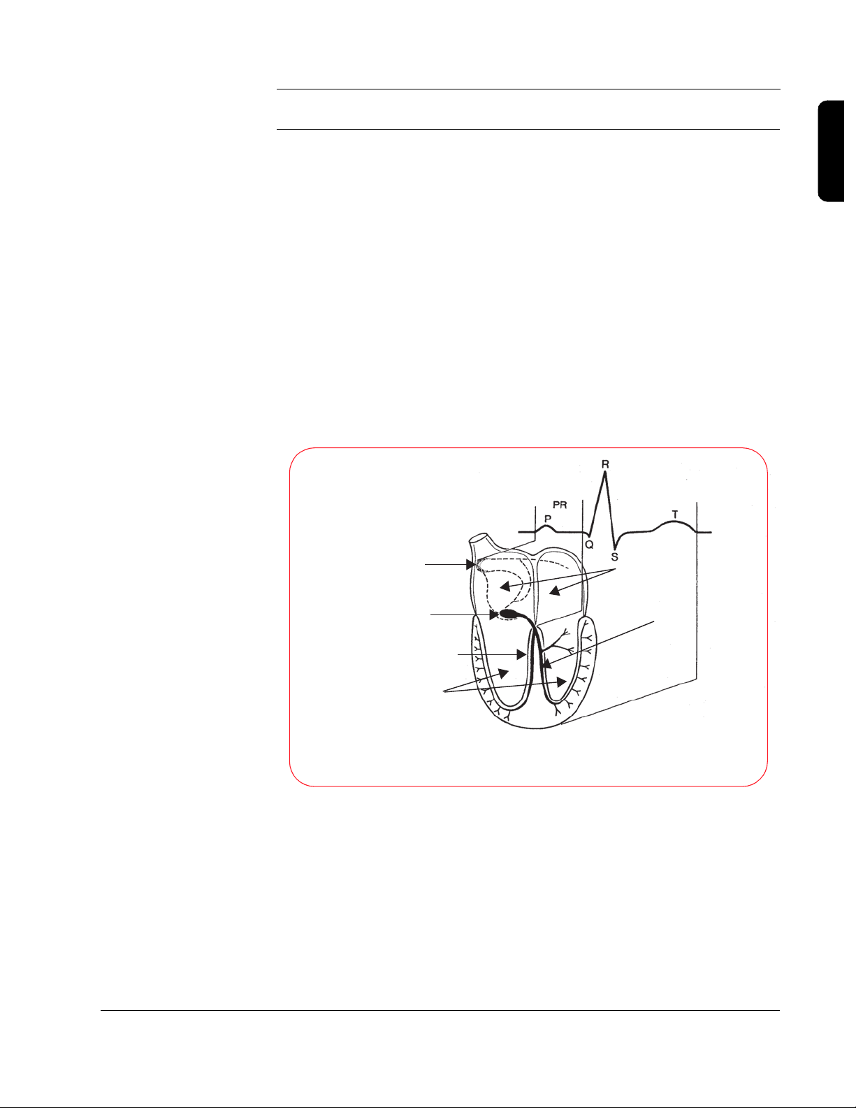
Sinus Node
(primary pacemaker cells
are located here)
A-V Node
Right Bundle Branch
Ventricles
Relation of an ECG to the
Anatomy of the Cardiac Conduction System
Atria
Left Bundle Branch
The heart is made up of four chambers, two smaller, upper chambers called
the atria, and two larger, lower chambers called the ventricles. The right atrium
collects blood returning from the body and pumps it into the right ventricle.
The right ventricle then pumps that blood into the lungs to be oxygenated. The
Philips Medical Systems
left atrium collects the blood coming back from the lungs and pumps it into
the left ventricle. Finally, the left ventricle pumps the oxygenated blood to the
body, and the cycle starts over again.
2-1
Page 12
2-2
2
1
0
-1
-2
The electrocardiogram (ECG) measures the heart's electrical activity by
monitoring the small signals from the heart that are conducted to the surface
of the patient’s chest. The ECG indicates whether or not the heart is
conducting the electrical impulses properly, which results in pumping blood
throughout the body. In a healthy heart, the electrical impulse begins at the
sinus node, travels down (propagates) to the A-V node, causing the atria to
contract, and then travels down the left and right bundle branches before
spreading out across the ventricles, causing them to contract in unison.
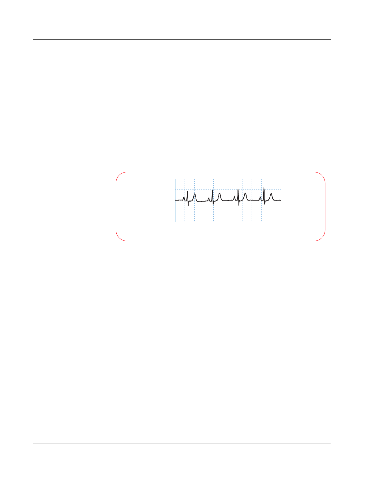
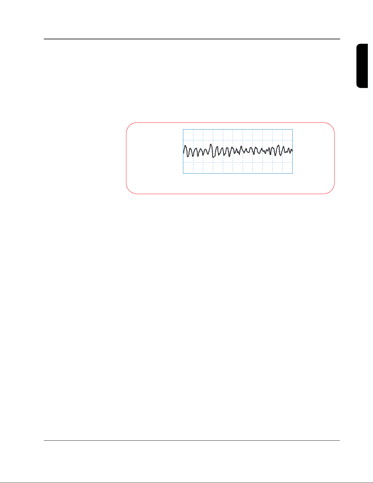
The “normal sinus rhythm” or NSR (so called because the impulse starts at
the sinus node and follows the normal conduction path) shown below is an
example of what the ECG for a healthy heart looks like.
Normal Sinus Rhythm
Millivolts
0 0.4 0.8 1.2 1.6 2.0 2.4 2.8 3.2 3.6 4.0 4.4
Seconds
Sudden cardiac arrest (SCA) occurs when the heart stops beating in an
organized manner and is unable to pump blood throughout the body. A
person stricken with SCA will lose consciousness and stop breathing within a
matter of seconds. SCA is a disorder of the heart’s electrical conduction
pathway that prevents the heart from contracting in a manner that will
effectively pump the blood.
Although the terms “heart attack” and “sudden cardiac arrest” are sometimes
used interchangeably, they are actually two distinct and different conditions. A
heart attack, or myocardial infarction (MI), refers to a physical disorder where
blood flow is restricted to a certain area of the heart. This can be caused by a
coronary artery that is obstructed with plaque and results in an area of tissue
that doesn't receive any oxygen. This will eventually cause those cells to die if
nothing is done. A heart attack is typically accompanied by pain, shortness of
breath, and other symptoms, and is usually treated with drugs or angioplasty.
Although sudden death is possible, it does not always occur. Many times, a
heart attack will lead to SCA, which does lead to sudden death if no action is
taken.
Philips Medical Systems
The most common heart rhythm in SCA is ventricular fibrillation (VF). VF refers
to a condition that can develop when the working cells stop responding to the
electrical system in the heart and start contracting randomly on their own.
TECHNICAL REFERENCE GUIDE
Page 13
2-3
2
1
0
-1
-2
When this occurs, the heart becomes a quivering mass of muscle and loses
its ability to pump blood through the body. The heart “stops beating”, and the
person will lose consciousness and stop breathing within seconds. If
defibrillation is not successfully performed to return the heart to a productive
rhythm, the person will die within minutes. The ECG below depicts ventricular
fibrillation.
Ventricular Fibrillation
Millivolts
0 0.4 0.8 1.2 1.6 2.0 2. 4 2.8 3.2 3.6 4.0 4.4
Seconds
Cardiopulmonary resuscitation, or CPR, allows some oxygen to be delivered
to the various body organs (including the heart), but at a much-reduced rate.
CPR will not stop fibrillation. However, because it allows some oxygen to be
supplied to the heart tissue, CPR extends the length of time during which
defibrillation is still possible. Even with CPR, a fibrillating heart rhythm will
eventually degenerate into asystole, or “flatline,” which is the absence of any
electrical activity. If this happens, the patient has almost no chance of survival.
2
Defibrillation is the use of an electrical shock to stop fibrillation and allow the
heart to return to a regular, productive rhythm that leads to pumping action.
The shock is intended to cause the majority of the working cells to contract
(or “depolarize”) simultaneously. This allows them to start responding to the
natural electrical system in the heart and begin beating in an organized
manner again. The chance of survival decreases by about 10% for every
minute the heart remains in fibrillation, so defibrillating someone as quickly as
possible is vital to survival.
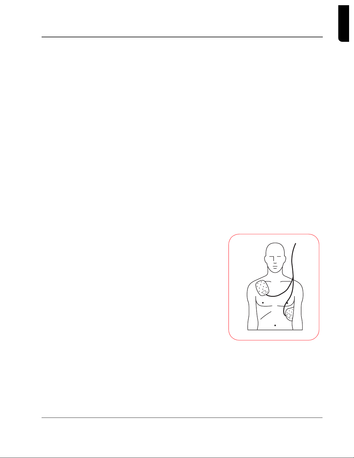
An electrical shock is delivered by a defibrillator, and involves placing two
electrodes on a person's chest in such a way that an electrical current travels
from one pad to the other, passing through the heart muscle along the way.
Since the electrodes typically are placed on the patient's chest, the current
must pass through the skin, chest muscles, ribs, and organs in the area of the
Philips Medical Systems
chest cavity, in addition to the heart. A person will sometimes “jump” when a
shock is delivered, because the same current that causes all the working cells
in the heart to contract can also cause the muscles in the chest to contract.
Defibrillation and Electricity
Page 14

2-4
Simplifying Electricity
Energy is defined as the capacity to do work, and electrical energy can be
used for many purposes. It can drive motors used in many common household
appliances, it can heat a home, or it can restart a heart. The electrical energy
used in any of these situations depends on the level of the voltage applied,
how much current is flowing, and for what period of time that current flows.
The voltage level and the amount of current that flows are related by
impedance, which is basically defined as the resistance to the flow of current.
If you think of voltage as water pressure and current as the flow of water out
of a hose, then impedance is determined by the size of the hose. If you have a
small garden hose, the impedance would be relatively large and would not
allow much water to flow through the hose. If, on the other hand, you have a
fire hose, the impedance would be lower, and much more water could flow
through the hose given the same pressure. The volume of water that comes
out of the hose depends on the pressure, the size of the hose, and the amount
of time the water flows. A garden hose at a certain pressure for a short period
of time works well for watering your garden, but if you used a fire hose with
the same pressure and time, you could easily wash your garden away.
*
Electrical energy is similar. The amount of energy delivered depends on the
voltage, the current, and the duration of its application. If a certain voltage is
present across the defibrillator pads attached to a patient's chest, the amount
of current that will flow through the patient's chest is determined by the
impedance of the body tissue. The amount of energy delivered to the patient
is determined by how long that current flows at that level of voltage.
In the case of the biphasic waveforms shown in the following pages, energy
E) is the power (P) delivered over a specified time (t), or E = P x t.
(
Electrical power is defined as the voltage (V) times the current
(volts= joules/coulomb, amps = coulombs/sec):
From Ohm's law, voltage and current are related by resistance (R)
(impedance):
Power is therefore related to voltage and resistance by:
Substituting this back into the equation for energy means that the
energy delivered by the biphasic waveform is represented by:
* Voltage is measured in volts, current is measured in amperes (amps), and impedance is measured in
ohms. Large amounts of electrical energy are measured in kilowatt-hours, as seen on your electric bill.
Small amounts can be measured in joules (J), which are watt-seconds.
P = V x I
V = I x R or
I = V/R
P = V2/R or
E = V2/R x t or
P = I
E = I
2
2
R x t
R
Philips Medical Systems
TECHNICAL REFERENCE GUIDE
Page 15
2-5
In determining how effective the energy is at converting a heart in fibrillation,
how the energy is delivered -- or the shape of the waveform (the value of the
voltage over time) -- is actually more important than the amount of energy
delivered.
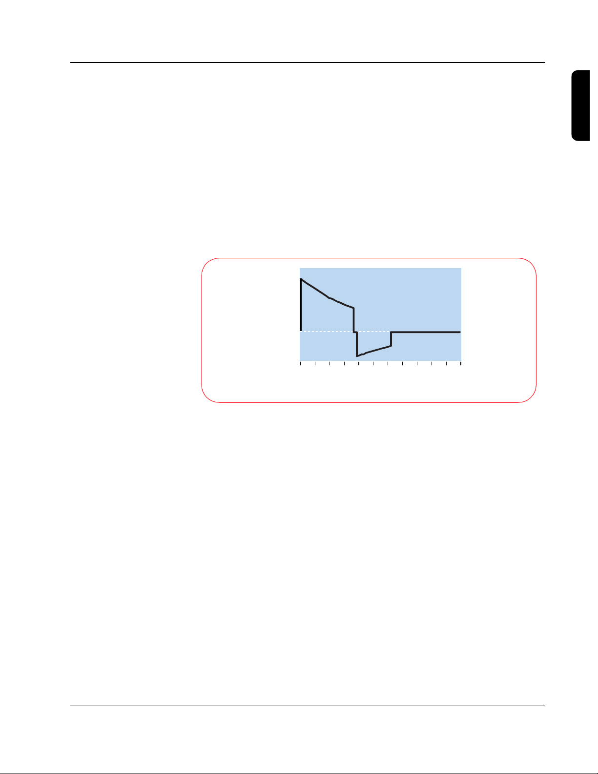
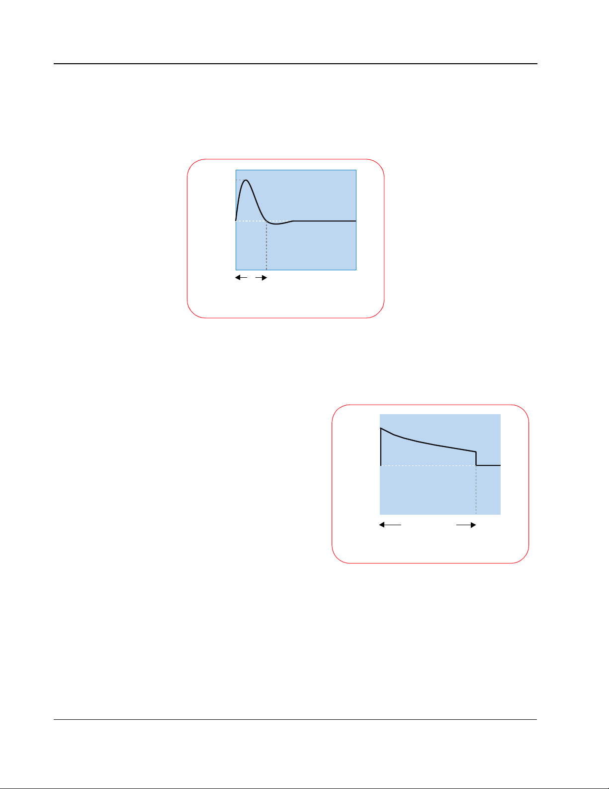
For the SMART Biphasic waveform, the design strategy involved starting with
a set peak voltage stored on the capacitor that will decay exponentially as
current is delivered to the patient. The SMART Biphasic waveform shown
here is displayed with the voltage plotted versus time, for a patient with an
impedance of 75 ohms. By changing the time duration of the positive and
negative pulses, the energy delivered to the patient can be controlled.
1500
1000
500
Volts
0
-500
2
0 2 4 6 8 10 12 14 1 6 18 20 22
Milliseconds
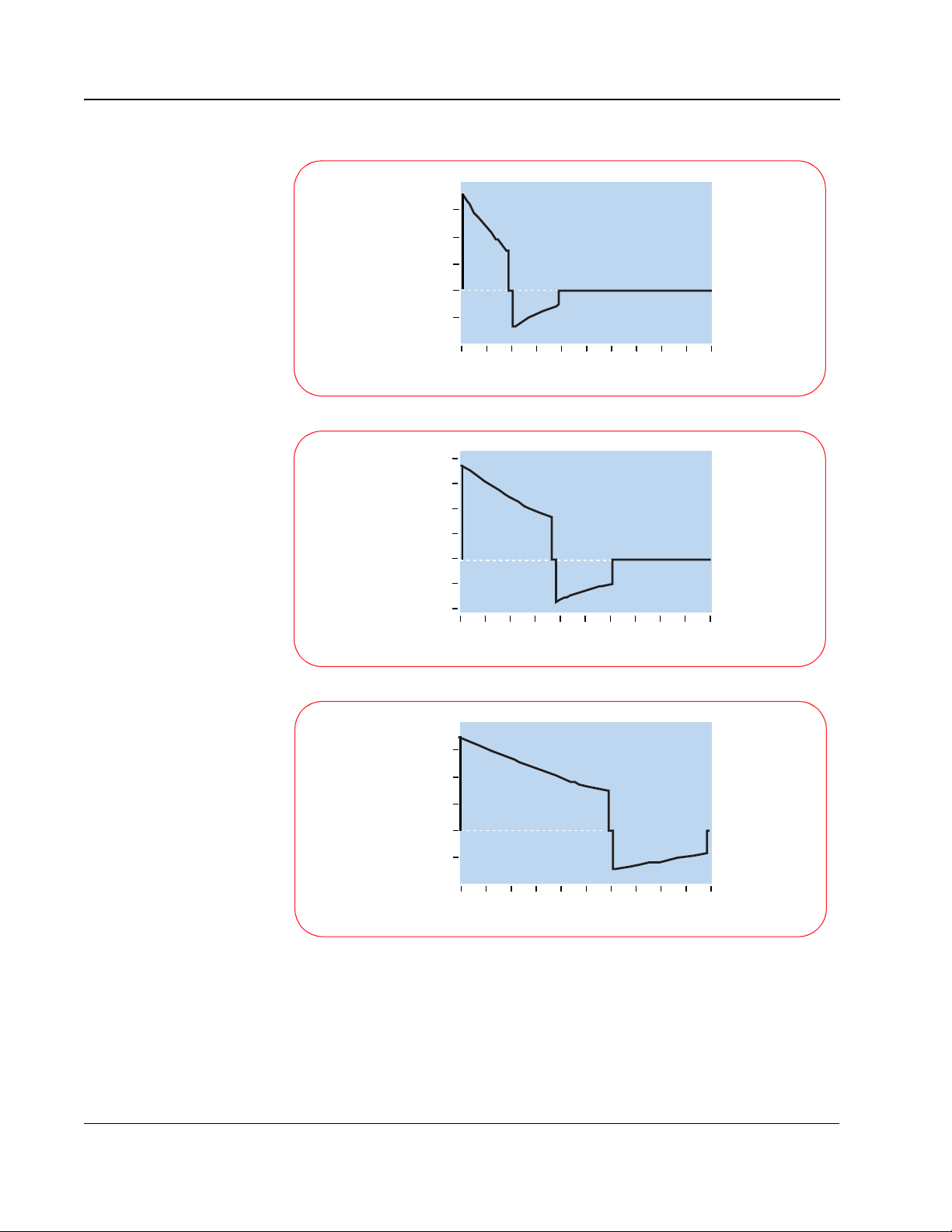
Although the relationship of voltage and energy is of interest in designing the
defibrillator, it is actually the current that is responsible for defibrillating the
heart. The three graphs shown here demonstrate how the shape of
the current waveform changes with different patient impedances. Once again,
the SMART Biphasic waveform delivers the same amount of energy
(150 J) to every patient, but the shape of the waveform changes to provide
the highest level of effectiveness for defibrillating the patient at each
impedance value.
Philips Medical Systems
Defibrillation and Electricity
Page 16
2-6
30
20
10
0
Amperes
-10
0 2 4 6 8 10 12 14 16 18 20
50 ohm patient
Milliseconds
25
20
15
10
0
Amperes
-5
80 ohm patient
-10
0 2 4 6 8 10 12 14 16 18 20
Milliseconds
30
20
10
0
Amperes
-10
0 2 4 6 8 10 12 14 16 18 20
125 ohm patient
Milliseconds
With the SMART Biphasic waveform, the shape of the waveform is optimized
for each patient. The initial voltage remains the same, but the peak current will
depend on the patient’s impedance. The tilt (slope) and the time duration are
adjusted for different patient impedances to maintain 150 J for each shock.
The phase ratio, or the relative amount of time the waveform spends in the
Philips Medical Systems
TECHNICAL REFERENCE GUIDE
Page 17

2-7
positive pulse versus the negative pulse, is also adjusted depending upon the
patient impedance to insure the waveform remains effective for all patients.
Adjusting these parameters makes it easier to control the accuracy of the
energy delivered since they are proportionally related to energy, whereas
voltage is exponentially related to energy.
The HeartStart Defibrillator measures the patient's impedance during each
shock. The delivered energy is controlled by using the impedance value to
determine what tilt and time period are required to deliver 150 J.
The average impedance in adults is 75 ohms, but it can vary from 25 to 180
ohms. Because a HeartStart Defibrillator measures the impedance and
adjusts the shape of the waveform accordingly, it delivers 150 J of energy to
the patient every time the shock button is pressed. Controlling the amount of
energy delivered allows the defibrillator to deliver enough energy to defibrillate
the heart, but not more. Numerous studies have demonstrated that the
waveform used by HeartStart Defibrillator is more effective in defibrillating
out-of-hospital cardiac arrest patients than the waveforms used by
conventional defibrillators. Moreover, the lower energy delivered results in less
post-shock dysfunction of the heart, resulting in better outcomes for survivors.
2
Philips Medical Systems
Defibrillation and Electricity
Page 18

Notes
TECHNICAL REFERENCE GUIDE
Philips Medical Systems
Page 19
3 SMART Biphasic Waveform
Defibrillation is the only effective treatment for ventricular fibrillation, the most
common cause of sudden cardiac arrest (SCA). The defibrillation waveform
used by a defibrillator determines how energy is delivered to a patient and
defines the relationship between the voltage, current, and patient impedance
over time. The defibrillator waveform used is critical for defibrillation efficacy
and patient outcome.
A Brief History of Defibrillation
The concept of electrical
defibrillation was introduced
over a century ago. Early
experimental defibrillators
used 60 cycle alternating
current (AC) household
power with step-up
transformers to increase the
voltage. The shock was
delivered directly to the heart
muscle. Transthoracic
(through the chest wall)
defibrillation was first used in
the 1950s.
2000
0
Volts
17
Milliseconds
Alternating Current (AC) Waveform
3
The desire for portability led to the development of battery-powered direct
current (DC) defibrillators in the 1950s. At that time it was also discovered
that DC shocks were more effective than AC shocks. The first “portable”
defibrillator was developed at Johns Hopkins University. It used a biphasic
waveform to deliver 100 joules (J) over 14 milliseconds. The unit weighed 50
pounds with accessories (at a time when standard defibrillators typically
weighed more than 250 pounds) and was briefly commercialized for use in
the electric utility industry.
Defibrillation therapy gradually gained acceptance over the next two decades.
An automated external defibrillator (AED) was introduced in the mid-1970s,
shortly before the first automatic internal cardioverterdefibrillator (AICD) was implanted in a human.
Philips Medical Systems
3-1
Page 20
3-2
During the last 30 years, defibrillators used one of two types of monophasic
waveforms: monophasic damped sine (MDS) or monophasic truncated
exponential (MTE). With monophasic waveforms, the heart receives a single
burst of electrical current that travels from one pad or paddle to the other.
The MDS waveform requires
3200
high energy levels, up to 360 J,
to defibrillate effectively. MDS
waveforms are not designed to
0
Volts
compensate for differences in
impedance -- the resistance of
the body to the flow of current
-- encountered in different
5
Milliseconds
Biphasic Damped Sine (MDS) Waveform
patients. As a result, the
effectiveness of the shock can
vary greatly with the patient
impedance.
Traditional MDS waveform defibrillators assume a patient impedance of 50
ohms, but the average impedance of adult humans is between 70 and 80
ohms. As a result, the actual energy delivered by MDS waveforms is usually
higher than the selected energy.
The monophasic truncated
exponential (MTE) waveform
also uses energy settings of
1200
up to 360 J. Because it uses
a lower voltage than the MDS
waveform, the MTE waveform
Volts
0
requires a longer duration to
deliver the full energy to
patients with higher
impedances. This form of
impedance compensation
Monophasic Truncated Exponential (MTE) Waveform
20-40
Milliseconds
does not improve the efficacy
of defibrillation, but simply
allows extra time to deliver the selected energy. Long-duration shocks (> 20
msec) have been associated with refibrillation.
1
Despite the phenomenal advances in the medical and electronics fields
during the last half of the 20th century, the waveform technology used for
external defibrillation remained the same until just recently. In 1992, research
scientists and engineers at Heartstream (now part of Philips Medical
Systems) began work on what was to become a significant advancement in
Philips Medical Systems
TECHNICAL REFERENCE GUIDE
Page 21
3-3
external defibrillation waveform technology. Extensive studies for implantable
defibrillators had shown biphasic waveforms to be superior to monophasic
2,3,4
waveforms.
In fact, a biphasic waveform has been the standard waveform
for implantable defibrillators for over a decade. Studies have demonstrated
that biphasic waveforms defibrillate at lower energies and thus require smaller
components that result in smaller and lighter devices.
Heartstream pursued the use
of the biphasic waveform in
1750
AEDs for similar reasons; use
of the biphasic waveform
allows for smaller and lighter
AEDs. The SMART Biphasic
Volts
0
waveform has been proven
effective at an energy level of
150 joules and has been used
in HeartStart AEDs since they
5-20
Milliseconds
were introduced in 1996.
Biphasic Truncated Exponential (BTE) Waveform
3
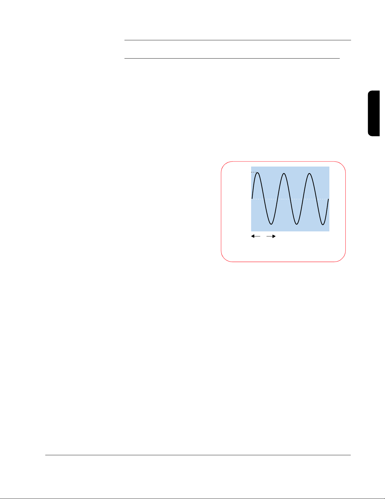
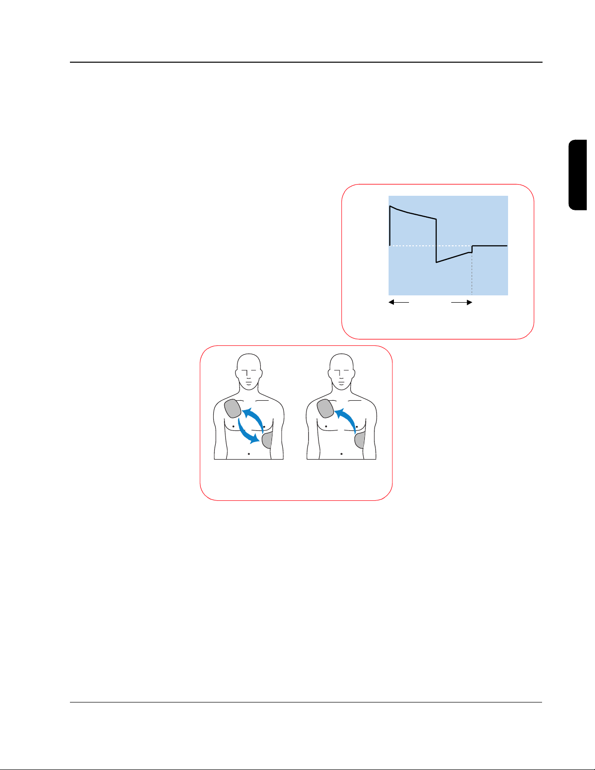
The basic difference between
monophasic and biphasic
waveforms is the direction of
current flow between the
defibrillation pads. With a
monophasic waveform, the
current flows in only one
direction. With a biphasic
Monophasic WaveformBiphasic Waveform
waveform, the current flows in
one direction and then
Defibrillation Current Flow
reverses and flows in the
opposite direction. Looking at
the waveforms, a monophasic waveform has one positive pulse, whereas a
biphasic starts with a positive pulse that is followed by a negative one.
In the process of developing the biphasic truncated exponential waveform for
use in AEDs, valuable lessons have been learned:
1. Not all waveforms are equally effective. How the energy is delivered (the
waveform used) is actually more important than how much energy is delivered.
Philips Medical Systems
2. Compensation is needed in the waveform to adjust for differing patient
impedances because the effectiveness of the waveform may be affected
by patient impedance. The patient impedance can vary due to the energy
delivered, electrode size, quality of contact between the electrodes and
SMART Biphasic Waveform
Page 22
3-4
the skin, number and time interval between previous shocks, phase of ventilation, and the size of the chest.
3. Lower energy is better for the patient because it reduces post-shock dysfunction. While this is not a new idea, it has become increasingly clear as
more studies have been published.
The characteristics for the monophasic damped sine and monophasic
truncated exponential waveforms are specified in the AAMI standard
DF2-1989; the result is that these waveforms are very similar from one
manufacturer to the next.
There is no standard for biphasic waveforms, each manufacturer has
designed their own. This has resulted in various wave-shapes depending
on the design approach used. While it is generally agreed that biphasic
waveforms are better than the traditional monophasic waveforms, it is also
true that different levels of energy are required by different biphasic
waveforms in order to be effective.
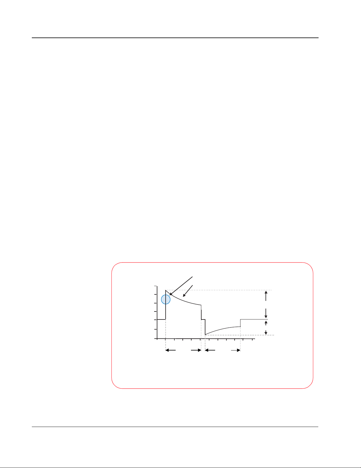
SMART Biphasic
SMART Biphasic is the patented waveform used by all HeartStart AEDs. It is
an impedance-compensating, low energy (<200 J), low capacitance (100
µF), biphasic truncated exponential (BTE) waveform that delivers a fixed
energy of 150 J for defibrillation. HeartStart was the first company to develop
a biphasic waveform for use in AEDs.
Safety Check impedance measurement
2000
1500
1000
500
0
Voltage (v)
-500
-1 0 1
SMART Biphasic Waveform
Waveform adjustment to impedance measurement
2
4
398
Phase I
675
Phase II
10
Time (msec)
+ Polarity
- Polarity
Philips Medical Systems
TECHNICAL REFERENCE GUIDE
Page 23
3-5
The SMART Biphasic waveform developed by Heartstream compensates for
different impedances by measuring the patient impedance during the
discharge and using that value to adjust the duration of the waveform to
deliver the desired 150 joules. Since the starting voltage is sufficiently large,
the delivered energy of 150 joules can be accomplished without the duration
ever exceeding 20 milliseconds. The distribution of the energy between the
positive and negative pulses was fine tuned in animal studies to optimize
defibrillation efficacy and validated in studies conducted in and out of the
hospital environment.
Different waveforms have different dosage requirements, similar to a dosage
associated with a medication. “If energy and current are too low, the shock
will not terminate the arrhythmia; if energy and current are too high,
5
myocardial damage may result.” (I-63)
The impedance compensation used in
the SMART Biphasic waveform results in an effective waveform for all
patients. The SMART Biphasic waveform has been demonstrated to be just
as effective or superior for defibrillating VF when compared to other
waveforms and escalating higher energy protocols.
3
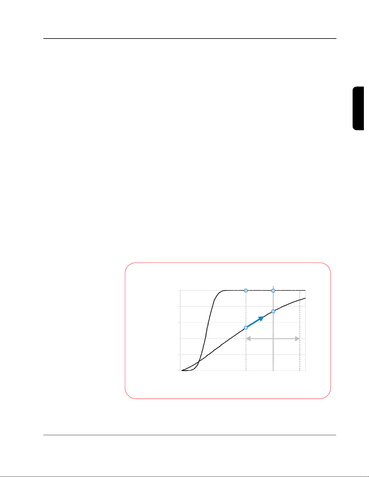
Understanding Fixed Energy
The BTE waveform has an advantage over the monophasic waveforms related
to the shape of the defibrillation response curve. The following graph, based
on Snyder et al., demonstrates the difference between the defibrillation
response curves for the BTE and the MDS waveform.
Isolated Rabbit Heart
Fixed-energy dose
100%
80%
60%
40%
20%
Probability of Defibrillation
0%
Philips Medical Systems
Based on data from Snyder et al., Resuscitation 2002; 55:93 [abstract]
NO NEED TO ESCALATE
SMART Biphasic
ESCALATION REQUIRED
Edmark MDS
05
Current (amperes)
Patient-to-patient
variation
SMART Biphasic Waveform
Page 24

3-6
With the gradual slope of the MDS waveform, it is apparent that as current
increases, the defibrillation efficacy also increases. This characteristic of the
MDS response curve explains why escalating energy is needed with the MDS
waveform; the probability of defibrillation increases with an increase in peak
current, which is directly related to increasing the energy.
For a given amount of energy the resulting current level can vary greatly
depending on the impedance of the patient. A higher-impedance patient
receives less current, so escalating the energy is required to increase the
probability of defibrillation.
The steeper slope of the BTE waveform, however, results in a response curve
where the efficacy changes very little with an increase in current, past a
certain current level. This means that if the energy (current) level is chosen
appropriately, escalating energy is not required to increase the efficacy. This
18
fact, combined with the lower energy requirements of BTE waveforms,
means that it is possible to choose one fixed energy that allows any patient to
be effectively and safely defibrillated.
Evidence-Based Support for the SMART Biphasic
Waveform
Using a process outlined by the American Heart Association (AHA) in 1997,6
the Heartstream team put the SMART Biphasic waveform through a rigorous
sequence of validation studies. First, animal studies were used to test and
fine-tune the waveform parameters to achieve optimal efficacy. Electrophysiology laboratory studies were then used to validate the waveform on
humans in a controlled hospital setting. Finally, after receiving FDA clearance
for the HeartStart AED, post-market studies were used to prove the efficacy
of the SMART Biphasic waveform in the out-of-hospital,
emergency-resuscitation environment.
Even when comparing different energies delivered with a single monophasic
waveform, it has been demonstrated that lower-energy shocks result in fewer
post shock arrhythmias.
waveform has several clinical advantages. It has equivalent efficacy to higher
energy monophasic waveforms but shows no significant ST segment change
from the baseline.
when the biphasic waveform is used.
biphasic waveform has improved performance when anti-arrhythmic drugs are
12,13
present,
and with long duration VF.
demonstrated improved neurological outcomes for survivors defibrillated with
SMART Biphasic when compared to patients defibrillated with monophasic
waveforms.
15
7
Other studies have demonstrated that the biphasic
8
There is also evidence of less post shock dysfunction
9,10,11,29
14,20
There is evidence that the
A more recent study has also
Philips Medical Systems
TECHNICAL REFERENCE GUIDE
Page 25

3-7
The bottom line is that the SMART Biphasic waveform has been
demonstrated to be just as effective or superior to monophasic waveforms at
defibrillating patients in VF. In addition, there are indications that patients
defibrillated with the SMART Biphasic waveform suffer less dysfunction than
those defibrillated with conventional escalating-energy monophasic
waveforms. SMART Biphasic has been used in AEDs for over five years, and
there are numerous studies to support the benefits of this waveform, including
out-of-hospital data with long-down-time VF.
SMART Biphasic Superior to Monophasic
Researchers have produced over 18 peer-reviewed manuscripts to prove the
efficacy and safety of the SMART Biphasic waveform. Ten of these are
out-of-hospital studies that demonstrated high efficacy of the SMART
Biphasic waveform on long-down-time patients in emergency environments.
No other waveform is supported by this level of research.
27
Using criteria established by the AHA in its 1997 Scientific Statement,
15
data from the ORCA study
demonstrate that the 150J SMART Biphasic
waveform is superior to the 200J - 360J escalating energy monophasic
waveform in the treatment of out-of-hospital cardiac arrest. This is true for
one-shock, two-shock, and three-shock efficacy and return of spontaneous
circulation.
the
3
Philips Medical Systems
SMART Biphasic Waveform
Page 26

3-8
Key Studies
waveforms studied results
1992
1994
1995 171 patients (electrophysiology laboratory). First-shock efficacy of biphasic
1995
1996
1997
low-energy vs. high-energy
damped sine monophasic
biphasic vs. damped sine
monophasic
low-energy truncated
biphasic vs. high-energy
damped sine monophasic
115 J and 139 J truncated
biphasic vs. 200 J and 360
J damped sine
monophasic
249 patients (emergency resuscitation). Low-energy and high-energy damped
sine monophasic are equally effective. Higher energy is associated with
increased incidence of A-V block with repeated shocks.
19 swine. Biphasic shocks defibrillate at lower energies, and with less
post-shock arrhythmia, than monophasic shocks.
damped sine is superior to high-energy monophasic damped sine.
30 patients (electrophysiology laboratory). Low-energy truncated biphasic and
high-energy damped sine monophasic equally effectiveness.
7
16
17
18
294 patients (electrophysiology laboratory). Low-energy truncated biphasic and
high-energy damped sine monophasic are equally effective. High-energy
monophasic is associated with significantly more post-shock ST-segment
changes on ECG.
18 patients (10 VF, emergency resuscitation). SMART Biphasic terminated VF at
higher rates than reported damped sine or truncated exponential monophasic.
8
19
1998 30 patients (electrophysiology laboratory). High-energy monophasic showed
significantly greater post-shock ECG ST-segment changes than SMART
SMART Biphasic vs.
1999 286 patients (100 VF, emergency resuscitation). First-shock efficacy of SMART
standard high-energy
monophasic
Biphasic.
Biphasic was 86% (compared to pooled reported 63% for damped sine
monophasic); three or fewer shocks, 97%; 65% of patients had organized rhythm
at hand-off to ALS or emergency personnel.
9
20
1999
1999
low-energy (150 J) vs.
high-energy (200 J)
biphasic
low-capacitance biphasic
vs. high-capacitance
biphasic
1999
SMART Biphasic vs.
escalating high-energy
2000
TECHNICAL REFERENCE GUIDE
monophasic
116 patients (emergency resuscitation). At all post-shock assessment times (3 -
60 seconds) SMART Biphasic patients had lower rates of VF. Refibrillation rates
were independent of waveform.
10
20 swine. Low-energy biphasic shocks increased likelihood of successful
defibrillation and minimized post-shock myocardial dysfunction after prolonged
21
arrest.
10 swine. Five of five low-capacitance shock animals were resuscitated,
compared to two of five high-capacitance at 200 J. More cumulative energy and
longer CPR were required for high-capacitance shock animals that survived.
22
10 swine. Stroke volume and ejection fraction progressively and significantly
reduced at 2, 3, and 4 hours post-shock for monophasic animals but improved for
biphasic animals.
11
338 patients (115 VF, emergency resuscitation). Demonstrated superior
defibrillation performance in comparison with escalating, high-energy
monophasic shocks in out-of hospital cardiac arrest. SMART Biphasic
defibrillated at higher rates than MTE and MDS, with more patients achieving
ROSC. Survivors of SMART Biphasic resuscitation were more likely to have
good cerebral performance at discharge, and none had coma (vs. 21% for
monophasic survivors).
15
Philips Medical Systems
Page 27

Frequently Asked Questions
Are all biphasic waveforms alike?
No. Different waveforms perform differently, depending on their shape,
duration, capacitance, voltage, current, and response to impedance.
Different biphasic waveforms are designed to work at different energies.
Consequently, an appropriate energy dose for one biphasic waveform
may be inappropriate for a different waveform.
There is evidence to suggest that a biphasic waveform designed for
low-energy defibrillation may result in overdose if applied at high energies
(the Tang AHA abstract from 1999 showed good resuscitation
performance for the SMART Biphasic waveform, but more shocks were
required at 200 J than at 150 J
designed for high-energy defibrillation may not defibrillate effectively at
lower energies. (The Tang AHA abstract from 1999 showed poor
resuscitation performance for the 200 µF capacitance biphasic waveform
at 200 J compared to the 100 µF capacitance biphasic waveform
[SMART Biphasic] at 200 J.
that the 200 µF capacitance biphasic waveform performed better at 200
23
J than at 130 J.
)
21
). Conversely, a biphasic waveform
22
Higgins manuscript from 2000 showed
3-9
3
It is consequently necessary to refer to the manufacturer's
recommendations and the clinical literature to determine the proper
dosing for a given biphasic waveform. The recommendations for one
biphasic waveform should not be arbitrarily applied to a different biphasic
waveform. “It is likely that the optimal energy level for biphasic
defibrillators will vary with the units' waveform characteristics. An
appropriate energy dose for one biphasic waveform may be inappropriate
24
for another.”
SMART Biphasic was designed for low energy defibrillation, while some
other biphasic waveforms were not. It would be irresponsible to use a
waveform designed for high energy with a low-energy protocol just to
satisfy the current AHA recommendation.
How can the SMART Biphasic waveform be
more effective at lower energy?
The way the energy is delivered makes a significant difference in the
Philips Medical Systems
efficacy of the waveform. Electric current has been demonstrated to be
the variable most highly correlated with defibrillation efficacy. The SMART
Biphasic waveform uses a 100 µF capacitor to store the energy inside the
SMART Biphasic Waveform
Page 28

3-10
AED; other biphasic waveforms use a 200 µF capacitor to store the energy.
The energy (E) stored on the capacitor is given by the equation:
E = ½ C V
2
The voltage (V) and the current (I) involved with defibrillating a patient are
related to the patient impedance (R) by the equation:
V = I R
Peak Current Levels
Low Impedance (50 ohms)
70
60
50
40
30
20
10
Current (amps)
0
360 J
Monophasic
150 J SMART
Biphasic
MPC 200 J
Biphasic
MPC 300 J
Biphasic
MPC 360 J
Biphasic
For the 200 µF capacitance biphasic waveform to attain similar levels of
current to the SMART Biphasic (100 µF) waveform, it must apply the same
voltage across the patient's chest. This means that to attain similar current
levels, the 200 µF biphasic waveform must store twice as much energy on the
capacitor and deliver much more energy to the patient; the graph at right
demonstrates this relationship. This is the main reason why some biphasic
waveforms require higher energy doses than the SMART Biphasic waveform
to attain similar efficacy.
Philips Medical Systems
TECHNICAL REFERENCE GUIDE
Page 29
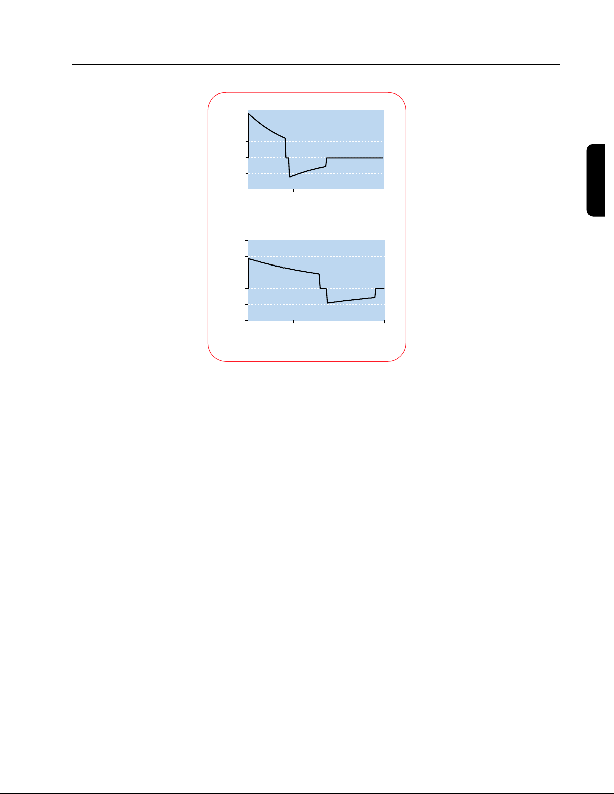
45
30
15
0
-15
Patient Current (amps)
-30
0 0.005 0.01 0.015
45
30
15
0
-15
Patient Current (amps)
-30
0 0.005 0.01 0.015
SMART Biphasic
(C =100 µF)
Time (seconds)
Other biphasic
(C=200 µF)
Time (seconds)
3-11
The illustrations to the left
show the SMART Biphasic
waveform and another
biphasic waveform with a
higher capacitance, similar to
that used by another AED
manufacturer. The low
capacitance used by the
patented SMART Biphasic
waveform delivers energy
more efficiently. In an animal
study using these two
waveforms, the SMART
Biphasic waveform
successfully resuscitated all
animals and required less
cumulative energy and shorter
CPR time than the other
biphasic waveform, which
resuscitated only 40% of the
animals.
22
3
The amount of energy needed depends on the waveform that is used. SMART
Biphasic has been demonstrated to effectively defibrillate at 150 J in
15
out-of-hospital studies.
Biphasic waveform would not be more effective at higher energies
Animal studies have indicated that the SMART
21
and this
seems to be supported with observed out-of-hospital defibrillation efficacy of
96% at 150 J.
15
Is escalating energy required?
Not with SMART Biphasic technology. In the “Guidelines 2000,”5 the AHA
states, “Energy levels vary with the type of device and type of waveform used.”
(I-90) The SMART Biphasic waveform has been optimized for ventricular
defibrillation efficacy at 150 J. Referring to studies involving the SMART
Biphasic waveform, it states, “This research indicates that repetitive
lower-energy biphasic waveform shocks (repeated shocks at < 200 J) have
equivalent or higher success for eventual termination of VF than defibrillators
that increase the current (200, 300, 360 J) with successive shocks
(escalating).” (I-90)
Philips Medical Systems
All HeartStart AEDs use the 150 J SMART Biphasic waveform. Two products,
the HeartStart XL and XLT, provide an AED mode as well as manual
defibrillation, synchronized cardioversion, electrocardiogram monitoring,
SMART Biphasic Waveform
Page 30

3-12
SpO2 monitoring, and non-invasive pacing. Selectable energy settings (from
5 to 200 J for the XLT or 2 to 200 J for the XL) are available in the XL and XLT
only in the manual mode. A wider range of energy settings is appropriate in a
device designed for use by advanced life support (ALS) responders who may
perform manual pediatric defibrillation or synchronized cardioversion, as
energy requirements may vary depending on the type of cardioversion
25,26
rhythm.
For treating VF in patients over eight years of age in the AED
mode, however, the energy is preset to 150 J.
Some have suggested that a patient may need more than 150 J with a BTE
waveform when conditions like heart attacks, high-impedance, delays before
the first shock, and inaccurate electrode pad placement are present. This is
not true for the SMART Biphasic waveform, as the evidence presented in the
following sections clearly indicates. On the other hand, the evidence indicates
that other BTE waveforms may require more than 150 J for defibrillating
patients in VF.
Heart Attacks
One manufacturer references only animal studies using their waveform to
support their claim that a patient may require more than 200 J for cardiac
arrests caused by heart attacks (myocardial infarction) when using their
waveform. The SMART Biphasic waveform has been tested in the real world
with real heart attack victims and has proven its effectiveness at terminating
ventricular fibrillation (VF). In a prospective, randomized, out-of-hospital study,
the SMART Biphasic waveform demonstrated a first shock efficacy of 96%
versus 59% for monophasic waveforms, and 98% efficacy with 3 shocks as
15
opposed to 69% for monophasic waveforms.
Fifty-one percent of the
victims treated with the SMART Biphasic waveform were diagnosed with
acute myocardial infarction. The published evidence clearly indicates that the
SMART Biphasic waveform does not require more than 150 J for heart attack
victims.
High-Impedance Patients
High impedance patients do not pose a problem with the low energy SMART
Biphasic waveform. Using a patented method, SMART Biphasic technology
automatically measures the patient's impedance and adjusts the waveform
dynamically during each shock to optimize the waveform for each shock on
each patient. As demonstrated in published, peer-reviewed clinical literature,
the SMART Biphasic waveform is as effective at defibrillating patients with
high impedance (greater than 100 ohms) as it is with low-impedance
19
patients.
The bottom line is that the SMART Biphasic waveform does not
require more than 150 J for high-impedance patients.
Philips Medical Systems
TECHNICAL REFERENCE GUIDE
Page 31

3-13
Delays Before the First Shock
The SMART Biphasic waveform is the only biphasic waveform to have
extensive, peer-reviewed and published emergency resuscitation data for
long-duration VF. In a randomized out-of-hospital study comparing the
low-energy SMART Biphasic waveform to high-energy escalating
monophasic waveforms, the average collapse-to-first-shock time was 12.3
minutes. Of the 54 patients treated with the SMART Biphasic waveform,
100% were successfully defibrillated, 96% on the first shock and 98% with
three or fewer shocks. With the monophasic waveforms, only 59% were
defibrillated on the first shock and only 69% with three or fewer shocks.
Seventy-six percent of the patients defibrillated with the SMART Biphasic
waveform experienced a return of spontaneous circulation (ROSC), versus
only 55% of the patients treated with high-energy monophasic waveforms.
15
In a post-market, out-of-hospital study of 100 VF patients defibrillated with the
SMART Biphasic waveform, the authors concluded, “Higher energy is not
20
clinically warranted with this waveform.”
SMART Biphasic does not require
more than 150 J when there are delays before the first shock.
3
Inaccurate Electrode Pad Placement
The claim that more energy is possibly required if the pads are not placed
properly is a purely speculative argument with no basis in scientific evidence.
However, common sense would suggest that if a given biphasic waveform
needs more energy when pads are located properly, why would it perform any
better if the pads were placed sub-optimally? Once again, the real world data
demonstrates high efficacy with the SMART Biphasic waveform in
15,20
out-of-hospital studies.
These studies included hundreds of AED users
with a variety of different backgrounds.
Is there a relationship between waveform, energy
level, and post-shock dysfunction?
Yes. Higher-energy defibrillation waveforms - whether monophasic or biphasic
- are associated with increased post-shock cardiac dysfunction.
There is a difference between damage and dysfunction. In the context of
post-shock cardiac assessment, “damage” can be defined as irreversible cell
death, as measured by various enzyme tests. “Dysfunction” is reflected in
reduced cardiac output as a result of reversible myocardial stunning.
Dysfunction can result in significantly reduced cardiac output for many hours
Philips Medical Systems
post-resuscitation. Waveforms that do not cause damage can cause
dysfunction.
SMART Biphasic Waveform
Page 32

3-14
100%
90%
80%
70%
60%
50%
40%
Heart Function
30%
20%
10%
(stroke volume as % of pre-arrest baseline)
0%
Severe Disability
Moderate Disability
Good Brain Function
Low-energy SMART Biphasic
78% 78%
58%
Escalating high-energy monophasic
12345
7%
7%
86%
50%
Hours Post-Shock
100%
80%
60%
40%
20%
88%
45%
21%
5%
21%
53%
Comatose
Severe Disability
Moderate Disability
Good Brain Function
0%
SMART Biphasic
High-energy monophasic
Evidence of this dysfunction includes electrocardiogram (ECG)
8,28
abnormalities.
A study of escalating-energy monophasic waveforms found
that increased levels of delivered energy were associated with increased
evidence of impaired myocardial contractility and perfusion failure. The
authors conclude: “The severity of post-resuscitation myocardial dysfunction
is related, at least in part, to the magnitude of electrical energy of the
29
delivered shock.”
conclusion for biphasic as well as monophasic waveforms.
Several other studies also provide data to support this
21,30,31
Post-resuscitation brain dysfunction is another important area that warrants
further study. In a randomized study of 115 out-of-hospital SCA patients with
VF, 54 were shocked with the SMART Biphasic waveform and the remainder
with escalating high-energy monophasic devices. In this study, 87% of
SMART Biphasic survivors had good brain function when discharged from
Philips Medical Systems
TECHNICAL REFERENCE GUIDE
Page 33

the hospital, as opposed to only 53% of monophasic escalating-energy
survivors. None of the SMART Biphasic patients experienced post-shock
coma, while 21% of monophasic survivors did.
15
How does SMART Biphasic compare to other
biphasic waveforms?
3-15
While there is a large body of literature published about the SMART Biphasic
waveform, there is very little published research about other biphasic
defibrillation waveforms.
Comparing waveform results within a single, controlled study can yield
meaningful information. However, comparing the results from separate
studies can be extremely misleading, due to any number of uncontrolled
differences from study to study. The same waveform can perform differently in
different studies, depending on how each study is set up.
The results of an animal study comparing the SMART Biphasic waveform to a
type of biphasic waveform used by another manufacturer establish that the
SMART Biphasic waveform increases the likelihood of successful
defibrillation, minimizes post-shock myocardial dysfunction, and requires less
cumulative energy.
22
Is there a standard for biphasic energy levels?
No. The data supporting low-energy biphasic defibrillation has been reviewed
by the American Heart Association (AHA), which found the therapy to be
“safe, effective, and clinically acceptable.” As stated by the AHA, “A review of
previous AHA guidelines for the [monophasic] energy sequence 200 J- 300
J-360 J reveals that the evidence supporting this reputed 'gold standard' is
largely speculative and is based largely on common sense
extrapolation....Multiple high energy shocks could easily result in more harm
than good.“
32
3
Since there are differences between the biphasic waveforms available, the
proper energy level for a particular biphasic waveform depends on how it was
designed and should be specified by the manufacturer. The proper energy
level for SMART Biphasic is 150 J, as demonstrated by the studies
completed. When referencing these studies and the SMART Biphasic
waveform, the AHA states that, “The growing body of evidence is now
considered sufficient to support a Class IIa recommendation for this low
5
energy, BTE waveform.“
Philips Medical Systems
evidence,” “Considered standard of care,” and “Considered intervention of
choice by a majority of experts.“
The AHA defines a Class IIa as, “Good/very good
5
SMART Biphasic Waveform
Page 34

3-16
In the same guidelines, the AHA also issued a similar recommendation for the
general practice of low-energy biphasic defibrillation, but cautioned that, “at
this time no studies have reported experience with other biphasic waveforms
in long-duration VF in out-of-hospital arrest. When such data becomes
available, it will need to be assessed by the same evidence evaluation
process as used for the biphasic defibrillator and this guidelines process.”
Commitment to SMART Biphasic
All HeartStart defibrillator products use the 150 J SMART Biphasic
waveform. The HeartStart XL and XLT are manual defibrillators designed to be
used by advanced cardiac life support personnel, but they also include an
AED mode. These products provide selectable energy settings from 2 to 200
J in the manual mode but utilize a constant 150 J in the AED mode.
Some waveforms may need more than 150 J for defibrillation, but the SMART
Biphasic waveform does not. Published clinical evidence indicates that the
SMART Biphasic waveform does not require more than 150 J to effectively
defibrillate, even if the patient has experienced a heart attack, has a higher
than normal impedance, or if there have been delays before the first shock is
delivered. Published clinical evidence also indicates that there is increased
dysfunction associated with high-energy shocks.
7,8,29,30,33
Since the SMART Biphasic waveform has been proven effective for
defibrillation at 150 J, there is no need to deliver more energy.
Philips Medical Systems
TECHNICAL REFERENCE GUIDE
Page 35

3-17
References
1 Jones JL and Jones RE. Postshock arrhythmias - a possible cause of unsuccessful
defibrillation. Critical Care Medicine 1980;8(3):167-71.
2 Winkle RA, et al. Improved low energy defibrillation energy in man with the use of a
biphasic truncated exponential waveform. American Heart Journal
1989;117:122-127.
3 Bardy GH et al. A prospective, randomized evaluation of biphasic vs monophasic
waveform pulses on defibrillation efficacy in humans. Journal of the American College
of Cardiology 1989;14:728-733.
4 Schwartz JF, et al. Optimization of biphasic waveforms for human nonthoracotomy
defibrillation. Circulation 1993;33:2646-2654.
5 American Heart Association. Guidelines 2000 for Cardiopulmonary Resuscitation
and Emergency Cardiovascular Care August, 2000
6 American Heart Association Task Force on Automatic External Defibrillation,
Subcommittee on AED Safety and Efficacy. AHA Scientific Statement. Automatic
external defibrillators for public access defibrillation: Recommendations for specifying
and reporting arrhythmia analysis algorithm performance, incorporating new
waveforms, and enhancing safety. Circulation 1997;95:1277-1281.
7 Weaver WD, et al. Ventricular defibrillation-A comparative trial using 175J and 320J
shocks. New England Journal of Medicine 1982;307:1101-1106.
8 Bardy GH, et al. Multicenter comparison of truncated biphasic shocks and standard
damped sine wave monophasic shocks for transthoracic ventricular defibrillation.
Circulation 1996;94:2507-2514.
9 Reddy RK, et al. Biphasic transthoracic defibrillation causes fewer ECG ST-segment
changes after shock. Annals of Emergency Medicine 1997;30:127-134.
10 Gliner BE and White RD. Electrocardiographic evaluation of defibrillation shocks
11 Tang W, Weil MH, Sun Shijie, et al. Defibrillation with low-energy biphasic waveform
12 Ujhelyi, et al. Circulation 1995;92(6):1644-1650
13 Kopp, et al. PAC E 1995;18:872
14 Poole JE, et al. Low-energy impedance-compensating biphasic waveforms terminate
15 Schneider T, Martens PR, Paschen H, et al. Multicenter, randomized, controlled trial of
16 Gliner BE, et al. Transthoracic defibrillation of swine with monophasic and biphasic
17 Greene HL, DiMarco JP, Kudenchuk PJ, et al. Comparison of monophasic and
18 Bardy GH, Gliner BE, Kudenchuk PJ, et al. Truncated biphasic pulses for
19 White RD. Early out-of-hospital experience with an impedance-compensating
20 Gliner BE, et al. Treatment of out-of-hospital cardiac arrest with a low-energy
Philips Medical Systems
21 Tang W, et al, Effects of low- and higher-energy biphasic waveform defibrillation on
delivered to out-of-hospital sudden cardiac arrest patients. Resuscitation
1999;41:133-144.
reduces the severity of post-resuscitation myocardial dysfunction after prolonged
cardiac arrest. Journal of Critical Care Medicine 1999;27:A43.
ventricular fibrillation at high rates in victims of out-of-hospital cardiac arrest. Journal
of Electrophysiology 1997;8:1373-1385.
150-joule biphasic shocks compared with 200- to 360-joule monophasic shocks in
the resuscitation of out-of-hospital cardiac arrest victims. Circulation
2000;102:1780-1787.
waveforms. Circulation 1995;92:1634-1643.
biphasic defibrillating pulse waveforms for transthoracic cardioversion. American
Journal of Cardiology 1995;75:1135-1139.
transthoracic defibrillation. Circulation 1995;64:2507-2514.
low-energy biphasic waveform automatic external defibrillator. Journal of
Interventional Cardiac Electrophysiology 1997;1:203-208.
impedance-compensating biphasic waveform automatic external defibrillator.
Biomedical Instrumentation & Technology 1998;32:631-644.
success of resuscitation and post-resuscitation myocardial dysfunction after
prolonged cardiac arrest. Circulation (supplement)1999:100(18):I-662 (abstract).
3
SMART Biphasic Waveform
Page 36

3-18
22 Tang W, et al, Low capacitance biphasic waveform shocks improve immediate
resuscitation after prolonged cardiac arrest. Circulation
(supplement)1999:100(18):I-663 (abstract).
23 Higgins SL, et al. A Comparison of Biphasic and Monophasic Shocks for External
Defibrillation. PreHospital Emergency Care 2000; 4:305-313.
24 ECRI. External Biphasic Defibrillators, Should You Catch the Wave? Health Devices.
June 2001, Volume 30, Number 6.
25 American Heart Association. Textbook of Advanced Cardiac Life Support 1997;1-34.
26 Mittal S, Ayati S, Stein KM, et al. Transthoracic cardioversion of atrial fibrillation:
comparison of rectilinear biphasic versus damped sine wave monophasic shocks.
Circulation 2000 101(11):1282-1287.
27 Kerber RE, et al. Automatic external defibrillators for public access defibrillation:
recommendations for specifying and reporting arrhythmia analysis algorithm
performance, incorporating new waveforms, and enhancing safety. Circulation. 1997;
95:1677-1682.
28 Reddy RK, et al. Biphasic transthoracic defibrillation causes fewer ECG ST-segment
changes after shock. Annals of Emergency Medicine 1997;30:127-134.
29 Xie J, et al. High-energy defibrillation increases the severity of postresuscitation
myocardial function. Circulation 1997;96:683-688.
30 Tokano T, et al. Effect of ventricular shock strength on cardiac hemodynamics. Journal
of Cardiovascular Electrophysiology 1998;9:791-797.
31 Cates AW, et al. The probability of defibrillation success and the incidence of
postshock arrhythmia as a function of shock strength. PACE 1994;117:1208-1217.
32 Cummins RO, et al. Low-energy biphasic waveform defibrillation: Evidence-based
review applied to emergency cardiovascular care guidelines: A statement for
healthcare professionals from the American Heart Association Committee on
Emergency Cardiovascular Care and the Subcommittees on Basic Life Support,
Advanced Cardiac Life Support, and Pediatric Resuscitation. Circulation 1998;97:1
33 Tang W, et al. Defibrillation with low-energy biphasic waveform reduces the severity of
post-resuscitation myocardial dysfunction after prolonged cardiac arrest. Journal of
Critical Care Medicine. (Abstract) 1999;27:A43.
TECHNICAL REFERENCE GUIDE
Philips Medical Systems
Page 37

4 SMART Analys is
SMART Analysis refers to the proprietary analysis system used in HeartStart
AEDs that analyzes a pa ti ent's ECG and determines wh et her a shock should
be deli v ered. It c onsists of t h r e e parts: pad contact quality, artifact detection,
and arrhythmia detection. These three parts work together to enable the
defibrillator to read an ECG and evaluate the available information to
determine if a s ho ck is appropriate .
Pad Contac t Quality
This part of the analysis system continuously monitors the patient impedance
to ensure that it remains within the appropriate range. This impedance
measurement is a low signal measurement made throu gh the front -end
circuitry of the defibrillator and is different from the impedance measurement
made at the beginning of the SMART Biphasic waveform.
If the measured impedance is too high, it may indicate that the pads are not
properly applied or tha t ther e may be a p roblem with the pad/skin interfa ce.
Unless this is corrected, the defibrillator will not be able to read the ECG
effectively to determine whether a s hock is advised . Poor pad connection can
also cause a problem with the delivery of current to the patient. If the patient
impedance is above the appropriate range, the HeartStart AED will issue
voice prompts intended to direct the user's attention to the pads with
statements like “Apply Pads,” “Press Pads Firmly,” or “Poor Pads Contact” to
correct the situation.
4
Artifact Detection
Whenever any electrical signal (such as an ECG) is measured, there is
invariably a certain amount of electrical noise in the environment that can
interfere with an accurate measurement. Artifact detection is important in an
ECG analysis system becau se it al lows d etect ion of this extraneous electrica l
noise so that it can either b e filtered out or compensated for . Motion d etection
is one way of dealing with this noise, but it is only imp o r tant if the motion
produces artifact on the ECG signal. Any artifact that is undetected can lead
to incorrect decisions by the algorithm and can cause incorrect or delayed
treatment of the patient.
Philips Medical Systems
Artifact can be caused in a variety of ways, including CPR, agonal breathing,
transportation, patient handling, and the presence of a pacemaker in the
patient. The action taken depend s on how the artif ac t looks in relation to the
ECG signal.
4-1
Page 38

4-2
Artifact detection in HeartStart AEDs is accomplished by measuring the
amount of static electricit y sensed by the pads; this static is considered to be
artifact signal. T hi s artifact signal is then compared to the ECG signal. If they
correlate, then artifa ct is detected and appropriate v oice prompts ar e given so
the user can take appropri ate ac tion. However, if it d oes not correla te wit h the
ECG, then analysis proceeds and the defibrillator makes shock/no-shock
decisions.
If the amplitude of t he und er lying ECG signal is small compar ed t o an a rt ifact
signal, then the HeartStart AED will respond by giving voice prompts that tell
the user “Do not touch the patient,” “Analyzing interrupted,” or “Patient and
device must remain still.” In this situation, the defibril lator can not accurately
analyze the underlying ECG because the amount of electrical noise present
has corrupted the ECG signal. The AED messages given in this situation are
designed to prompt the user to take actions that will stop or minimize the
artifact in the environment.
If the amplitude of the ECG signal is sufficiently high comp ar ed to the artifact
signal or if the artifact does not correlat e with the ECG signal, the artifact will
not interfere with the normal operation of the AED. In these cases, the
defibrillator reco gni zes tha t ar tifa ct is present, b ut t he defib r ill ator can
continue to make shock decisions and deliver a shock if appropriate.
In the event that the patient has an implanted pacemaker, HeartStart AEDs
have special filters that remove the pacemaker artifact and allow the
defibrillator to shock the patient i f appropriate. The ECG shown on the AED's
display and the ECG stored on the data card still have the pacemaker spikes
represented, but the ECG used by the algorithm have the spikes removed.
The two strips in the following figure represent the ECG before and after the
pacemaker artifact is filtered out.
Philips Medical Systems
TECHNICAL REFERENCE GUIDE
Page 39

Millivolts
2
1
0
-1
-2
0 0.4 0.8 1.2 1.6 2.0 2.4 2.8 3.2 3.6 4.0 4.4
Seconds
Before Filtering: Underlying rhythm VF, pacemaker artifactBefore Filtering: Underlying rhythm VF, pacemaker artifact
4-3
2
1
0
-1
Millivolts
-2
0 0.4 0.8 1.2 1.6 2.0 2.4 2.8 3.2 3.6 4.0 4.4
Seconds
After Filtering: Underlying rhythm VF, no pacemaker artifactAfter Filtering: Underlying rhythm VF, no pacemaker artifact
Even with a sophisticated artifact detection system, not all artifact can be
detected during the us e of the A ED. This is wh y it is imp or tant to list en to the
voice prompts given by the AED and to not touch the patient while it is
analyzing the ECG. On th e following page is an example of r apid CP R done
in such a way that it was not detected by the analysis system. The second
strip shows the underlying asystole present when CPR is stopped. Because
HeartStart AEDs continually monitor the ECG and look for changes in the
rhythm, the unit quickly disarmed automatically in this situation when CPR
was discontinued and no shock was delivered to the patient. Asystole is not
considered a shockable rhythm.
4
Philips Medical Systems
SMART Anal ysis
Page 40

4-4
.
2 div/mV, 5 div/sec
CPR Artifact: Underlying rhythm asystole
2 div/mV, 5 div/sec
Post-CPR: Underlying rhythm asystole
Delivering a shock to a patient in asysto le wi ll not return the heart to a normal
rhythm and may actually prevent more ap p r opri ate therapi es from be ing
successful.
Arrhythmia Detection
A crucial fa ctor in the safety and perf ormance of an A ED is the device's abilit y
to accurately assess the cardiac state of the patient. The AED performs this
evaluation by sens ing electrical signals f rom th e p ati ent's heart via electrodes
and using a computerized algorithm to interpret the electrical signals and
make a therapy decisi o n .
The SMART Analysis system algo r ith m simul taneously looks at four key
indicators to determine whether a rhythm is shockable or non-shockable.
These four indicators are rate, conduction, stability and amplitude.
• Rate is determined by how many times the heart
beats per minute (bpm). A health y heart beats
60-100 bpm. Some normal rhythms can be very
fast. Therefore, it is important to have addition al
indicators in the analys is sy s tem of an AED.
• Conduction is determined by examining the “R”
wave of the QRS complex. A healthy “R” wave
appears as a narrow spike and indicates that
QRS complex
R-wave
Philips Medical Systems
TECHNICAL REFERENCE GUIDE
Page 41

4-5
electrical waves are flowing through the heart properly. A wide, rounded
“R” wave is indicative of an unhealthy heart.
• Stability is the repeatability of the QRS complexes. A healthy heart will
have repeatable, stable QRS complexes. An unhealthy heart will ha ve
chaotic, unstable complexes.
• Amplitude is a measure of magnitude of the heart's electri cal activity . A
heart that is in asystole, or “flatline,” will have a low-amplitude ECG.
Amplitude is very dependent on the patient and pads placement and is
therefore the least important of the four indicators.
SMART Analysis simultaneously measures the first three indicators above
over 4.5 second segm ents of ECG, and then classif ies each s egment of ECG
as shockable or non-shockable. Amplitude is used as a gating check to
determine if a strip is c ons id er ed shockable; i.e. the 4.5 second strip of ECG
must have at least a 100 µV peak-to-peak median amplitude in orde r for a
strip to be considered VF.
4.5 second strip
The AED must identify multiple ECG strips as shockable before it will allow
the device to charge. The device must then continue to see shockable strips
in order to allow a shock to be delivered. HeartStart AEDs differ from other
AEDs in that they continue to monitor the ECG even after a shock decision
has been made and the u nit h as ch arg ed; this me ans that th e He artStart A ED
will react to a change in rhythm and disarm if the rhythm becomes nonshockable.
4
If the device detects several consecutive strips that are non-shockable, it will
give a voice prompt that no shock is advi sed, inf o rm the user that it is safe to
touch the patient, and then transition into “monitor” mode. The device
continues to monitor the ECG, but it will give minimal voice prompts until it
Philips Medical Systems
identifies another strip as shockable. At this point it will transition back into
“analyze” mode where it will dir ect the us er to sto p touching the patient and
make a decision to shock the patient if appropriate.
SMART Anal ysis
Page 42

4-6
Shockable Rhyt hms
SMART Analysis is designed to shock ventricu lar fibrillation (VF), ven tr icular
flutte r, an d p o lymor p hic ventricul a r tachycardia (VT). These ar e the most
common rhythms associated with sudden cardi ac arr es t. In addi tion, it is
designed to avoid rhythms that are commonly accompanied by a pulse or
rhythms that would not benefit fr om an electrica l sh ock. The AHA states that
rhythms accompanied by a pulse should not be shocked because no benefit
will follow and d et erioration in rhythm may resu lt.
The algorith m use d i n Hea rtStart AEDs is different fr om the a lg o rithm us ed in
the HeartStart manual defib r illators, such as the Hea rt Start XL. AEDs are
designed to be used by lay rescuers, whereas manual defibrillators are
designed to b e used by trained medical per sonnel. The main diff erence is tha t
the algorithm in an AED should try to differentiate between ven tr icular
tachycardia tha t has a pulse and on e w ithout. The conseque nce of this is that
the HeartStart AEDs are more conservative in shoc ki ng inter med ia te r hythms
such as fine V F and VT th at d o n't m eet all criteria for inclusion in the
shockable VT rhythm category.
1
SMART Analysis has been designed to be conservative for stable
monomorphic tachycardias. The rate threshold for a shockable tachycardia
will vary from a minimum of about 160 bpm for rhythms with very slow
ventricular-like conduction to a maximum threshold of 600 bpm for rhythms
with healthy norma l conduction. T hus, rhythms w ith normal conduc tion will not
be shocked regardless of the rate.
The AHA has issued a Scientific Statement clearly identifying SVT as a
non-shockable rhythm, and re quiring a minimum defibrillator algorithm
2
specificity of 95% for this rhythm.
This high-spe cif icity requirement assumes
that a high-quality assess m ent of pe rfus ion s tatus has been made, there by
eliminating many S VTs from analysis by the defibril lator . T he H eartStart AED is
designed to issue a no-shoc k recommendation f or rhythms of sup raventricular
origin regardless of their rate, and has demonstrated 100% specificity when
tested against a database containing 1 00 examples of S VT wi th rates as hig h
as 255 beats per m i nute.
For rhythms that have poorer morpholo gi cal s tability such as polymo rphic VT
and VF, the rate threshold varies in a similar manner describ ed above. As
morphological stability degrades, the rate threshold will be progressively
reduced, approaching a minimum rate threshold of about 135 bpm.
Philips Medical Systems
1 American Heart Association (AH A) AED Task Force, Subcommittee on AED Safety & Efficacy.
Automatic External Defibrillators for Public Access Us e: Recommendations for Specifying and
Reporting Arrhythmia Analysis Algorithm Performance, Incorporation of New Waveforms, and
Enhancing Safety. Circulation 1997;95:1677-1682.
2 Kerber et al, Circulation, 1997; 95:1677-1682
TECHNICAL REFERENCE GUIDE
Page 43

4-7
Rate ~ 192 bpm
No Shock Advised
This adaptive desig n allows the rate threshold to be varied from a minimum
level f o r the mos t lethal V F rhyth m s , p roviding very high sensitiv ity, to
increasingly higher rate thresholds as the stability or conduction
characteristics approach normal, providing very high specificity. Borderli ne
rhythms, such as monomorphic tachycardias are treated conservatively, with
the expectation that if th ey are hemodyna mical ly uns table, then th e rhy thm will
soon exhibit shockable characteristics.
Two samples of monomorphic tachycardia ar e s hown below as examples of
border line rhythms that do not require sh o cks. Both of these rh ythms ar e of
supraventricular origin, with one known to be accompanied by a pulse.
SMART Analysis gives a no-shoc k reco mmendation for bot h of these rhythms.
4
Rate ~ 144 bpm
No Shock Advised
The next two samples are examples of flutter and polymorphic VT. These
rhythms represent ECGs that are not associated with a pulse and are
considered shockable forms of VT.
Philips Medical Systems
SMART Anal ysis
Page 44

4-8
.
Rate ~ 240 bpm
Rate ~ 288 bpm
Shock Advised
Shock Advised
In the back of the Hear tSta rt AED Instructions for Use manual, the statement
is made, “For safety reasons, some very low-amp litude or low-frequency
rhythms may not be interpreted as shockable VF rhythms. Also some VT
rhythms may not be interpreted as shockable rhythms.” As noted earlier in this
chapter, low amplitude/fre qu ency VF may somet imes be the result of pa tien t
handling, and some VT rhythms have been associated with a pulse.
The next example of VF shown would not be considered a shockable rhythm
because of its low frequency. In addition to the possibility of patient handling
generating this type of rhythm, there are studies that indicate that a fine VF
such as this would benefit from a minute or two of CPR before a shock is
attempted. CPR tends to oxygenate the myocardium and increase the
electrical activity of the heart, making it more susceptible to defibrillation.
TECHNICAL REFERENCE GUIDE
Philips Medical Systems
Page 45

4-9
Validatio n of A lg or it hm
Algorithm performance is evaluated by two criteria: sensitivity, which is the
ability of the algorithm to detect life-threatening ventricular arrhythmias, and
specificity, which is the ability of the alg or ithm to discriminate life-threatening
arrhythmias from normal rhythms or arrhyt hmia s tha t shoul d not be shocked.
field results
We developed a proprietary electrocardi ogram (ECG) analysis system tha t
provides an exceptional level of sensitivity and specificity.
ECG Analysis Performance
HeartStart AED validation results
a
meets AHA recommendationsb for adult defibrillation
rhythm class
AAMI DEF39 requirement
Shockable Rhythm —
ventricular fibrillation
Shockable Rhythm —
ventricular tachycardia
Non-Shockable
Rhythm — Normal
Sinus Rhythm
Non-Shockable
Rhythm — Asystole
Non-Shockable
Rhythm — All other
non-shockable
rhythms
a. The studies and data cited above are the result of extremely challenging rhythms that deliberately test the limits of AEDs. In clinical
situations, the actual sensi t ivity and specificity for the HeartStart AEDs have been significantly better, thereby validating
Heartstream’s rigorous pre-market testing of its algorithm.
b. American Heart Association (AHA) AED Task Force, Subcommittee on AED Safety & Efficacy. Automatic External Defibrillators for
Public Access Use: Recommendations for Specifying and Reporting Arrhythmia Analysis Algorithm Performance, Incorporation of
New Waveforms, and Enhancing Safety. Circulation 1997;95:1677-1682.
c. From Philips Medical Heartstream ECG rhythm databases.
sensitivity >90% 97%
sensitivity >75% 81%
specificity >99% 100%
specificity >95% 100%
specificity >95%
includes: SVT (R>100), SVD
(R≤100),
VEB, idioventricular, and
bradycardia
b
observed
performance
validation
results
(n=300)
(n=100)
(n=300)
(n=100)
100%
(n=450)
c
artifact-
free
99.1%
(n=106)
100%
(n=9)
100%
(n=15)
100%
(n=53)
99%
(n=101)
artifact
included
97 .3%
(n=111)
90%
(n=10)
100%
(n=17)
100%
(n=64)
95.6%
(n=114)
one-sided
confidence
90%
lower
limit
(87%)
(67%)
(97%)
(92%)
(88%)
4
b
In the original, out-of-ho spital stu dy involving 100 patients,1 the ForeRunner
AED correctly identified all patien ts in VF (100 % se nsi tivity) and correctly
identified and did not shoc k all patient s in non-VF rhy thms (100% speci fi city).
Borderline rhythms are reviewed periodically by an engineer to determine if
the algorithm should be fine-tuned in future products.
Philips Medical Systems
In preparation for introducing the pediatric defibrillation electrodes for the
HeartStart FR2 AED, a database was assembled that included 696 pediatric
arrhythmias. W hen the H eartStar t FR2 Patient Analysi s System was tested on
SMART Anal ysis
Page 46

4-10
the ECG strips in this database, the authors of the study concluded, “There
was excellent AED rhyth m analysis sensitivity and specificity in al l age groups
for ventricular fibr illation and non-shockable rhythms. The high specificity and
sensitivity ind ica te that there is a very low risk of an inappr opriate shock and
that the AED correctly identifies shockable rhythms, making the algo rithm
2
both safe and effective for c hildren.”
References
1 Jeanne Poole, M.D., et al. Low-energy impedance-compensating biphasic waveforms terminate
ventricular fibrillation at high rates in victims of out-of-hospit al cardiac arrest,” Journal of
Cardiovascular Electrophysiology, December 1997.
2 Cecchin F, et al. Is arrhythmia detection by automatic external defibrillator accurate for children?
Circulation, 2001; 103:2483-2488.
TECHNICAL REFERENCE GUIDE
Philips Medical Systems
Page 47

5Self-Tests
HeartStart AEDs are designed to minimize required maintenance by using
extensive self-tests to simplify the maintenance process. The user is not
required to perform calibration or energy verification before the AED is put
into service or at regular intervals. Maintenance testing is not required
because the AED automatically runs a self-test at least once per day. By
visually checking the status indicator daily, the user can verify that the AED
has passed a self-test with i n the last 24 hours and is ready to use.
Battery Inser tion Test
When a user installs a battery in a HeartStart AED, the AED runs a complete
self-test, called a Battery Insertion Test (BIT), which ensures that the AED is
ready for use. Th e BIT verifies that the defibril lator circ uitry is fully op erational,
the device is properly calibrated, and that the AED is operating within its
performance specificat ions .
It is recommended that the full BIT (including the interactive portion at the
end) be run only under the following conditi ons:
5
• When the HeartStart AED is first put into service and following each use.
• Whenever the battery is replaced (except when the AED is in use on a
patient).
• Whenever expired pads are replaced during periodic maintenance.
• Whenever the AED may have sustained physical damage.
The BIT should not be performed on a regular basis since this is unnecessary
and shortens the life of the battery. The HeartStart AED will automatically
perform periodic self-tests every 24 hours to ensure the devi ce rema ins ready
for use. Therefore, the BIT only needs to be run when the battery is first
inserted in the AED or after the AED has been used.
Philips Medical Systems
5-1
Page 48

5-2
ForeRunner a nd FR2 Series AEDs
The status indicator, located on the upper right face corner of the instrument,
indicates the readiness of the AED.
Flashing black hourglass
Flashing red X
Solid red X
A flashing black hourglass sh ape signifies that the AED has passe d its most
recent self-test and is read y to use.
A flashing red X on the status indicator signifies that the AED requires
attention. It may still be usable, but the device must be checked as soon as
possible. The most common rea s on for the f la sh ing r ed -X is that th e AED has
a low battery, but it may also indic ate that the unit has be en outsi de the
recommended temperature range or that some other clearable error has
occurred. If this is the case, a BIT should be run to clear the error.
A solid red X indicates that the battery is missing or completely d ep leted or
that a critical error has occurred and the unit is not usable. If this occurs,
contact Philips Medica l Sys t ems Cus to m er Ser vice for assistance. (800
263-3342)
HeartStart HS1 F amily of AEDs
The HS1 family has a gree n Read y lig ht that serves as its status indicator.
BEHAVIOR MEANING
green Ready light blinks The AED passed the battery insertion self-test and the
green Ready light is solid The AED is being used or a self-test is being run.
green Ready light is off
...HeartSt a r t chirps,
...i-button flashes
green Ready light is off
...HeartSt ar t does
not chirp
...i-button does not flash
TECHNICAL REFERENCE GUIDE
last periodic self-test and is therefore ready for use.
A self-test error has occurred, there is a problem with
the pads cartridge, or the battery power is low. Press
the blue i-button for more information.
There is no battery inserted, the battery is depleted, or
the AED needs repair.
Philips Medical Systems
Page 49

5-3
Periodic Self-Tests
When a battery is installed in the HeartStart AED, the unit will automatically
perform a self-test at least once every 24 hours. An exception to this is when
an AED is stored outside of its operating temperature range, which is
indicated on the ForeRunner and FR2 series units by a blinking red X on the
status indicator and on HS 1 AEDs by a warning chirp and fla sh ing blue
i-button. An AED should not be stored outside of its specified temperature
range. In the event that it is, the A ED will wait for a time that its t emperature is
within specified limits before resuming self-testing. This lets the AED
automatically reschedule its testing to avoid, for example, a particularly cold
time of night.
There are three different periodic self-tests: daily, weekly, and monthly. The
main difference among these tests is the extent of fr ont end and waveform
delivery circuitr y that is teste d and the energ y level used. T he monthl y periodic
self-test is the equiva lent of the BIT , but without th e user interactive pa rt of the
test. Test coverage is shown in Table 1 below.
5
During the tests, the various lights on the device will briefly light, the display
will show various test patterns, and the unit may emit a soft click as its relays
are tested. If the AED is stored w ithin i ts carry ing ca se, it is u nlikely that a ny of
this will be noticeable.
A blinking hourglass or blinking green Ready light means that the HeartStart
AED has passed a self-test within the last 24 hours and is ready for use. If a
written record of the period ic c he ck i s req uired, t he visual c hec k ca n be noted
in an Operator's Checklist as suggested in the Maintenance chapter of the
HeartStart AED Instructions for Us e. Event Review Software has the
capability of printing a self-test report for both the HeartStart FR2+ and the
HS1 AEDs.
Philips Medical Systems
Self-Te sts
Page 50

5-4
Table 1: Standby Self-Tests
HeartStart AED
Subsystem
Battery Battery Capaci ty Check - Measures remaining battery capacity to warn user when the battery
Computer and Data
Processing
Power Sup p l ie s a n d
Measurement
Standards
ECG Rhythm
Analysis System
Daily
Self-Tests
becomes low or the instrument is stored outside of its operating temperature range. The
instrument will provide at least 15 minutes of monitoring and 9 shocks after the low battery
indication is first displayed.
Memory and Microprocessor Integrity Check - Checks the RAM, ROM, microprocessor and
custom integrated circuits developed by Philips. The executable program in ROM is verified
using a 32-Bit Cyclical Redundancy Check algorithm capable of detecting both single and
multi-bit errors.
Voltage Reference Check - Cross checks two i ndependent voltage reference standards. These
voltage references are traceable to NIST (National Institute of Standards and Technology) when
the instrument is manufactured, and they are checked against eac h other each day over the life of
the instrument.
Time Base Reference Check - Cross checks two independent system clocks. These time
references are traceable to NIST when the instrument is manufactured, and they are checked
against each other each day over the life of the instrument.
System Power Supply Voltage Check - Checks the internal power supply voltages used to
operate the instrument.
Patient ECG Front
End Functional Te st
- Verifies the integrity
of the ECG front end
signal path.
Weekly
Self-Test
Patient ECG Front End Calibration - Measures 24 different
parameters of the ECG front end circuitry including gain, bandwidth,
phase error, offset voltage, and internal system noise.
Monthly
Self-Test
Battery Insertion
Self-Test
AED
Biphasic Waveform
Delivery Sy s tem
User Interface User Interactive
Biphasic Waveform Delivery System
Functional Test - Performs a functional
low-energy test shock and verifies all 16
possible states of the biphasic waveform
control circuitry. Also, it checks the
functionality of the high voltage solid state
switches, the high voltage charger, and the
patient isolation relay.
Biphasic Waveform Delivery Sy s tem
Calibration - Performs a cal ibrati ng te st s hoc k
(full 150 J) into an internal test load and
measures 16 parameters of the Biphasic
Waveform Delivery System. Measurements
include: energy storage capacitance, full
charge voltage, capacitor leakage power,
maximum and minimum shockable patient
impedance limits, internal dynamic impedance,
and patient impedance sense accuracy.
Tests - FR2/FR2+:
Prompts the user to
verify the buttons,
LCD display, LED
indicators, and
speaker. HS1:
Prompts user to push
Shock button.
Philips Medical Systems
TECHNICAL REFERENCE GUIDE
Page 51

5-5
“Power On ” and “In U se” Se lf-Tests
When the AED is first turned on, it executes a test to help ensure that the
device is ready to use. This test checks the battery to insure that there is at
least enough energ y for a typ ical inc ident. It als o veri fies th at the sof tware has
not been corrupted and that the system timing is correct. In addition to this
initial power on test, the device periodically checks a number of other
parameters while the AED is in use to confi rm the unit is functioning proper ly.
These tests are summarized in Table 2, below.
Table 2: Power On and In-Use Self-Tests
HeartStart AED
Subsystem
Battery Battery Capacity Che ck - Measures remaining battery capacity to warn user when the battery
becomes low. The instrument will provide at least 15 minutes of monitoring and 9 shocks after the
low battery indication is first displayed.
Computer and Data
Processing
Power Sup p l ie s
and Measurement
Standards
ECG Rhythm
Analysis System
Program Code Verification - Verifies the
executable program in ROM before allowing
use of the instrument.
Time Base Reference Check - Cross checks
two independent system clocks. These time
references are traceable to NIST when the
instrument is manufactured, and they are
checked against each other each day over the
life of the instrument.
Power On Self-Test In-Use Self-Test
Program Sanity Monitor - Verifies that the
computer is executing its program in a controlled
manner. If the program ever becomes unsafe, the
instrument will shut down.
System Power Supply Voltage Check - Checks
internal power supply voltages used to operate the
instrument.
Voltage Reference Check - Cr o s s c h e cks two
independent voltage reference standards. These
references are traceable to NIST when the
instrument is manufactured, and they are checked
against each other each day over the life of the
instrument.
Patient ECG Front End Functional Check -
Ver ifies the integrity of the integrity of the ECG
front end signal path.
5
AED
Biphasic Waveform
Delivery Sy s tem
User Interface Shock Button Safety Test -Tests the shock button
Philips Medical Systems
Biphasic Waveform Del iv e r y S y ste m Sa fety
Check - Verifies that the bi phasic waveform
delivery system is functioning safely. Uses
redundant energy monitoring to ensure correct
energy.
through two independent signal paths. If the two
paths are inconsistent or if the shock button is
stuck, the instrument will not deliver a shock.
Self-Te sts
Page 52

5-6
Cumulative Device Recor d
The Cumulative Device Record (CDR) contains a list of the events that the
AED has experienced during the life of the device. The first event is stored
when the software is loade d during th e manufa cturin g process . Eac h time the
device is turned on, one or more events are appended to this list.
The CDR was designed prima rily for tr oublesh ooting purposes and s tores the
results of each self-test in non-volatile memory in the AED. Although the CDR
does not contain any ECG or voice information, it stores information from
each use of th e devi ce such as the elapsed time of th e use, nu mber of shoc ks
delivered, pads condition, and the number of shock and no-shock decisions
made during each use.
This information is relatively easy to download, but was not designed for
interpretation by the user. In the troubleshooting process, Philips will
occasionally ask a customer to download the information on a data card and
send it back to Philip s to be analyzed by Philips personnel.
TECHNICAL REFERENCE GUIDE
Philips Medical Systems
Page 53

Supplemental Maintenance Information
for Technical Professionals
Background
Technical Professionals occasionally request supplemental information
about maintaining the ForeRunner and FR2. Thi s document is intended to
supplement the User information for ForeRunner or FR2 use and
maintenance provided by the ForeRunner User's Guide, part numbe r
07-10001 or the FR2 Instructions for Use, part num ber M3 86 0-91900.
This Suppleme ntal Technical Information is intend ed for use by Technical
Professionals and addresses calibr ation requirement s an d int e rv als,
maintenance testing, verification of energy discharge, and
service/maintena nce and r epair manua l.
Calibrat io n requ ir em en ts and in ter va ls
Users frequently ask about the requirement to calibrate and/or verify
energy delivery. This document shall serve as evidence that the
ForeRunner and FR2 do not require user calibration or verification of
energy delivery prior to placi ng it in service. Further, the ForeRunn er and
FR2 do not require user calibration at regular intervals, including annual
intervals.
5-7
5
Maintenance testing
Maintenance testin g is unneces sary as the ForeRunne r and FR2
automatically perform daily self-tests and correct operation is verified
during battery insertion tests.
This document shall serve as evidence that when the Status Indicator
displays a flashing hourglass that daily, weekly and monthly self-tests are
operating as scheduled and that the unit has passed the most recently
schedul ed self -test.
Verification of energy discharge
This document shall serve as evidence that the ForeRunner and FR2 do
not require manual verification of energy delivery becaus e monthl y
automatic self-tests verify the waveform delivery system. However , a
qualified technical professional can test ForeRunner or FR2 energy
delivery, using instructions available from Philips. Improper testing can
seriously damage the AED and render it unusable.
Service/Maintenance and Repair Manual
Philips Medical Systems
The ForeRunner and FR2 have no u ser serviceab le parts and P hilips is the
sole repair facility for the unit. As a res ult, Phili ps does not publish
Service/Maintenance and Repair Manuals. Customer Service contact:
800-263-3342, 206-664-7745.
Self-Te sts
Page 54

Notes
TECHNICAL REFERENCE GUIDE
Philips Medical Systems
Page 55

6 Theory of Operation
IMPORTANT NOTE: The internal construction of HeartStart AEDs is extremely
sophisticated. They require special fixtures for assembly in order to achieve their
compact size and shape while ensuring a durable environmental seal. The AEDs
also contain high-voltage circuits that can present a safety risk if improperly
handled. As a result, HeartStart AEDs are not designed to be opened i n the fiel d;
they must be returned to t he factory for an y repai r. All service for the AED is done
via an exchange program with the factory.
Overview
The theory of operation presented here in brief is provided solely to give
the user a better understanding of how an automated externa l defibril lat or
(AED) works.
The AED monitors the patient’s electrocardiogram ECG and advises the
user to deliver a shock when appropriate. In order to do this, it has to
perform a number of functions, including:
• Input the ECG signal and convert it into a digital format that the
microprocessor can analyze.
• Analyze the ECG and determine if the device sh ould char ge and allow
6
a shock to be delivered.
• Charge the internal capacitor to a voltage high enough to effectively
defibrillate the patie nt.
• Instruct the user to deliver the shock.
• Provide the proper switching inside the device to deliver a controlled
shock when the shock button is pressed.
• Repeat this process if necessary
Automated external de fib rillators were designed to be used by rescuer s
who aren't trained to read ECGs and to distinguish between shockable
and non-shockable rhythms, so the AEDs must also:
• Supply text messages and voice prompts to instruct the user and help
them in the process of assisting the patient.
• Provide audio and visual indicators to call attention to various parts of
the device at appropriate times (con nector or shock b utton lig ht,
Philips Medical Systems
status indicator, low battery warning, charge done tone)
• Automate the maintenance process to ensure the device is ready to
use when needed.
• Store the ECG and event data to be reviewed at a later time.
6-1
Page 56

6-2
Control
Board
LCD Display
On/
Off
Button
Upper
Option
Button
Shock
Button
ECG
Front End
HV
Charger
HV
Capacitor
Switching/
Isol ation
Power
Supply
Battery
Apex Sternum
Status
Indicator
HEARTSTART FR2+ AED BLOCK DIAGRAM
Beeper
Microphone
Data Card
Temperature
Sensor
IR Port
Real Time
Clock
connector
LED
Shock LED
Lower
Option
Button
The block diagram shown below indicates the major components of the
HeartStart FR2+ AED. These include:
• User interface
• Control Board
•Battery
• Power supply
• ECG Front End
• Patient Circuit (high-voltage charger, high-voltage capacitor,
switching/isolation circuitry)
• Recording (microphone, data card)
Apex Sternum
Speaker
Philips Medical Systems
TECHNICAL REFERENCE GUIDE
Page 57

6-3
User interface
The following di scussion use s the FR2+ device as the user inter face example.
The user interface consists of the main LCD display, the on/off button, the
shock button, the two option butto ns, the connector light and shock
button lig ht, the beeper, the speaker, and the status indicator.
Operation
In normal operatio n, te xt prompt s are di spl ay e d on th e main LCD, and voice
prompts are provided throug h the speaker. These prompts guide the rescuer
in the use of the device and give warnings (such as low battery) to call the
user’s attention to certain parts of the device that may need attention. The
connector light blinks when the unit is turned on to draw attention to the
connector port as an aid in guiding the user in connecting the defibrillation
pads to the AED. If the AED advises a shock and charges, the shock button
light will flash to help guide the user's attentio n to the shoc k bu tton and
indicate that it is ready to deliver a shock to the patient. The beeper is also
used to draw the user's attention to the AED with different tones that let the
user know that the unit is ready to deliver a shock or that the battery is low
and needs to be replaced.
Maintenance
6
Maintenance for HeartStart AEDs primarily consists of the user checking the
status indicator regularly to verify that the unit is working and ready to be
used. The AED will perform an automatic self-test every 24 hours that verifies
that the unit is functioning properly. Once a month, this automatic self-test
does a full functional c heck of the unit that includes ver if ying full energy
discharge internally and self-calibration. If the unit fails to pass one of these
daily or monthly self-tes ts , it w ill display a flashing or s olid r ed X on t he status
indicator , whi ch may be acco mpanied by beepin g. (F or additiona l informa tion,
please refer to the Self-tests chapter.)
Troubleshooting
The LCD disp lay, beeper, and stat us indicator are also used for
troubleshooting the device. The main troubleshooting tool is the battery
insertion test, or B IT. To execute a BIT, the battery is removed and then
reinserted. Th e AED then executes a full functional test automaticall y followed
by an interactive test that allows the user to verify that all the buttons , the
Philips Medical Systems
beeper, and the displays are working. The aut o matic part of the BIT takes
about 1.5 minutes to r un and ends with a screen that displays either “Selftest
passed” or “Selftest failed,” along with other information about the revision of
the hardware and software and status of the AED.
Theory of Operation
Page 58

6-4
GOOD BATTERY
Configuration
The LCD disp lay and option buttons are used in configuration mode to set
the clock or customize the configuration of the AED. The lower option button
is used to scroll through the various parameters displayed on the main
display, while the upper option button is used to select the highlighted value.
Control Board
The control board holds the main process or and all of the circuitry required
to control the real time functions of the AED. The real time control provides
the signals needed to sample the ECG data, store ECG and voice data onto
the data card, send data to the display , pla y the voice prompts on the speaker ,
turn on warning tones, charge the high-voltage capacitor, and deliver the
shock to the pati ent. In a ddition, th e process or on the control board runs all of
the data processing for the analysis system.
Battery
The power source for the FR2+ is a 12 V, 4.2 Ah battery pack. The battery
pack contains 12 Li MnO
battery cells, similar to th ose used in ca meras. The
2
battery packs are non-rechargeable and can be disposed of with regular
waste when depleted. (The b attery packs for the ForeRunner and HS1 AEDs
are smaller, but also contain the same LiMnO
battery cells.)
2
Power Supply
The power supply is used to convert the battery voltage to the various
voltages needed to supply the electronic s wi thin the A ED.
Philips Medical Systems
TECHNICAL REFERENCE GUIDE
Page 59

6-5
ECG Front End
The front end amplifies and filters the ECG signal input from the electrodes
and feeds this signal into the A/D converter. The sampling rate for the A/D
converter is 200 Hz, and this digital data is fed into the control board to be
used by the analysis system and stored onto the data card.
Patient Circuit
This circuitry includes all components (high-voltage ch a rger , high-voltage
capacitor, switching/isolation circuitry) needed to deliver the defibrillation
waveform to the patient. A large amount of energy is stored in the battery:
enough for over 100 shocks in the ForeRunner battery and for over 300
shocks in the FR2 battery. However , this energy is stored in the ba ttery at a
low voltage (18 V in ForeRunner, 12 V in FR2) that is not effective for a
defibrillation shoc k. In order for a patient to be defibrillated, enough energy for
one shock must be transferred to the high-voltage (HV) capacit or at a voltage
high enough to make the defibrillation waveform effective (about 1800 VDC
for the SMART Biphasic waveform).
When a d ecision to shoc k is made by the AED, the high-voltage (HV) cha rger
circuit transfers energy stored in the battery at a voltage of 12-18 VDC to
energy stored in the high-voltage capacitor at about 1800 VDC. This voltage
6
is maintained on the capacitor until the shoc k is del ivered , ens uring that the
device is ready to deliver the 150 J shock to the patient.
When the shock button is pressed, the HV c apacitor is disconnect ed from the
HV charger circui t and connected to the pat ient throug h the electrode pads.
The switching circuitry then allows the current to flow in one direction,
pad-to-pad through the pa tie nt, and then reverses the direct ion of the cur r ent
flow for a preset period of time. The duration of the current flow in each
direction through the patient is based on the measured patient impedance; it
is this bi-direct ional flow of current that forms the SMART Biphasic waveform.
Recordin g
When the AED is turned on and the pads are app lied to the patient, the AED
continually records the ECG and the event summary onto the data card, if
installed. The AED can also record all the audio information from the event
Philips Medical Systems
through its microphone. The ECG and audio information can later be
reviewed using Event Review data management software.
Theory of Operation
Page 60

6-6
Temperature Sensor
All HeartStart AEDs incorporate a temperature sensor that allows the control
board to determine the ambient temperature of the device. This enables the
AED to determine if it is exposed to temperatures outside the recommended
storage range that could damage or reduce the life of the defibrillation
electrode pads or the batterie s. If the temperature of the AED falls outside the
recommended range, it wil l g enerate an error that causes the s tatus ind ic ator
to display a flashing red X and the uni t to begin beeping. This conditi on will be
cleared once the unit retu rn s to the rec omme nd ed te mperat ure range and an
automatic daily self-test occurs. If the device is exposed to extreme
temperatures for extended periods of time, permanent damage can occur to
the electrode pads and/or the batter y.
Real-Time Clock
The HeartStart FR2+ AED contains a real-time clock that is the reference
time for any event that occu rs. Any use of the AED will have this time and date
information annotated on the data recorded on the data card. The time and
date can be set with the AED itself or it can be synchronized with another
AED by using the IR port to read in the time from another device.
IR Port
The HeartS tart FR2+ AED incorporates an i nfrared (IR) port th at can be used
to communicate with other FR2+ AEDs or an IR port on a PC. The IR port
can be used to send or receive time and date information or configuration
data from a PC or other FR2+ devices.
Philips Medical Systems
TECHNICAL REFERENCE GUIDE
Page 61

7 Literature Summary for
HeartStart AEDs
The following pages list references for numerous studies completed to
demonstrate the validity and effectiveness of the HeartStart AED technology.
A brief conclusion is lis ted next to the referenc e. T here is al so a citation of the
actual sou r c e or abstract fo r additiona l de tails.
The Philips He artStar t SMART Biph asic w aveform is set apart from other
waveforms by the sheer volume of researc h data available to suppor t it. Ther e
are currently over a dozen peer reviewed manuscripts that have been
published to support the SMART Biphasic waveform and at this time is the
only biphasic waveform to have published data from out-of-hospital cardiac
arrests to demonstrate its safety and effe ctiveness.
When r ev iewing studies on biphas ic wave form s , it is important to understand
which biphasic wa veform or wavefo rms are be i ng studi ed and in what
environment. For example, the SMART Biphasic waveform uses a 10 0 µF
capacitor in its design to store the energy that will be delivered to the patient
whereas other manufacturer s may use 200 µF capacito rs. T he value of the
capacitor makes a significa nt dif fe re nce in the amount of energy and the
shape that the waveform must take in order to be effective. In addition,
defibrillation models developed for animal studies must be proven in
out-of-hospital cardiac arrest studies in order to validate the model. If the
results of a defibrillation model with animals contradict the results of
defibrillation st udies with r eal peop le in s udden ca rdiac ar rest, th en the mode l
is questionable and should be viewed with skepticism.
7
Referenc es
Animal Studies
(peer-reviewed manuscripts)
Gliner BE, Lyster TE, Dillion SM, Bardy GH. Transthoracic
defibrillation of swine with monophasic and biphasic
waveforms. Circulation 1995; 92:1634-1643.
Xie J, Weil MH, Sun S, Tang W, Sat o Y, Jin X, Bisera J.
High-energy defibrillation increases the severity of
postresuscitation myocardial dysfunction. Circulation 1997
Jul 15; 96(2):683-8.
Philips Medical Systems
“This study demonstrates the superiority of truncated
biphasic waveforms over truncated monophasic waveforms
for transthoracic defibrillation of swine.“
“…we observed global myocardial dysfunction after cardiac
resuscitation from VF, reminiscent of that observed after
regional ischemia. The severity of postresuscitation
myocardial dysfunction and the duration of survival
corresponded to the magnitude of electrical energy that was
delivered for the purposes of defibrillation.“
Conclusions
7-1
Page 62

7-2
Animal Studies
(peer-reviewed manuscripts)
Tang W, Weil MH, Sun S, Yamaguchi H, Povoas HP, Pernat
AM, Bisera J. The effects of biphasic and monophasic
waveform defibrillation on postresuscitation myocardial
function. JACC 1999;34:815-822.
Electrophysiology Laboratory and other studies
(peer-revi ewed manuscripts)
Bardy GH, Gliner BE , Kudenchuk PJ, Poole JE, Dolack GL,
Jones GK, Anderson J, Troutman C, Johnson G. Truncated
biphasic pulses for transthoracic defibrillation. Circulation
1995; 91: 1768-74.
Bardy GH, Marchlinski FE, Sharma AD, Worley SJ, Luceri
RM, Yee R, Halperin BD, Fellows CL, Ahern TS, Chilson DA,
Packer DL, Wilber DJ, Mat tioni TA, Reddy R, Kronmal RA,
Lazzara R. Multicenter Comparison of Truncated Biphasic
Shocks and Standard Dampled Sine Wave Monophasic
Shocks for Transthoracic Ventricular Defibrillation.
Circulation 1996; 94:2507-14.
Conclusions
“Lower-energy biphasic waveform shocks were as effective
as conventional higher energy monophasic waveform shocks
for restoration of spontaneous circulation after 4 and 7 min.
of untreated VF. Significantly better postresuscitation
myocardial function was observed after biphasic waveform
defibrillation.“
Conclusions
“The results of this study suggest that biphasic truncated
transthoracic shocks of low energy (115 and 130J) are as
effective as 200-J damped sine wave shocks used in
standard transthoracic defibrillators.“
“We found that 130-J biphasic truncated transthoracic
shocks defibrillate as well as the 200-J monophasic damped
sine wave shocks that are traditionally used in standard
transthoracic defibrillators and result in fewer ECG
abnormalities after the shock.“
Ricard P, Lévy S, Boccara G, Lakhal E, Bardy G External
cardioversion of atrial fibrillation: comparison of biphasic vs
monophasic waveform shocks. Europace 2001; 3: 96-99.
Reddy, RK, Gleva MJ, Gliner BE, Dolack GL, Kudenchuk PJ,
Poole JE, Bardy GH.
Biphasic transthoracic defibrillation causes fewer ECG
ST- Segm ent changes after shock
Ann. Emerg. Med. 1997; 30:127-34.
Gundry JW, Comess KA, DeRook FA, Jorgenson D, Bardy
GH. Comparison of Naïve Sixth-grade Children with Trained
Professionals in the Use of an Automated Eexternal
Defibrillator. Circulati o n 1999; 100:1703-1707.
“This study suggests that at the same energy level of 150J,
biphasic impedance compensating waveform shocks are
superior to monophasic damped sine waveform shocks
cardioversion of atrial fibrilla tion.“
“Transthoracic defibrillation with biphasic waveforms results
in less postshock ECG evidence of myocardial dysfunction
(injury or ischemia) than standard monophasic damped sine
waveforms without compromise of defibrillation efficacy.“
“During mock cardiac arrest, the speed of AED use by
untrained children is only modestly slower than that of
professionals. The difference between the groups is
surprisingly small, considering the naivete of the children as
untutored first-time users.“
Philips Medical Systems
TECHNICAL REFERENCE GUIDE
Page 63

7-3
Sudden Cardiac Arrest
(peer-revie w ed ma nu scri pt s )
White RD. Early out-of-hospital experience with an
impedance-compensating low-energy biphasic waveform
automatic external defibrillator. J Intervention a l Ca rdiac
Electrophysiology. 1997; 1:203-208.
Poole JE, White RD, Kanz K-G, Hengstenberg F, Jarrard GT,
Robinson JC, Santana V, McK enas DK, Rich N, Rosas S,
Merritt S, Magnotto L, Gallagher JV, Gliner BE, Jorgenson
DB, Morgan CB, Dillon SM, Kronmal RA, Bardy GH.
Low-energy impedance-compensating biphasic waveforms
terminate ventricular fibrillation at high rates in victims of
out-of-hospital cardiac arrest. J Cardiovasc Electrophysiol.
1997; 8:1373-1385.
Gliner BE, Jorgenson DB, Poole JE, White RD, Kanz K-G,
Lyster TD, Leyde KW, Powers DJ, Morgan CB, Kronmal RA,
Bardy GH. Treatment of out-of-hospital cardiac arrest with a
low-energy impedance-compensating biphasic waveform
automatic extern al def ibril lator . Biomedical Instrumentation &
Technology. 1998; 32:631-644.
Conclusions
“Impedance-compensating low-energy BTE waveforms
incorporated into an AED terminated VF in O H CA
(out-of-hospital cardiac arrest) patients with a conversion
rate exceeding that reported with traditional higher energy
monophasic waveforms. VF was terminated in all patients,
including those with high impedance.“
“The low-energy impedance-compensating BTE waveform
used in this study's AED consistently terminated
long-duration VF as encountered in OHCA. The observed
defibrillation rate exceeds that of published studies on higher
energy monophasic waveforms. Higher energy is not
clinically warranted with this BTE waveform. The efficient
user interface and high defibrillation efficacy of this
low-energy biphasic waveform allows the AED to have
device characteristics consistent with widespread
deployment and early defibrillation.“
“It is concluded that low-energy impedance-compensating
biphasic waveforms terminate long-duration VF at high rates
in out-of-hospital cardiac arrest and provide defibrillation
rates exceeding those previously achieved with high-energy
shocks.“
Gliner BE, White RD. Electrocardiographic evaluation of
defibrillation shocks delivered to out-of-hospital sudden
cardiac arrest patients. Resuscitation 1999
Jul;41(2):133-44.
Schneider T, Martens PR, Paschen H, Kuisma M, Wolcke B,
Gliner BE, Russell JK, Weaver WD, Bossaert L, Chamberlain
D Multicenter, randomized, controlled trial of 150-J biphasic
shocks compared with 200- to 360-J monophasic shocks in
the resuscitation of out-of-hospital cardiac arrest victims.
Circulation 2000 Oct 10; 102(15): 1780-7.
Page RL, Joglar JA, Kowal RC, Zagrodzky JD, Nelson LL,
Philips Medical Systems
Ramaswamy K, Barbera SJ, Hamdan MH, McKenas DK. Use
of automated external defibrillators by a U.S. airline. NEJM
2000; 343:1210-1216.
“ At eac h analysis time, there were more patients in VF
following high-energy monophasic shocks than following
low-energy biphasic shocks. ….we recommend that
defibrillation should uniformly be defined as termination of VF
for a minimum of 5-s after shock delivery. Rhythm s should be
reported at 5-s after shock delivery to assess early effects of
the defibrillation shock and at 60-s after shock delivery to
assess the interaction of the defibrillation therapy and
factors, such as post-shock myocardial dysfunction and the
patient's underlying cardiac disease.“
“In summary, the results of the present study show that an
appropriately dosed low-energy impedance-compensating
biphasic-waveform strategy results in superior defibrillation
performance in comparison with escalating, high-energy
monophasic shocks in out-of hospital cardiac arrest.
Moreover, the 150-J biphasic waveform AED resulted in a
higher rate of ROSC and better neurological status at the
time of hospital discharge.“
“The use of the automated external defibrillator aboard
commercial aircraft is effective, with an excellent rate of
survival to discharge from the hospital after conversion of
ventricular fibrillation. There are not likely to be complications
when the device is used as a monitor in the absence of
ventricular fibrillation.“
7
Literature Summ ary for HeartSta rt AEDs
Page 64

7-4
Sudden Cardiac Arrest
(peer-revie w ed ma nu scri pt s )
Martens PR, Russell JK, Wolcke B, Paschen H, Kuisma M,
Gliner BE, Weaver WD, Gossaert L, Chamberlain D,
Schneider T. Optimal Response to Cardiac Arrest Study:
Defibrillation Waveform Effects. Resuscitation 2001;
49:233-243.
White RD, Hankins DE, Atkinson EJ. Patient Outcomes
Follo wing Defibrillation With a Lo w E n e r g y Bi phasic
Truncated Exponential Waveform in Out-of-Hospital Cardiac
Arrest. Resuscitation 2001; 49:9-14.
Animal Studies
(abstracts)
Tang W, Weil MH, Sun Sh ijie, et.al. De fibrillatio n with
low-energy biphasic waveform reduces the severity of
post-resuscitation myocardial dysfunction after prolonged
cardiac arrest. J Crit Care Med 1999;27:A43
Conclusions
“ A low-energy impedance-compensating biphasic waveform
strategy results in superior defibrillation performance, in
terms of first shock efficacy and defibrillation in the first set of
two or three shocks, when compared to traditional escalating
energy monophasic defibrillators of both MTE and MDS
design. The biphasic devices were also quicker t o first shock
and to first successful shock.“
“Low-energy (150J) non-escalating biphasic truncated
exponential waveform shocks terminate VF in out-of-hospital
cardiac arrest with high efficacy; patient outcome is
comparable with that observed with escalating high-energy
monophasic shocks.“
Conclusions
“Low-energy biphasic waveform was as effective as
monophasic waveform for successful defibrillation after 7
minutes of untreated VF but produced significantly less
post-resuscitation myocardial dysfunction.“
Tang W, Weil MH, Klouche K, et.al. Effects of low- and
higher-energy biphasic waveform defibrillation on success of
resuscitation and post-resuscitation myocardial function.
Circulation (suppl)1999;100(18):I-662(Abstract #3491).
Tang W, Weil MH, Klouche K, et.al. Low capacitance
biphasic waveform shocks improve immediate resuscitation
after prolonged cardiac arrest. Circulation
(suppl)1999; 100( 18) :I -6 63(Abstract #3493).
Out-of-Hospital Study
(abstract)
Snyder D, Lyster T. Performance of an Automatic External
Defibrillator in the Presence of Implanted Pacemaker Artifact.
Circulation (suppl)1998; 98(17):I-411 (Abstract #2163)
Related Papers and Publications Conclusions
Gurnett CA, Atkins DL. Successful use of a biphasic
waveform automated external defibrillator in a high-risk child.
Am J Cardiol 2000 Nov 1;8 6( 9) :1051-3.
“We conclude that low energy biphasic shocks increase the
likelihood of successful defibrillation and minimize post
resuscitation myocardial dysfunction after prolonged cardiac
arrest.“
“Low-capacitance biphasic defibrillation therefore
signific a n tly improve d th e success of ini tial resuscitation b u t
not post resuscitation myocardial function after prolonged
cardiac arrest.“
Conclusions
“A new AED shock advisory algorithm achieves excellent
rhythm detection specificity and VF/VT sensitivity in the
presence of pacemaker artifact.“
Philips Medical Systems
“This case report suggests that in young children,
defibrillation can be accomplished and risk of myocardial
damage using currently available truncated biphasic
waveform defibrillation may be small.“
TECHNICAL REFERENCE GUIDE
Page 65

Related Papers and Publications Conclusions
7-5
Cecchin F, et al. Is Arrhythmia Detection by Automatic
External Defibrillator Accurate for Children?. Circulation.
2001; 103:2483-24 88.
American Heart Association Task Force on Automatic
External Defibrillation, Subcommittee on AED Safety and
Efficacy. AHA Scientific Statement. Automatic external
defibrillators for public access defibrillation:
Recommendations for specifying and reporting arrhythmia
analysis algorithm performance, incorporating new
waveforms, and enhancing safety. Circulation
1997;95:1277-1281.
Cummins R, et.al. Low-Energy Biphasic Waveform
Defibrillation: Evidence-Based Review Applied to Emergency
Cardiovascular Care Guidelines: A Statement for Healthcare
Professionals from the American Heart Association
Committee on Emergency Cardiovascular Care and the
Subcommittees on Basic Life Support, Advanced Cardiac
Life Support, and Pediatric Resuscitation. Circulation, 1 998;
97:1654-1667.
American Heart Association. Guidelines 2000 for
Cardiopulmonary Resuscitation and Emergency
Cardio va s cular Care. August, 2000
“There was excellent AED rhythm analysis sensitivity and
specificity in all age groups for ventricular fibrillation and
nonshockable rhythms. The high specificity and sensitivity
indicate that there is a very low risk of an inappropriate shock
and that the AED correctly identifies shockable rhythms,
making the algorithm both safe and effective for children.“
Summary: “These recommendations are presented to
enhance the safety and efficacy of AEDs intended for public
access. The task force recommends that manufacturers
present developmental and validation data on their own
devices, emphasizing high sensitivity for shockable rhythms
and high specificity for nonshockable rhythms. Alternate
defibrillation waveforms may reduce energy requirements,
reducing the size and weight of the device.“
“Positive evidence supports a statement that initial
low-energy (150J), nonprogressive (150J-150J-150J) ,
impedance-adjusted biphasic waveform shocks for patients
in out-of-hospital VF arrest are safe, acceptable, and clinically
effective.“
In reference to SMART Biphasic waveform:
“The growing body of evidence is now considered sufficient
to support a Class IIa recommendation for this low energy,
BTE waveform.” (I-6 3 )
Class IIa defined as:
“Good to very good evidence“, a “standard of care“,
“intervention of choice” (I-5)
“At this time no studies have reported experience with other
biphasic wa v e fo r ms in lo ng -durati on VF…“(I-63)
“When such data becomes available it will need to be
assessed by the same evidence-evaluation process...” (I-63)
“The safety and efficacy data related to specific biphasic
waveforms must be evaluated on an individual basis in both
in-hospital (electrophysiology studies, ICD testing) and
out-of-hospital settings.” (I-63)
7
ECRI. External Biphasic Defibrillators. Should Y ou Catch the
Wave? Health Devices 2001;30:219-225.
“It is likely that the optimal energy level for biphasic
defibrillators will vary with the units' waveform characteristics.
An appropriate energy dose for one biphasic waveform may
be inappropriate for another. … So it's necessary to refer to
the supplier's recommendations to determine the proper
energies to be used for a given waveform.“
Philips Medical Systems
Jordan D. The fundamentals of automated external
defibrillators. Biomedical Instrumentation and Technology
General article about automated external defibrillators and
the technology used to design and build them.
2003;37:55-59.
Literature Summ ary for HeartSta rt AEDs
Page 66

7-6
Study Summaries
Hear tS t a rt Defi b ril la t ion The rap y Testing in A du lt
Victims of Out-of -Hospi t a l Card iac Arre st
Introduction
The HeartStart FR2 utilizes the patented SMART Biphasic waveform. This
waveform has been extensively tested in pre-clinical and both
electrophysiology laboratory a nd out-of -hospital cli nical studies . T he f ollowing
information summarizes the results of a large study comparing the use of
SMART Biphasic AEDs to conventional monophasic in out-of -ho s p ital
emergency resuscitatio n sit uations.
Background
Heartstream conduc ted an int ernational, multicenter , prospective, randomized
clinical stud y to ass ess the effecti veness of the SMART Biphasic waveform i n
out-of-hospital sudden cardiac arrests (SCAs) as compared to monophasic
waveforms. The primary objective of the study was to compare the percent of
patients with ventricula r fi bri llation (VF) as the initial monitored rhythm that
were defibrillated in the firs t se r ies of three shocks or fewer.
Methods
Victims of out-of-hospital SCA were prospectively enrolled in four eme rgen cy
medical service (EMS) systems. Responders used either 150 J SMART
Biphasic AEDs or 200-360 J monophasic waveform AEDs. A sequence of up
to three defibrillation shocks was delivered. For the biphasic AEDs there was
a single energy output of 150 J for all shocks. For monophasic AEDs, the
shock sequence was 200-200-360 J. Defibrillation was defined as
termination of VF for at lea st five seconds, without regard to hemodynamic
factors.
Results
Randomization to the use of monophasic or SMART Biphasic AEDs was
done in 338 SCAs from four emergency medical service systems. VF was
observed as the first monitored rhythm in 115 patients. The biphasic and
monophasic groups for these 115 patient s we re similar in terms of age, sex,
weight, primary str uctural hear t di se as e, caus e and location of arrest, and
bystanders witnessing the arrest or performing CPR.
Philips Medical Systems
TECHNICAL REFERENCE GUIDE
Page 67

7-7
The 150 J SMART Biphasic waveform defi bri llated 98% of VF patients in the
first series of three shocks or fewer compared with 69% of patients treated
with monophasic waveform shocks. Outcomes are summarized as follows:
SMART
biphasic
patients
number (%)
defibrillation efficacy
single shock only
</= 2 shocks
</= 3 shocks
patients defibrillated 54/54 (100%) 49/58 (84%) 0.003
ROSC 41/54 (76%) 33/61 (54%) 0.01
survival to hospital
admission
survival to hospital
discharge
CPC = 1 (good) 13/15 (87%) 10/19 (53%) 0.04
52/54 (96%)
52/54 (96%)
53/54 (98%)
33/54 (61%) 31/61 (51%) 0.27
15/54 (28%) 19/61 (31%) 0.69
monophasic
patients
number (%)
36/61 (59%)
39/61 (64%)
42/61 (69%)
P value
(chi square)
<0.0001
<0.0001
<0.0001
Conclusions
The 150 J SMA R T Biph asic wavef o rm de fi brillated at hi gh e r rates than the
200-360 J monophasic waveforms, re sulting i n more patien ts ac hieving ret urn
of spontaneous circulation (ROS C) (p=0.01). EM S system outcomes of
survival discharge were not significantly different statistically. However,
patients resuscitated with the lower-energy SMART Biphasic waveform were
more likely to have good cerebral performance (CPC, cerebral performance
category) (p=0.04).
7
Philips Medical Systems
Literature Summ ary for HeartSta rt AEDs
Page 68

7-8
Hear tS t a rt Pa tie n t A na ly si s Sy st e m Te st i ng w i th
Pediatric Rhythms
Background
Heartstream sponsored a multicenter study to develop an ECG database of
shockable and non-shockable rhythms from a broad range of pediatric
patients and then tes t the accuracy of the H eartS tart Patient A nalys is System
(PAS) for sensitivity and specificity with those rhythms.
Methods
Two sources were used for the database: (1) RECORDED DATA, a clinical
study where rhythms were recor de d from pedia tr ic patients via a modified
ForeRunner AED and (2) DIGITIZED DATA, a collection of infrequently
observed shockable pediatric rhythms, solicited from pediatric
electrophysiologists worldwide, that had been captured on paper and were
subsequently digitized. The study resulted in a database of 697 rhythm
segments from 191 patients, collected from four investigational sites. The
children were di vided int o th r e e groups according t o age: up to 1 year,
greater than 1 year and less than 8 years and 8 years through 12 years. The
demographic characteristics for the three groups are displayed in Tables 1
and 2 for the recorded and digitized groups, res pec tively. Patien t enrol lment
was initiated on October 2, 1998, and patient enrollment concluded on
August 28, 1999.
Table 1. Recorded Rhythms
age group
(n)
<1 year
(59)
>1 <8 years
(40)
>8 <12 years
(35)
Total (134) 1.8 yrs 10.0 kg 81/53
median age
(range)
90 days
(1 day–1 yr)
3 yrs
(1.1-7 yrs)
9 yrs
(8-12 yrs)
median weight
(range)
4.7 kg
(2.1-10.1 kg)
15.5 kg
(7.6-38.0 kg)
34.2 kg
(22.0-70.7 kg)
gender
(m/f)
40/19
20/20
21/14
Philips Medical Systems
TECHNICAL REFERENCE GUIDE
Page 69

Table 2. Digitized Rhythms
7-9
age group
(n)
<1 year
(15)
>1 <8 years
(22)
>8 <12 years
(20)
Total (57) 6.0 yrs 18.0 kg 29/28
median age
(range)
0.5 yr
(16 days – 1 yr)
5.0 yrs
(1.2-7.7 yrs )
10.9 yrs
(8-12 yrs)
median weight
(range)
6.8 kg
(3.0-9.1 kg)
16.8 kg
(10-31 kg)
43 kg
(24-61.4 kg)
gender
(m/f)
7/8
10/12
12/8
Results
The results of this stud y are provid ed in Table 3. The “AHA goal” columns
refer to the American Heart Association's performance goals for AED
algorithms, which were established for adults. Although the scope of these
performance goals does not apply to pediatric patients, the values are
provided here for reference.
Table 3. Pooled Rhythms Sensitivity and Spec ificity
n(%) and Lower Confidence Limits
90%
rhythm sensitivity specificity AHA goal
VF 73 (95.9%) NA >90% 91.1% 87%
VT, rapid 58 (70.7%) NA >75% 61.7% 67%
SR NA 1 73 (100%) >99% 98.7% 97%
SVA NA 116 (100%) >95% 98.0% 88%
VEB NA 95 (100%) >95% 97.6% 88%
idio NA 40 (100%) >95% 94.4% 88%
asystole NA 39 (100%) >95% 94.3% 92%
1
Armitage P and Berry G, Statistical Methods in Medical Research, Blackwe ll Scientific
Publications, 2nd edition, 1987.
one-sided
1
LCL
AHA
LCL
goal
7
This study demonstrated that the HeartStart PAS has excellent sensitivity to
Philips Medical Systems
pediatric VF rhythms (95.9% ), an d excellent specificity for all non-shockable
rhythms (100%). The AHA sensitivity and specificity performance goals as
stated for adult patients wer e met in all pe diatric rhythm cat egories except fo r
rapid VT, where sensitivity is slightly lower (70.7% vs. 75%). Although the
Literature Summ ary for HeartSta rt AEDs
Page 70

7-10
adult performance goal was miss ed fo r this group , a conser vativ e approac h i n
this rhythm category for pediatric patients is appropriate due to both the
higher uncertainty of ass ociation of pediatric tachy cardia s with card iac ar rest,
and the low rate of presenting VT occurrence in the out-of-hospital setting.
Further , non-p er fusing tachycardias are likely to rapidly degenerate into VF.
With rega rd to the intermed ia te rhythm g rou p in which the benefits of
defibrillation ar e limited or uncertain, the PAS was appropriately conservative,
tending not to advise shocks. Importantly, these data show that the PAS is
highly unlikely to inap p ropriately shock a pediatr ic rhythm. This is important in
light of safety concerns for the use of an automated external defibrill ator wi th
children. This study ind icates that the HeartStart Patient An alysis System ca n
be used safely and effectively for both adults and children.
Hear tS t a rt Defi b ril la t ion The rap y Testing in a
Pediatric Animal Model
Background
The FR2 AED with attenuated defibrillation pads delivers at least a 2 J/kg
dose in the intended patient population, based on United States Center for
Disease Control growth char ts. Two animal studies were conducted to
demonstrate the safety and effectiveness of the Heartstream biphasic
waveform at 50 J in a pediatric animal model across the weight range of the
intended patient population.
Methods
The first study utilized a research AED capable of delivering the Heartstream
impedance-compensating biphasic waveform at a 50 J energy setting in 20
pigs in four weight ca tegories ranging f rom 3.5 to 25 kg and corresponding to
weights of human newborn, six month, three year and eig ht yea r old patients.
The pigs in the smallest group were just over two weeks old. The second
study utilized prototype attenuated electrodes with an FR2 AED in nine
additional animals in three of the weight categories, including 3.5 and 25 kg
weight groups. In both stud ies, V F was induced i n th e pigs, a nd al lowed t o be
sustained for seven minutes prior to delivery of up to three shocks using a
fixed 50 J Hearts t re am biphasic wav e form.
A porcine model was used for these stu dies, becau se the c hest configurat ion,
anatomy an d physiolo gy of the porcine cardiova scular and pulmonary sys tems
are similar to humans. In addition, prior studies have shown that pigs require
higher energy dose per kilogram than humans and therefore they present a
good “worst case” model for defibrillation ef fectiveness.
Philips Medical Systems
TECHNICAL REFERENCE GUIDE
Page 71

7-11
Results
In both studies, all animals across all weight categories were successfully
resuscitated with fixed, 50 J Heartstream biphasic shocks, and all survived for
the duration of the follow-up p eriod ( up to 72 hours). The results showed that
the delivered peak curr ents wer e close to those exp ected for human pedia tric
patients. These st udies showed no difference in hemoglobin and
oxyhemoglobin, blood gas measurements, arterial lactate, end-tidal CO
,
2
pulmonary artery pressure, right atrium pressure, calculated coronary
perfusion pressure and neurological alertness among the groups prior to
arrest and after success ful resus citation. There was no difference in
post-resuscitation myocardial function as measured by echo car diog raphic
ejection fraction and fractional area change among the groups. Stroke
volume, cardiac output and left ventricular volumes returned to baseline
values within 120 minutes after successful resuscitation in all groups.
These studie s demonst rated that fi xe d 50 J Heartstream bipha s ic waveform
shocks successf ully resuscitated pigs ranging from 3.5 to 25 kg regardle ss of
weight. All animals survived and there was no evidence of compromised
post-resuscitation systolic or diastolic myocardial function.
7
Philips Medical Systems
Literature Summ ary for HeartSta rt AEDs
Page 72

Notes
TECHNICAL REFERENCE GUIDE
Philips Medical Systems
Page 73

8 Condensed Application Notes
• Defibrillation on Wet or Metal Surfaces
• Defibrillating in the Presence of Oxygen
• Value of an ECG Display on HeartStart AEDs
• Defibrillation Pad Plac em ent w ith HeartStart AEDs
• SMART Analysis - Classification of Rhythm s
• Artifact Detection
• Use of Automated External Defibrillators in Hospitals
• HeartStart AED Battery Safety
8
Philips Medical Systems
8-1
Page 74

8-2
Defibrillati on o n Wet or Met al Surface s
It is safe to defibrillate a patient on either a we t or metal surface as long as the
appropriate safety precautions are taken. Specifica lly, care should be taken
that no one is touching the patient when the shock button is pressed.
As long as there is no direct contact between the user and the patient when
the shock is delivered, there is no current path that would cause the user to
experience a shock. In unpublished studies conducted at Philips, it was
demonstrated that no appreciable c h a rge wi ll bu ild up on a wet or metal
surface when a patient is defibrillated.
The current that trav els betw een the p ad s will al ways seek the path of leas t
resistance; if the user does not touch the patient during the discharge, there
is no danger of the user receiving a shock. Conversely, if the user is touching
the patient when the AED is discharged, he or she will probably receive a
noticeable shock.
HeartStart AEDs were d es ig ned to be easy to use and have clear vo ice
prompts that reinforce the proper use of the product. When the HeartStart
AED is analyzing the ECG, it will say, “Do not touch the pati ent.” When it
decides to shock and begins to charge, it will tell the user to “Stay clear of
patient.” It will also inform the user “It is safe to touch the patient” wh en that is
the case following a shock or analysis period. All of these messages are
intended to make the unit safe and easy to use.
Defibrill atin g in th e Pre se n ce of Oxyg en
The Instructions for Use manual for the HeartStart AED s contains a warning ,
“Danger: There is a possibility of explosion if the ... ForeRunner (FR2) is used
in the presence of flammab le anesthe tics or concentrated o xygen.” This refe rs
to situations where a fire hazard is present. In these rare situations, a patient
may be in an environment where a spark could ignite any combustibles
present, such as clothe s or bedding .
AEDs deliver an electrical c urrent, so the re are rare instances in whic h a spark
may be generated between the AED and the patient during a discha rg e. T his
may occur from problems such as a fau lty connection or improperly applied
pads. If a spark is generated in the presence of flammable gases, it could
result in a fire.
While th is may be a prob lem in a hospi tal environment when an o xyg en tent is
in use, there is no p robl em w hen using an oxyg en canister with a mas k on the
patient. In this situation there are not hig h concentrations of oxyg en
accumulating around the pati ent's chest that would pose a risk. EMS
TECHNICAL REFERENCE GUIDE
Philips Medical Systems
Page 75

8-3
personnel and paramedics commonly administer oxygen while performing
CPR and will typically not remove this equipment if the patient needs to be
defibrillate d. However, if practice is to remov e the oxygen mask be fore
defibrillating, care should b e taken to ensur e tha t o xygen is n ot flowi ng acro ss
the patient’s chest.
Value of an ECG Display on HeartStart
AEDs
The ECG display on the ForeRunner and FR2+ AEDs was not design ed to
meet the AAMI Standard for Cardiac Monitors, but was instead designed to
provide a simple display of the ECG through Lead II. There are a number of
differences, but some of the more significant ones are that the HeartStart
AED:
• Displ ays Lead II o nly - car d iac moni tors typicall y displa y multiple lea d s
(Lead I, II, and III)
• Has a smaller bandwidth - AAMI standard is 0.5 Hz - 40 Hz, the
HeartStart AED is 1 Hz - 20 Hz (typical of transport defibrillators)
• Has a shorter trace length - Monitors typically display greater than 4
seconds of ECG, the HeartStart AED displays 3 seconds of ECG
As stated in the manual, the LCD screen does not provide the resolution
required for diagnostic and ST segment interpretation. This requir es the us e
of a 12 lead ECG.
While HeartSta rt AEDs were not d esigned to be monitors , the displayed ECG
is useful to Advanced Live Support (ALS) providers when they arrive on
scene. With this display, they are able to make a quick assessment of the
patient's hear t rhyth m a nd determ ine if the rhy thm is V F, organized or asystole.
This ability to immediately see the patient's heart rhythm allows ALS rescuers
to prioritize their initial care.
8
For instance, if an ALS provider who is familiar with the HeartStart AED sees
an organized rhythm on the s creen, they may choose to leave the AED on the
patient and immediately assess the ABCs (airway, breathing, circulation),
provide an airway with intu batio n and es tablish an intraveno us line for
administering medication. D uring this entire time, the Hea rtStart AED
continues to monitor the patient's heart r hythm and will alert the ALS provider
Philips Medical Systems
if an analysis and/or shoc k is neces sary.
Condensed Application Notes
Page 76

8-4
An ALS provider who does not have an ALS monitor/defibrillator, but does
have ALS medications (e.g., on a commercial aircraft) may also find the
HeartStart AED ECG screen helpful in determining appropriate care after the
patient has been initial ly treated with the AED for SCA. Indications of a slow
or fast heart rate, premature ventricular contractions (PVCs) or an irregular
heart rhythm may be visualized on the screen. With this inf o rmation, a
physician or ALS provider can make treatment decisions to further stabilize
and protect the patient until they can be transferred to fully equipped care
providers.
Given these examples, it is evident that the ECG display has value for ALS
providers and contributes to ef ficient and effective patient care. Even after a
successful defibri llation, it is best to lea ve the HeartStart AED attac hed to the
patient (unless an AL S provid er has de cided to transfer the pa tient to another
monitor/defibrillator) . In these ca ses, the He ar tStart AED will continue to
monitor the patient and prompt the rescuer in case of refibrillation.
Defibrillation P a d Pl acement with
HeartStart AEDs
The pad placement for ForeRunner and FR2 series AEDs is specified with a
diagram in the User's Guide, with icons on the pads package, and on the
pads themselves. The User's Guide tells the user to place the pads on the
patient in the position shown on the pad itself. Th e diagrams on the pads
themselves indicate a specific location for eac h ind ividual pad.
Use studies with the Forerunner demonstrated that that users consis tently
took less time to apply the pads when the pads were labeled with a spec ifi c
location. W i th this in mi nd , the pads them s elves are labeled to show that one
should be applied belo w t h e righ t clavicle and the other sh ou ld be ap plied
below the patient's left breast and in line with the axilla. While unpublished
animal studies showed no difference in defibrillation efficacy if the pads are
reversed, human factors studies showed that the unit is much easier to use if
specific locations are shown for eac h pad.
Polarity is a ls o specified on the pad s in or d er to no r malize the ECG display. If
the pads are reversed, the user will see an inverted QRS complex on the
display . W hi le this may b e inconv enient f or v iewing the ECG, it w ill not r educe
the performance of the AED’s algorithm or the e fficacy of the d elivered energy
in any way.
HeartStart AEDs are inte nded for us e by people with minimal training and are
therefore designed to be as easy to use as possib le. La bel ing the pa ds wit h
specific locations was just one of many desig n d ecisions made to reduce the
Philips Medical Systems
TECHNICAL REFERENCE GUIDE
Page 77

8-5
variables present in using the dev ice. We believe the pad labeling reassures
the user during an episode and speeds up pad ap plicati on, which a llows them
to deliver the first shock as quickly as possible when needed.
SMART Anal y sis - C lassi fi ca tio n of
Rhythm s
SMART Analysis simultaneously measures four key parameters in a 4.5
second segment of ECG, and then classifies the ECG as a shockable or
non-shockable rhythm. The first three measures are rate, wave conduction,
and morphological stability. In addition, an amplitude threshold of 100
microvolts must be satisfied to enable a shock.
In orde r fo r t h e device to charge and allow a shock to be deli ve r ed, multi ple
4.5 second strips must be considered shockable. If the device detects three
consecutive strips as non -shockable, it will give a voice prompt that no s hock
is advised, inform the user that it is safe to touch the patient, and transition
into “monitor” mode. The device then conti nues to monitor the ECG, but it will
only give more voice prompts if it identifies a strip as shockable, at which
point it will transition back into analyze mode where it can make a deci si on to
allow a shock.
SMART Analys is is designed to be cons er va tive for stable monomorphic
tachyca r dias. The rat e threshol d fo r a shockable tachycar dia will vary fr o m a
minimum of about 160 bpm for rhythms with very slow ventricular-like
conduction to a maximum threshold of 600 bpm (essentially infinite) for
rhythms with healthy normal conduction. Thus, rhythms with normal
conduction will not be shocked regar dless of the rate. However, if the wave
conduction degrades to a point which makes the r hythm indistinguishable
from hemodynamically unstable VT, then classifying SVT as a shockable
rhythm is possible but highly unlikely.
The AHA issued a Scie ntif ic Stat ement (Kerber et al, Circulation,
8
1997;95: 1677-1 682) clearly id en tifying SVT a s a non-shoc kable rhythm, and
requiring a minimum defibrillator algorithm specificity of 95% to this rhythm.
This high specificity requirement presupposes that a high quality assessment
of perfusion status has been made, thereby eliminating many SVTs from
analysis by the defibrillator. The HeartStart AED is designed to issue a
no-shock recommendation for rh ythms of supraventricul ar origi n regardless of
their rate, and has demonstrated 100% specificity when tested against a
Philips Medical Systems
database conta ining 10 0 examples o f SVT with rates as high as 2 55 beats
per minute.
Condensed Application Notes
Page 78

8-6
For rhythms having poorer morphological stability (such as polymorphic VT
and VF), the rate threshold will vary in a similar manner described above. But
as morphological stability degrades, the rate threshold will be progressively
reduced, approaching a minimum rate threshold of about 135 bpm.
This adaptive desig n allows the rate threshold to be varied from a minimum
level for the most lethal VF rhythms, (providing very high sensitivity), to
increasingly higher rate thresholds as the stability or conduction
characteristics approach normal, providing very high specificity. Borderli ne
rhythms, such as monomorphic tachycardias are treated conservatively, with
the expectation that if th ey are hemodyna mical ly uns table, the n the rhy thm will
soon exhibit shockable characteristics.
In addition, if sign if i ca n t art ifac t is de t e cte d i n th e ECG, based on high
correlation with static charge, the analysis system suspends further analysis
until reliable data quali t y is avai lable. This artifact de tection method provides
an additional margin of safety when advers e condit ions are pr esent. If a
patient has a pacemaker, the “pacemaker artifac t ” is actively removed from
the ECG, which allows high sensitivity to VF for pacemaker patients.
Artif ac t D e tecti o n i n HeartStart AEDs
Whenever any electrical signal (such as an ECG) is measured, there is
invariably a certain amount of electrical noise in the environment that can
interfere with an accurate measurement. Artifact detection is important in an
ECG analysis system becau se it al lows d etect ion of this extraneous electrica l
noise so that it can either be filtered out or compensated for in some way.
Motion detection is o ne way of dealing with this noise, but it is only important
if the motion produces artifact on the ECG signal. Any artifact that is
undetected can lead to incorrect decisions by the algorithm that can cause
incorrect or delayed treatment of the patient.
Artifact detection in HeartStart AEDs is accomplished by measuring the
amount of static electricit y sensed by the pads; this static is considered to be
artifact signal. T hi s artifact signal is then compared to the ECG signal. If the
artifact signal mimics the ECG signal, then artifact is detected and
appropriate action is taken; if it doesn't mimic the ECG, then analysis
proceeds and the defibrillator is free to make shock/no-shock decisions.
Artifact can be caused in a vari ety of ways, which include CPR, agonal
breathing (involuntary gasping), transporta t ion, pat i e n t handl i n g, an d the
presence of a pacemaker in the patient. The action taken due to the artifact
signal depends on how the artifact looks in relation to the ECG signal.
Philips Medical Systems
TECHNICAL REFERENCE GUIDE
Page 79

8-7
If the underlying ECG signal has a small amplitude compared to an artifact
signal with a large amplit ude, the HeartSta rt AED will res pond by giving voice
prompts that tell the us er “Do not touc h the patient,” “ Analyzi ng interrupted,” or
“Patient and device must remain still.” In this situation, the defibril lator can not
accurately analyze t he underl ying ECG due to the amount of noise pre sent, so
the AED will give messages with the hope of stopping or minimizing the
artifact in the environment.
If the amplitude of the ECG signal is sufficiently high comp ar ed to the artifact
signal and the shape of the artifact differs from the ECG signal, the artifact
will not interfere with the normal ope ration of the AED. In these cases, the
defibrillator recogniz es th at artif act is pres ent but can conti nue to make sh ock
decisions and deliver a shock if appropriate.
In the event that the patient has an implanted pacemaker, the HeartStart
AEDs have special filters that remove the pacemaker artifact and allow the
defibrillator to shock the patie nt if appropr ia te. The performance of the
HeartStart AED in the presence of pacemaker artifact was presented at the
1998 AHA Scientific Sessions (Snyder et al, Circulation 98(17)
(Supplement), I-411) which reported “excellent rhythm detection specificity
and VF/VT sensitivity in the presence of pacemaker artifact.”
Use of Automated External Defibrillators
(AE D s) in Ho sp itals
HeartStart AEDs are designed primarily to be used b y lay res cuer s , but they
are also well suited for the hospital environment provide d the proper training
takes place. Many hospitals deploy AEDs in non-monitored wards of the
facility to be used by BLS trained personnel; this use model is very similar to
use by lay rescu ers. Extra training is necessary , however , i f the implementation
plan includes the use of AEDs by more highl y t rained medical profes sionals in
a manual mode of operation. If certain personnel expect to use the device in
the advanced mode, they need to be trained how to enter the advanced mode
and what features are available to th em in that s tate.
Manual Mode of Operation with HeartStart AEDs
HeartStart AEDs will always pow er up in the AED mode of operation, even if
they are capable of b eing used in a manual mode of operation. In AED mode,
the device is continuously analyzing the patient's ECG and will only charge
Philips Medical Systems
and deliver a shock when a shockable rhythm has been detected. However,
both the ForeRunner model EM and the FR2/FR2+ model M3860A can also
be used in a manual mode of operation.
8
Condensed Application Notes
Page 80

8-8
The ForeRunner model EM has a special manual override button on the fron t
that is used for this purpose. This button is pressed once to enter manual
mode; pressing the button a second time within 5 seconds causes the unit to
charge and to allow a shock to be delivered by the user regardless of the
rhythm that is present. After the shock is delivered the unit returns to
semi-automatic mode and will analyze the patient's heart rhythm.
The FR2/FR2+ model M3860A must be configured beforehand for the
adv a n c e d m o d e f e ature u s i n g th e M 3864 A Traini n g an d A d m i nist ra ti o n P a ck.
If the device is configured for Advanced Mode with the Charge setting
selected, then the manual mode may be entered after pads have been
attached to the patient by pressing both blue option buttons at the same time.
Once manual mode has been entered, the user may manua lly anal yze the
rhythm by pressing the “Analyze” button (bottom option key). T he us er may
also enter the manual charge mode by pressing the “Manual” button (top
option key). This allows the user to manually charge the AED by pressing the
“Manual Charge” button (top option key agai n) . Once the man ual mod e is
entered, the FR2 remains in manual mode until the device is turned off.
It is very important that per s onnel b e trained on how the manual mode works,
especially with the FR2. Since the FR2 requires special button pushes to
enter the manual mode of operation, medical personnel need to be trained
ahead of time on how to enter manual mode if that is how they intend to use
the device. Manual mode is not the defa ult mode of operation for HeartStart
AEDs.
Analys is S ys t em i n HeartStart AEDs
HeartStart AEDs have a built-in analysis system that is designed to analyze
the patient's heart rhythm and determine if a shock is appropriate. In order for
the analysis system to work properly, the patient should remain still and no
one should be touc hing the p atient during t he analysis period. This means that
activity immediately around the patient should also be minimized during
analysis to prev ent vibration or s tatic electric ity from adding electrical noise to
the ECG.
The AED will give a voice prompt ins tructing the us er, “Analyzing heart rhythm.
Do not touch the p atien t,” when analysis is taking pla ce. It is very imp ortant for
the user to follow this instruction so that the device ha s the opportunity to
make an accurate shoc k/ no-s hoc k d ecis i on on the rhythm. If the AED detects
artifact from patient handling or other sources, it will inform the user that
analysis was interrupted and remind them that they should not touch the
patient.
Philips Medical Systems
TECHNICAL REFERENCE GUIDE
Page 81

8-9
Once a no-shock decision has been adv ised, the AED will inform the user that
it is safe to touch the patient. When CPR is initiated, it is important to
remember to pause for pati ent assessment a fter eac h minute. T hi s pause als o
allows the defibrillator to analyze the heart rhythm with no CPR artifact.
As long as the defibrillator remains in AED mode, it is essential that the user
follow the instructions given by the AED with the voice prompts. If the user
chooses to put the u nit into the ad vanced mode, the v oice prompts are gr eatly
reduced and the user assumes responsibility for both the protocol and the
shock decisions.
Shockable/Non-Shockable Rhythms
As stated in Appendix B of the FR2 User's Guide, “For safety reasons, some
very low-amplitude or low-freq uency rhythms may not be interpreted as
shockable VF rhythms. Also, some VT rhythms may not be interpreted as
shockable rhythms.” The analysis system in HeartStart AEDs is different from
that found in the AED modes of the manual defibrillator s and is tailored to
users who are not highly trained medical personnel. Specifically, it will only
advise a shoc k when the re is a h igh degree of certainty, from the ECG rhythm
alone, that the patient is in cardiac arrest.
This fact should be made clear to hospital users who may be trained to
recognize various arrhythmias since they may occasionally see rhythms that
they wo uld want to shock when the AED has ad vised no-shock. In the se
situations, it may b e ap propriate f or those us ers to switc h to the manual mod e
of operation and deliver a shock.
The ventricula r fib rillat ion (VF) rhythms tha t fall into thi s no-shoc k ca tegory are
fine VF that show either a very l ow amp litude or low frequency ECG and may
be indistinguishable from coarse asystole. The analysis system has classified
these rhythms with a no-shock d ecis ion eit her becaus e ther e is a possibi lity
that the rhythm is actuall y caus ed by arti fact or because it considers other
therapy, such as CPR, more appropriate at this point.
8
The analysis system was designed to be conservative with ventricular
tachycardia (VT), and will only advise a shock when there is a very high
probability that there is no pulse associated with the VT. This means that
monomorphic VT requires a much higher rate to be considered shoc kable
than polymorphic VT and ventricular flutter. Also, the analysis system was not
designed to shock supraventricular tachycardia (SVT), per recommendations
Philips Medical Systems
of the American Heart Associa t ion (AHA).
Condensed Application Notes
Page 82

8-10
Defib ril la tio n Pa d s f or HeartStart AEDs
The FR2 now has pediatric pads (M3870A) available for treating children
under the age of 8 years old. Thes e p ad s contain special circ uitr y to reduce
the amount of energy delivered so that the child only receives 50 J instead of
the adult dose of 150 J. These pads will only connect to the FR2 AED and
cannot be used on the ForeRunner AED or other HeartStart AEDs.
Conversely, the pediatric pads availab le for the HeartStart manual
defibrillator s will not wo r k on Hear tS tar t AEDs. The FR2 AEDs do not have
the ability to sele ct the d elivered energy, so it was necessary to attenuate the
delivered energy in the pads themselves insuring that a pediatric patient will
receive the appropriate dose. A different connector was used on the FR2
pads so that they could not be used in the manual defibrillators.
Users cannot standardize on any one pediatric defibrillator pad. Manual
defibrillators mu st use t he HeartStart manua l pedi atric pads (product #
M3717A). The HeartStart FR2 AED must use the FR2 reduced-energy
infant/child pads (product # M3870A). There are no pediatric pads available
for the ForeRunner AED.
Each HeartSta rt AED is shipped with tw o sets of adult pad s. These p ads have
an expiration date of two years from the date of manufacture and they should
be checked and replaced as needed. The recommended adult defibrillator
pads for the ForeRunne r a nd FR2 AEDs are DP2 (2 -pac ks) or DP6 ( 6-pac ks).
These pads are labeled wit h ins tructions for lay rescuers, which makes the
AED easier to use by people who are not highly trained medical personnel.
CPR Performed at High Rates of Compression
As stated in chapter 3 of the FR2 Instructions for Use, “WARNING: CPR
rates significantly above 100 compression s per minute ca n cause incorrect or
delayed analysis by the HeartS tart FR2.”
CPR performed with chest compressions of rates over 135 can sometimes
mimic a shockable rhythm. These high CPR rates can cause the AED to
interrupt the rescuer doing CPR and instruct them to not touch the patient. It
is important to emphasize that CPR should be done at a reasonable rate in
order to avoid unnecessary interruptions of patient tr eatme nt.
If a medical director wishes to enable higher rates of CPR, the HeartStart
AEDs can be configured to pause for a period between 30 seconds and 3
minutes after a no-shock advised decision (NSA Pause). During this pause
period, the defibrillator will not analy ze the rhyt hm at all, whic h all ows the user
to perform uninterrupted CPR.
Philips Medical Systems
TECHNICAL REFERENCE GUIDE
Page 83

8-11
HeartStart AED Battery Sa fe ty
There are several different lithium battery technologie s, each with its own set
of characteristics tha t determine their suitability for different envi r onments .
The standard non-rechargeable batteries used in the HeartStart AED contain
consumer grade lithium manganese dioxide (LiMnO
“2/3A” size standard camera batteries are bui lt into the cus tom batter y pack
used by the ForeRunner (12 in the FR2 series, 9 in the HS1); these same
battery cells can be purchased individuall y at local camera stores or
drugstores for use in consumer electronic devices. These batteries are
designed specifically for high-volume consumer applications, where safety is
of the utmost importance.
The batteries c hos en for Hear tSta r t AEDs meet Phil ip s' s high standard of
quality and have been proven to be reliable and safe over many years of
operation. These batt ery cells are recognized under the Co mpone nt Pr ogram
of Underwriters Laboratories, Inc. (UL) and have been extensively tested by
exposing them to abusive environmental, mechanical, and electrical
conditions. Additionally, a third party testing laboratory confirmed that the
battery cells used in HeartStart AED batte ry packs satisfy international
standards for safety.
) cells. A total of six
2
Differences in Battery Chemistries Utilized by
AEDs
Lithium manganese dioxide (LiMnO2) and lit hium sulfur dioxi de (LiSO2) are
two lithium chemistrie s currently used in non-rechargeable AED batteries.
Philips evaluated both chemistries and found LiSO
automated externa l de fib r il lato r ap p lication. LiSO
pressurized sulfur dioxide gas, which can present a serious health hazard if
released into an enclosed area such as a car, a mine or an aircraft. The
evaluation also showed performance and stability problems associated with
batteries when the cells are periodically discharged over a prolonged
LiSO
2
period of time, such as what happens when daily self tests are performed.
Millions of consumer grade lithium mang anese dioxide (LiMnO
are safely used in common consumer applications including cameras,
portable electronic devic es, and eve n wris twatc hes. Consumer-grade
LiMnO
technology was chosen for the HeartStart AEDs, because it is safe to
2
use in an AED application. The consumer grade LiMnO
Philips Medical Systems
HeartStart AED’s battery packs are small, low pressure cells that have buil t-in
safety devices called PTCs that prevent excessive current draw above a
certain temperature; the res ult is a safer cel l desig n that is a ppropr iate f or us e
by the general public.
to be unsuitable for its
2
batteries contain
2
) battery cells
2
cells used in the
2
8
Condensed Application Notes
Page 84

8-12
Additional Advantages of the HeartStart AEDs
Battery: Di spo sable vs. R ec har ge a ble
Rechargeable batteries have historically been a major source of failures in
1
AEDs, particularly as a result of poor battery maintenance practices .
The use
of non-rechargeable batteries eliminates the need for a controlled battery
maintenance process and the personnel needed to implement it. The
consumer grade non-rechargeable LiMnO
batteries were chosen because
2
they provide the best balance of safety, reliability and performance and meet
the requirement of a low level of maintenance.
Since automated external defibrillators are normally used infrequently, they
need to be as maintenan ce free as possible . HeartStart AEDs are designed to
monitor the battery and prompt the user by way of the status indicator and
audio signal if it needs to be replaced.
The HeartStart LiMnO
battery packs meet the U.S. EPA's Toxicity
2
Characteristic Leaching Procedure and therefore may be disposed of with
normal waste without a complicated recycling proces s. LiSO
batteries
2
require the user to manually disable them prior to disposal.
For those organizations that use the AED more frequently and have a batter y
maintenance program, Phil ip s Med ical Systems offers a rec hargeable LiION
battery (M3848A) that uses the same battery technology as used in most
laptop computers. These should only be used by organizations that are
committed to providing the extra resources required to operate a battery
maintenance program.
1 American Heart Association. Advanced Cardiac Life Support. September 1997, pp. 4-15.
TECHNICAL REFERENCE GUIDE
Philips Medical Systems
Page 85

9 Technical Specifications
HeartStart AEDs have been environmentally tested to demons trate
conformance to numerous standards. In addition, stress testing an d life
testing has been conducted to provide a de si gn that is rugg ed an d relia b le
and results in a product tha t performs well in the many ne w environment s that
an AED may be used in. To date, HeartStart AEDs have accumulated over a
billion hours of powered service.
Except as otherwise noted, the inform ati o n below appli es to the HS1 AEDs,
the ForeRunner AEDs (Models S, E, and EM), and the HeartStart FR2 AEDs
(Models M3860A and M3861A). The Laerdal Heartstart FR AEDs are
equivalent to the ForeRunner while the Laerdal Heartstart FR2 is equivalent to
the HeartStart FR2. These products are classified as Class IIb, Rule 9 of
Annex IX of the MDD. All these devices meet the provisions of the council
Directive 93/42/EEC for Medical Devices. All supporting documentation is
retained under the premises of the manufacturer, Philips Medical Systems,
Heartstream.
Standa rds Applied
• IEC 60601-1:1988 / EN 60601-1:1990
• IEC 601-2-4:1983
• IEC 60101-1-2:1993 / EN 60601-1-2:1993
• CAN/CSA-C 22.2 No 601.1-M90 and Supplement 1: 1994
• AA MI DF 39:1 993
• EN 61000-4-3 (HeartStart FR2 only)
• CISPR 11:1990 / EN 55011:1991
• RTCA/DO-160C: 1989 (ForeRunner only)
• RTCA /DO-160D: 1997 (HeartStart FR2 only)
In addition to the standard testing done on me dical devices, H eartStart AEDs
have been tested in numerous field environments where devices have been
deployed. These fi eld envi ronments may s ubject the devices to environme ntal
conditions well past the specifications listed below and may involve much
Philips Medical Systems
higher electric or ma gnetic fi eld strengths. W h en there is concern about us ing
an AED in extreme conditions, it is possible to test on site to insure that the
9
9-1
Page 86

9-2
performance of the HeartStart AED will not be adversely affecte d by the
environment or will n ot affec t the performanc e of surroundin g equipm ent if
used in that environment.
ForeRunner and FR2 AEDs have been tested in the followin g spec ial
environments where it was demonstrated that the AED performed
properly and did not adversely affect surrounding electronic equipment.
• Aircraft: Commercial air liners, corporate jets, helicopters
• Ships: Cruise ships, car ferries, small power boats
• Power Switching Station (high EMI field)
• Chemical Plant (high mag netic field)
• Hand-held metal detector
• Cell p ho ne / hand-hel d transmitt er facto r y envi ronmen t
AED Sp eci ficat ions
Physical
category
size 2.53” high x 8.75” wide x
weight Approximately 4.4 lbs (2
HeartStart
ForeRunner
8.0” deep (6.4 cm x 22.3
cm x 20.3 cm).
kg) with ba ttery installed.
HeartStart
FR2
2.6” high x 8.6” wide x 8.6”
deep (6.6 cm x 21.8 cm x
21.8 cm).
Approximately 4.7 lbs (2.1 kg)
with standard battery
installed.
Approximately 4.5 lbs (2 kg)
with optional rechargeable
battery installed.
HeartStart HS1
2.80” high x 8.30” wide x
7.40” deep (7.1 cm x 21 cm
x 19 cm).
Approximately 3.3 lbs (1.5
kg) with battery and pads
cartridge installed.
Philips Medical Systems
TECHNICAL REFERENCE GUIDE
Page 87

Environmental
category ForeRunner and FR2 HeartStart HS1
9-3
operating temperature
and humidity
standby temperature
and humidity
altitude Meets MIL-810E 500.3, Procedure II (-500
shock/drop abuse
tolerance
vibration Meets MIL-STD-810E 514.4-17. Operating: meets EN1789 random, road
sealing With data card tray and battery installed,
ESD Meets EN 61000-4-2:1998 Severity Level 4. Meets EN 60601-1-2 limits (1993), method
EMI (radiated) Meets EN 60601-1-2 limits (1993), method
32° to 122° F (0° to 50° C).
0% to 95% relative humidity
(non-condensing).
32° to 109° F (0° to 43° C).
0% to 75% relative humidity
(non-condensing).
With battery installed and stored with
defibrillation pads.
feet to 15,000 feet).
Meets MIL-STD-810E 516.4, Procedure IV
(after a 1 meter drop to any edge, corner, or
surface, in standby mode).
meets IEC 529 class I P54.
EN 55011:1998 Group 1 Level B.
32° to 122° F (0° to 50° C)
0% to 95% relative humidity
(non-condensing).
50° to 109° F (10° to 43° C).
10% to 75% relative humidity
(non-condensing).
Operates at 0 to 15,000 feet; can be stored
at up to 8,500 feet in standby mode.
Withstands 1 meter drop to any edge, corner,
or surface.
ambulance.
Standby: meets EN17 89 swept sine, road
ambulance.
Drip proof per EN60529 class Ipx1. Solid
Objects per EN60529 class IP2x.
EN61000-4-2 Severity Level 4.
Meets EN 60601-1-2, EN55011.
EMI (immunity) Meets EN 60601-1-2 limits (1993), method
EN 61000-4-3:1998 Level 2.
aircraft : me th o d Meets RTCA/DO-160D:1997 Section 21
(Category M - Charging).
Meets EN 60601-1-2, method EN61000
Level 2 (normal operation; 10V/m, 26MHz -
2.5 GHz) and Level 3 (impaired but safe; 10
V/m, 26MHz-2.5 GHz.
Not tested .
9
Philips Medical Systems
Technical Spe cifications
Page 88

9-4
AED (HeartStart HS1 Family)
See the Instructions for Use for the FR2+ and User’s Guide for the
ForeRunner AEDs for corresponding information.
category HeartStart HS1 AEDs
wavefo rm p a rame ters Biphasic truncated exponential. Waveform parameters are automatically adjusted as a
function of patient defibrillation impedance. In the diagrams at left, A is the duration of phase
1 and B is the duration of phase 2 of the waveform, C is the interphase delay, Vp is the peak
voltage, and Vf the final voltage.
The HeartStart HS1 AED delivers shocks to load impedances from 25 to 180 ohms. The
duration of each phase of the waveform is dynamically adjusted based on delivered charge,
in order to compensate for patient impedance variations, as shown below:
adult defibrillation
load phase 1 phase 2 delivered
resistance (ohms) duration (ms) duration (ms) energy (J)
25 2.8 2.8 128
2000
Vp
1300
1000
500
Volts
-300
V
f
-1000
600
Vp
300
Volts
V
f
-300
AB
-1 0 1 2 3 4 5 6 7 8 9 10
0
-1012345678910
milliseconds
AB
milliseconds
C
resistance (ohms) duration (ms) duration (ms) energy (J)
C
50 4.5 4.5 150
75 6.25 5.0 155
100 8.0 5.3 157
125 9.65 6.4 159
150 11.5 7.7 160
175 12.0 8.0 158
pediatric defibrillation
(using M5070A Infant/Child SMART Pads)
load phase 1 phase 2 delivered
25 4.1 2.8 35
50 5.1 3.4 46
75 6.2 4.1 52
100 7.2 4.8 54
125 8.3 5.5 56
150 9.0 6.0 57
175 9.0 6.0 55
energy Using HeartStart Adult SMART Pads: 150 J nominal into a 50 ohm load.
Using HeartStart Infant/Child SMART Pads: 50 J nominal into a 50 ohm load. Sample
pediatric energy doses:
age energy dose
newborn 14 J/kg
1 year 5 J/kg
2 - 3 years 4 J/kg
4 - 5 years 3 J/kg
6 - 8 years 2 J/kg
Doses indicated are based on CDC growth charts for the 50th percentile weights for boys.*
* National Center for Health Statistics in collaboration with the National Center for Chronic
Disease Prevention and Health Promotion. CDC growth charts: weight-for-age percentiles,
revised and corrected November 28, 2000. Atlanta, GA: Centers for Disease Control and
Prevention © 2000.
TECHNICAL REFERENCE GUIDE
Philips Medical Systems
Page 89

category HeartStart HS1 AEDs
charge control Controlled by Patient Analysis System.
9-5
charge time
from “shock advised”
shock-to-shock cycle time < 20 s typical, including analysis.
“charge complete”
indicator
disarm (AED mode) Once charged, the HS1 AED will disarm if:
shock delivery vector Via defibrillation pads placed in the anterior-anterior (Lead II) position if Adult SMART Pads
category ForeRunner
function Evaluates impedance of defibrillation pads for proper contact with patient skin, and
< 10 s typical, including confirming analysis. Charge time increases near end of battery
service life.
Shock button flashes, audio tone sounds.
• patient’s heart rhythm changes to non-shockable rhythm.
• a shock is not delivered within 30 s after the HS1 is armed.
• the On/Off button is pressed to turn off the HS1.
• the defibrillation pads are removed from the patient or the SMART Pads cartridge is
removed from the AED.
cartridge is used or via HS1 pediatric defibrillation pads placed in the anterior-posterior
position if the Infant/Child SMART Pads cartridge is used.
ECG Analysis System
evaluates the ECG rhythm and signal quality to determine if a shock is appropriate.
*
HeartStart
FR2
HeartStart HS1
protocols Follows pre-programmed settings to match local EMS
guidelines or medical protocols. The settings can be
modified using the setup options.
shockable rhythms Ventricular fibrillation (VF) and certain ventricular tachycardias, including ventricular flutter
and polymorphic ventricular tachycardia (VT). The HEARTSTREAM AED uses multiple
parameters to determine if a rhythm is shockable.
NOTE: For safety reasons, some very low-amplitude or low-frequency rhythms may not
be interpreted as shockable VF rhythms. Also, some VT rhythms may not be interpreted
as shockable rhythms.
asystole Gives voice prompts only if
ECG changes to a
shockable rhythm.
On detection of asystole,
provides CPR prompt at
programmed interval.
Default settings can only be
changed using Event
Review software.
On detection of asystole,
provides CPR prompt at
programmed interval.
9
Philips Medical Systems
* See Chapter 4 for information about ECG Analysis Performance.
Technical Spe cifications
Page 90

9-6
category ForeRunner
pacemaker detection Pacemaker artifact is
removed from the signal for
rhythm analysis.
artifact detection If electrical “noise” (artifact) is detected which interferes with accurate rhythm analysis,
analysis will be delayed until the ECG signal is clean.
analysis protocol Depending on results of analysis, either prepares for shock delivery or provides a pause.
HeartStart
FR2
On detection of a
pacemaker (in advanced
mode o r w ith M3848A
ECG display cable),
provides screen display of
PACEMAKER DETECTED
alert, and M3860A
includes pacemaker artifact
in ECG display. In both
models, pacemaker artifact
is removed from the signal
for rhythm analysis.
HeartStart HS1
Pacemaker artifact is
removed from the signal for
rhythm analysis.
Display
NOTE: The HeartStart HS1 AEDs do not have a display screen.
category ForeRunner HeartStart FR2
monitored ECG lead ECG information is received from
defibrillation pads in anterior-anterior (Lead
II) position. (Displayed on Models E and
EM only.)
display range
(M3860A on ly)
screen t ype High resolution LCD with backlight. High-resolution liquid crystal display (LCD)
screen dimensions 2.8” wide x 2.3” high (70 mm x 58 mm).
sweep speed 23 mm/s nominal. (Models E and EM only) 23 mm/s nominal. (M3860A only)
ECG display 3 second-segments displayed. (Models E
frequency response
(bandwidth)
sensitivity 1.16 cm/mV, nominal.
Differential: +/-2 mV full scale, nominal.
(Models E and EM only)
and EM only)
Nondiagnostic rhythm monitor 1 Hz to 20 Hz (-3 dB), nominal.
ECG information is received from adult
defibrillation pads in anterior-anterior (Lead
II) position or from FR2 reduced-energy
infant/child defibrillator pads in
anterior-posterior position. (Displayed on
M3860A only.)
Differential: ±2 mV full scale, nominal.
(M386 0A only; (brighter and higher
contract than FORERUNNER model))
with backlight.
3 second-segments displayed (M3860A
only).
Philips Medical Systems
TECHNICAL REFERENCE GUIDE
Page 91

category ForeRunner HeartStart FR2
9-7
heart rate displayed
(normal sinus rhythm)
30 to 300 bpm, updated each analysis
period. Displayed (Models E and EM only)
during monitoring and advanced modes.
30 to 300 bpm, updated each analysis
perio d. Displ a y e d (M3860A only ) during
monitoring and advanced modes.
Controls and Indicators
category ForeRunner HeartStart FR2 HeartStart HS1
LCD screen A high resolution, backlit
LCD screen displays ECG
(Models E and EM) and
informational/instructional
text messages on all
models.
controls • On/Off button
• Shock button
• Manual override button
(Model EM only)
• Contrast up button
• Contrast down button
LED indicators • Connector socket LED, flashes to indicate socket
location.
• LED is covered when defibrillation pad connector is
properly inserted.
• Shock button LED flashes when AED is armed.
High-resolution, backlighted
LCD screen displays ECG
(M3860A only) and text
messages.
• On/Off button
• Shock button
• Option buttons
N/A
• Green SMART Pads
cartridge handle
• Green On/Off button
• Orange Shock button
• Blue Information Button
(“i-button“)
• Ready light: green; blinks
when the AED is in
standby mode (ready for
use); solid when the
AED is being used, off
indicates unit needs
attention.
• i-button: blue, flashes
when information is
available, on solid during
patient care pause.
• Caution light: flashes
when the AED is
analyzing, comes on
solid when the AED is
ready to deliver a shock
• Shock button: orange,
flashes when the AED is
charged and ready to
deliver a shock.
audio speaker Provides voice prompts.
Volume of voice prompts is
adjustable using Setup
Philips Medical Systems
beeper Chirps when a selftest has failed.
card.
Provides various warning beeps during normal use.
Provides voice prompts.
Volume is adjusta b le via
Setup screen.
Provides voice prompts and
warning tones during
normal use.
Technical Spe cifications
9
Page 92

9-8
category ForeRunner HeartStart FR2 HeartStart HS1
status indicator Status indicator LCD displays device readiness for use. Ready light displays device
readiness for use.
low battery detection Automatic during daily periodic selftesting.
low battery indicator Solid or flashing red X Status Indicator on front panel;
screen display LOW BATTERY or REPLACE BATTERY
warning, as appropriate.
Data Management Specifications
category ForeRunner HeartStart FR2 HeartStart HS1
capacity ER1 data card: 15 minutes
of event and ECG data.
EC1 data card: 30 minutes
of event and ECG data.
VC1 data card: 30 minutes
of event and ECG data.; 28
minutes of audio recording.
M3854A data card: 4 hours
of event and ECG data, or
30 minutes with voice
recording.
AED chirps, the green
Ready light stops blinking,
and the blue i-button starts
flashing.
15 minutes of ECG and
event data is stored in
internal memory in the AED.
NOTE: The last-use ECG
recordings will be retained
for at least 30 days after a
use so they can be
downloaded to a computer.
(If the ba ttery is remov e d
during this period, the AED
retains th e files. When th e
battery is re i n s ta l le d , the
last-use ECG recor di n g s
will be kept in defibrillator
memory for an additional
30 days.) After this time,
the last-use ECG
recordings will
automatically be erased to
prepare for a future use.
You can also erase the
last-use ECG recor di n g s
prior to this time by using
HeartStart Event Review
data management software.
data transfer PCMCIA data card reader Compact flash data card
reader
TECHNICAL REFERENCE GUIDE
Infrared (IR) communication
port to PC running Event
Summary Software
Philips Medical Systems
Page 93

Accessories Specifications
Battery Pack s
9-9
category ForeRunner
battery type 18 VDC, 1.3 Ah, lithium
manganese dioxide.
Disposable, recyclable,
long-life primary cells.
capacity When new, a minimum of
100 shocks or 5 hours’
operating time or 10 hours
of training time at 77° F (25°
C).
shelf life
(prior to installa tion)
standby life
(after installation)
status indicators Good battery: flashing back hourglass on status indicator.
Typically, 5 years from date of manufacture when stored under standby environmental
conditions in o riginal packag in g .
Typically more than one year
when stored under standby
environmental conditions (1
battery ins e rt test and no
uses or training)
Low battery: flashing red X on status indicator.
Dead battery: solid red X on status indicator.
HeartStart
FR2
12 VDC, 4.2 Ah, lithium
manganese dioxide.
Disposable, recyclable,
long-life primary cell.
When new, a minimum of
300 shocks or 12 hours’
operating time at 77° F (25°
C).
Typically, 5 years when
stored under standby
environmental conditions
(battery ins talled, FR2
unused).
HeartStart HS1
9 VDC, 4.2 Ah, lithium
manganese dioxide.
Disposa b le, long-lif e
primary cells.
When new, a minimum of
90 shocks or 3 hours'
operating time at 77° F
(25° C).
Typically 4 years when
stored under standby
environmental conditions.
Good battery: flashing
green Ready light.
Low battery: AED chirps,
the green Ready light
stops blinking, and the
blue i-button starts
flashing.
Dead battery: green
Ready light is off.
storage temper ature 32° to 109° F (0° to 43° C).
HeartStart Defibrillation Pads
category ForeRunner
adult pads, cable, and
connector
Philips Medical Systems
DP2/DP6: disposable, adhesive defibrillator pads with a
nominal active surface area of 100 cm2 each with an
integrated 22 cm (48 inch), typical, cable and connector,
provided in a sealed package.
HeartStart
FR2
HeartStart HS1
M5071A: disposable,
adhesive defibrillation
pads with a nominal active
surface area of 85 cm2
each, provided in a
snap-in cartridge with an
integrated 54 inch (137.1
cm), typical, cable
Technical Spe cifications
9
Page 94

9-10
category ForeRunner
infant/child pads, cable, and
connector
defibrillation pad
requirements
HeartStart
FR2
Not available. M387 0A: disposable,
self-adhes iv e , provided in a
sealed package.
Active surface area: 44 cm
each
Integrated cable and
connector (incorporated
attenuating electronics):
122 cm (48 inch), typical.
Use only HeartStart defibrillator pads with the ForeRunner
or FR2 series AEDs. Place the pads on the patient as
illustrated on each pad.
HeartStart HS1
M5072A: disposable,
adhesive defibrillation
pads with a nominal active
2
surface area of 85 cm2
eac h, provided i n a
snap-in cartridge with an
integrated 40 inch (101.6
cm), typical, cable.
Cartridge incorporates
teddy bear icon on cover
of seal for ready
identification.
Use only Hea rtStart
SMART Pads cartridges
with HS1 AEDs. Place the
pads on the patient as
illustrated on each pad.
TECHNICAL REFERENCE GUIDE
Philips Medical Systems
Page 95

0
10 Features of the ForeRunner, FR2,
and HS1 AEDs
Overview
There are currently three families of HeartStart AED products that are in
service throughout the world , each with different features and targeted for
different use environments.
The ForeRunner was the first generation of AED, released in 1996 and
manufactured until the year 2000 . T he ForeRunn er was mainly intend ed to be
used by lay rescuers and Basic Life Support (BLS) providers, but some
models display the ECG, and one of thes e models also incor porates a manual
override button.
The FR2 is the second generation of HeartStart AED and incorporates
improved features like a brighter display, a longer battery life, an off-the-shelf
data card, and an optional Tr aining/Administration pack with an integrated
rechargeable batte ry and a separat e charg e r. The FR2 w as al so intended
mainly for lay rescuers an d BLS providers, but it contains improved advanced
mode features for use by ALS trained personnel. The HeartStart FR2+ AED
incorporates new hardware and software that allows the dev ice to use a
rechargeable battery and a 3-lead ECG assessment modul e.
The Philips HeartStart HS1 family of AEDs has been designed for simplified
use by non-medical personnel. As a result, the HS1 AED feature set has been
deliberately limited in comparison to those of the ForeRunner and FR2
devices, and has not been tested to the more stringent environmental
specifications used for the FR2. The Hea r tStart HS1 is smaller and ligh ter in
weight; has no display screen, data card, or voice recording cap ab il ity; and
incorporates pre-connected pads through a replaceable cartridge. It does
record up to 15 minutes worth of ECG data internally during use. It does not
have manual override ca pabi lity, as it is not intended to be used in situations
where a medically t rained user would be likely to overrid e the a nalysis system.
Philips Medical Systems
1
10-1
Page 96

10-2
Feature Comparison
FORERUNNER FR2 HS1
THREE MODELS
EM
ECG d i s p lay with
TWO M ODELS
M3860A
optional manual
mode (manual
charge and
discharge).
E ECG display, no
manual mode.
S No ECG display, no
manual mode.
PRI MARY BATTERY
capacity
Typically 100 shocks
M3861A No ECG display,
PRI MARY BATTERY
capacity
or 5 hours of
operating time.
standby life Typically 1 year.
RECHARGEABLE BATTERY
not available
standby life Typically 5 years.
RECHARGEABLE BATTERY
capacity
ECG display,
programmable
advanced mode
options (analysis on
demand, or both
analysis and
charge/disarm on
demand).
programmable
advanced mode
option (analysis on
demand only).
Typically 300 shocks
or 12 hours of
operating time.
Typically 100 shocks
or 5 hours of ECG
display time.
THREE MODELS
M5066A
M5067A HeartStart
M5068A HeartSt a rt Home
HeartStart OnSite
No ECG dis p la y, no
display screen, no
advanced mode, no
manual override
capability.
PRIMARY BATTERY
capacity
Typically 90 shocks
or 3 hours of
operating time at
77° F.
stand b y life Typically 4 years.
RECH ARGEABLE B ATTERY
not available
TRAINING/ADMINISTRATION
training
Requires Training
Card; uses standard
battery; provides 8
training scripts.
administration Requires Setup
Card; uses standard
battery.
data transfer No data transfer.
DEFIBRILLATION PADS
dimensions
adult: 100 cm
2
infant/child: not
available.
deployment Untethered, user
plugs in pads.
TECHNICAL REFERENCE GUIDE
TRAINING/ADMINISTRATION
training
Requires Training &
Administration Pack;
uses integrated
rechargeable
battery;* provides
10 training scripts.
administration Requires Training &
Administration Pack;
uses integrated
rechargeable
battery.*
* Battery Charger
available separately
data transfer Wire le ss (i n fra re d )
data transfer.
DEFIBRILLATION PADS
dimensions
adult: 100 cm
2
infant/child: 44 cm
deployment Untethered, user
plugs in pads.
TRAINING/ADMINISTRATION
training
Training cartridge
uses standard
battery; provides 8
training scripts.
administration IR port connection
to PC running Event
Review software.
data transfer Wireless (infrare d)
data transfer.
DEFIBRILLATION PADS
dimensions
2
deployment Pre-connected
adult: 85cm
infant/child: 85 cm
cartrid ge syste m.
2
2
Philips Medical Systems
Page 97

0
FORERUNNER FR2 HS1
10-3
PA NEL LA YOUT AND CONTROLS
display
LCD display with
back-lighting.
contrast buttonsSmall , close
together.
manual mode entry
Separate Manual
Override button on
front panel (EM
only); ret urn s to
AED mode after
shock delivery or
manual time o u t.
DATA REVIEW AND M ANAGEMENT
PC cards
Three cards of
limited capacity
(ER1, typically 15
min. EC1, typically
30 min. VC1,
typically 26 min.),
using clock on card.
data display No on-screen review
of presenting ECG.
PANEL LAYOUT AND CONTRO LS
display
Brighter, highercontrast LCD
display.
option buttons Larger, spaced
further apart.
“advanced” mode entry
Uses Option b u tto n s
for fast patien t
hand-off to ALS
responders; remains
in advanced mode
until turned off.
DATA REVIEW AND MANAGEMENT
data card
One cost-effective
card, with
significantly
increased capacity
(minimum 4 hrs.
of event and ECG
data, or 30 min. with
voice), using FR2’s
internal clock.
data display On-screen review of
presenting ECG.
PANEL LAYOUT AND CONTROLS
Accesses CPR
i-button
instructions and
other
information.
no advanced mode
DATA REVIE W AND MA NAGEMENT
internal memory
Internal memory
recording of
approximately 15
min. of event and
ECG data, no voice
recording.
no data card
no data display
Voice Prompt Co mp arison
FORERUNNER FR2 HS1
Standard Operation
“Apply pads to patient's bare chest.“ “Apply pads to patient's bare chest.“ “Place pad exactly as shown in the
picture.“
“Plug in pads connector next to flashing
light.“
“Apply pads.“ “Apply pads.“
“Plug in connector.“ “Plug in connector.“
Philips Medical Systems
“Analyzing heart rhythm.“ “Analyzing heart rhythm.“ “Analyzing.“
“Do not touch the patient.“ “Do not touch the patient.“ “Do not touch the patient.“
“Shock advised.“ “Shock advised.“ “Shock advised.“
“Plug in pads connector next to
flashing light.“
“Insert connector FIRMLY.“
1
Features of the ForeRunner, FR2, and HS1 Defibrillators
Page 98

10-4
FORERUNNER FR2 HS1
“Charging.“ Charging.“
“Stay clear of patient.“ “Stay clear of patient.“ “Stay clear of patient.“
“Stand by.“ “Stand by.“
“Deliver shock now.“ “Deliver shock now.“ “Deliver shock now.“
“Press the orange button now.“ “Press the orange button now.“ “Press the flashing orange button now.“
“Shock delivered.” “ Shock delivered.“ “Shock delivered.”
“No shock advised.“ “No shock advised.“ “Shock not advised.”
“It is safe to touch the patient.“ “It is safe to touch the patient.“ “It is safe to touch the patient.“
“Check airway, check breathing, check
pulse. If needed, begin CPR.“
“Check airway, check breathing, check
pulse. If needed, begin CPR.“
“Check airway, check breathing, check
circulation. If needed, begin CPR.“
Troubleshooting
“Press pads firmly to patient's bare
chest“
“Press pads firmly to patient's bare
chest.“
Press pads firmly to patient's bare skin.“
“Po o r pads co n ta ct.“
“Replace pads.“ “Replace pads.“ “Pads not usable, insert new pads
cartridge.“
“Analyzing interrupted.“ “Analyzing interrupted.“ “No one should touch the patient.“
“Patient and device must remain still.“ “Stop all motion.“ “Stop all motion.“
“Cannot analyze.“
“No shock delivered.“ “No shock delivered.“ “Shock not delivered.”
“Shock button not pressed.” “Shock button not pressed.”
“Shock canceled.”
“If needed, press pause and begin
CPR.“
“Paused.” “Paused.”
“Low battery!“ “Low battery!“ “Low battery, insert fresh battery.”
“Replace battery now!“ “Replace battery now!“ “Replace battery immediately.”
“Manual Override selected.“ “Manual Override selected.“
“Press analyze.“
“Attach leads.“
“If needed, attach defibrillation pads.“
TECHNICAL REFERENCE GUIDE
Philips Medical Systems
Page 99

0
Additional HS1 Voice Instructions
Topic Instruction
Numbers “1,” “2,”…”20,” “30,” “40,” or” “more than 40”
CPR Guidance “b-r-e-a-t-h-e.”
“Continue with compressions.”
“For help with CPR, press the flashing blue button.”
“For patients less than one year old, use two fingers instead of the heel of your hand.”
“Keep time with the beat.”
“Pinch nose, tilt head and give one small breath.”
“Pinch nose, tilt head and give two full breaths.”
“Place the heel of one hand in the center of the chest between the nipples.”
“Place your other hand on top of the first.”
“Push the chest down firmly 1 inch.”
“Push the chest down firmly 2 inches.”
“Stop CPR.”
Preparation “Be sure Emergency Medical Services have been called.”
“Begin by removing all clothing from the patient's chest.”
“Cut clothing if needed.”
“Look carefully at the pictures on the white adhesive pads.”
“Make sure that the yellow plastic liner is completely removed from both pads.”
“Pads must not be touching clothing or each other.”
“Peel one pad from the yellow plastic liner.”
“Peel the second pad from the yellow plastic liner.”
“Remove all clothing from the patient's ches.t”
“When the patient's chest is bare, remove protective cover and take out white adhesive
pads.”
“When the first pad is in place, look carefully at the picture on the second pad.”
10-5
Pads maintenance “Adult pads.”
“Adult training pads.”
“Cartridge type not recognized.”
“Infant/child pads.”
“Infant/child training pads.”
“Insert new pads cartridge.”
“Insert pads cartridge.”
“Install pads cartridge cover.”
“No cartridge installed, insert pads cartridge.”
Philips Medical Systems
1
Features of the ForeRunner, FR2, and HS1 Defibrillators
Page 100

10-6
Topic Instruction
Self-test “Error.”
“If the orange button is flashing, press it.”
“Remove and reinsert battery to test.”
“Self-test. ”
“Self-test incomplete, not stored in recommended temperature range.”
“Testing.”
“Verified. ”
“Shock b utton not verified, re move and reinsert battery to test button .”
“Not ready for use.”
“Ready for use.”
Status “… until analysis will resume.”
“15 seconds until analysis will resume.”
“30 seconds until analysis will resume.”
“45 seconds until analysis will resume.”
“one minute until analysis will resume.”
“two minutes until analysis will resume.”
“Ending pause early.”
“In case of emergency, press the green on/off button.”
“No shocks.”
“xxx shocks.”
“yyy minutes.”
Administration “Administration.”
“Ending administration.”
“Mode one.”
“Mode two.”
“Sending.”
Training “Training.”
“In case of emergency, remove the training cartridge and insert pads cartridge.”
“Press the flashing blue button to choose the training scenario.”
“Scenario XXX.”
AED Trainers
Training for the ForeR unner AED can be cond ucted with the defibrillator itself
by installing a red Training Card (product # 04-10400), or by using the
ForeRunner Trainer (product # 07-10801). Using the ForeRunner with the
training card allows the user to gain experience with the real unit by going
through training scenarios us ing training pa ds, bu t the disadvantage is that it
drains the primary lithium battery. The ForeRunner Trainer does not have an
active display, but it operates on 6 C-cell batteries, so it conserves the
primary battery in the F or eRunner AED.
Philips Medical Systems
TECHNICAL REFERENCE GUIDE
 Loading...