

Page 1
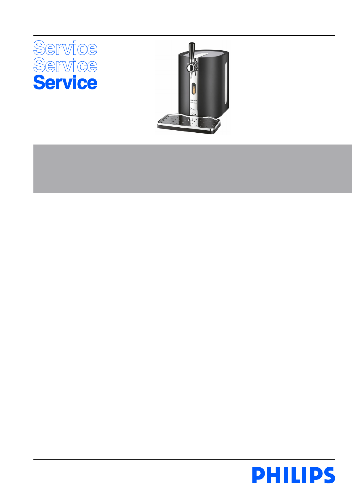
Perfect Draft “Beer Tap”
HD3600/20
/B
Philips Domestic Appliances and Personal Care
Service Manual
PRODUCT INFORMATION
- This product meets the requirements regarding
interference suppression on radio and TV.
- After the product has been repaired, it should function
properly and has to meet the safety requirements as
officially laid down at this moment.
TECHNICAL INFORMATION
- Power : 70 W
- Power consumption :
- Cool down period average
(KEG 23 °C -> 3 °C) : 0.068 kWh
- Standby period
(KEG on 3 °C) : 0.052 kWh
- Voltage : 100 - 120 V - 50/60 Hz
200 - 240 V - 50/60 Hz
- Flow rate : 2 L per minute
- Contents Keg : 6 L
- Colour setting : Black/Metal
- SAP coding : HD3600/20/B
OPTIONAL (accessories)
- No specific issues
Published by Philips Domestic Appliances and Personal Care Printed in the Netherlands © Copyright reserved Subject to modification
07/06
Page 2

DISASSEMBLY- AND RE-ASSEMBLY ADVISE
HD3600/20/B
For your safety first be sure the plug is
disconnected from the mains!
Rear case removal:
- To remove the rear case, first remove the 4 screws.
- Open both doors, at the upper/lower right and left side the
screws can be found.
Replacing the Display: *
- When the display has to be replaced for some reason, the
complete Left door including display and flat cable has to
be replaced.
- Remove the rear case assy, see rear case removal for details.
- Disconnect the flat cable connector from the main PCB
that is coming from the left door.
- To re-assembly carry out steps backwards.
* Please note that from WK527 onwards there exists
two different type versions of Display/door assy, if
those versions will be mixed up the appliance will
not work properly!
(See page 14 for the explanation/description!)
Replacing the Fan assy:
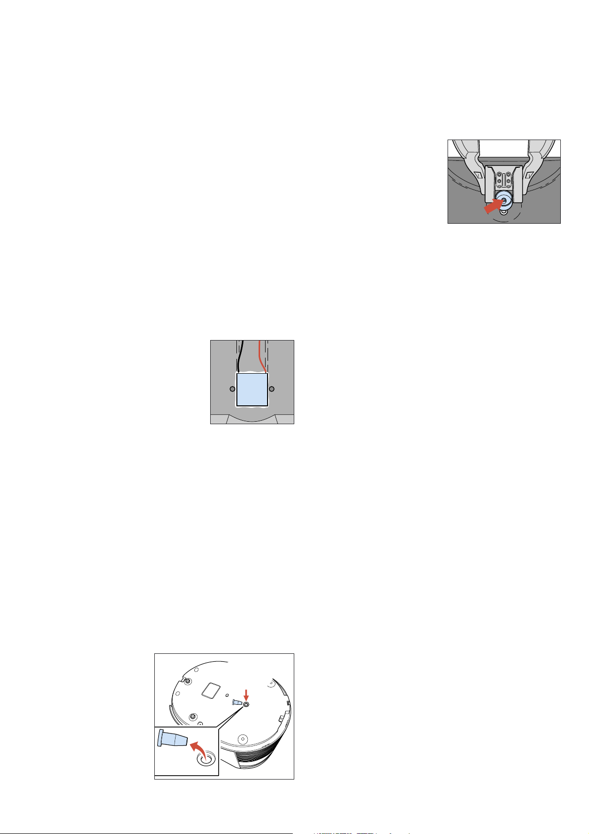
- When the Fan has to be
replaced, unscrew the 4 posi
screws and disconnect the
connector of the Fan.
- When re-assemble the fan
assy, be sure that the airflow
(see arrow on the Fan) is
appointing to the heatsink.
NOTE:
When the Fan became defect also Peltier
element has to be replaced or fully checked on
performance. Due to overheating also the Peltier
element will be damaged.
Picture 3.
Picture 1.
- When the rear has been removed all parts can easy be
reached.
Replacing the Keg Connector Assembly:
- The Keg connector assembly is very accurate outlined with
assembly at production.
- This has been done to be sure all Kegs will fit easily without
leakage to the machine.
- To be sure to place the new Keg connector assembly on
the same spot, make the following precautions before
unscrewing the Keg connector assembly.
- With a sharp screwdriver,
scriber or marking tool you
have to make a mark on the
plastic, see picture for detail.
- When the mark has been
carried out, you can unscrew
the 4 posi screws and remove
the Keg connector assembly.
Picture 2.
- When reassemble the new Keg connector assembly, first
connect the air pressure hose and then make sure that the
new part will be outlined next to the marking you just
made with the original part.
2-15
Page 3
DISASSEMBLY- AND RE-ASSEMBLY ADVISE
Replacing the Peltier element:
- When the Peltier element has to be replaced, first remove
the rear case assy and Fan assy.
- Unscrew the 2 screws located on the heat sink.
- The heat sink including Peltier element can now be
removed.
- With a small screwdriver the Peltier element can be removed
from the heat sink, some force maybe needed.
- Before placing the new Peltier element, provide heat sink
paste on both side of the Peltier element.
- Place the new Peltier element on the cooler plate on the
same position of the removed Peltier element.
NOTE! It is important to place the Peltier element with
the right side on the COOLER PLATE.
- The cooler plate is the aluminium part fixed in the
appliance, where the KEG will be cooled on.
- The heat sink is the aluminium part where the fan is
assembled on.
- In other words, the cooling side of the Peltier has to point
to the COOLER PLATE and the warm side has to point to
the HEAT SINK.
- Details to check are:
• Soldered joints must be pointing
to the cooling plate.
(when Peltier is placed on the
cooler plate the soldered joints
are not visible, seen from the
backside)
• Colours of wires must be equal
positioned see, picture for detail.
- Be careful and make sure the Peltier element is well placed.
- Now the heat sink can be placed on the peltier element.
- Tighten the screws alternate, to prevent damaging the
Peltier element for mounting lop-sided.
- Maximum force that maybe applied to tighten the screws
are: 0.6 Nm.
Procedure for checking cool down
performance Peltier element.
To ensure the Cool performance of the Peltier element is
according specifi cation the below test procedure have to be
carried out.
- Preparations:
1. Switch the appliance off and let it stabilize until it
reached room temperature.
2. Remove under the base in the middle the rubber Cap.
3. The chiller plate
becomes visible.
Picture 4.
contact
temperature
probe
HD3600/20/B
- Performing the temperature measurement, when the unit
has reached the room/environment temperature.
1. Place a contact temperature probe against the chiller
plate where the rubber cap was removed.
2. Block the air inlet
coupling at the Keg
side, see picture 6 for
location.
Picture 6.
3. Plug the appliance in the wall socket and bridge over
the Keg present switch mechanically or electrically so
the appliance will start.
4. When the appliance has started the pump will run
shortly (in case the air inlet has been blocked properly)
5. Readout the temperature meter and note it down.
6. Keep the appliance switched on for 2 minutes, readout
the temperature again.
7. If the temperature has decreased more then 6 °C,
between the two measurements the cooling works fine,
if not please check again or replace Peltier or Fan assy.
- Final:
When the appliance is checked and OK, place the rubber
Cap back under the base.
Replacing pressure sensor PCB:
- To replace the pressure sensor PCB assy, situated on the
pump, unscrew the 2 screws completely.
- Disconnect the connector, gently turn the PCB assy left and
right and at the same time pull the unit up.
Sometimes also the side cap must be unscrewed a little to be
able to remove the pressure sensor.
- Place the new PCB assy and check if the small rubber ring
on the sensor tube is on its place.
Replacing the pump unit:
- Start with disconnecting the air pressure hose and electrical
connections.
- Unscrew the 3 screws from the plastic bracket were the
pump unit is hanging on.
- To re-assembly carry out steps backwards.
NOTE! To prevent leakage at the connection side of the
hose, cut a small piece off the end of the hose.
rubber
Cap
Picture 5.
3-15
Page 4
REPAIR INSTRUCTIONS
Electrical circuit:
- When the appliance does not work, check the electrical circuit.
HD3600/20/B
Beer outlet
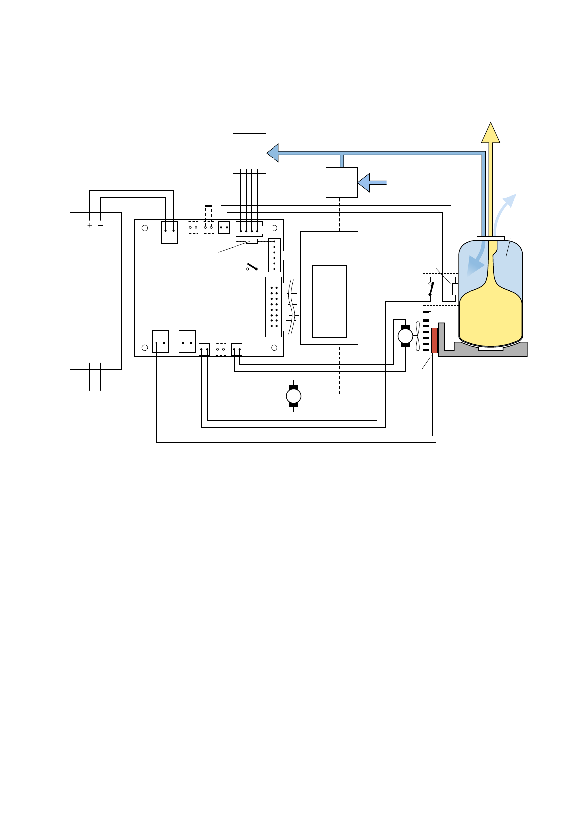
Process block diagram of the appliance
Shortcut to
enter Service
mode
10.5 V
Power supply
Mains
(120 V or 230 V)
J1
J4 J3
Interface board
(rear panel)
J8 J7 J11 J6 J5
J2
10k
pull-down
Step through
Service mode
Pressure
Sensor
PCB
J10
J12
J9
M
Air
pump
Micro controller
PCB
(Front panel)
Display
Air inlet
Keg present
switch
Heatsink
M
Fan
Peltier
NTC
Keg
Beer in
plastic bag
Chillerplate
Keg fill air
release
Compressed
air
Picture 7.
Working principle of the appliance
- To understand the appliance better hereby a short description of the working principle.
- Beer, the Beer is stored in a plastic bag inside the Keg, see picture 7.
- The Beer only comes in contact with the tube connector and never with the appliance.
- When the tap unit and tube connector are connected on the Keg and the Keg is placed in the appliance, the Keg present switch
will be activated.
- Once the appliance is activated after approximately 10 seconds you will hear a pump running.
- The task of this pump is to fill the space between the plastic bag and the walls of the Keg with air and create an overpressure
situation (Overpressure ± 1500 mBar).
- Through the over pressure around the plastic bag (comparable like you squeeze into the plastic bag) the Beer will be pressurized
(sort of) as well.
- By pulling the tap handle the tube connector hose will become opened and the Beer will flow out of the plastic bag via the tube
connector in to the glass.
- After this cycle the pump will start running to go back into the overpressure situation like described before.
- When the Keg present switch has been actuated also the cooling process (Peltier element) will be started and display functions will
become visible.
- The temperature will be measured by a NTC located in the Keg present plunger and indicated on the display.
- The volume indication measurement is based on the principle of a pressure drop measurement, measured by a pressure sensor.
- When pouring Beer, the pressure in the KEG will decrease, the amount that the pressure will decrease in a period of time will be
calculated through the system.
- The result of this calculation will be indicated on the display.
- The volume indication steps are dived in 4 steps of 25 %.*
* Note that from WK532 onwards the volume indication steps have been adapted from 4 levels to 8 levels.
(See page 14 for the explanation/description!)
4-15
Page 5
REPAIR INSTRUCTIONS
Service testroutines
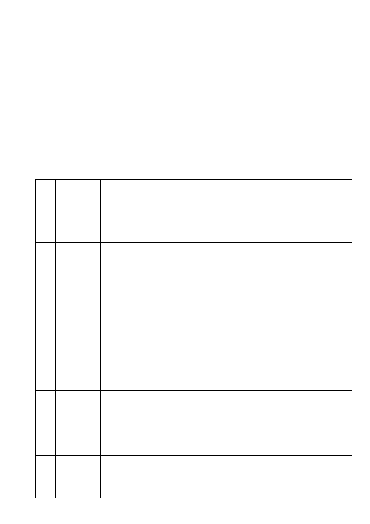
- This appliance has been equipped with special service routines to be able to check several functions of the appliance.
- Below the necessary steps will be described to enter into the service mode.
- Please follow the instructions carefully to avoid damaging the electronic circuit of the appliance.
Putting the appliance into Service mode.
1. Disconnect the appliance from mains.
2. Remove the keg.
3. Shortcut connector J3. (see picture 7)
4. Connect a simple push button to connector J9.
5. Connect the appliance to mains.
Stepping through the Service mode.
- As the Service Mode is entered, the display will show the software version, Service Mode 0.
- Every time the push button is activated, the next Service Mode is entered, forcing another part of the appliance to become active.
The list below shows all the possible Service Modes.
- After mode 10, the routine jumps back to mode 1.
Mode Test Stimulus Response Remark
No test Shows software version 2 digits. E.g. 20 = version 2.0
0
Display test 1. Display shows red 1
2. Display blanks
1
Pump motor 1. Pump motor starts running.
2
Fan motor
high level
3
Fan motor
low level
4
Peltier low 1. Peltier starts cooling.
5
Peltier medium 1. Peltier starts cooling.
6
Peltier high 1. Peltier starts cooling.
7
8
9
10
Pressure
measurement
Temperature
measurement
Keg Activation
switch
Connect dummy
pressure sensor
Connect dummy
NTC sensor
Operate the Keg
Activation switch
3. All segments on (red)
4. All segments on (green)
5. Repeat from 2.
2. Display shows red 2.
1. Fan starts running.
2. Display shows red 3.
1. Fan starts running.
2. Display shows red 4.
2. Display shows red 5.
2. Display shows red 6.
2. Display shows red 7.
1. Display shows full bar, graph if ok.
2. Display shows red 8.
1. Display shows full bar, graph if ok.
2. Display shows red 9.
1. Bar graphs off (not activated)
or on (activated).
2. Display shows red 10.
Segment test runs automatically
Pump runs; Voltage across pump:
~9 Vdc / ~2.7 Vrms
Fan runs on high level (100%)
Voltage across fan:
~10.5 Vdc / ~0 Vrms
Fan runs on low level (~75%)
Voltage across fan:
~8.9 Vdc / ~0.25 Vrms
Peltier runs on low level (~10%)
Voltage across Peltier:
~2.3 Vdc / ~3.0 Vrms
Current through Peltier: ~2.3 Arms
(Fan keeps running at high level)
Peltier runs on medium level (~50%)
Voltage across Peltier:
~6.0 Vdc / ~4.0 Vrms
Current through Peltier: ~4 Arms
(Fan keeps running at high level)
Peltier runs on high level (100%)
Voltage across Peltier:
~10.5 Vdc / ~0.0 Vrms
Current through Peltier:
>4.7 Arms (lower = defect Peltier
(Fan keeps running at high level)
Replace pressure sensor by dummy
sensor
Replace NTC sensor by dummy
sensor
HD3600/20/B
5-15
Page 6
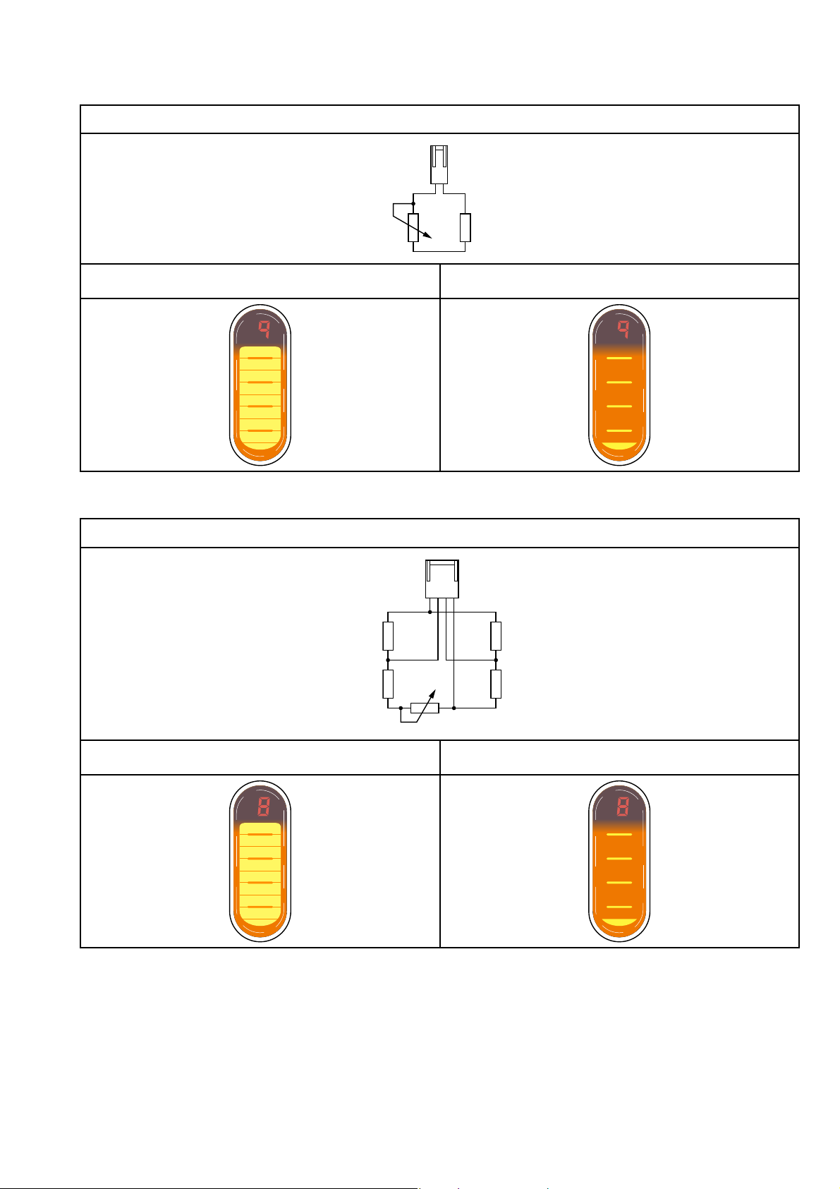
k
REPAIR INSTRUCTIONS
HD3600/20/B
NTC DUMMY:
J2
5k
19
NTC value 20 kΩ < Rdummy < 22 kΩ (= 4 °C ... 6 °C) Any other value:
PRESSURE SENSOR DUMMY:
1
J12
4k7
4k7
4k7
1k
4k7
Input voltage 9 mV < Vdummy < 10 mV (900 ... 1100 mbar) Any other value:
6-15
Page 7
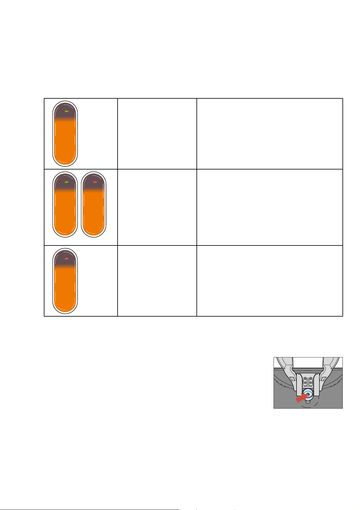
REPAIR INSTRUCTIONS
Trouble shooting:
1. Appliance doesn’t work at all
Check if the KEG PRESENT switch is functioning OK or check the Voltage output (10 V ± 0.5 V) of the Power supply.
2. Display Error signals
If somehow the system detects a problem, in a few occasions the system is able to use the display for displaying the type of error
detected by the system.
HD3600/20/B
DISPLAY no tap unit
Static segment green
Background lights on
Bar graphs off
DISPLAY leakage
Static segment green or red.
Blinking background
Bar graphs off
DISPLAY no keg
Static segment red
Background lights on
Bar graphs off
Way of software detection:
When the system detects no pressure rise during running of
the pump (duration measurement 10 seconds), the software
will interpret that there is no tap unit on its place.
Checks:
• Is the pressure sensor function correctly?
(See chapter repair instructions, service test routines to
check with dummy)
• Is a huge air leakage noticeable in the system?
Way of software detection:
When the system detects a pressure fall which is greater
than normal occur when pouring Beer, the software will
interpret that there is a leakage in the system.
Measurement take approximately 300 seconds.
Checks:
• Is the pressure sensor function correctly?
(See chapter repair instructions, service test routines to
check with dummy)
• Is a huge air leakage noticeable in the system?
Way of software detection:
The KEG present/activation switch will give input to the
Interface board.
Checks:
• Is the micro switch function correctly?
(See chapter repair instructions, service test routines to
check the switch in combination with interface board)
3. Blinking display or pump is “to” often activated. (Air Leakage)
If the display is blinking or the complaint is that the pump is running very often (more than 4 times per hour without pouring
Beer), the cause could be that there is air leakage in the air pressure system.
Possible components to check are Keg, tube connector, tap unit, pump, hose or pressure sensor.
Checking the problem to determine if the leakage is located inside the appliance or outside.
Step 1: Remove the Keg and tap unit.
Step 2: Block the air Inlet coupling at the Keg side.
See picture 8 for location, be sure the hole is blocked.
Step 3: Actuate the KEG present switch (for example putting a Keg without tap unit in the
appliance) after ± 10 seconds the pump will start running)
When the pump has stopped, wait ± 300 seconds after this time has passed, check if the display
reading is normal (not blinking) also the pump may not run in this period of 300 seconds.
When the system has detected a air leakage by itself, the backlight of the display starts blinking.
(see also point 2, Display error signals for details)
When the system is function correctly and there is absolutely no air leakage the pump runs two or three times per 24 Hours.
Possible root causes that have to be checked are, tube connector, Keg, tap unit and connections.
If the pump keeps pumping or the system is displaying a leakage error, other internal root causes to be checked are, leakage at
connections of hose and components, pressure sensor leaks or is electronically defect see chapter repair instructions, service test
routines step 8 to check the electronic parts.
Leakage problems can be found by providing a little bit water and soap on the suspected places to see if the air bells are visible
when the pump is activated.
When internal no failures are found please check the external parts like KEG, tap unit and tube connector.
Picture 8.
7-15
Page 8

REPAIR INSTRUCTIONS
4. Cooling problems.
Several causes can influence the unit from cooling down.
Cool down process takes very long. (more than 18 hours KEG 23 °C -> 3° C)
- Check the usage conditions; the cooling principle of the appliance is based on a Peltier element. The Peltier element works by
withdrawn heat that results in the fact that the surface on the other side of the element will cool down. To be sure the Peltier
element is doing it’s job well it is very important that the airflow from the fan that transports the produced warmth out of the
appliance is free (± 10 cm) space around the appliance.
- Check if the ambient temperature did not exceed 25 °C.
- Check if the fan is turning well and there is no blockage caused by dust or other particles.
- Check if the Fan is correct placed (see chapter DISASSEMBLY- AND RE-ASSEMBLY ADVISE, replacing the Fan assy for
details).
Unit doesn’t cool down.
Probable root causes:
- Peltier element became defective.
(see chapter repair instructions, service test routines steps 5 - 7 to check the electronic parts)
- Temperature Sensor is filthy or defective were through the cooling control process is derangement.
(see chapter repair instructions, service test routines step 9 to check the electronic parts)
- Display temperature reading is not reliable. (To check the display reading, place a temperature sensor next to the location of
the KEG present plunger, after ± 5 minutes of stabilization check the temperature reading from the display with the external
temperature measurement device.
Because the temperature sensor is placed in the middle of the KEG, subtract a 4.2 °C from the external placed temperature
meter before judging the values.
After subtraction of 4.2 °C, deviation aloud +/− 1° C, below 3° C −1 °C / +2 °C)
Example:
External indication temperature meter 7.2 °C
Display reading PerfectDraft system 3 °C
Conclusion (7.2 reading ext. − 4.2 offset value) = 3 °C, appliance within spec.
5. Beer leakage.
If the consumer complains about Beer leakage, most probably items that have to be checked are Keg, tube connector and
tap unit.
If the Beer leakage is noticed at the spout side, please check the tube connector on presence of hair-line cracks or check if the
tube connector is good positioned.
Other possibility could be that the closing mechanism of the tap unit does not block the Beer tube accurate.
If the Beer leaks more at the Keg or tap unit position, please check the Keg, tube connector or tap unit on visual aspects.
6. Condensation water leakage.
When the consumer complains about Beer/water under the appliance most probably cause is that either the drip tray unit was
not good placed under/against the appliance or the drip tray was not emptied on time, which can cause overflow of a mix of
Beer and water.
Other possibility could be that the doors were not closed properly.
7. Temperature display reading cannot be trust.
If the Display reading is not trustful or values are displayed that are not in line with what maybe expected, the display reading
has to be checked.
For checking the temperature reading please see under Trouble shooting point 4 Cooling problems or to determine if the
temperature sensor or circuit board has become defect, please see chapter repair instructions, service test routines step 9 to
check the electronic parts.
It is not possible to adjust the temperature measuring system of the appliance.
HD3600/20/B
8-15
Page 9
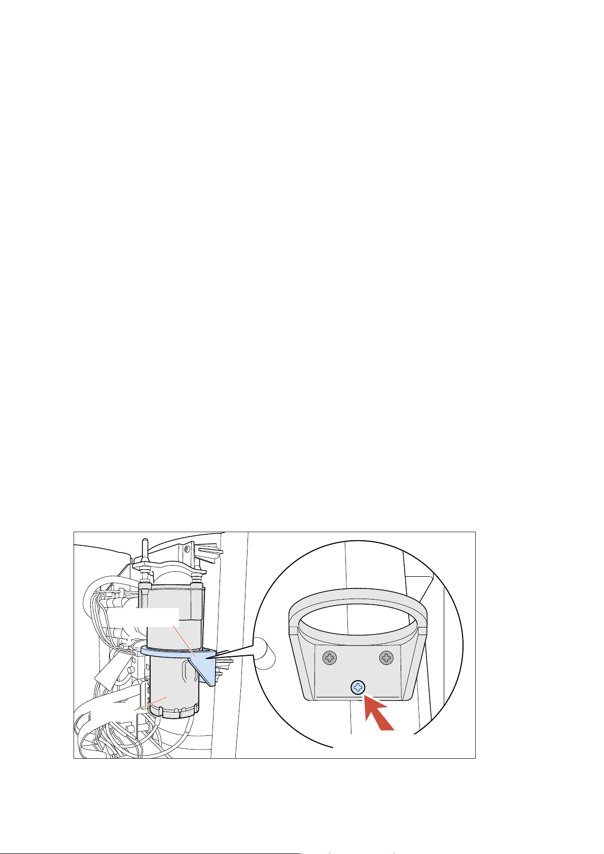
REPAIR INSTRUCTIONS
8. Beer volume indication.
The Beer volume indicator is a device to give the consumer an impression about the amount of Beer left in the KEG.
This indicator is not accurate only steps of 25 % are possible to display.
From WK532 onwards the software has been upgraded to version 6.4.
The volume indication levels are improved from 4 to 8 levels.
This results in more accurate volume indication.
For revision changes (See page 14 for the explanation/description!)
When the consumer is complaining about the fact that the display indicates a empty KEG but there is still Beer left in the KEG
this is actually not a failure in the appliance.
When less then 30 % of the volume is measured by the system the display will indicate 0 %.
(OLD version before WK532, see revision changes page 14 for the explanation/description)
Other complaints of the consumer could be that the display shows 100 % volume, but there is already Beer out of the KEG.
If for some reason the appliance has been switched off or a voltage dip has occurred in the mains network or the KEG has been
removed and replaced again, the system will start with a 100 % volume indication.
After pouring one or two glasses of Beer, the volume indication will be recalculated and displayed.
If the volume indication is for some reason not thrust full, the cause could be that there is an air leakage in the system.
In that case most likely parts to check are Beer tube connector, KEG or Adaptor. See under Trouble shooting point 3 Blinking
display or pump is “to” often activated. (Air Leakage).
9. No foam on the Beer.
If the complaint is that there is “almost” or no foam on the Beer, the following have to be checked.
1) Temperature of the Beer must be below 9° C, check DFU for more tips.
2) Glasses have to be clean, check DFU for more tips!
3) Beer tube connector is not properly installed or is damaged, check DFU for more tips.
10. To much foam.
If the complaint is that there is to much foam on the Beer, the following have to be checked.
1) Temperature of the Beer must be below 9 °C, check DFU for more tips.
2) The Beer tube is not properly installed or is damaged, try new Beer tube.
3) There must be no air leakage in the system.
11. Avoiding ticking noise/signal of starting pump.
If consumers are complaining about a ticking noise when the pumps start running the following can be done to solve the
problem.
The problem is caused by the fact that when the pumps start running it hits a screw of the drop ring fixation of the pump.
See location for the drop ring in below picture.
HD3600/20/B
Drop ring
Pump
Picture 9
The problem can be solved by removing the screw, see picture above.
Removing the screw does not harm or affect the strength of the construction.
Screw to remove
9-15
Page 10
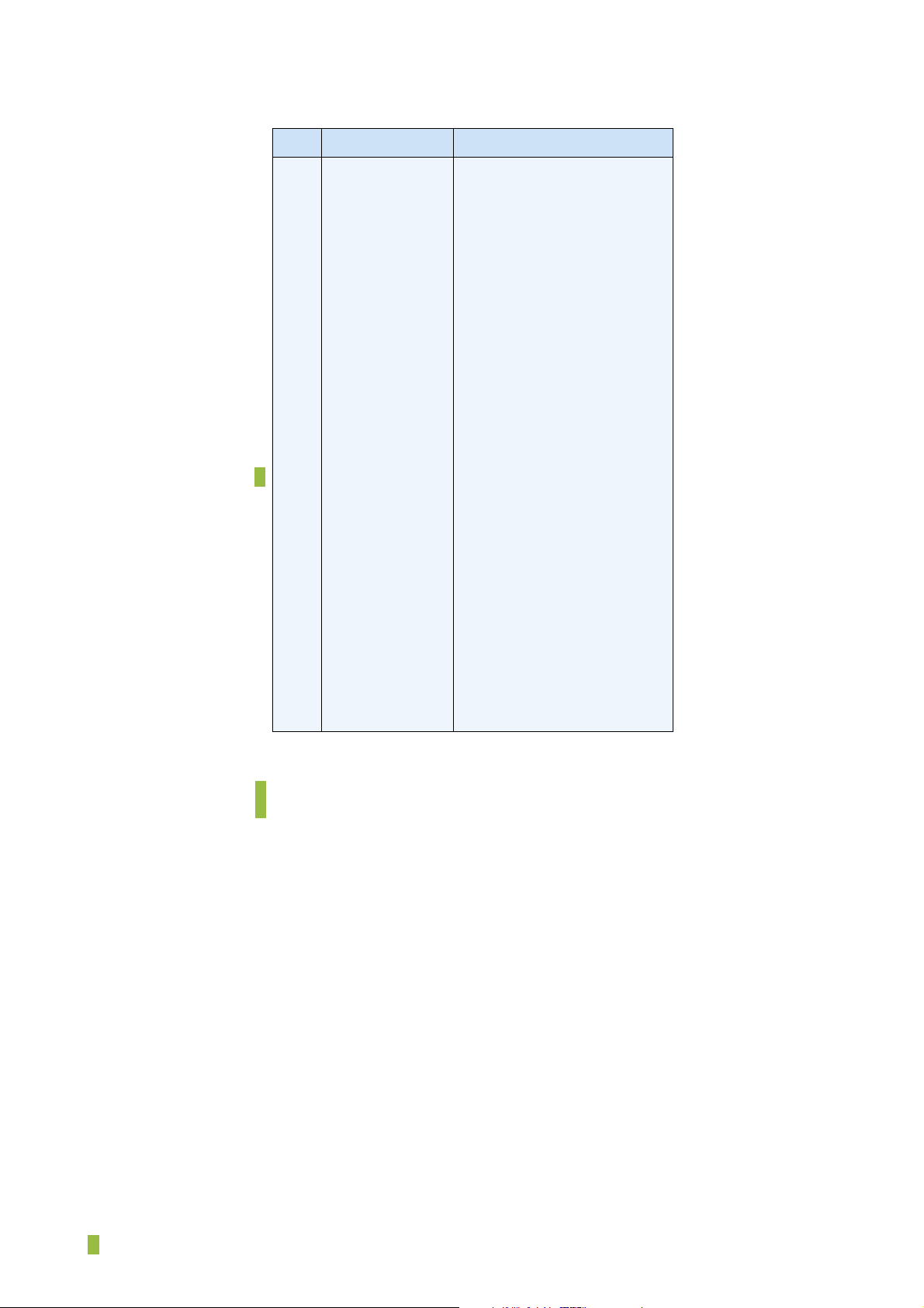
PARTS LIST
HD3600/20/B
Pos Service code Description
1
2 *
3
4
5
6
7
8
9
10
11
12
13
14
15
**
17
18
19
20
21
22
23 *
24
25
26
27
28
9965 000 26106
9965 000 26113
9965 000 26114
9965 000 26107
9965 000 26108
9965 000 26121
9965 000 26122
9965 000 26124
9965 000 26123
9965 000 32659
9965 000 26126
9965 000 26125
9965 000 26129
9965 000 26130
9965 000 26127
4222 459 45067
9965 000 26115
9965 000 26116
9965 000 26131
9965 000 26117
9965 000 26118
9965 000 26120
9965 000 26112
9965 000 26119
9965 000 26111
9965 000 26110
9965 000 26109
9965 000 32874
Rear case assy
Left Door/display assy
Right Door assy
Steelplate driptray
Baseplate Driptray
Handle assy
Handle O-ring
Spout O-ring
Spout
O-ring
O-ring 11X2 Air inlet side
Tap unit
Connector/Lever assy
Air coupling
Sensor assy
Special sensor assy
Grommet. Pump position
Pump assy
Seal
Pressure sensor PCB assy
Pressure hose assy
Power supply HV 220-240V
Main PCB
Peltier assy
Micro switch assy
Grommet, FAN position
Fan assy
Drop ring
* New versions are delivered from stock september 2005 onwards.
See page 14 for the explanation/description!
** Remark to be used for appliance produced after WK539 and with cooling complaints
Beer too cold or display indication becomes not lower then 5 - 7 °C.
= changed
10-15
Page 11
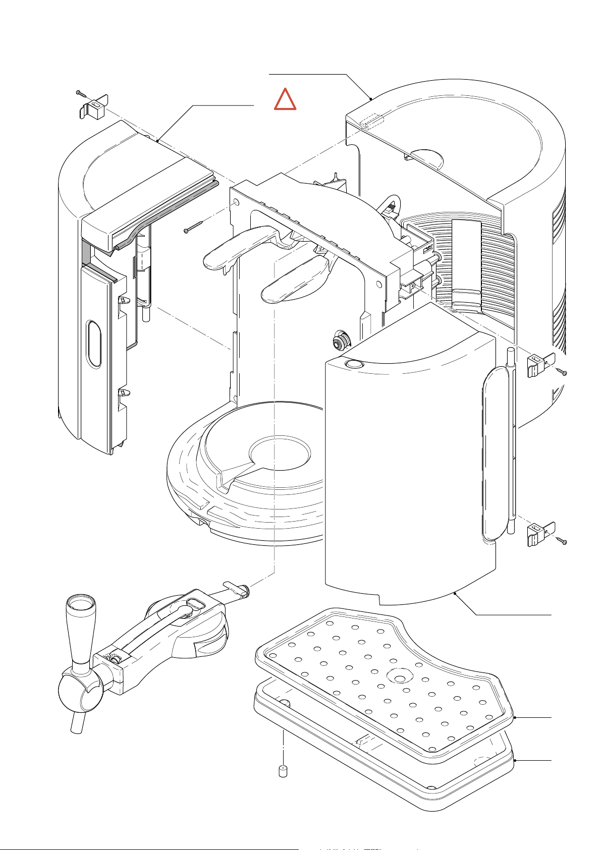
EXPLODED VIEW
1
*
2
See
page 14
HD3600/20/B
!
3
4
5
11-15
Page 12
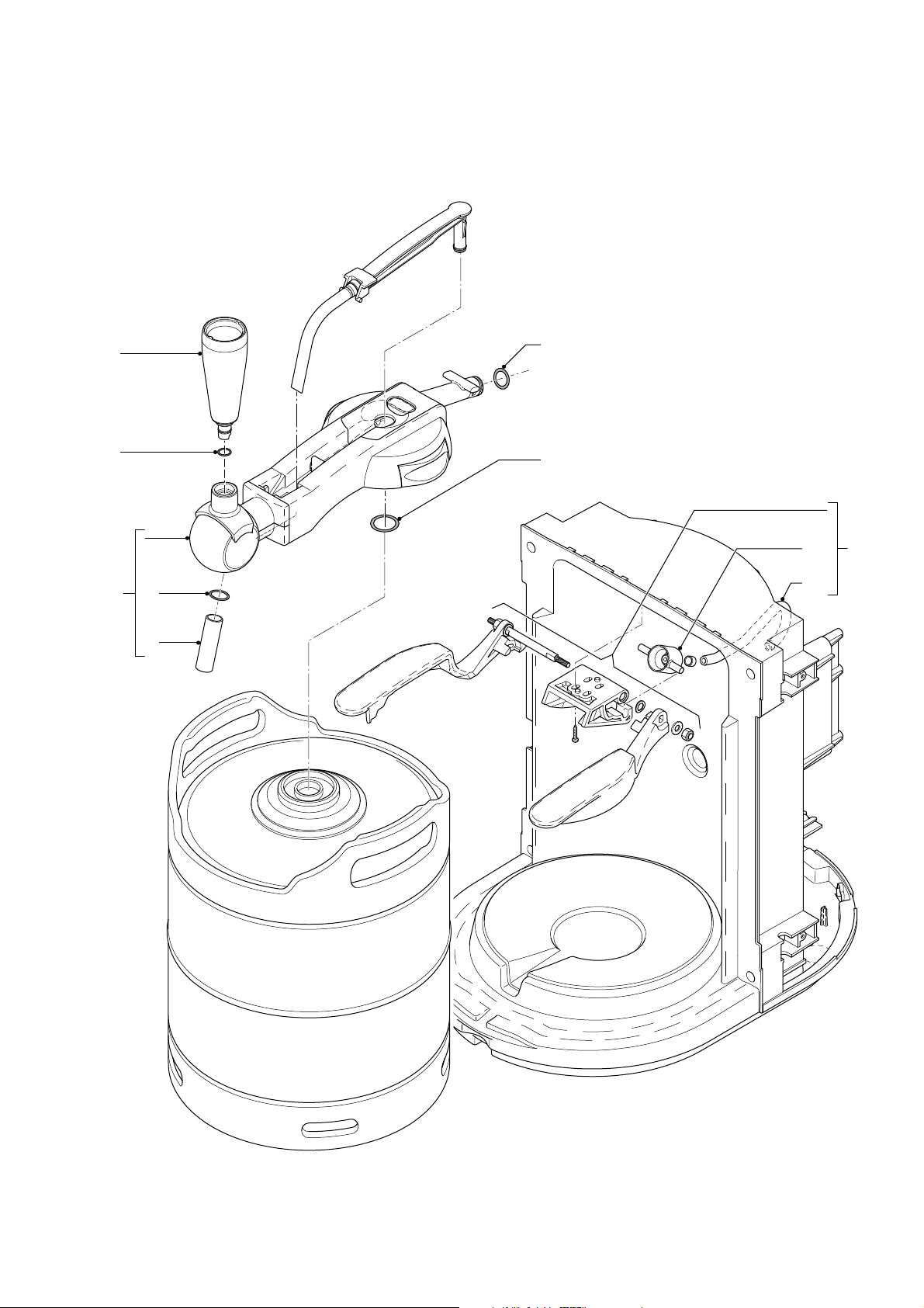
EXPLODED VIEW
HD3600/20/B
12
6
7
8
9
11
10
14
21
13
12-15
Page 13
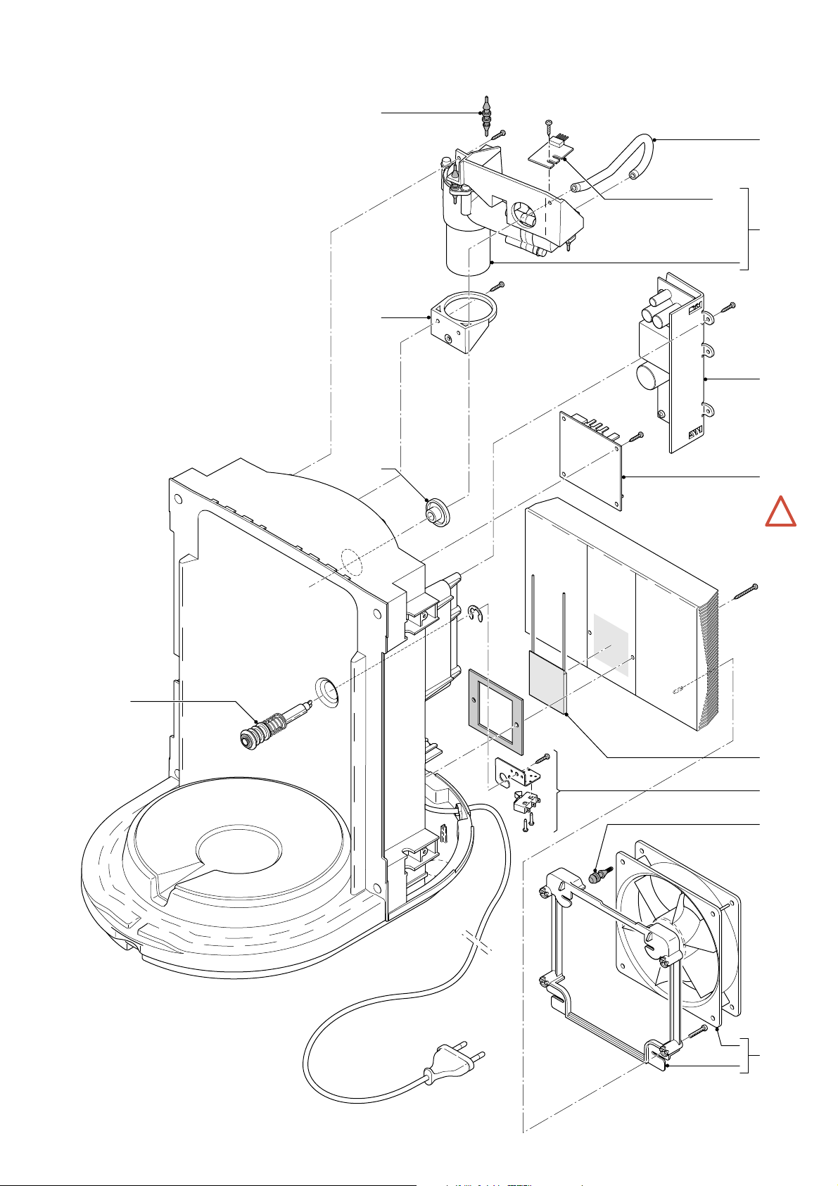
EXPLODED VIEW
HD3600/20/B
17
21
20
18
28
22
15
19
See
page 14
23
24
25
26
*
!
27
13-15
Page 14
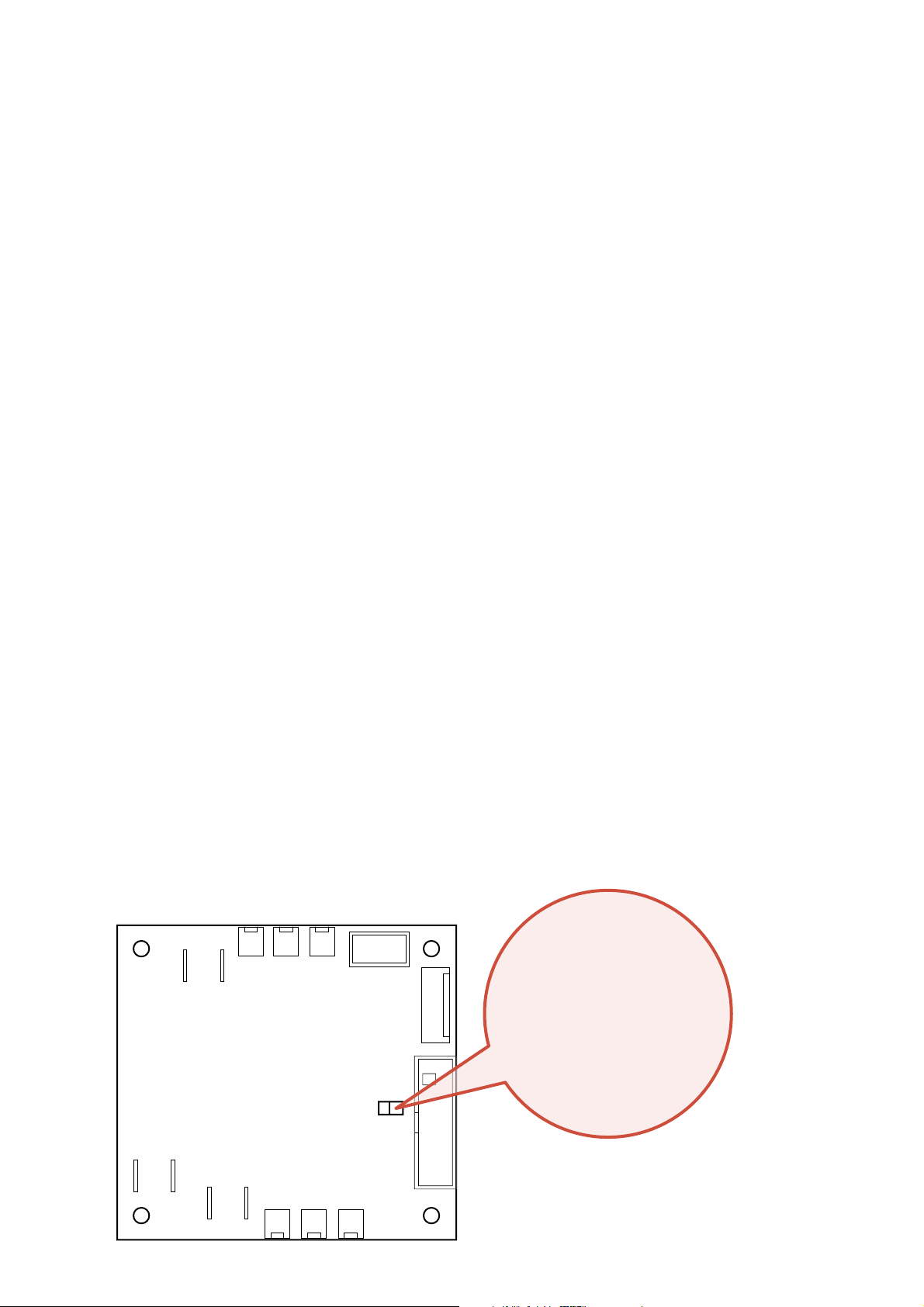
REVISION HARD & SOFTWARE CHANGES.
HD3600/20/B
From wk527 onwards the hardware components like the interface board/main PCB (item 23 in the exploded view) and the
processor/controller board (build in the left door item 2 in the exploded view) have changed in the PerfectDraft appliance.
Important Hardware changes.
The two different interface and processor/controller boards are not fully interchangeable.
The fi rst impression when components are used through each other will be that the appliance is working fi ne.
But the fact is that the temperature control will not work right.
Using the mix of components will end up in a appliance which temperature reading is not trustworthy and even can result in
lukewarm Beer.
Important software changes.
WK527 the software (ver: 4.6 to ver: 6.3) for operating with the new processor/controller board the software has been upgraded.
(from the outside no apparently change noticeable)
WK532 the software version has been upgraded to ver: 6.4.
With this upgrade the Beer volume indication steps on the display have changed from 4 into 8 levels.
Through this improvement the Beer level indication becomes more accurate.
How do I recognize the different versions?
Processor/controller boards: (HARDWARE)
The processor/controller board is assembled in the left Door with display.
That means that from the outside it is not possible to see the differences between “old” and “new”.
To determine the difference:
1. By checking the stroke number on the type number plate. /A (“old” version) or /B (“new” version) of the appliance.
2. Check if Jumper J13 is present or pads J13 position have been soldered through on the interface board / Main PCB item 23.
(if not present or pads are soldered through, the “old” processor/controller has been applied)
3. By reading out the Firmware version number, see chapter REPAIR INSTRUCTIONS, service test routines page 5-12.
See matrix how to use the different versions.
Interface board / Main PCB (Item 23)
There are 3 possibilities for checking the interface / Main PCB version:
1. By checking the stroke number on the type number plate. /A (“old” version) or /B (“new” version) of the appliance.
2. Check the Revision number that is printed on the board.
3. Check if Jumper J13 is present or pads have been soldered through on the interface board.
(if so, by checking the status of jumper position J13, it is also possible to determine which processor/controller board has
been applied.
See matrix how to use the different versions.
Supply
INTERFACE Rev 3.5
J2J3J4
J12
J9
Jumper J13.
Closed for “Old” controller.
(produced before WK527)
Open for “NEW” controller.
(produced onwards WK527)
J13
J10
Peltier
Pump
J11 J6 J5
14-15
Page 15
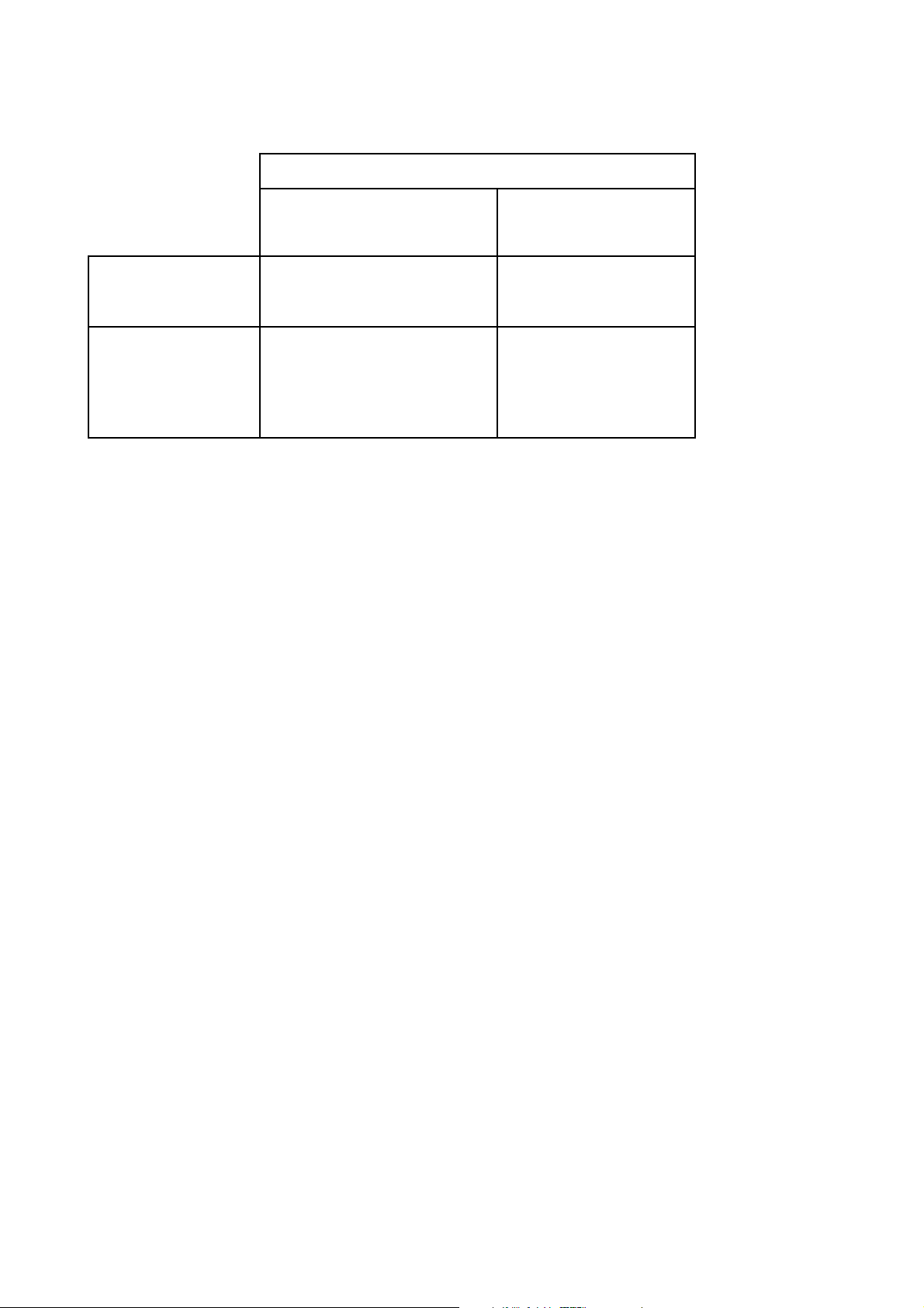
REVISION HARD & SOFTWARE CHANGES.
Matrix how to use several configurations.
HD3600/20/B
Processor used
“Old hardware”
Type plate /A
Firmware ver. 4.X
Interface board Rev 3.3 X
X
Interface board
Rev 3.4 & 3.5
Example 1:
Appliance stroke version /A, interface board ver 3.3 is defect.
Solution: order preferable new interface board ver 3.4 & 3.5,
solder pads through or place a jumper on J13
(J13 closed).
(use jumper or solder pads through)
J13 closed
see picture for location
“NEW hardware”
Type plate /B
Firmware ver. 6.X
X
J13 open
(no jumper or soldered)
see picture for location
Example 2:
Appliance stroke version /A, processor/controller is defect
original parts are no longer available.
Solution: order new version Door/Display assy and new
interface board ver 3.5, leave J13 (open).
15-15
 Loading...